EP2319604B2 - Wabenfilter - Google Patents
Wabenfilter Download PDFInfo
- Publication number
- EP2319604B2 EP2319604B2 EP10156879.8A EP10156879A EP2319604B2 EP 2319604 B2 EP2319604 B2 EP 2319604B2 EP 10156879 A EP10156879 A EP 10156879A EP 2319604 B2 EP2319604 B2 EP 2319604B2
- Authority
- EP
- European Patent Office
- Prior art keywords
- honeycomb
- zeolite
- structured body
- cell wall
- honeycomb filter
- Prior art date
- Legal status (The legal status is an assumption and is not a legal conclusion. Google has not performed a legal analysis and makes no representation as to the accuracy of the status listed.)
- Active
Links
Images

Classifications
-
- B—PERFORMING OPERATIONS; TRANSPORTING
- B01—PHYSICAL OR CHEMICAL PROCESSES OR APPARATUS IN GENERAL
- B01D—SEPARATION
- B01D46/00—Filters or filtering processes specially modified for separating dispersed particles from gases or vapours
- B01D46/24—Particle separators, e.g. dust precipitators, using rigid hollow filter bodies
- B01D46/2403—Particle separators, e.g. dust precipitators, using rigid hollow filter bodies characterised by the physical shape or structure of the filtering element
- B01D46/2418—Honeycomb filters
- B01D46/2425—Honeycomb filters characterized by parameters related to the physical properties of the honeycomb structure material
- B01D46/2429—Honeycomb filters characterized by parameters related to the physical properties of the honeycomb structure material of the honeycomb walls or cells
-
- B—PERFORMING OPERATIONS; TRANSPORTING
- B01—PHYSICAL OR CHEMICAL PROCESSES OR APPARATUS IN GENERAL
- B01D—SEPARATION
- B01D46/00—Filters or filtering processes specially modified for separating dispersed particles from gases or vapours
- B01D46/24—Particle separators, e.g. dust precipitators, using rigid hollow filter bodies
- B01D46/2403—Particle separators, e.g. dust precipitators, using rigid hollow filter bodies characterised by the physical shape or structure of the filtering element
- B01D46/2418—Honeycomb filters
- B01D46/2425—Honeycomb filters characterized by parameters related to the physical properties of the honeycomb structure material
- B01D46/24491—Porosity
-
- B—PERFORMING OPERATIONS; TRANSPORTING
- B01—PHYSICAL OR CHEMICAL PROCESSES OR APPARATUS IN GENERAL
- B01D—SEPARATION
- B01D46/00—Filters or filtering processes specially modified for separating dispersed particles from gases or vapours
- B01D46/24—Particle separators, e.g. dust precipitators, using rigid hollow filter bodies
- B01D46/2403—Particle separators, e.g. dust precipitators, using rigid hollow filter bodies characterised by the physical shape or structure of the filtering element
- B01D46/2418—Honeycomb filters
- B01D46/2425—Honeycomb filters characterized by parameters related to the physical properties of the honeycomb structure material
- B01D46/24494—Thermal expansion coefficient, heat capacity or thermal conductivity
-
- B—PERFORMING OPERATIONS; TRANSPORTING
- B01—PHYSICAL OR CHEMICAL PROCESSES OR APPARATUS IN GENERAL
- B01D—SEPARATION
- B01D46/00—Filters or filtering processes specially modified for separating dispersed particles from gases or vapours
- B01D46/24—Particle separators, e.g. dust precipitators, using rigid hollow filter bodies
- B01D46/2403—Particle separators, e.g. dust precipitators, using rigid hollow filter bodies characterised by the physical shape or structure of the filtering element
- B01D46/2418—Honeycomb filters
- B01D46/2451—Honeycomb filters characterized by the geometrical structure, shape, pattern or configuration or parameters related to the geometry of the structure
- B01D46/247—Honeycomb filters characterized by the geometrical structure, shape, pattern or configuration or parameters related to the geometry of the structure of the cells
-
- B—PERFORMING OPERATIONS; TRANSPORTING
- B01—PHYSICAL OR CHEMICAL PROCESSES OR APPARATUS IN GENERAL
- B01D—SEPARATION
- B01D46/00—Filters or filtering processes specially modified for separating dispersed particles from gases or vapours
- B01D46/24—Particle separators, e.g. dust precipitators, using rigid hollow filter bodies
- B01D46/2403—Particle separators, e.g. dust precipitators, using rigid hollow filter bodies characterised by the physical shape or structure of the filtering element
- B01D46/2418—Honeycomb filters
- B01D46/2451—Honeycomb filters characterized by the geometrical structure, shape, pattern or configuration or parameters related to the geometry of the structure
- B01D46/2476—Monolithic structures
-
- B—PERFORMING OPERATIONS; TRANSPORTING
- B01—PHYSICAL OR CHEMICAL PROCESSES OR APPARATUS IN GENERAL
- B01D—SEPARATION
- B01D46/00—Filters or filtering processes specially modified for separating dispersed particles from gases or vapours
- B01D46/24—Particle separators, e.g. dust precipitators, using rigid hollow filter bodies
- B01D46/2403—Particle separators, e.g. dust precipitators, using rigid hollow filter bodies characterised by the physical shape or structure of the filtering element
- B01D46/2418—Honeycomb filters
- B01D46/2451—Honeycomb filters characterized by the geometrical structure, shape, pattern or configuration or parameters related to the geometry of the structure
- B01D46/2478—Structures comprising honeycomb segments
-
- B—PERFORMING OPERATIONS; TRANSPORTING
- B01—PHYSICAL OR CHEMICAL PROCESSES OR APPARATUS IN GENERAL
- B01D—SEPARATION
- B01D46/00—Filters or filtering processes specially modified for separating dispersed particles from gases or vapours
- B01D46/24—Particle separators, e.g. dust precipitators, using rigid hollow filter bodies
- B01D46/2403—Particle separators, e.g. dust precipitators, using rigid hollow filter bodies characterised by the physical shape or structure of the filtering element
- B01D46/2418—Honeycomb filters
- B01D46/2451—Honeycomb filters characterized by the geometrical structure, shape, pattern or configuration or parameters related to the geometry of the structure
- B01D46/2484—Cell density, area or aspect ratio
-
- B—PERFORMING OPERATIONS; TRANSPORTING
- B01—PHYSICAL OR CHEMICAL PROCESSES OR APPARATUS IN GENERAL
- B01D—SEPARATION
- B01D46/00—Filters or filtering processes specially modified for separating dispersed particles from gases or vapours
- B01D46/24—Particle separators, e.g. dust precipitators, using rigid hollow filter bodies
- B01D46/2403—Particle separators, e.g. dust precipitators, using rigid hollow filter bodies characterised by the physical shape or structure of the filtering element
- B01D46/2418—Honeycomb filters
- B01D46/2451—Honeycomb filters characterized by the geometrical structure, shape, pattern or configuration or parameters related to the geometry of the structure
- B01D46/2486—Honeycomb filters characterized by the geometrical structure, shape, pattern or configuration or parameters related to the geometry of the structure characterised by the shapes or configurations
- B01D46/249—Quadrangular e.g. square or diamond
-
- B—PERFORMING OPERATIONS; TRANSPORTING
- B01—PHYSICAL OR CHEMICAL PROCESSES OR APPARATUS IN GENERAL
- B01D—SEPARATION
- B01D46/00—Filters or filtering processes specially modified for separating dispersed particles from gases or vapours
- B01D46/24—Particle separators, e.g. dust precipitators, using rigid hollow filter bodies
- B01D46/2403—Particle separators, e.g. dust precipitators, using rigid hollow filter bodies characterised by the physical shape or structure of the filtering element
- B01D46/2418—Honeycomb filters
- B01D46/2451—Honeycomb filters characterized by the geometrical structure, shape, pattern or configuration or parameters related to the geometry of the structure
- B01D46/2486—Honeycomb filters characterized by the geometrical structure, shape, pattern or configuration or parameters related to the geometry of the structure characterised by the shapes or configurations
- B01D46/2494—Octagonal
Definitions
- the present invention relates to a honeycomb filter.
- Toxic gases such as NOx contained in exhaust gases discharged from internal combustion engines, for example, vehicles such as buses and tracks, construction machines, and the like, and particulate matter (hereinafter, also referred to simply as "PM") have raised problems as contaminants harmful to the environment and the human body.
- PM particulate matter
- a urea SCR (Selective Catalytic Reduction) device including, as a main component, a honeycomb structured body (hereinafter also referred to as catalyst carrier) in which a NOx conversion catalyst is supported for converting NOx in exhaust gases (for example, Patent Document 1) .
- the urea SCR device includes a catalyst carrier, a holding sealing material which is wound around the periphery of the catalyst carrier for supporting the catalyst carrier, and a casing for placing therein the catalyst carrier and the holding sealing material.
- the urea SCR device also includes a urea spray nozzle for spraying urea water disposed anterior to the region through which exhaust gases flow into the catalyst carrier (at an upstream side of exhaust gases).
- the catalyst carrier has a pillar shape and is made of a porous ceramic.
- the catalyst carrier has a large number of cells placed in parallel with one another each extending in a longitudinal direction from one end to the other end of the catalyst carrier with a cell wall interposed therebetween.
- the cell wall supports a zeolite as a NOx conversion catalyst. The ends of the cells are not sealed with a sealing material, and thus each cell is penetrating from one end to the other end of the catalyst carrier.
- urea water is sprayed to the catalyst carrier. This causes thermal decomposition of the urea contained in the urea water by the heat of the exhaust gases to generate ammonia.
- NOx in the exhaust gases is reduced to N 2 by the effect of the zeolite supported on the cell wall and the ammonia and thus converted.
- the exhaust gases in which NOx has been converted are discharged from the other end side of the catalyst carrier.
- the DPF has a pillar shape and is made of a porous ceramic. Also, in the DPF, a large number of cells are placed in parallel with one another each extending in a longitudinal direction from one end to the other end of the DPF with a cell wall interposed therebetween. Either one end of each cell is sealed with a sealing material.
- Patent Document 3 describes a filter for exhaust gas decontamination which comprises a porous ceramic support and a catalyst coat layer having an active component of catalyst on the surface of support.
- the porous ceramic support has a porosity of 40-80% and has a thermal conductivity of 3-60 W/mK or the support has a thermal conductivity of 0.3-3 W/mK and comprises a high refractive index substance or pigment.
- Patent Document 4 describes an emission treatment system and method for simultaneously remediating nitrogen oxides (NOx), particulate matter, and gaseous hydrocarbons present in diesel engine exhaust streams.
- the emission treatment system has an oxidation catalyst upstream of a soot filter coated with a material effective in the Selective Catalytic Reduction (SCR) of NOx by a reductant, e.g., ammonia.
- SCR Selective Catalytic Reduction
- Also provided is a method for disposing an SCR catalyst composition on a wall flow monolith that provides adequate catalyst loading, but does not result in unsuitable back pressures in the exhaust.
- the present inventors tried to sequentially carry out conversion of NOx and removal of PM using the aforementioned urea SCR device and a DPF. Specifically, the present inventors connected the urea SCR device and the DPF in series and investigated various combinations of the urea SCR device and the DPF. As a result, the present inventors have found that it is possible to efficiently carry out conversion of NOx and removal of PM when the DPF is disposed at an upstream of exhaust gases closer to an exhaust outlet of a diesel engine so as to first remove PM, and then exhaust gases containing NOx are converted by a urea SCR device disposed at a downstream of the DPF.
- the present inventors have investigated and had an idea that integration of the function of the catalyst carrier of a urea SCR device and the function of a DPF would solve the space reduction problem. Accordingly, they have produced a honeycomb filter in which a zeolite is supported on a DPF.
- the present inventors investigated the causes of the reduction of the NOx conversion rate after regeneration process in the honeycomb filter in which a zeolite is supported on the cell wall.
- the honeycomb filter is heated to 850°C or more with the heat generated by burning of PM (hereinafter simply referred to as PM burning heat) in regeneration process.
- PM burning heat the heat generated by burning of PM
- the zeolite sinters when the honeycomb filter is exposed to a high temperature of 850°C or more for a long time (hereinafter, the temperature causing sintering of zeolite is also referred to simply as sintering temperature). This is supposed to be the cause for reduction of the NOx conversion rate after regeneration process.
- the present inventors made a keen investigation in view of prevention of sintering of zeolite and reached the idea that, if heat dissipation capability of the honeycomb filter is increased, PM burning heat generated in regeneration process can be efficiently dissipated, and therefore it is possible to prevent the honeycomb filter from being exposed to the sintering temperature for a long period of time.
- a honeycomb filter can have a high heat dissipation capability when the honeycomb filter has a predetermined thermal conductivity or more.
- the present inventors also have found that the NOx conversion rate of the honeycomb filter can be increased by controlling the porosity of the honeycomb structured body and the amount of the zeolite supported on the cell wall. Accordingly, the present inventors finally completed the present invention capable of solving the problems mentioned earlier.
- the honeycomb filter according to Claim 1 includes a honeycomb structured body having a large number of cells each sealed at either end thereof and placed longitudinally in parallel with one another with a cell wall therebetween and a zeolite supported on the cell wall of the honeycomb structured body, wherein the honeycomb structured body contains silicon carbide, a porosity of the cell wall of the honeycomb structured body is 55 to 65%, an amount of the zeolite supported on the cell wall is 80 to 150 g/L, and a thermal conductivity of the cell wall supporting the zeolite is 5 to 10 W/mK.
- the honeycomb filter according to Claim 1 can exert a high PM capturing effect and also can have a high NOx conversion rate even after repeating the regeneration process.
- the following will discuss details of those features referring to figures.
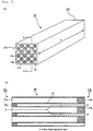
- Fig. 1 is a perspective view that schematically shows one example of a honeycomb filter according to the present invention.
- Fig. 2 (a) is a perspective view that schematically shows one example of a honeycomb fired body forming a honeycomb structured body of the honeycomb filter according to the present invention, and
- Fig. 2 (b) is an A-A line cross-sectional view of the honeycomb fired body shown in Fig. 2(a) .
- a honeycomb filter 1 of the present invention shown in Fig. 1 includes a honeycomb structured body 10 and a zeolite (not shown) supported on cell walls of the honeycomb structured body 10.
- the honeycomb structured body 10 will be first described.
- the honeycomb structured body 10 shown in Fig. 1 includes a ceramic block in which a plurality of honeycomb fired bodies 20 made of materials including silicon carbide are bonded with one another with an adhesive layer 14 interposed therebetween.
- a coat layer 13 is formed on the periphery of the ceramic block.
- the coat layer is optionally formed depending on needs.
- a honeycomb structured body which is formed of a plurality of honeycomb fired bodies bonded with one another with an adhesive layer interposed therebetween is also referred to as an aggregated honeycomb structured body.
- a honeycomb fired body 20 shown in Figs. 2 (a) and 2 (b) includes a large number of cells placed in parallel with each other in the longitudinal direction (shown by a double-sided arrow "a" in Fig. 2(a) ) of the honeycomb fired body 20.
- the large number of cells include a large volume cell 21a and a small volume cell 21b having different shapes from one another.
- the large volume cell 21a is open at an end portion on a first end face 22a side (1a side of the first end face of the honeycomb filter) of the honeycomb fired body 20 and is sealed with a sealing material 23b at an end portion on a second end face 22b side (1b side of the second end face of the honeycomb filter) of the honeycomb fired body 20.
- the small volume cell 21b is open at an end portion on the second end face 22b side of the honeycomb fired body 20 and is sealed with a sealing material 23a at an end portion on the first end face 22a side of the honeycomb fired body 20. Therefore, when the honeycomb filter 1 is used for a urea SCR device, exhaust gases G (in Fig.
- the zeolite supported on the cell wall 24 of the honeycomb structured body 10 functions as a catalyst for catalytic reduction which acts on NOx in combination with a reducing agent such as ammonia to reduce NOx into N 2 . Therefore, when the honeycomb filter 1 is used for a urea SCR device, NOx in exhaust gases is reduced to N 2 by the action of the zeolite supported on the cell wall 24 and the action of ammonia derived from urea water sprayed from a urea spray nozzle of the urea SCR device while the exhaust gases pass through the cell wall 24.
- the thermal conductivity of the cell wall 24 supporting the zeolite is 5 to 10 W/mK, allowing the honeycomb filter 1 to have a sufficiently high heat dissipation capability. Therefore, when exhaust gases are purified by a urea SCR device including the honeycomb filter 1, PM burning heat generated in regeneration process is efficiently dissipated from the honeycomb filter 1. The honeycomb filter 1 is thus not exposed to the sintering temperature for a long period of time, thereby preventing deactivation of the zeolite. Accordingly, even in the case of repeating regeneration process, the NOx conversion rate can be kept at a high level.
- the porosity of the honeycomb structured body 10 in which zeolite is not supported is 55 to 65%.
- the porosity of the honeycomb structured body is less than 55%
- pores of the cell wall may be clogged with the zeolite, making it difficult for exhaust gases to pass through the cell wall.
- NOx cannot be sufficiently converted, and further the pressure loss is increased.
- the porosity of the honeycomb structured body exceeds 65%, when a plurality of pores having a predetermined pore diameter are formed, the ratio of the pores forming the cell wall becomes too high. Therefore, the thermal conductivity of the cell wall supporting zeolite tends to be low, thereby deteriorating the heat dissipation capability of the honeycomb filter. Moreover, the strength of the honeycomb structured body (honeycomb filter) is reduced.
- the amount of the zeolite supported on the cell wall 24 of the honeycomb structured body 10 is 80 to 150 g/L, and thus the zeolite is supported on the cell wall in an amount sufficient for reducing NOx.
- the amount of the zeolite supported on the cell wall of the honeycomb structured body is less than 80 g/L, the amount of the zeolite supported on the cell wall is too small to sufficiently convert NOx.
- the honeycomb filter 1 according to Claim 1 can have PM capturing effect and also have a high NOx conversion rate even after repeating regeneration process.
- the honeycomb filter according to Claim 1 has the thermal conductivity of 5 to 10 W/mK. Therefore, the heat dissipation capability of the honeycomb filter is higher so that PM burning heat generated in regeneration process is more efficiently dissipated from the honeycomb filter. Therefore, the honeycomb filter can be prevented from being exposed to the sintering temperature in regeneration process.
- the large number of cells include a large volume cell and a small volume cell, and an area ratio of a cross sectional area of the large volume cell perpendicular to the longitudinal direction relative to a cross sectional area of the small volume cell perpendicular to the longitudinal direction is 1.4 to 2.4.
- the honeycomb filter may be placed in a casing in a manner that inlet-side cells for introducing exhaust gases include the large volume cells and outlet-side cells for discharging exhaust gases include the small volume cells. The surface area of the inlet-side cells can thus be larger.
- the thickness of the accumulated PM laver can be made thinner than that of a honeycomb structured body (honeycomb filter) in which a total of the surface area of the gas-inlet side cells is the same as a total of the surface area of the gas-outlet side cells. Consequently, it is possible to inhibit an increase in the pressure loss or to increase the maximum PM capturing amount. Further, in a case of capturing a given amount of PM, the honeycomb filter of the present invention has a thinner PM accumulating layer and thus the PM can be easily burned. It is thus possible to reduce the frequency of regeneration and to shorten the time for the honeycomb filter to be exposed to a sintering temperature.
- a cross section of the large volume cell perpendicular to the longitudinal direction has a substantially octagonal shape
- a cross section of the small volume cell perpendicular to the longitudinal direction has a substantially quadrangular shape
- a cross section of the large volume cell perpendicular to the longitudinal direction has a substantially quadrangular shape
- a cross section of the small volume cell perpendicular to the longitudinal direction has a substantially quadrangular shape
- honeycomb filters having the cells with the aforementioned shapes can preferably enjoy the effects of the honeycomb filter of the present invention.
- the zeolite is at least one species selected from the group consisting of a ⁇ -type zeolite, a ZSM-5 type zeolite, and a SAPO.
- the zeolite is ion-exchanged with a copper ion and/or an iron ion.
- the honeycomb structured body includes a plurality of honeycomb fired bodies combined with one another with an adhesive layer interposed therebetween.
- the honeycomb filter of the present embodiment includes a honeycomb structured body and a zeolite supported on the cell wall of the honeycomb structured body.
- the honeycomb structured body of the present embodiment is an aggregated honeycomb structured body.
- a coat layer 13 is formed on the periphery of a honeycomb structured body 10 (ceramic block formed of a plurality of honeycomb fired bodies 20 bonded with one another with an adhesive layer interposed therebetween) for preventing leak of exhaust gases or preventing damage of the honeycomb structured body 10.
- the coat layer 13 contains inorganic fibers such as alumina, inorganic particles such as silicon carbide, an inorganic binder such as silica sol, an organic binder such as carboxymethyl cellulose, and the like.
- the large number of cells in the honeycomb fired body 20 shown in Fig. 2 (a) include the large volume cell 21a having a relatively larger cross-sectional area perpendicular to the longitudinal direction thereof (direction of the double-sided arrow "a" in Fig. 2 (a) ) than the small volume cell 21b, and the small volume cell 21b having a relatively smaller cross-sectional area perpendicular to the longitudinal direction thereof than the large volume cell 21a.
- the large volume cell 21a has a substantially octagonal shape in the cross section perpendicular to the longitudinal direction of the honeycomb fired body 20.
- the small volume cell 21b has a substantially quadrangular shape in the cross section perpendicular to the longitudinal direction of the honeycomb fired body 20.
- the area ratio of the cross-sectional area of the large volume cell 21a perpendicular to the longitudinal direction relative to the cross-sectional area of the small volume cell 21b perpendicular to the longitudinal direction is 1.4 to 2.4.
- the first end face 22a of the honeycomb fired body 20 forms the first end face 1a of the honeycomb filter 1
- the second end face 22b of the honeycomb fired body 20 forms the second end face 1b of the honeycomb filter 1.
- the porosity of a honeycomb structured body in which zeolite is not supported on the cell wall is 55 to 65%.
- the porosity of the cell wall of the honeycomb structured body refers to a porosity of the cell wall of the honeycomb structured body which does not support a zeolite.
- the porosity can be measured through a conventionally known method such as a mercury porosimetry method, Archimedes method, a weighing method, and a measuring method using a scanning electronic microscope (SEM).
- the amount of the zeolite supported on the cell wall of the honeycomb structured body is 80 to 150 g/L.
- the amount of the zeolite supported on the cell wall of the honeycomb structured body refers to the weight of zeolite per one liter apparent volume of the honeycomb structured body.
- the apparent volume of the honeycomb structured body includes the volume of adhesive layers and further includes the volume of a coat layer when a coat layer is formed.
- the thermal conductivity of the cell wall supporting a zeolite is 5 to 10 W/mK, and is preferably 5.1 to 10.0 W/mK. Reasons for this are described earlier, and thus explanation is omitted.
- the thermal conductivity in this Description refers to a thermal conductivity obtained by a laser flash method.
- the species of the zeolite is not particularly limited as long as it can reduce NOx, and examples of the zeolite include ⁇ -type zeolite, Y-type zeolite, ferrierite, ZSM-5 type zeolite, mordenite, faujasite, A-type zeolite, L-type zeolite, SAPO (Silicoaluminophosphate), MeAPO (Metalaluminophosphate), and the like. Each of these may be used alone or two or more kinds of these may be used in combination. At least one species selected from the group consisting of ⁇ -type zeolite, ZSM-5 type zeolite, and SAPO is preferable among the above zeolites.
- a zeolite includes not only aluminosilicate but analogues of zeolite such as aluminophosphate as well.
- the zeolite may be ion-exchanged with metal ions.
- the metal ions include copper ion, iron ion, nickel ion, zinc ion, manganese ion, cobalt ion, silver ion, vanadium ion, and the like. Each of these may be used alone or two or more kinds of these may be used in combination.
- zeolite is ion-exchanged with a copper ion and/or iron ion.
- a wet mixture for manufacturing a molded body is prepared by mixing silicon carbide powders having different average particle diameters as a ceramic material, an organic binder, a pore forming agent, a liquid plasticizer, a liquid lubricant, and water.
- the average particle diameter of the coarse powder of the silicon carbide and the fine powder of the silicon carbide, particle diameter of the pore forming agent, and blending ratio of each material are properly controlled so that a honeycomb structured body to be prepared has a porosity of 55 to 65%.
- the wet mixture is introduced into an extrusion molding apparatus and then extrusion-molded so as to manufacture a honeycomb molded body having a predetermined shape.
- a honeycomb molded body is manufactured by using a die which can form a honeycomb molded body in which a large volume cell having a substantially octagonal shape and a larger area in the cross section perpendicular to the longitudinal direction and a small volume cell having a substantially quadrangular shape and a smaller area in the cross section perpendicular to the longitudinal direction are alternately disposed, and the area ratio of the cross-sectional area of the large volume cell perpendicular to the longitudinal direction relative to the cross-sectional area of the small volume cell perpendicular to the longitudinal direction in the honeycomb molded body is adjusted to be in a predetermined range.
- honeycomb molded body Next, cutting of both ends of the honeycomb molded body with a cutting apparatus is performed to cut the honeycomb molded body into a predetermined length.
- the cut honeycomb molded body is dried with a drying apparatus to manufacture a honeycomb dried body.
- One end of each of the large volume cells and one end of each of the small volume cells of the manufactured honeycomb dried body are filled in with a predetermined amount of a sealing material paste which is to be a sealing material and has the same composition as that of the wet mixture, thereby sealing the cells.
- sealing is performed so that the large volume cell is sealed at an end portion on the second end face side of the honeycomb fired body, and the small volume cell is sealed at an end portion on the first end face side of the honeycomb fired body in a honeycomb fired body manufactured through the below-mentioned process.
- the cell-sealed honeycomb molded body is heated in a degreasing furnace to remove organic matters such as an organic binder contained in the cell-sealed honeycomb molded body to manufacture a honeycomb degreased body.
- the manufactured honeycomb degreased body is transported to a firing furnace and is then fired under argon atmosphere at 2000 to 2300°C for 1 to 10 hours.
- a honeycomb fired body having a shape shown in Fig. 2 (a) and Fig. 2(b) is manufactured. Namely, a substantially quadrangular pillar-shaped honeycomb fired body having large volume cells and small volume cells, with either one end of each of the cells sealed is manufactured.
- honeycomb fired bodies each having substantially the same shape as that mentioned earlier are manufactured.
- a zeolite may be supported on the cell wall of the honeycomb fired bodies by performing the below-mentioned zeolite supporting process on the honeycomb fired bodies.
- binding is performed by applying an adhesive paste between the honeycomb fired bodies (or honeycomb fired body in which a zeolite is supported on the cell wall thereof, hereinafter the same) to form an adhesive paste layer and then by drying and solidifying the adhesive paste layer to form an adhesive layer. Accordingly, a substantially quadrangular pillar-shaped ceramic block in which a plurality of the honeycomb fired bodies are bonded with one another with an adhesive layer interposed therebetween is manufactured.
- the plurality of the honeycomb fired bodies are arranged so that the first end faces of the respective honeycomb fired bodies are disposed on the same side, and then the honeycomb fired bodies are bonded with one another.
- the adhesive paste to be preferably used is an adhesive paste including inorganic fibers and/or whiskers, an inorganic binder, and an organic binder.
- Periphery cutting is carried out by cutting the periphery of the substantially quadrangular pillar-shaped ceramic block with a diamond cutter so as to provide a substantially round pillar-shaped ceramic block.
- the substantially round pillar-shaped ceramic block is used as a honeycomb structured body according to the present invention.
- Coating layer forming is performed by applying a coating material paste on the periphery of the substantially round pillar-shaped ceramic block and drying and solidifying the coating material paste with a hot air drying apparatus or the like to form a coat layer.
- a coating material paste a paste that is the same as the adhesive paste may be used.
- a predetermined amount of a zeolite is suspended in water to prepare a zeolite slurry.
- honeycomb structured body is dipped in the above-obtained zeolite slurry and is taken out from the slurry. Then, the resulting honeycomb structured body is heated and fired so that the zeolite is supported on the cell wall of the honeycomb structured body.
- the amount of the zeolite to be supported on the cell wall of the honeycomb structured body is controlled to be 80 to 150 g/L.
- the amount of the zeolite can be controlled by, for example, changing the concentration of the slurry, changing the number of times of repeating the dipping into slurry and the heating, and the like.
- a honeycomb filter in which a zeolite is supported on the cell wall of the honeycomb structured body is manufactured.
- the pressure loss can be prevented from increasing, or the maximum PM capturing amount can be increased. Furthermore, since the thickness of the accumulated PM layer can be decreased, burning of PM, can be accelerated.
- an organic binder methylcellulose
- a pore-forming agent hinder acrylic particles having an average particle diameter of 21 ⁇ m
- a lubricant UNILUB, made by NOF Corporation
- glycerin glycerin
- the wet mixture was introduced to an extrusion-molding apparatus and extrusion-molded so that a quadrangular pillar-shaped honeycomb molded body as shown in Fig. 2 (a) and Fig. 2(b) , which includes large volume cells each having a substantially octagonal shape in a cross sectional view and small volume cells each having a substantially quadrangular shape in a cross sectional view, with the cells not sealed, was manufactured.
- the honeycomb molded body was cut into a predetermined length.
- the cut honeycomb molded body was dried by a micro wave drying apparatus so that a honeycomb dried body was manufactured.
- One end of each of the large volume cells and one end of each of the small volume cells of the manufactured honeycomb dried body were filled in with a predetermined amount of a sealing material paste which was to be a sealing material and had the same composition as that of the wet mixture to seal the cells so that a cell-sealed honeycomb molded body was manufactured.
- sealing is performed so that the large volume cell is sealed at an end portion on the second end face side of the honeycomb fired body, and the small volume cell is sealed at an end portion on the first end face side of the honeycomb fired body in a honeycomb fired body manufactured through the below-mentioned process.
- the cell-sealed honeycomb molded body was heated at 400°C in a degreasing furnace to remove organic matters such as an organic binder contained in the cell-sealed honeycomb molded body to manufacture a honeycomb degreased body.
- honeycomb degreased body was transported to a firing furnace and was then fired under argon atmosphere at 2250°C for 5 hours.
- a substantially quadrangular pillar-shape honeycomb fired body as shown in Fig. 2 (a) and Fig. 2 (b) which includes large volume cells each having a substantially octagonal cross-sectional shape perpendicular to the longitudinal direction and small volume cells each having a substantially quadrangular cross-sectional shape perpendicular to the longitudinal direction, with either one end of each of the cells sealed, was manufactured.
- honeycomb fired body had a size of 34.3 mm x 34.3 mm x 150 mm.
- An area ratio of a cross sectional area of the large volume cell perpendicular to the longitudinal direction relative to a cross sectional area of the small volume cell perpendicular to the longitudinal direction was 1.55.
- the porosity of the honeycomb fired body was 60%.
- the porosity was measured by a weighing method.
- the above-manufactured honeycomb fired body is categorized as Type 1.
- An adhesive paste was applied between the honeycomb fired bodies to form adhesive paste layers, and the adhesive paste layers were dried and solidified to form adhesive layers. Accordingly, a ceramic block having a substantially quadrangular pillar shape in which sixteen pieces of the honeycomb fired bodies were bonded with one another with the adhesive layer interposed therebetween was manufactured.
- the plurality of the honeycomb fired bodies were bonded with one another in a manner that the first end faces of the respective honeycomb fired bodies were arranged on the same side.
- an adhesive paste containing 30% by weight of alumina fiber having an average fiber length of 20 ⁇ m, 21% by weight of silicon carbide powder having an average particle diameter of 0.6 ⁇ m, 15% by weight of silica sol (solid content 30%by weight), 5.6% by weight of carboxymethyl cellulose, and 28.4% by weight of water was used.
- a coating material paste was applied on the periphery of the round pillar-shaped ceramic block, and the coating material paste was dried and solidified at a temperature of 120°C so that a coat layer was formed on the periphery of the ceramic block.
- the coating material paste the same paste as the aforementioned adhesive paste was used.
- a sufficient amount of water was mixed with ⁇ -type zeolite powder (average particle diameter: 2 ⁇ m) ion-exchanged with an iron ion and then stirred to prepare a zeolite slurry.
- the honeycomb structured body was dipped in the zeolite slurry with one end side facing down for one minute.
- the resulting honeycomb structured body was dried at 110°C for one hour, and further fired at 700°C for one hour so that the zeolite was supported on the cell wall of the honeycomb structured body.
- honeycomb filter in which the zeolite was supported on the cell wall of the honeycomb structured body was manufactured.
- the thermal conductivity of the cell wall supporting the zeolite in the honeycomb filter was measured by a laser flash method (according to JIS R 1611 (2007) and JIS R 1650-3 (2002)).
- a holding sealing material was wound around the periphery of the honeycomb filter manufactured in the above zeolite supporting process.
- the resulting honeycomb filter was press-fitted into a cylindrical casing so that an exhaust gas purifying apparatus was manufactured.
- the end portion on the exhaust gas inlet side of the exhaust gas purifying apparatus was connected to an introduction pipe coupled to a 2L common-rail-type diesel engine. Further, the end portion on the exhaust gas outlet side of the exhaust gas purifying apparatus was connected to an exhaust pipe coupled to the outside.
- the engine was driven at the number of revolutions of 2000 min -1 and a torque of 47 Nm so that exhaust gases from the engine were allowed to pass through the honeycomb filter.
- PM was burned in a post-injection method to carry out regeneration of the honeycomb filter.
- the regenerated honeycomb filter was cut by a diamond cutter to produce a single honeycomb fired body (34.3 mm ⁇ 34.3 mm ⁇ 150 mm).
- the cut-out honeycomb fired body was further cut shortened to manufacture a short-length body in a size of 34.3 mm ⁇ 34.3 mm ⁇ 40 mm .
- cells of the short-length body were sealed with the adhesive paste in a manner that one end of each of the cells was sealed, and the cell-sealed short-length body was degreased at 400°C so that a sample for measuring NOx conversion rate was manufactured.
- the NOx conversion rate was measured with a NOx conversion rate-measuring apparatus (Catalyst test system SIGU-2000, product of HORIBA, Ltd.).
- the NOx conversion rate-measuring apparatus includes a gas generator and a reactor.
- a simulated exhaust gas generated by the gas generator was passed through the reactor in which the sample for measuring NOx conversion rate was placed.
- Composition of the simulated exhaust gas includes NO:175ppm, NO 2 :175ppm, NH 3 :350ppm, O 2 :14%, CO 2 :5%, H 2 O:10%, and N 2 :balance. This composition was obtained by controlling each the amount of the gas flow rate with a flow rate controller.
- the temperature of the reactor was fixed at 200°C.
- the space velocity (SV) was set at 70000 hr -1 .
- NOx conversion rate % N 0 ⁇ N 1 / N 0 ⁇ 100
- a honeycomb filter and a sample for measuring NOx conversion rate were manufactured in the same manner as those in Example 1, except that the amount of the zeolite supported on the cell wall of the honeycomb structured body was set to 120 g/L.
- the honeycomb fired body manufactured in Example 2 was the same as the honeycomb fired body manufactured in Example 1 and was thus Type 1.
- Honeycomb filters and samples for measuring NOx conversion rate were manufactured in the same manner as those in Example 1, except that the porosities of the honeycomb fired bodies were changed by altering the particle diameter of each powder to be blended, the blending ratios, and other factors as shown in Table 1 and that the zeolite supporting amount was changed as shown in Table 2.
- the amount of the zeolite to be supported was controlled by appropriately repeating dipping of the honeycomb structured body into the zeolite slurry, the drying, and the firing so that a predetermined amount of zeolite was supported per one liter apparent volume of the honeycomb structured body.
- honeycomb fired bodies manufactured in Examples 3, 4, and Comparative Example 5 are the same, and those honeycomb fired bodies are categorized as Type 2.
- the honeycomb fired body manufactured in Example 5 is categorized as Type 5, and the honeycomb fired body manufactured in Comparative Example 3 was categorized as Type 6.
- the honeycomb fired body manufactured in Reference Example 6 was categorized as Type 3.
- the conditions for manufacturing the honeycomb fired bodies in Comparative Examples 1 and 2 are the same, and those honeycomb fired bodies are categorized as Type 4.
- the honeycomb fired body manufactured in Comparative Example 4 is Type 1.
- Table 1 collectively shows blending ratios of the materials of the wet mixture, firing conditions, types and porosity of the honeycomb fired bodies manufactured in each Example, Reference Example and each Comparative Example.
- Type of Honey comb fired body Silicon carbide (coarse powder) Silicon carbide (the powder) Methylcellulose Hollow acrylic particle UNI LUB Glycerin Water Firing condition Porosity (%) Particle diameter ( ⁇ m) Blending ratio (%by weig ht) Particle diameter ( ⁇ m) Blending ratio (%by weight) Blending ratio (%by weight) Particle diameter ( ⁇ m) Blen ding ratio (%by weight) Blen ding ratio (%b y weight) Blending ratio (%by weight) Blending ratio (%by weight) Blending ratio (%by weight) Temperature (°C) Time (hr) Type 1 24 46.6 0.5 20.0 3.8 21 6.8 3.5 1.6 17.4 2250 5 60 Type 2 28 45.7 0.5 19.7 3.7 25 8.5 3.4 1.8 17.4 2250 5 65 Type
- Example 2 The thermal conductivity and the NOx conversion rate after the regeneration process were measured for the honeycomb filters and the samples for measuring NOx conversion rate manufactured in Examples 2 to 5, Reference Example 6 and Comparative Example 1 to 5 in the same manner as in Example 1. Further, the porosity of the honeycomb fired bodies (Type 1 to Type 6) was measured in the same manner as in Example 1. Table 2 showed the results.
- Table 2 shows that the NOx conversion rate after regeneration process is high when the honeycomb filter of the present invention satisfies the structure (1) : the porosity of the honeycomb strcutured body is 55 65%; the structure (2): the amount of the zeolite supported on the cell wall of the honeycomb structured body is 80 to 150 g/L; and the structure (3): the thermal conductivity of the cell wall supporting the zeolite is 3 W/mK or more.
- the honeycomb structured body forming the honeycomb filter includes a single honeycomb fired body.
- the honeycomb structured body including a single honeycomb fired body is also referred to as an integral honeycomb structured body.
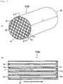
- Fig. 3(a) is a perspective view that schematically shows one example of the honeycomb filter of the present invention
- Fig. 3(b) is a B-B line cross-sectional view of the honeycomb filter shown in Fig. 3(a) .
- the honeycomb filter 79 shown in Fig. 3(a) includes a honeycomb structured body 80 made of materials including silicon carbide, and a zeolite (not shown) supported on the cell wall of the honeycomb structured body 80.
- a honeycomb filter 79 (honeycomb structured body 80) has a substantially round pillar shape including a first end face 84 and a second end face 85, and has a large volume cell 91a having a relatively larger cross-sectional area perpendicular to the longitudinal direction thereof (direction of the double-sided arrow "b" in Fig. 3(a) ) than a small volume cell 91b, and the small volume cell 91b having a relatively smaller cross-sectional area perpendicular to the longitudinal direction than the large volume cell 91a.
- the large volume cell 91a has a substantially octagonal shape in the cross section perpendicular to the longitudinal direction thereof.
- the small volume cell 91b has a substantially quadrangular shape in the cross section perpendicular to the longitudinal direction thereof.
- a coat layer 82 was formed on the periphery of the honeycomb structured body 80.
- the large volume cell 91a is open at an end portion on the first end face 84 side of the honeycomb structured body 80 and is sealed with a sealing material 92a at an end portion on the second end face 85 side of the honeycomb structured body 80.
- the small volume cell 91b is open at an end portion on the second end face 85 side of the honeycomb structured body 80 and is sealed with a sealing material 92b at an end portion on the first end face 84 side of the honeycomb structured body 80.
- a cell wall 93 interposed between the large volume cell 91a and the small volume cell 91b functions as a filter.
- exhaust gases introduced to the large volume cell 91a surely pass through the cell wall 93 and then flow out from the small volume cell 91b.
- the thermal conductivity of the cell wall 93 supporting the zeolite is 5 to 10 W/mK, and thus the heat dissipation capability of the honeycomb filter 79 is sufficiently high. For this reason, the honeycomb filter 79 is not exposed to the sintering temperature for a long period of time in regeneration process, and thus a high NOx conversion rate can be maintained. Moreover, since the porosity of the honeycomb structured body 80 in a condition where a zeolite is not supported on the cell wall 93 is 55 to 65%, NOx can be sufficiently converted, and the pressure loss can be decreased. Also, the strength of the honeycomb filter 79 is high.
- the amount of the zeolite supported on the cell wall of the honeycomb structured body 80 is 80 to 150 g/L, NOx can be sufficiently converted and also the pressure loss can be decreased.
- kinds of the zeolite are the same as those of the first embodiment.
- An area ratio of a cross sectional area of the large volume cell perpendicular to the longitudinal direction relative to a cross sectional area of the small volume cell perpendicular to the longitudinal direction is 1.4 to 2.4.
- the honeycomb molded body is manufactured in the same manner as in the first embodiment, except that the honeycomb molded body manufactured by extrusion molding is larger than and in a different outer shape from the honeycomb molded body described in the first embodiment.
- honeycomb structured body forming the honeycomb filter has a single honeycomb fired body in the present embodiment, bonding is not necessary.
- the periphery cutting is not necessary.
- the thus manufactured honeycomb filter may be used for a urea SCR device.
- the honeycomb filter of the present embodiment can exert the same effects as the effects (1) to (4) according to the first embodiment.
- the thickness of the cell wall of the honeycomb structured body (honeycomb fired body) forming the honeycomb filter of the present invention is not particularly limited, and is preferably 0.2 to 0.4 mm.
- honeycomb fired body When the thickness of the cell wall of the honeycomb structured body (honeycomb fired body) is 0.2 to 0.4 mm, NOx can be sufficiently converted. Moreover, the strength of the honeycomb filter can be sufficiently increased.
- the thickness exceeding 0.4 mm may cause an increase in pressure loss.
- the cell density on a cross section perpendicular to the longitudinal direction of the honeycomb filter is not particularly limited.
- a desirable lower limit is 31 pcs/cm 2 (200 pcs/in 2 ) and a desirable upper limit is 93 pcs/cm 2 (600 pcs/in 2 ).
- a more desirable lower limit is 46.5 pcs/cm 2 (300 pcs/in 2 ) and a more desirable upper limit is 62 pcs/cm 2 (400 pcs/in 2 )
- the cell density in a range of 31 pcs/cm 2 to 93 pcs/cm 2 improves the NOx conversion rate.
- the shape of the (honeycomb filter is not limited to a substantially round pillar shape, and may be optional pillar shapes such as a substantially cylindroid shape and a substantially polygonal pillar shape.
- the average pore diameter of the honeycomb fired body forming the aggregated honeycomb structured body and the average pore diameter of the integral honeycomb structured body are preferably 5 to 30 ⁇ m.
- the average pore diameter is less than 5 ⁇ m, clogging of the pores with particulates may occur easily.
- the average pore diameter is more than 30 ⁇ m, particulates may pass through the pores and are not captured. Therefore the honeycomb structured body cannot function as a filter.
- the particle diameter of the ceramic powder to be used in manufacturing the honeycomb fired bodies forming the aggregated honeycomb structured body and the integral honeycomb structured body is not particularly limited, and the ceramic powder that tends not to cause the case where the size of the honeycomb fired body manufactured by the subsequent firing process becomes smaller than that of a degreased honeycomb molded body manufactured through the degreasing is preferable.
- a powder including a combination of 100 parts by weight of powder having an average particle diameter of 1.0 to 50 ⁇ m, and 5 to 65 parts by weight of powder having an average particle diameter of 0.1 to 1.0 ⁇ m is preferable.
- the organic binder in the wet mixture to be used in manufacturing the honeycomb fired bodies forming the aggregated honeycomb structured body and the integral honeycomb structured body is not particularly limited, and examples thereof include methyl cellulose, carboxy-methyl cellulose, hydroxyethyl cellulose, polyethylene glycol, and the like. Methylcellulose is preferable among the above examples.
- the blending amount of the organic binder is desirably 1 to 10 parts by weight with respect to 100 parts by weight of the ceramic powder.
- the plasticizer to be contained in the wet mixture is not particularly limited, and examples thereof include glycerin or the like as mentioned earlier.
- the lubricant to be contained in the wet mixture is not limited, and examples thereof include polyoxy alkylene-based compounds such as polyoxyethylene alkyl ether and polyoxypropylene alkyl ether, and the like. Specific examples of the lubricant include polyoxyethylene monobutyl ether, polyoxypropylene monobutyl ether, and the like.
- the plasticizer and the lubricant are not necessarily contained in the wet mixture depending on cases.
- a dispersant solution may be used, and examples of the dispersant solution include water, an organic solvent such as benzene, alcohol such as methanol, and the like.
- a molding auxiliary may be added to the wet mixture.
- the molding auxiliary is not particularly limited, and examples thereof include ethylene glycol, dextrin, fatty acid, fatty acid soap, polyalcohol, and the like.
- balloons that are fine hollow spheres including an oxide based ceramic, or spherical acrylic particles, graphite or the like may be optionally added to the wet mixture.
- the balloons are not particularly limited, and examples thereof include, alumina balloons, glass micro-balloons, shirasu balloons, fly ash balloons (FA balloons), mullite balloons, and the like. Out of these, alumina balloons are more desirably used.
- the zeolite may be supported on a honeycomb structured body as mentioned earlier or may be supported on a honeycomb fired body.
- an aggregated honeycomb structured body can be manufactured by allowing the honeycomb fired bodies to support zeolite as mentioned earlier and then combining the honeycomb fired bodies supporting zeolite with one another with the adhesive layer interposed therebetween.
Landscapes
- Physics & Mathematics (AREA)
- Geometry (AREA)
- Chemical & Material Sciences (AREA)
- Chemical Kinetics & Catalysis (AREA)
- Thermal Sciences (AREA)
- Catalysts (AREA)
- Exhaust Gas Treatment By Means Of Catalyst (AREA)
- Filtering Materials (AREA)
- Exhaust Gas After Treatment (AREA)
Claims (7)
- Filtre nid d'abeille comprenant :un corps structuré en nid d'abeille disposant d'un grand nombre de cellules chacune fermée hermétiquement à ses deux extrémités et placées longitudinalement parallèlement les unes aux autres avec une paroi cellulaire entre elles etun zéolite supporté sur la paroi cellulaire du corps structure en nid d'abeille,dans lequelle corps structuré en nid d'abeille contient du carbure de silicium,une porosité de la paroi cellulaire du corps structuré en nid d'abeille est comprise entre 55% et 65%,une quantité du zéolite supporté sur la paroi cellulaire est comprise entre 80 et 150 g/L, etune conductivité thermique de la paroi cellulaire supportant le zéolite est 5 à 10 W/mK.
- Filtre nid d'abeille selon la revendication 1, dans lequel
les plusieurs cellules comprennent une cellule à grand volume et une cellule à petit volume, et
un rapport des surfaces d'une surface en coupe de la cellule à grand volume perpendiculaire à la direction longitudinale par une surface en coupe de la cellule à petit volume perpendiculaire à la direction longitudinale est compris entre 1,4 et 2,4. - Filtre nid d'abeille selon la revendication 2, dans lequel
une section en coupe de la cellule à grand volume perpendiculaire à la direction longitudinale a une forme sensiblement octogonale,
une section en coupe de la cellule à petit volume perpendiculaire à la direction longitudinale a une forme sensiblement quadrangulaire. - Filtre nid d'abeille selon la revendication 2, dans lequel
une section en coupe de la cellule à grand volume perpendiculaire à la direction longitudinale a une forme sensiblement quadrangulaire,
une section en coupe de la cellule à petit volume perpendiculaire à la direction longitudinale a une forme sensiblement quadrangulaire. - Filtre nid d'abeille selon l'une quelconque des revendications 1 à 4,
dans lequel le zéolite est au moins une espèce sélectionnée à partir du groupe constitué d'un zéolite β, d'un zéolite ZSM 5, et d'un SAPO. - Filtre nid d'abeille selon l'une quelconque des revendications 1 à 5,
dans lequel le zéolite entreprend un échange d'ion avec un ion de cuivre et/ou un ion de fer. - Filtre nid d'abeille selon l'une quelconque des revendications 1 à 6,
dans lequel le corps structuré en nid d'abeille comprend plusieurs corps cuits en nid d'abeille combinés entre eux une couche adhésive étant interposée entre eux.
Priority Applications (1)
| Application Number | Priority Date | Filing Date | Title |
|---|---|---|---|
| PL10156879T PL2319604T3 (pl) | 2009-10-09 | 2010-03-18 | Filtr o strukturze plastra miodu |
Applications Claiming Priority (1)
| Application Number | Priority Date | Filing Date | Title |
|---|---|---|---|
| PCT/JP2009/067671 WO2011042990A1 (fr) | 2009-10-09 | 2009-10-09 | Filtre en nid d'abeille |
Publications (3)
| Publication Number | Publication Date |
|---|---|
| EP2319604A1 EP2319604A1 (fr) | 2011-05-11 |
| EP2319604B1 EP2319604B1 (fr) | 2012-05-09 |
| EP2319604B2 true EP2319604B2 (fr) | 2018-12-26 |
Family
ID=42204372
Family Applications (1)
| Application Number | Title | Priority Date | Filing Date |
|---|---|---|---|
| EP10156879.8A Active EP2319604B2 (fr) | 2009-10-09 | 2010-03-18 | Wabenfilter |
Country Status (7)
| Country | Link |
|---|---|
| US (1) | US8617476B2 (fr) |
| EP (1) | EP2319604B2 (fr) |
| AT (1) | ATE556757T1 (fr) |
| DE (1) | DE202010018192U1 (fr) |
| ES (1) | ES2387068T3 (fr) |
| PL (1) | PL2319604T3 (fr) |
| WO (1) | WO2011042990A1 (fr) |
Families Citing this family (10)
| Publication number | Priority date | Publication date | Assignee | Title |
|---|---|---|---|---|
| WO2012046292A1 (fr) | 2010-10-04 | 2012-04-12 | イビデン株式会社 | Procédé pour la fabrication d'une structure en nid-d'abeilles |
| WO2012131916A1 (fr) * | 2011-03-29 | 2012-10-04 | イビデン株式会社 | Structure en nid d'abeilles et procédé de fabrication d'une structure en nid d'abeilles |
| JP5814373B2 (ja) * | 2011-08-18 | 2015-11-17 | イビデン株式会社 | ハニカム構造体及びその製造方法、排ガス浄化装置並びにシリコアルミノホスフェート粒子 |
| WO2013024547A1 (fr) * | 2011-08-18 | 2013-02-21 | イビデン株式会社 | Structure en nid d'abeilles, procédé de fabrication de celle-ci, dispositif de purification de gaz d'échappement et particules de silicoaluminophosphate |
| MX387698B (es) | 2012-10-19 | 2025-03-11 | Basf Mobile Emissions Catalysts Llc | Composiciones de catalizador de tamiz molecular de poro pequeño de 8 anillos de metales mezclados, artículos catalíticos y métodos. |
| GB2542654B (en) | 2015-06-28 | 2019-12-04 | Johnson Matthey Plc | Catalytic wall-flow filter having a membrane |
| GB2558371B (en) | 2016-10-28 | 2021-08-18 | Johnson Matthey Plc | Catalytic wall-flow filter with partial surface coating |
| EP3532196A1 (fr) | 2016-10-31 | 2019-09-04 | Johnson Matthey Public Limited Company | Catalyseurs lta comprenant du fer et/ou du manganèse extra-ossature pour le traitement de gaz d'échappement |
| JP6605522B2 (ja) * | 2017-03-09 | 2019-11-13 | 株式会社キャタラー | 排ガス浄化用触媒 |
| JP7342031B2 (ja) * | 2018-04-23 | 2023-09-11 | ビーエーエスエフ コーポレーション | ディーゼルエンジン排気ガス処理用の選択的接触還元触媒 |
Family Cites Families (42)
| Publication number | Priority date | Publication date | Assignee | Title |
|---|---|---|---|---|
| JPH01151706A (ja) * | 1987-12-08 | 1989-06-14 | Toyota Central Res & Dev Lab Inc | 可燃性微粒子と窒素酸化物を除去するための触媒及びフィルター |
| US4867954A (en) * | 1988-04-07 | 1989-09-19 | Uop | Catalytic reduction of nitrogen oxides |
| DE4226111A1 (de) * | 1992-08-07 | 1994-02-10 | Bayer Ag | Verwendung eines Katalysators zur Verringerung der Partikelmenge und/oder -größe im Dieselabgas |
| US5589147A (en) * | 1994-07-07 | 1996-12-31 | Mobil Oil Corporation | Catalytic system for the reducton of nitrogen oxides |
| JP2002089247A (ja) * | 2000-09-14 | 2002-03-27 | Ibiden Co Ltd | 排気ガス浄化システム |
| JP4652553B2 (ja) * | 2000-11-10 | 2011-03-16 | イビデン株式会社 | 触媒コンバータ及びその製造方法 |
| DE60118421T2 (de) | 2000-11-10 | 2006-08-17 | Ibiden Co., Ltd. | Abgaskatalysator, Verfahren zu seiner Herstellung und Halte-und Dichtungsmaterial für Katalysatoren |
| JP5189236B2 (ja) | 2001-07-25 | 2013-04-24 | 日本碍子株式会社 | 排ガス浄化用ハニカム構造体及び排ガス浄化用ハニカム触媒体 |
| JP4367683B2 (ja) * | 2001-10-09 | 2009-11-18 | 日本碍子株式会社 | ハニカムフィルター |
| JP4303599B2 (ja) | 2002-03-25 | 2009-07-29 | イビデン株式会社 | 排ガス浄化用フィルタ |
| JP2004016931A (ja) * | 2002-06-17 | 2004-01-22 | Nissan Motor Co Ltd | 排気ガス浄化触媒 |
| JP2004261664A (ja) * | 2003-02-28 | 2004-09-24 | Ngk Insulators Ltd | ハニカム構造体及びハニカム構造体押出し成形用口金 |
| JPWO2005002709A1 (ja) | 2003-06-23 | 2006-08-10 | イビデン株式会社 | ハニカム構造体 |
| KR100865058B1 (ko) * | 2003-06-23 | 2008-10-23 | 이비덴 가부시키가이샤 | 허니컴 구조체 |
| US7229597B2 (en) | 2003-08-05 | 2007-06-12 | Basfd Catalysts Llc | Catalyzed SCR filter and emission treatment system |
| JP4471622B2 (ja) | 2003-10-22 | 2010-06-02 | イビデン株式会社 | ハニカム構造体 |
| DE602004011971T3 (de) | 2003-10-20 | 2012-10-18 | Ibiden Co., Ltd. | Wabenstruktur |
| DE202004021782U1 (de) * | 2004-01-09 | 2010-12-30 | Emitec Gesellschaft Für Emissionstechnologie Mbh | Partikelfilter umfassend eine metallische Faserlage |
| US7393377B2 (en) | 2004-02-26 | 2008-07-01 | Ngk Insulators, Ltd. | Honeycomb filter and exhaust gas treatment apparatus |
| JP4673084B2 (ja) | 2004-02-26 | 2011-04-20 | 日本碍子株式会社 | ハニカムフィルタ及び排ガス処理装置 |
| GB0405015D0 (en) | 2004-03-05 | 2004-04-07 | Johnson Matthey Plc | Method of loading a monolith with catalyst and/or washcoat |
| US7959868B2 (en) | 2004-04-12 | 2011-06-14 | Toyota Jidosha Kabushiki Kaisha | Exhaust gas purifying apparatus |
| JP4347120B2 (ja) | 2004-04-12 | 2009-10-21 | トヨタ自動車株式会社 | 排ガス浄化装置 |
| US7867598B2 (en) * | 2005-08-31 | 2011-01-11 | Ngk Insulators, Ltd. | Honeycomb structure and honeycomb catalytic body |
| EP1935489A4 (fr) | 2005-08-31 | 2012-01-25 | Ngk Insulators Ltd | Corps de catalyseur en nid d'abeille et son procédé de production |
| US8119075B2 (en) * | 2005-11-10 | 2012-02-21 | Basf Corporation | Diesel particulate filters having ultra-thin catalyzed oxidation coatings |
| KR20080081940A (ko) * | 2005-12-01 | 2008-09-10 | 바스프 카탈리스트 엘엘씨 | 작은 올레핀 탄화수소 분자에 대한 열수 안정성ag-제올라이트 트랩 |
| JPWO2007066671A1 (ja) * | 2005-12-07 | 2009-05-21 | 日本碍子株式会社 | ハニカム構造体及びその製造方法 |
| EP1974791A4 (fr) | 2005-12-26 | 2010-08-11 | Ngk Insulators Ltd | Structure alvéolaire et son procédé de fabrication |
| KR20080102179A (ko) | 2006-02-10 | 2008-11-24 | 니뽄 가이시 가부시키가이샤 | 허니콤 세그먼트, 허니콤 구조체 및 그 제조 방법 |
| JP5469335B2 (ja) | 2006-02-22 | 2014-04-16 | 日本碍子株式会社 | 炭化珪素質多孔体及びその製造方法 |
| WO2007097161A1 (fr) | 2006-02-22 | 2007-08-30 | Ngk Insulators, Ltd. | Objet poreux à base de carbure de silicium et procédé de production correspondant |
| JP2007296514A (ja) * | 2006-04-07 | 2007-11-15 | Ngk Insulators Ltd | 触媒体とその製造方法 |
| US7576031B2 (en) * | 2006-06-09 | 2009-08-18 | Basf Catalysts Llc | Pt-Pd diesel oxidation catalyst with CO/HC light-off and HC storage function |
| CN101374590B (zh) | 2006-10-05 | 2011-12-21 | 揖斐电株式会社 | 蜂窝结构体 |
| JP5260982B2 (ja) | 2007-03-30 | 2013-08-14 | イビデン株式会社 | ハニカムフィルタ |
| BRPI0810133B1 (pt) * | 2007-04-26 | 2023-01-17 | Johnson Matthey Public Limited Company | Método para converter óxidos de nitrogênio de um gás em nitrogênio, sistema de escapamento para um motor de combustão interna de queima pobre veicular, e, aparelho |
| CN101952224B (zh) * | 2007-11-30 | 2013-08-21 | 康宁股份有限公司 | 沸石基蜂窝体 |
| US8591623B2 (en) | 2008-02-29 | 2013-11-26 | Corning Incorporated | Honeycomb manufacturing method using ground nut shells and honeycomb body produced thereby |
| JP2009262076A (ja) * | 2008-04-25 | 2009-11-12 | Nippon Soken Inc | 排ガス浄化フィルタ |
| WO2009141878A1 (fr) | 2008-05-20 | 2009-11-26 | イビデン株式会社 | Structure en nid d'abeilles |
| WO2009141897A1 (fr) * | 2008-05-20 | 2009-11-26 | イビデン株式会社 | Structure en nid d'abeille |
-
2009
- 2009-10-09 WO PCT/JP2009/067671 patent/WO2011042990A1/fr not_active Ceased
-
2010
- 2010-03-18 DE DE202010018192.5U patent/DE202010018192U1/de not_active Expired - Lifetime
- 2010-03-18 AT AT10156879T patent/ATE556757T1/de active
- 2010-03-18 EP EP10156879.8A patent/EP2319604B2/fr active Active
- 2010-03-18 PL PL10156879T patent/PL2319604T3/pl unknown
- 2010-03-18 ES ES10156879T patent/ES2387068T3/es active Active
- 2010-05-17 US US12/781,793 patent/US8617476B2/en active Active
Also Published As
| Publication number | Publication date |
|---|---|
| US8617476B2 (en) | 2013-12-31 |
| WO2011042990A1 (fr) | 2011-04-14 |
| EP2319604A1 (fr) | 2011-05-11 |
| DE202010018192U1 (de) | 2014-09-19 |
| ATE556757T1 (de) | 2012-05-15 |
| PL2319604T3 (pl) | 2012-09-28 |
| ES2387068T3 (es) | 2012-09-12 |
| EP2319604B1 (fr) | 2012-05-09 |
| US20110085942A1 (en) | 2011-04-14 |
Similar Documents
| Publication | Publication Date | Title |
|---|---|---|
| EP2319604B2 (fr) | Wabenfilter | |
| EP2441513B1 (fr) | Corps de catalyseur en nid d'abeille et son procédé de fabrication | |
| US7785695B2 (en) | Honeycomb structured body | |
| US7862781B2 (en) | Honeycomb structure and method for manufacturing honeycomb structure | |
| US7731774B2 (en) | Honeycomb structured body | |
| US8038955B2 (en) | Catalyst supporting honeycomb and method of manufacturing the same | |
| EP1847319A1 (fr) | Structure poreuse en nid d'abeille et appareil de purification des gaz d'échappement l' utilisant | |
| EP1785603A1 (fr) | Circuit d'épuration de gaz d'échappement | |
| US7947231B2 (en) | Honeycomb structure, method for manufacturing honeycomb structure, and exhaust gas purifying apparatus | |
| EP2737944B1 (fr) | Corps de catalyseur en nid d'abeille | |
| JPWO2006041174A1 (ja) | セラミックハニカム構造体 | |
| JP2011098337A (ja) | ハニカムフィルタ | |
| EP2319603B2 (fr) | Filtre en nids d'abeilles | |
| JP2011098336A (ja) | ハニカムフィルタ | |
| EP2319605B1 (fr) | Filtre en nids d'abeilles | |
| WO2011061835A1 (fr) | Structure en nid d'abeille et appareil de purification des gaz d'échappement | |
| WO2011061839A1 (fr) | Structure en nid d'abeille et appareil de purification des gaz d'échappement | |
| EP1808228A1 (fr) | Structure en nid d abeilles, procédé de production et dispositif de purification de gaz d échappement | |
| JP2011098338A (ja) | ハニカムフィルタ | |
| WO2012131915A1 (fr) | Système d'épuration des gaz d'échappement and procédé d'épuration des gaz d'échappement | |
| JP2012215167A (ja) | 排ガス浄化システム及び排ガス浄化方法 |
Legal Events
| Date | Code | Title | Description |
|---|---|---|---|
| PUAI | Public reference made under article 153(3) epc to a published international application that has entered the european phase |
Free format text: ORIGINAL CODE: 0009012 |
|
| 17P | Request for examination filed |
Effective date: 20100318 |
|
| AK | Designated contracting states |
Kind code of ref document: A1 Designated state(s): AT BE BG CH CY CZ DE DK EE ES FI FR GB GR HR HU IE IS IT LI LT LU LV MC MK MT NL NO PL PT RO SE SI SK SM TR |
|
| AX | Request for extension of the european patent |
Extension state: AL BA ME RS |
|
| TPAC | Observations filed by third parties |
Free format text: ORIGINAL CODE: EPIDOSNTIPA |
|
| 17Q | First examination report despatched |
Effective date: 20111201 |
|
| GRAP | Despatch of communication of intention to grant a patent |
Free format text: ORIGINAL CODE: EPIDOSNIGR1 |
|
| GRAS | Grant fee paid |
Free format text: ORIGINAL CODE: EPIDOSNIGR3 |
|
| GRAA | (expected) grant |
Free format text: ORIGINAL CODE: 0009210 |
|
| AK | Designated contracting states |
Kind code of ref document: B1 Designated state(s): AT BE BG CH CY CZ DE DK EE ES FI FR GB GR HR HU IE IS IT LI LT LU LV MC MK MT NL NO PL PT RO SE SI SK SM TR |
|
| REG | Reference to a national code |
Ref country code: GB Ref legal event code: FG4D |
|
| REG | Reference to a national code |
Ref country code: CH Ref legal event code: EP Ref country code: AT Ref legal event code: REF Ref document number: 556757 Country of ref document: AT Kind code of ref document: T Effective date: 20120515 |
|
| REG | Reference to a national code |
Ref country code: IE Ref legal event code: FG4D |
|
| REG | Reference to a national code |
Ref country code: DE Ref legal event code: R096 Ref document number: 602010001348 Country of ref document: DE Effective date: 20120719 |
|
| REG | Reference to a national code |
Ref country code: RO Ref legal event code: EPE |
|
| REG | Reference to a national code |
Ref country code: SE Ref legal event code: TRGR |
|
| REG | Reference to a national code |
Ref country code: NL Ref legal event code: VDEP Effective date: 20120509 |
|
| REG | Reference to a national code |
Ref country code: ES Ref legal event code: FG2A Ref document number: 2387068 Country of ref document: ES Kind code of ref document: T3 Effective date: 20120912 |
|
| REG | Reference to a national code |
Ref country code: PL Ref legal event code: T3 |
|
| REG | Reference to a national code |
Ref country code: LT Ref legal event code: MG4D Effective date: 20120509 |
|
| PG25 | Lapsed in a contracting state [announced via postgrant information from national office to epo] |
Ref country code: FI Free format text: LAPSE BECAUSE OF FAILURE TO SUBMIT A TRANSLATION OF THE DESCRIPTION OR TO PAY THE FEE WITHIN THE PRESCRIBED TIME-LIMIT Effective date: 20120509 Ref country code: IS Free format text: LAPSE BECAUSE OF FAILURE TO SUBMIT A TRANSLATION OF THE DESCRIPTION OR TO PAY THE FEE WITHIN THE PRESCRIBED TIME-LIMIT Effective date: 20120909 Ref country code: LT Free format text: LAPSE BECAUSE OF FAILURE TO SUBMIT A TRANSLATION OF THE DESCRIPTION OR TO PAY THE FEE WITHIN THE PRESCRIBED TIME-LIMIT Effective date: 20120509 Ref country code: NO Free format text: LAPSE BECAUSE OF FAILURE TO SUBMIT A TRANSLATION OF THE DESCRIPTION OR TO PAY THE FEE WITHIN THE PRESCRIBED TIME-LIMIT Effective date: 20120809 Ref country code: CY Free format text: LAPSE BECAUSE OF FAILURE TO SUBMIT A TRANSLATION OF THE DESCRIPTION OR TO PAY THE FEE WITHIN THE PRESCRIBED TIME-LIMIT Effective date: 20120509 |
|
| REG | Reference to a national code |
Ref country code: AT Ref legal event code: MK05 Ref document number: 556757 Country of ref document: AT Kind code of ref document: T Effective date: 20120509 |
|
| PG25 | Lapsed in a contracting state [announced via postgrant information from national office to epo] |
Ref country code: GR Free format text: LAPSE BECAUSE OF FAILURE TO SUBMIT A TRANSLATION OF THE DESCRIPTION OR TO PAY THE FEE WITHIN THE PRESCRIBED TIME-LIMIT Effective date: 20120810 Ref country code: PT Free format text: LAPSE BECAUSE OF FAILURE TO SUBMIT A TRANSLATION OF THE DESCRIPTION OR TO PAY THE FEE WITHIN THE PRESCRIBED TIME-LIMIT Effective date: 20120910 Ref country code: HR Free format text: LAPSE BECAUSE OF FAILURE TO SUBMIT A TRANSLATION OF THE DESCRIPTION OR TO PAY THE FEE WITHIN THE PRESCRIBED TIME-LIMIT Effective date: 20120509 Ref country code: LV Free format text: LAPSE BECAUSE OF FAILURE TO SUBMIT A TRANSLATION OF THE DESCRIPTION OR TO PAY THE FEE WITHIN THE PRESCRIBED TIME-LIMIT Effective date: 20120509 Ref country code: SI Free format text: LAPSE BECAUSE OF FAILURE TO SUBMIT A TRANSLATION OF THE DESCRIPTION OR TO PAY THE FEE WITHIN THE PRESCRIBED TIME-LIMIT Effective date: 20120509 |
|
| PG25 | Lapsed in a contracting state [announced via postgrant information from national office to epo] |
Ref country code: BE Free format text: LAPSE BECAUSE OF FAILURE TO SUBMIT A TRANSLATION OF THE DESCRIPTION OR TO PAY THE FEE WITHIN THE PRESCRIBED TIME-LIMIT Effective date: 20120509 |
|
| PG25 | Lapsed in a contracting state [announced via postgrant information from national office to epo] |
Ref country code: NL Free format text: LAPSE BECAUSE OF FAILURE TO SUBMIT A TRANSLATION OF THE DESCRIPTION OR TO PAY THE FEE WITHIN THE PRESCRIBED TIME-LIMIT Effective date: 20120509 Ref country code: SK Free format text: LAPSE BECAUSE OF FAILURE TO SUBMIT A TRANSLATION OF THE DESCRIPTION OR TO PAY THE FEE WITHIN THE PRESCRIBED TIME-LIMIT Effective date: 20120509 Ref country code: AT Free format text: LAPSE BECAUSE OF FAILURE TO SUBMIT A TRANSLATION OF THE DESCRIPTION OR TO PAY THE FEE WITHIN THE PRESCRIBED TIME-LIMIT Effective date: 20120509 Ref country code: DK Free format text: LAPSE BECAUSE OF FAILURE TO SUBMIT A TRANSLATION OF THE DESCRIPTION OR TO PAY THE FEE WITHIN THE PRESCRIBED TIME-LIMIT Effective date: 20120509 Ref country code: CZ Free format text: LAPSE BECAUSE OF FAILURE TO SUBMIT A TRANSLATION OF THE DESCRIPTION OR TO PAY THE FEE WITHIN THE PRESCRIBED TIME-LIMIT Effective date: 20120509 Ref country code: EE Free format text: LAPSE BECAUSE OF FAILURE TO SUBMIT A TRANSLATION OF THE DESCRIPTION OR TO PAY THE FEE WITHIN THE PRESCRIBED TIME-LIMIT Effective date: 20120509 |
|
| PLBI | Opposition filed |
Free format text: ORIGINAL CODE: 0009260 |
|
| 26 | Opposition filed |
Opponent name: STRAWMAN LIMITED Effective date: 20130201 Opponent name: HALDOR TOPSOE A/S Effective date: 20130207 |
|
| PLAX | Notice of opposition and request to file observation + time limit sent |
Free format text: ORIGINAL CODE: EPIDOSNOBS2 |
|
| REG | Reference to a national code |
Ref country code: DE Ref legal event code: R026 Ref document number: 602010001348 Country of ref document: DE Effective date: 20130201 |
|
| PLAF | Information modified related to communication of a notice of opposition and request to file observations + time limit |
Free format text: ORIGINAL CODE: EPIDOSCOBS2 |
|
| PG25 | Lapsed in a contracting state [announced via postgrant information from national office to epo] |
Ref country code: BG Free format text: LAPSE BECAUSE OF FAILURE TO SUBMIT A TRANSLATION OF THE DESCRIPTION OR TO PAY THE FEE WITHIN THE PRESCRIBED TIME-LIMIT Effective date: 20120809 |
|
| PLBB | Reply of patent proprietor to notice(s) of opposition received |
Free format text: ORIGINAL CODE: EPIDOSNOBS3 |
|
| PG25 | Lapsed in a contracting state [announced via postgrant information from national office to epo] |
Ref country code: MC Free format text: LAPSE BECAUSE OF NON-PAYMENT OF DUE FEES Effective date: 20130331 |
|
| REG | Reference to a national code |
Ref country code: IE Ref legal event code: MM4A |
|
| PG25 | Lapsed in a contracting state [announced via postgrant information from national office to epo] |
Ref country code: IE Free format text: LAPSE BECAUSE OF NON-PAYMENT OF DUE FEES Effective date: 20130318 |
|
| PG25 | Lapsed in a contracting state [announced via postgrant information from national office to epo] |
Ref country code: MT Free format text: LAPSE BECAUSE OF FAILURE TO SUBMIT A TRANSLATION OF THE DESCRIPTION OR TO PAY THE FEE WITHIN THE PRESCRIBED TIME-LIMIT Effective date: 20120509 |
|
| REG | Reference to a national code |
Ref country code: CH Ref legal event code: PL |
|
| PG25 | Lapsed in a contracting state [announced via postgrant information from national office to epo] |
Ref country code: LI Free format text: LAPSE BECAUSE OF NON-PAYMENT OF DUE FEES Effective date: 20140331 Ref country code: CH Free format text: LAPSE BECAUSE OF NON-PAYMENT OF DUE FEES Effective date: 20140331 |
|
| REG | Reference to a national code |
Ref country code: FR Ref legal event code: PLFP Year of fee payment: 6 |
|
| RDAE | Information deleted related to despatch of communication that patent is revoked |
Free format text: ORIGINAL CODE: EPIDOSDREV1 |
|
| RDAF | Communication despatched that patent is revoked |
Free format text: ORIGINAL CODE: EPIDOSNREV1 |
|
| RDAF | Communication despatched that patent is revoked |
Free format text: ORIGINAL CODE: EPIDOSNREV1 |
|
| PG25 | Lapsed in a contracting state [announced via postgrant information from national office to epo] |
Ref country code: SM Free format text: LAPSE BECAUSE OF FAILURE TO SUBMIT A TRANSLATION OF THE DESCRIPTION OR TO PAY THE FEE WITHIN THE PRESCRIBED TIME-LIMIT Effective date: 20120509 |
|
| PG25 | Lapsed in a contracting state [announced via postgrant information from national office to epo] |
Ref country code: TR Free format text: LAPSE BECAUSE OF FAILURE TO SUBMIT A TRANSLATION OF THE DESCRIPTION OR TO PAY THE FEE WITHIN THE PRESCRIBED TIME-LIMIT Effective date: 20120509 |
|
| REG | Reference to a national code |
Ref country code: DE Ref legal event code: R082 Ref document number: 602010001348 Country of ref document: DE Representative=s name: HOEFER & PARTNER PATENTANWAELTE MBB, DE |
|
| APBM | Appeal reference recorded |
Free format text: ORIGINAL CODE: EPIDOSNREFNO |
|
| APBP | Date of receipt of notice of appeal recorded |
Free format text: ORIGINAL CODE: EPIDOSNNOA2O |
|
| APAH | Appeal reference modified |
Free format text: ORIGINAL CODE: EPIDOSCREFNO |
|
| PG25 | Lapsed in a contracting state [announced via postgrant information from national office to epo] |
Ref country code: HU Free format text: LAPSE BECAUSE OF FAILURE TO SUBMIT A TRANSLATION OF THE DESCRIPTION OR TO PAY THE FEE WITHIN THE PRESCRIBED TIME-LIMIT; INVALID AB INITIO Effective date: 20100318 Ref country code: LU Free format text: LAPSE BECAUSE OF NON-PAYMENT OF DUE FEES Effective date: 20130318 Ref country code: MK Free format text: LAPSE BECAUSE OF FAILURE TO SUBMIT A TRANSLATION OF THE DESCRIPTION OR TO PAY THE FEE WITHIN THE PRESCRIBED TIME-LIMIT Effective date: 20120509 |
|
| APBQ | Date of receipt of statement of grounds of appeal recorded |
Free format text: ORIGINAL CODE: EPIDOSNNOA3O |
|
| PLAB | Opposition data, opponent's data or that of the opponent's representative modified |
Free format text: ORIGINAL CODE: 0009299OPPO |
|
| REG | Reference to a national code |
Ref country code: FR Ref legal event code: PLFP Year of fee payment: 7 |
|
| R26 | Opposition filed (corrected) |
Opponent name: STRAWMAN LIMITED Effective date: 20130201 |
|
| PGFP | Annual fee paid to national office [announced via postgrant information from national office to epo] |
Ref country code: ES Payment date: 20160211 Year of fee payment: 7 |
|
| PGFP | Annual fee paid to national office [announced via postgrant information from national office to epo] |
Ref country code: PL Payment date: 20160212 Year of fee payment: 7 Ref country code: SE Payment date: 20160311 Year of fee payment: 7 Ref country code: RO Payment date: 20160205 Year of fee payment: 7 |
|
| PGFP | Annual fee paid to national office [announced via postgrant information from national office to epo] |
Ref country code: IT Payment date: 20160324 Year of fee payment: 7 |
|
| REG | Reference to a national code |
Ref country code: FR Ref legal event code: PLFP Year of fee payment: 8 |
|
| APBU | Appeal procedure closed |
Free format text: ORIGINAL CODE: EPIDOSNNOA9O |
|
| PLAY | Examination report in opposition despatched + time limit |
Free format text: ORIGINAL CODE: EPIDOSNORE2 |
|
| PG25 | Lapsed in a contracting state [announced via postgrant information from national office to epo] |
Ref country code: RO Free format text: LAPSE BECAUSE OF NON-PAYMENT OF DUE FEES Effective date: 20170318 |
|
| REG | Reference to a national code |
Ref country code: SE Ref legal event code: EUG |
|
| PLBC | Reply to examination report in opposition received |
Free format text: ORIGINAL CODE: EPIDOSNORE3 |
|
| PG25 | Lapsed in a contracting state [announced via postgrant information from national office to epo] |
Ref country code: SE Free format text: LAPSE BECAUSE OF NON-PAYMENT OF DUE FEES Effective date: 20170319 |
|
| PLAY | Examination report in opposition despatched + time limit |
Free format text: ORIGINAL CODE: EPIDOSNORE2 |
|
| PLBC | Reply to examination report in opposition received |
Free format text: ORIGINAL CODE: EPIDOSNORE3 |
|
| REG | Reference to a national code |
Ref country code: FR Ref legal event code: PLFP Year of fee payment: 9 |
|
| PG25 | Lapsed in a contracting state [announced via postgrant information from national office to epo] |
Ref country code: IT Free format text: LAPSE BECAUSE OF NON-PAYMENT OF DUE FEES Effective date: 20170318 |
|
| REG | Reference to a national code |
Ref country code: ES Ref legal event code: FD2A Effective date: 20180705 |
|
| PG25 | Lapsed in a contracting state [announced via postgrant information from national office to epo] |
Ref country code: ES Free format text: LAPSE BECAUSE OF NON-PAYMENT OF DUE FEES Effective date: 20170319 |
|
| PUAH | Patent maintained in amended form |
Free format text: ORIGINAL CODE: 0009272 |
|
| STAA | Information on the status of an ep patent application or granted ep patent |
Free format text: STATUS: PATENT MAINTAINED AS AMENDED |
|
| 27A | Patent maintained in amended form |
Effective date: 20181226 |
|
| AK | Designated contracting states |
Kind code of ref document: B2 Designated state(s): AT BE BG CH CY CZ DE DK EE ES FI FR GB GR HR HU IE IS IT LI LT LU LV MC MK MT NL NO PL PT RO SE SI SK SM TR |
|
| REG | Reference to a national code |
Ref country code: DE Ref legal event code: R102 Ref document number: 602010001348 Country of ref document: DE |
|
| PG25 | Lapsed in a contracting state [announced via postgrant information from national office to epo] |
Ref country code: PL Free format text: LAPSE BECAUSE OF NON-PAYMENT OF DUE FEES Effective date: 20170318 |
|
| PGFP | Annual fee paid to national office [announced via postgrant information from national office to epo] |
Ref country code: FR Payment date: 20210210 Year of fee payment: 12 |
|
| PGFP | Annual fee paid to national office [announced via postgrant information from national office to epo] |
Ref country code: GB Payment date: 20210310 Year of fee payment: 12 |
|
| GBPC | Gb: european patent ceased through non-payment of renewal fee |
Effective date: 20220318 |
|
| PG25 | Lapsed in a contracting state [announced via postgrant information from national office to epo] |
Ref country code: GB Free format text: LAPSE BECAUSE OF NON-PAYMENT OF DUE FEES Effective date: 20220318 Ref country code: FR Free format text: LAPSE BECAUSE OF NON-PAYMENT OF DUE FEES Effective date: 20220331 |
|
| PGFP | Annual fee paid to national office [announced via postgrant information from national office to epo] |
Ref country code: DE Payment date: 20260128 Year of fee payment: 17 |