EP2319638A2 - Machine de moulage sous pression de métal - Google Patents
Machine de moulage sous pression de métal Download PDFInfo
- Publication number
- EP2319638A2 EP2319638A2 EP10013976A EP10013976A EP2319638A2 EP 2319638 A2 EP2319638 A2 EP 2319638A2 EP 10013976 A EP10013976 A EP 10013976A EP 10013976 A EP10013976 A EP 10013976A EP 2319638 A2 EP2319638 A2 EP 2319638A2
- Authority
- EP
- European Patent Office
- Prior art keywords
- molten metal
- metal
- mold
- casting
- pump
- Prior art date
- Legal status (The legal status is an assumption and is not a legal conclusion. Google has not performed a legal analysis and makes no representation as to the accuracy of the status listed.)
- Withdrawn
Links
- 229910052751 metal Inorganic materials 0.000 title claims abstract description 201
- 239000002184 metal Substances 0.000 title claims abstract description 201
- 238000004512 die casting Methods 0.000 title claims abstract description 45
- 238000005266 casting Methods 0.000 claims abstract description 122
- 238000005086 pumping Methods 0.000 claims abstract description 31
- 238000007711 solidification Methods 0.000 claims abstract description 28
- 230000008023 solidification Effects 0.000 claims abstract description 28
- 238000000034 method Methods 0.000 claims abstract description 27
- 230000001681 protective effect Effects 0.000 claims abstract description 24
- 238000004519 manufacturing process Methods 0.000 claims abstract description 12
- 238000003860 storage Methods 0.000 claims description 64
- 239000000919 ceramic Substances 0.000 claims description 22
- 239000012535 impurity Substances 0.000 claims description 10
- 239000000155 melt Substances 0.000 claims description 10
- 230000002093 peripheral effect Effects 0.000 claims description 10
- 239000007789 gas Substances 0.000 claims description 9
- 229910001338 liquidmetal Inorganic materials 0.000 claims description 7
- 238000011144 upstream manufacturing Methods 0.000 claims description 7
- 230000005484 gravity Effects 0.000 claims description 6
- 238000001914 filtration Methods 0.000 claims description 5
- WFKWXMTUELFFGS-UHFFFAOYSA-N tungsten Chemical compound [W] WFKWXMTUELFFGS-UHFFFAOYSA-N 0.000 claims description 5
- 229910052721 tungsten Inorganic materials 0.000 claims description 5
- 239000010937 tungsten Substances 0.000 claims description 5
- 239000007788 liquid Substances 0.000 claims description 4
- 239000011261 inert gas Substances 0.000 claims description 2
- 238000005058 metal casting Methods 0.000 abstract description 10
- 239000012530 fluid Substances 0.000 abstract 4
- 238000007789 sealing Methods 0.000 abstract 2
- 230000015572 biosynthetic process Effects 0.000 description 11
- 238000005755 formation reaction Methods 0.000 description 11
- 239000000463 material Substances 0.000 description 7
- 230000007547 defect Effects 0.000 description 5
- IJGRMHOSHXDMSA-UHFFFAOYSA-N Atomic nitrogen Chemical compound N#N IJGRMHOSHXDMSA-UHFFFAOYSA-N 0.000 description 2
- 229910045601 alloy Inorganic materials 0.000 description 2
- 239000000956 alloy Substances 0.000 description 2
- 238000011109 contamination Methods 0.000 description 2
- 238000011038 discontinuous diafiltration by volume reduction Methods 0.000 description 2
- 239000001301 oxygen Substances 0.000 description 2
- 229910052760 oxygen Inorganic materials 0.000 description 2
- 238000003825 pressing Methods 0.000 description 2
- 238000010992 reflux Methods 0.000 description 2
- 229910052782 aluminium Inorganic materials 0.000 description 1
- XAGFODPZIPBFFR-UHFFFAOYSA-N aluminium Chemical compound [Al] XAGFODPZIPBFFR-UHFFFAOYSA-N 0.000 description 1
- QVGXLLKOCUKJST-UHFFFAOYSA-N atomic oxygen Chemical compound [O] QVGXLLKOCUKJST-UHFFFAOYSA-N 0.000 description 1
- 230000003111 delayed effect Effects 0.000 description 1
- 238000006073 displacement reaction Methods 0.000 description 1
- 230000000694 effects Effects 0.000 description 1
- 238000010438 heat treatment Methods 0.000 description 1
- 238000001746 injection moulding Methods 0.000 description 1
- 229910001234 light alloy Inorganic materials 0.000 description 1
- 229910044991 metal oxide Inorganic materials 0.000 description 1
- 150000004706 metal oxides Chemical class 0.000 description 1
- 229910052757 nitrogen Inorganic materials 0.000 description 1
- 239000007787 solid Substances 0.000 description 1
- 239000000243 solution Substances 0.000 description 1
- 238000005406 washing Methods 0.000 description 1
Images


Classifications
-
- B—PERFORMING OPERATIONS; TRANSPORTING
- B22—CASTING; POWDER METALLURGY
- B22D—CASTING OF METALS; CASTING OF OTHER SUBSTANCES BY THE SAME PROCESSES OR DEVICES
- B22D17/00—Pressure die casting or injection die casting, i.e. casting in which the metal is forced into a mould under high pressure
- B22D17/20—Accessories: Details
- B22D17/30—Accessories for supplying molten metal, e.g. in rations
-
- B—PERFORMING OPERATIONS; TRANSPORTING
- B22—CASTING; POWDER METALLURGY
- B22D—CASTING OF METALS; CASTING OF OTHER SUBSTANCES BY THE SAME PROCESSES OR DEVICES
- B22D17/00—Pressure die casting or injection die casting, i.e. casting in which the metal is forced into a mould under high pressure
- B22D17/02—Hot chamber machines, i.e. with heated press chamber in which metal is melted
- B22D17/06—Air injection machines
-
- B—PERFORMING OPERATIONS; TRANSPORTING
- B22—CASTING; POWDER METALLURGY
- B22D—CASTING OF METALS; CASTING OF OTHER SUBSTANCES BY THE SAME PROCESSES OR DEVICES
- B22D18/00—Pressure casting; Vacuum casting
- B22D18/02—Pressure casting making use of mechanical pressure devices, e.g. cast-forging
-
- B—PERFORMING OPERATIONS; TRANSPORTING
- B22—CASTING; POWDER METALLURGY
- B22D—CASTING OF METALS; CASTING OF OTHER SUBSTANCES BY THE SAME PROCESSES OR DEVICES
- B22D18/00—Pressure casting; Vacuum casting
- B22D18/04—Low pressure casting, i.e. making use of pressures up to a few bars to fill the mould
-
- B—PERFORMING OPERATIONS; TRANSPORTING
- B22—CASTING; POWDER METALLURGY
- B22D—CASTING OF METALS; CASTING OF OTHER SUBSTANCES BY THE SAME PROCESSES OR DEVICES
- B22D27/00—Treating the metal in the mould while it is molten or ductile ; Pressure or vacuum casting
- B22D27/09—Treating the metal in the mould while it is molten or ductile ; Pressure or vacuum casting by using pressure
- B22D27/11—Treating the metal in the mould while it is molten or ductile ; Pressure or vacuum casting by using pressure making use of mechanical pressing devices
-
- B—PERFORMING OPERATIONS; TRANSPORTING
- B22—CASTING; POWDER METALLURGY
- B22D—CASTING OF METALS; CASTING OF OTHER SUBSTANCES BY THE SAME PROCESSES OR DEVICES
- B22D39/00—Equipment for supplying molten metal in rations
- B22D39/02—Equipment for supplying molten metal in rations having means for controlling the amount of molten metal by volume
-
- B—PERFORMING OPERATIONS; TRANSPORTING
- B22—CASTING; POWDER METALLURGY
- B22D—CASTING OF METALS; CASTING OF OTHER SUBSTANCES BY THE SAME PROCESSES OR DEVICES
- B22D43/00—Mechanical cleaning, e.g. skimming of molten metals
- B22D43/001—Retaining slag during pouring molten metal
- B22D43/004—Retaining slag during pouring molten metal by using filtering means
Definitions
- the invention relates to a method for producing a metal die-cast part.
- the present invention also relates to a metal die-casting machine, in particular for carrying out the method mentioned above, with a casting or storage chamber for pressureless storage of the molten metal to be processed, with at least one mold whose mold cavity for pressing and solidification of the molten metal is determined and at least two, the mold cavity delimiting mold parts, of which a mold part has at least one opening in the mold cavity inlet opening, and with at least one, the casting or storage chamber with the mold connecting molten metal pump or pumping device, the molten metal from the Aspirates casting or storage chamber and presses into the mold cavity of the mold.
- Metal die-casting machines are already known with a casting or storage chamber from which the molten metal to be processed, principally aluminum, is pressed from below into the mold cavity of the attached casting mold by means of a riser pipe.
- the casting or storage chamber is so pressurized with compressed air that the molten metal is pressed from the casting or storage chamber through the riser into the mold cavity of the mold.
- compressed air in the casting or storage chamber By applying compressed air in the casting or storage chamber, however, large volumes have to be moved in each casting operation until the molten metal can enter the mold cavity of the casting mold.
- the pressurization of the molten metal with compressed air leads to inclusions and to an oxide formation in the molten metal and the finished casting, which can lead to undesired material defects.
- the melt to be processed is conveyed by a casting or storage chamber in the mold cavity located vertically above the casting or storage chamber by means of an electromechanical conveyor, which the melt by means of an up and down movable pump piston displaced in the conveying direction.
- the molten metal in the casting mold is pressurized during its solidification to compensate shrinkage-related volume reductions of the metal column, which remains between the conveyor and the casting or pantry.
- a low-pressure casting device is already known, in which the shrinkage during the solidification process volume reduction of the metal to be processed is compensated by a pressure booster, which is interposed in the provided between the molten metal reservoir and the mold riser.
- a pressure booster which is interposed in the provided between the molten metal reservoir and the mold riser.
- a first, intended for filling the mold phase of the casting cycle is located in an intermediate chamber of the pressure booster about the pressure, which also acts on the pressurized metal supply.
- a spring or a magnet in the intermediate chamber presses a pressure booster piston of the pressure booster against a stop so that the required amount of molten metal is conveyed from the riser via bores in the pressure booster piston in the mold.
- the intermediate chamber in the pressure booster is expanded in such a way that the holes in the pressure booster piston close and the pressure booster closes Pressure increase causes the riser pressure, which corresponds approximately to the displacement volume in the openable and closable cavities of the pressure intensifier piston.
- the conveying movement of the molten metal via pressure changes in the riser during the different phases of the casting cycle, so that pressure fluctuation-related reflux of the molten metal and leading to contamination of the particular castings for subsequent molten metal oxide formation in the riser can hardly be avoided.
- the achievement of this object is in the method of the type mentioned in particular that the liquid metal required for a metal diecasting sucked from a pressureless stored molten metal supply by means of a molten metal pump from the molten metal supply and at least one, im Mold cavity of a mold opening inlet opening is pumped into the mold, and that the at least one inlet opening is sealed, before the trapped in the mold cavity of the mold molten metal is pressurized during the solidification process.
- the amount of liquid metal required for a metal casting is not moved into the casting mold by the application of compressed air, but rather this subset is conveyed there by means of a molten metal pump. Because by conveying the liquid metal A compressed air is no longer necessary, the molten metal supply can be stored without pressure. Since thus a pressurization of the molten metal supply is no longer provided, and since only the time required for the production of a casting portion of the molten metal is promoted, an undesirable oxide formation is counteracted in the molten metal and the consequent material errors avoided.
- the molten metal can also be stored under a protective gas atmosphere. With the help of such a protective gas atmosphere, oxide formation can be sustainably prevented.
- the amount of liquid metal required for the particular injection molding process can be sucked from the molten metal reservoir and pumped into the casting mold via at least one inlet opening opening in the mold cavity of a casting mold.
- the at least one, in the mold cavity of the mold opening inlet opening is sealed by a gate valve before the trapped in the mold cavity of the mold molten metal is pressurized during the solidification process.
- the molten metal can be conveyed without pressure to the casting mold with the aid of the molten metal pump or pumping device, since pressure fluctuation-related refluxes of the molten metal conveyed in the direction of the casting mold and corresponding oxide formations are avoided and since the at least one inlet opening opening in the mold cavity closed and thus also the solidification process possibly delaying connection between the enclosed in the mold during the casting process metal on the one hand and the particular casting for certain metal melt on the other hand is interrupted, can be in the process of the invention in rapid succession castings in a high quality and largely without disturbing Material defect.
- the subset of the liquid metal intended for the casting mold is pumped out of a region of the molten metal supply arranged at a distance below the liquid level.
- the inventive solution of the above object is in the metal die-casting machine of the type mentioned in particular that the inlet opening can be closed by means of a locking slide, which has at least two relatively movable gate valve parts, of which a first gate valve part in the closed position close to Peripheral edge region of the inlet opening is present, while a second locking slide part for pressurizing the melt is guided displaceably relative to the first locking slide member against a restoring force during the solidification process.
- the metal die-casting machine according to the invention has a casting or storage chamber which is used for pressureless storage the molten metal is designed.
- pressurization with compressed air of the molten metal present in the casting or storage chamber is no longer necessary; Rather, the metal die casting machine according to the invention has at least one molten metal pump or pumping device which sucks the molten metal from the casting or storage chamber and presses it into the mold cavity of the casting mold.
- the metal die-casting machine according to the invention Since in the metal die-casting machine according to the invention only the quantity of metal required for the next casting process is conveyed and thus only a comparatively small volume has to be moved, the following work cycles and short cycle times are possible quickly. Since the molten metal is not subjected to compressed air and since the conveying path between the casting or storage chamber and the mold can be kept constantly without oxygen influence, in the metal die casting machine according to the invention an oxide formation and the corresponding material defects counteracted and a high error-free quality completed castings so far ensured. Since the casting or storage chamber is operated without pressure, the refilling with new metal at any time and without interrupting the production process in batches or continuously refilled by means of feed system. Once the constancy of the production parameters has been reached, it no longer has to be rebuilt with each new batch as before, but can be continued independently of the metal supply. Quality and efficiency are significantly improved.
- a low-oxygen or oxygen-free protective gas atmosphere can be provided in the casting or storage chamber, which preferably covers the molten metal airtight.
- a protective gas eg nitrogen
- a protective gas atmosphere can be built up, which makes the access of air to the surface of the molten metal present in the casting or storage chamber difficult or impossible.
- an air-induced oxide formation is additionally counteracted.
- the casting mold of the metal die-casting machine according to the invention has at least two mold parts delimiting the mold cavity, and since a mold part of the mold parts has at least one inlet opening in the mold cavity, which can be closed by means of a gate valve, a gate normally remaining on the casting can be used. eg with light-alloy wheels) can be avoided.
- the locking slide has at least two locking slide parts which are displaceable relative to each other, of which a first locking slide part rests tightly against the peripheral edge region of the inlet opening in the closed position, while a second locking slide part for pressurizing the melt during the solidification process relative to the first locking slide part against a Resetting force is guided displaceably, the gate valve can be very tight and tight to create the inlet opening bounding peripheral edge area.
- the pressure exerted on the molten metal during the entire solidification process can be maintained constant, so that the die casting machine according to the invention allows the production of castings in a high quality and in rapid succession.
- the casting or storage chamber can be heated.
- the high quality of the castings produced in the metal die-casting machine according to the invention is further enhanced if the at least one molten metal pump is on the inflow side a filter device for filtering the molten metal is connected upstream.
- a preferred embodiment according to the invention provides that the filter device has a ceramic protective tube against Groboxide and the like impurities and / or a ceramic filter tube.
- the ceramic protective tube of the filter device can keep away coarse grains and other impurities from the molten metal. If the filter device additionally or instead has a ceramic filter tube, fine oxides or other smaller impurities can also be filtered out of the molten metal. If the ceramic protective tube has bottom-side inlet openings, the deposits possibly floating on the surface of the molten metal can not readily penetrate into the subsets conveyed to the casting mold.
- a preferred embodiment provides that the ceramic protective tube has bottom-side openings, while the ceramic filter tube configured on the bottom side closed and / or seated on the bottom of the casting or storage chamber, so that only filtered metal can get into the riser.
- the outer ceramic protective tube engages around the inner ceramic filter tube.
- a particularly effective, yet compact embodiment of the filter device provides that the ceramic protective tube and / or the ceramic filter tube surround a pipe section of a riser connected to the metal melt pump whose at least one inflow-side inlet opening is directed downwards or in the lower part of the Pipe piece is arranged.
- the at least one inlet opening of the pipe section can be closed by means of a gravity valve, wherein the valve body of the gravity valve can be preferably made of tungsten and in particular configured as a tungsten ball.
- the delivery pump is designed as a pneumatic or pneumatically driven pump.
- a pneumatic or pneumatically driven pump is also understood as meaning a pump which is used instead of with inert gas.
- a pump operated with protective gas helps to avoid undesired oxide formation in the molten metal.
- a first, preferably solid mold part has at least one opening in the mold cavity inlet opening and in which the at least one inlet opening associated locking slide is provided in a second, in particular movable mold part.
- the inlet opening provided in one of the mold parts can be closed and the mold cavity of the mold completely sealed off from the supply.
- a pressure on the molten metal in the mold can be exerted and permanently maintained during the solidification phase. If the solidification under pressure, the solidification process is significantly accelerated, reduces the cycle times, prevents voids formation, refines the molecular structure and significantly improves the mechanical characteristics depending on the applied pressure during solidification and the solidification time. Furthermore, previously non-castable alloys can be used.
- the opening in the mold cavity inlet opening can be closed before the introduced into the mold cavity molten metal can solidify to the casting. It is expedient if at least one locking slide is provided in the second G cordformTeil, which is movable by means of a gate valve drive between an open position and a closed position in which the locking slide in the closed position at the inlet opening bounding peripheral edge region is tight.
- the restoring force is designed as a return spring.
- a development according to the invention provides that in the conveying path between the casting or storage chamber and the mold, a multi-way valve is connected upstream, in a first valve position, the casting or storage chamber with the molten metal pump and in a second valve position, the molten metal pump and connects the mold cavity of the mold together.
- this multi-way valve With the help of this multi-way valve, the pressure-less casting or storage chamber can be separated particularly well from the mold pressurized with the molten metal.
- An advantageous and simple embodiment according to the invention provides that the multi-way valve is designed as a plug valve.
- the multi-way valve part may have a locking slide which, in a first valve position, tightly abuts the edge region bordering an outlet opening of the casting or storage chamber with its free slide end and the molten metal pump and the mold cavity via a slide circumference provided groove interconnects, and in a second valve position, the connection between the casting or storage chamber and the molten metal pump releases and with its slide circumference, the connection between the molten metal pump and the casting or storage chamber tightly seals.
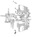
- a metal casting machine 1 is shown, which is intended for the production of metal castings in the die-casting process.
- the metal casting machine 1 has a casting or storage chamber 2, which is provided for storing the molten metal to be processed.
- a multi-part mold 3 is provided which is formed as a permanent mold or as a mold.
- the mold parts 4, 5 of the mold 3 enclose a mold cavity 6, which is intended for pressing and solidification of the molten metal and essentially defines the outer contour of the casting to be produced.
- the casting or storage chamber 2 is designed for pressureless storage of the molten metal.
- the casting or storage chamber 2 is connected to the casting mold 3 via at least one molten metal pumping device 7, which sucks the molten metal from the casting or storage chamber 2 and presses it into the mold cavity 6 of the casting mold 3.
- a molten metal pumping device 7 By the non-pressurized storage of the molten metal in the casting or storage chamber 2 and by the transport of the molten metal by means of a molten metal pumping device 7, an oxygen-poor or oxygen-free protective gas atmosphere can be built up in the casting or storage chamber 2, which covers the molten metal airtight.
- the molten metal pumping device 7 of the metal die-casting machine 1 shown here rather aspirates the molten metal from the casting or storage chamber 2 and pushes the required partial amount of the molten metal into the mold cavity 6 of the casting mold 3.
- the metal die-casting machine 1 shown here only the amount of metal needed for the next casting process and thus only a relatively small volume must be moved, the following work cycles and short cycle times are quickly possible.
- the cyclic-continuous operation of the metal casting machine 1 shown here is further facilitated by the provision of a chamber opening 8 protruding from the outside unhindered and projecting laterally over the metal die-casting machine 1. Since the casting or storage chamber 2 is operated without pressure and since the chamber opening 8 is accessible from the outside unhindered, the refill can be refilled with new metal at any time and without interrupting the production process batchwise or continuously by means of feed system. Once the constancy of the production parameters has been reached, it no longer has to be rebuilt with each new batch as before, but can be continued independently of the metal supply. Quality and efficiency are significantly improved. About the, with the help of a lid 9 closable chamber opening 8, if necessary, additional molten metal can be refilled.
- the molten metal pumping device 7 upstream of a filter device for filtering the molten metal upstream.
- the filter device arranged in the casting or storage chamber 2 has a ceramic protective tube 10 against Groboxide and other coarse impurities which may be present in the molten metal.
- the ceramic protective tube 10 surrounds a ceramic filter tube 11, which is provided for filtering out fine oxides and other finer impurities.
- the molten metal pumping device 7 draws the molten metal via a riser 12 whose inflow-side inlet opening 13 is arranged at a distance below the molten metal level.
- the upstream-side intake port 13 is located at a distance below the molten metal level, suction of the impurities settling on the surface of the molten metal is avoided.
- a partial portion of a pipe section of the riser pipe 12 connected to the molten metal pumping device is surrounded by the outer ceramic protective pipe 10 and the inner ceramic filter pipe 11, the inflow-side and downwardly directed inlet opening 13.
- a gravity valve 14 which is provided for closing the inlet opening.
- This gravity valve has a valve body 15, which is designed here as a tungsten ball.
- a multi-way valve 30 is interposed in the conveying path between the casting or storage chamber 2 and the mold 3 in a first valve position connecting the casting or storage chamber 2 with the molten metal pumping device 7 and in a second valve position the molten metal pumping device 7 and the mold cavity 6 of the casting mold 3.
- This multi-way valve 15 is designed here as a stopper valve, which has a locking slide 16 which acts in the first valve position the an outlet opening 17 of the casting or storage chamber 2 bounding edge area with its free end of the slider tight and the molten metal pumping device 7 and the mold cavity 6 via a groove provided on the slider circumference 20 connects to each other, and in a second valve position the connection between the casting or storage chamber 2 and the molten metal pumping device 7 releases and with its slider circumference the connection between the molten metal pumping device 7 and the casting or storage chamber 2 closes tightly.
- the molten metal pumping device 7, in which the multi-way valve 15 is integrated here, has a pumping chamber 21 into which the molten metal can be sucked by means of a vacuum in order to subsequently supply the subset of the molten metal in the pumping chamber 21 via an overpressure in the Pump chamber 21 to be able to press out of the pumping chamber 21 in the mold cavity 6 of the mold 3.
- the casting mold 3 is designed here in two parts and has a fixed casting mold part 22 and a movable casting mold part 23.
- the fixed and movable mold parts 22, 23 define the mold cavity 6 of the mold 3.
- the fixed mold part 22 has an opening in the mold cavity 6 inlet opening 24, which is associated with a locking slide 25 in the movable mold part 23.
- Gate valve 25 shown in detail is movable by means of a gate valve drive between an open position and a closed position, in which closed position of the gate valve 25 at which the inlet opening 24 bounding peripheral edge region is tight.
- the locking slide 25 has two locking slide parts 26, 27 which are displaceable relative to one another, of which a first, in the closed position on the peripheral edge region of the inlet opening 24 close-fitting gate valve member 26 is slidably guided against a restoring force in the second gate valve member 27.
- the restoring force is designed here as a return spring 28.
- rod-shaped heating elements 31 are arranged distributed, which should hold the molten metal to the mold 3 in the liquid state.
Landscapes
- Engineering & Computer Science (AREA)
- Mechanical Engineering (AREA)
- Molds, Cores, And Manufacturing Methods Thereof (AREA)
- Casting Support Devices, Ladles, And Melt Control Thereby (AREA)
Applications Claiming Priority (1)
| Application Number | Priority Date | Filing Date | Title |
|---|---|---|---|
| DE200910051879 DE102009051879B3 (de) | 2009-11-04 | 2009-11-04 | Metall-Druckgussmaschine |
Publications (2)
| Publication Number | Publication Date |
|---|---|
| EP2319638A2 true EP2319638A2 (fr) | 2011-05-11 |
| EP2319638A3 EP2319638A3 (fr) | 2012-01-18 |
Family
ID=43770498
Family Applications (1)
| Application Number | Title | Priority Date | Filing Date |
|---|---|---|---|
| EP10013976A Withdrawn EP2319638A3 (fr) | 2009-11-04 | 2010-10-26 | Machine de moulage sous pression de métal |
Country Status (2)
| Country | Link |
|---|---|
| EP (1) | EP2319638A3 (fr) |
| DE (1) | DE102009051879B3 (fr) |
Cited By (8)
| Publication number | Priority date | Publication date | Assignee | Title |
|---|---|---|---|---|
| WO2013023754A1 (fr) * | 2011-08-12 | 2013-02-21 | Baumgartner Henrich G | Machine et procédé de coulée sous pression |
| ITUB20152405A1 (it) * | 2015-07-22 | 2017-01-22 | Hydromec S R L | Procedimento per la realizzazione di oggetti in alluminio, leghe di alluminio, leghe leggere, ottone, bronzo e simili |
| WO2017026959A1 (fr) * | 2015-08-10 | 2017-02-16 | Maxion Inci Jant Sanayi Anonim Sirketi | Production de jante de roue coulée par un procédé de pompage |
| EP3170582A1 (fr) | 2015-11-19 | 2017-05-24 | Idra S.R.L. | Procédé et appareil de moulage d'objets en aluminium, alliages d'aluminium, alliages légers, laiton et matières analogues |
| CN106735142A (zh) * | 2016-12-16 | 2017-05-31 | 山东滨州渤海活塞股份有限公司 | 生产铝活塞毛坯的自动铸造机 |
| EP3539694A1 (fr) * | 2018-03-13 | 2019-09-18 | Citic Dicastal Co., Ltd. | Procédé et dispositif de forgeage liquide de roue d'aluminium |
| US20190283120A1 (en) * | 2018-03-13 | 2019-09-19 | Citic Dicastal Co., Ltd | Aluminum alloy low-pressure casting device and process |
| CN112207259A (zh) * | 2020-09-29 | 2021-01-12 | 浙江新峰机械有限公司 | 一种轮毂成型模具 |
Families Citing this family (6)
| Publication number | Priority date | Publication date | Assignee | Title |
|---|---|---|---|---|
| DE102014015557B3 (de) * | 2014-10-21 | 2016-03-03 | Heinrich G. Baumgartner | Vertikal-Gasdruck-Gießmaschine |
| DE102016106256B3 (de) * | 2016-04-06 | 2017-03-02 | Stefan Argirov | Vorrichtung zur Herstellung von Gussteilen, wie Aluminiumguss, im Niederdruckgießverfahren |
| DE102016107572B3 (de) * | 2016-04-22 | 2017-05-18 | Stefan Argirov | Vorrichtung zur Herstellung von Gussteilen, wie Alumiumguss, im Niederdruckgießverfahren |
| PL3330020T3 (pl) | 2016-12-05 | 2022-02-07 | Mubea Performance Wheels Gmbh | Urządzenie odlewnicze i sposób odlewania |
| DE102016123595B4 (de) * | 2016-12-06 | 2018-10-31 | Carsten Speckmann | Gießofen für den Niederdruckguss |
| CN109014157B (zh) * | 2018-08-17 | 2020-07-17 | 云南昆钢重型装备制造集团有限公司 | 一种移动式金属液自动浇铸装置 |
Citations (3)
| Publication number | Priority date | Publication date | Assignee | Title |
|---|---|---|---|---|
| WO2002038313A1 (fr) | 2000-11-09 | 2002-05-16 | Alcoa Inc. | Systeme et procede d'injecteur de metal fondu a filtrage |
| DE102006027171B4 (de) | 2006-06-07 | 2008-02-07 | BAM Bundesanstalt für Materialforschung und -prüfung | Vorrichtung und Verfahren zum Niederdruckheißgießen mit Druckverstärker sowie Druckverstärker |
| EP1894648A1 (fr) | 2006-08-28 | 2008-03-05 | Ing. Rauch Fertigungstechnik GmbH | Procédé de coulée à basse pression et dispositif correspondant |
Family Cites Families (15)
| Publication number | Priority date | Publication date | Assignee | Title |
|---|---|---|---|---|
| GB1152505A (en) * | 1967-06-23 | 1969-05-21 | Dow Chemical Co | Filter Apparatus |
| GB1377628A (en) * | 1971-09-24 | 1974-12-18 | Stamp T B | Apparatus for metering or pouring molten metal such as lead |
| US4474315A (en) * | 1982-04-15 | 1984-10-02 | Kennecott Corporation | Molten metal transfer device |
| IT1231211B (it) * | 1989-08-24 | 1991-11-23 | Tva Holding | Procedimento per la colata a pressione controllata di metalli fusi, particolarmente leghe leggere di alluminio e di magnesio, e apparecchiatura per la sua esecuzione |
| US5407000A (en) * | 1992-02-13 | 1995-04-18 | The Dow Chemical Company | Method and apparatus for handling molten metals |
| DE69833306T2 (de) * | 1997-02-04 | 2006-09-07 | Tounetsu Co., Ltd., Amagasaki | Vorrichtung zum zuführen von metallschmelze in vorgegebenen mengen |
| JP4678978B2 (ja) * | 2001-04-09 | 2011-04-27 | 株式会社アーレスティ | 金属溶湯用給湯装置 |
| US6505674B1 (en) * | 2001-04-19 | 2003-01-14 | Alcoa Inc. | Injector for molten metal supply system |
| ITMI20010949A1 (it) * | 2001-05-09 | 2002-11-09 | Claudio Frulla | Apparecchiatura per la realizzazione di puntali per scarpe di sucurezza e simili in alluminio sue leghe e leghe leggere in genere nonche' pr |
| DE10233962A1 (de) * | 2001-07-27 | 2003-03-13 | Kurtz Gmbh | Aktivspeisungsadapter |
| DE10201983A1 (de) * | 2002-01-21 | 2003-07-31 | Rauch Fertigungstech Gmbh | Giessvorrichtung |
| US6945310B2 (en) * | 2003-05-19 | 2005-09-20 | Takata Corporation | Method and apparatus for manufacturing metallic parts by die casting |
| ITMI20032186A1 (it) * | 2003-11-12 | 2005-05-13 | Claudio Frulla | Apparecchiatuira per lo stampaggio di oggetti in alluminio, |
| JP2005161339A (ja) * | 2003-12-01 | 2005-06-23 | Hiroshima Aluminum Industry Co Ltd | 自動溶湯供給装置 |
| DE202004020881U1 (de) * | 2004-09-06 | 2006-03-16 | Hydro Aluminium Alucast Gmbh | Vorrichtung zum Gießen von Metallschmelze |
-
2009
- 2009-11-04 DE DE200910051879 patent/DE102009051879B3/de not_active Expired - Fee Related
-
2010
- 2010-10-26 EP EP10013976A patent/EP2319638A3/fr not_active Withdrawn
Patent Citations (3)
| Publication number | Priority date | Publication date | Assignee | Title |
|---|---|---|---|---|
| WO2002038313A1 (fr) | 2000-11-09 | 2002-05-16 | Alcoa Inc. | Systeme et procede d'injecteur de metal fondu a filtrage |
| DE102006027171B4 (de) | 2006-06-07 | 2008-02-07 | BAM Bundesanstalt für Materialforschung und -prüfung | Vorrichtung und Verfahren zum Niederdruckheißgießen mit Druckverstärker sowie Druckverstärker |
| EP1894648A1 (fr) | 2006-08-28 | 2008-03-05 | Ing. Rauch Fertigungstechnik GmbH | Procédé de coulée à basse pression et dispositif correspondant |
Cited By (12)
| Publication number | Priority date | Publication date | Assignee | Title |
|---|---|---|---|---|
| WO2013023754A1 (fr) * | 2011-08-12 | 2013-02-21 | Baumgartner Henrich G | Machine et procédé de coulée sous pression |
| CN103747895A (zh) * | 2011-08-12 | 2014-04-23 | 海因里希·G·鲍姆加特纳 | 压铸机以及压铸方法 |
| ITUB20152405A1 (it) * | 2015-07-22 | 2017-01-22 | Hydromec S R L | Procedimento per la realizzazione di oggetti in alluminio, leghe di alluminio, leghe leggere, ottone, bronzo e simili |
| WO2017013590A1 (fr) * | 2015-07-22 | 2017-01-26 | Hydromec S.R.L. | Procédé pour la production d'objets en aluminium, en alliages d'aluminium, en alliages légers, en laiton, en bronze et similaire |
| WO2017026959A1 (fr) * | 2015-08-10 | 2017-02-16 | Maxion Inci Jant Sanayi Anonim Sirketi | Production de jante de roue coulée par un procédé de pompage |
| EP3170582A1 (fr) | 2015-11-19 | 2017-05-24 | Idra S.R.L. | Procédé et appareil de moulage d'objets en aluminium, alliages d'aluminium, alliages légers, laiton et matières analogues |
| CN106735142A (zh) * | 2016-12-16 | 2017-05-31 | 山东滨州渤海活塞股份有限公司 | 生产铝活塞毛坯的自动铸造机 |
| EP3539694A1 (fr) * | 2018-03-13 | 2019-09-18 | Citic Dicastal Co., Ltd. | Procédé et dispositif de forgeage liquide de roue d'aluminium |
| US20190283120A1 (en) * | 2018-03-13 | 2019-09-19 | Citic Dicastal Co., Ltd | Aluminum alloy low-pressure casting device and process |
| US10758973B2 (en) | 2018-03-13 | 2020-09-01 | Citic Dicastal Co., Ltd | Aluminum wheel squeeze casting process and device |
| US10807160B2 (en) * | 2018-03-13 | 2020-10-20 | Citic Dicastal Co., Ltd | Aluminum alloy low-pressure casting device and process |
| CN112207259A (zh) * | 2020-09-29 | 2021-01-12 | 浙江新峰机械有限公司 | 一种轮毂成型模具 |
Also Published As
| Publication number | Publication date |
|---|---|
| DE102009051879B3 (de) | 2011-06-01 |
| EP2319638A3 (fr) | 2012-01-18 |
Similar Documents
| Publication | Publication Date | Title |
|---|---|---|
| DE102009051879B3 (de) | Metall-Druckgussmaschine | |
| DE3518635C2 (de) | Druckgußvorrichtung | |
| DE112013006075B4 (de) | Giessvorrichtung und Giessverfahren | |
| CH654768A5 (de) | Entgasungsvorrichtung an einer druck- oder spritzgiessform. | |
| DE1249464B (de) | Druckgießverfahren und Druckgießmaschine | |
| DE3879285T2 (de) | Hydraulisches kontrollverfahren fuer werkzeuge. | |
| CH700743A1 (de) | Entlüftungseinrichtung für Giessvorrichtungen. | |
| DE4243735C2 (de) | Vorrichtung zum Schließen und Zuhalten der Form einer Formmaschine | |
| DE2419869A1 (de) | Verfahren zum formen von gegenstaenden und vorrichtung zur durchfuehrung des verfahrens | |
| EP3122494B1 (fr) | Dispositif de coulée sous pression d'une pièce métallique | |
| DE10025489C2 (de) | Vorrichtung und Verfahren zur Herstellung von Metall-Keramik-Verbundwerkstoffen | |
| DE102011110176B4 (de) | Druckgießmaschine sowie Druckgießverfahren | |
| EP2588261B1 (fr) | Procédé pour remplir la cavité de moulage d'un dispositif de moulage sous pression, ensemble de soupapes et dispositif de moulage sous pression pour la mise en oeuvre du procédé | |
| DE19605727A1 (de) | Vakuum-Druckgießmaschine | |
| DE2408878C3 (de) | Vorrichtung für den Spritzguß von Formungen aus ungebrannten keramischen Massen | |
| DE3240022A1 (de) | Formmaschine des gashaertenden typs | |
| DE102014015557B3 (de) | Vertikal-Gasdruck-Gießmaschine | |
| EP1284168B1 (fr) | Procédé d'opération d'une machine à couler sous pression en chambre chaude et machine à couler sous pression | |
| DE102020129793A1 (de) | Vorrichtung und Verfahren zum Druckgießen von Metall | |
| EP3511090B1 (fr) | Machine de coulée sous pression à chambre froide | |
| EP3389884B1 (fr) | Presse à filer des barres et des tubes ou presse à filer les métaux | |
| DE102009012636A1 (de) | Gießbehälter für eine Warmkammer-Druckgießmaschine | |
| DE10147158B4 (de) | Verfahren zum Gießen eines Gießteils oder Umgießen eines Bauteils sowie Vorrichtung zur Durchführung des Verfahrens | |
| EP3790689B1 (fr) | Module d'un dispositif de moulage sous pression | |
| DE102004005686A1 (de) | Antriebseinheit insbesondere für Spritzgießmaschinen |
Legal Events
| Date | Code | Title | Description |
|---|---|---|---|
| PUAI | Public reference made under article 153(3) epc to a published international application that has entered the european phase |
Free format text: ORIGINAL CODE: 0009012 |
|
| AK | Designated contracting states |
Kind code of ref document: A2 Designated state(s): AL AT BE BG CH CY CZ DE DK EE ES FI FR GB GR HR HU IE IS IT LI LT LU LV MC MK MT NL NO PL PT RO RS SE SI SK SM TR |
|
| AX | Request for extension of the european patent |
Extension state: BA ME |
|
| RIC1 | Information provided on ipc code assigned before grant |
Ipc: B22D 27/11 20060101ALI20110905BHEP Ipc: B22D 18/04 20060101ALI20110905BHEP Ipc: B22D 18/02 20060101ALI20110905BHEP Ipc: B22D 17/30 20060101ALI20110905BHEP Ipc: B22D 17/06 20060101AFI20110905BHEP |
|
| PUAL | Search report despatched |
Free format text: ORIGINAL CODE: 0009013 |
|
| AK | Designated contracting states |
Kind code of ref document: A3 Designated state(s): AL AT BE BG CH CY CZ DE DK EE ES FI FR GB GR HR HU IE IS IT LI LT LU LV MC MK MT NL NO PL PT RO RS SE SI SK SM TR |
|
| AX | Request for extension of the european patent |
Extension state: BA ME |
|
| RIC1 | Information provided on ipc code assigned before grant |
Ipc: B22D 39/02 20060101ALI20111214BHEP Ipc: B22D 43/00 20060101ALI20111214BHEP Ipc: B22D 27/11 20060101ALI20111214BHEP Ipc: B22D 18/04 20060101ALI20111214BHEP Ipc: B22D 18/02 20060101ALI20111214BHEP Ipc: B22D 17/30 20060101ALI20111214BHEP Ipc: B22D 17/06 20060101AFI20111214BHEP |
|
| 17P | Request for examination filed |
Effective date: 20120706 |
|
| 17Q | First examination report despatched |
Effective date: 20120918 |
|
| STAA | Information on the status of an ep patent application or granted ep patent |
Free format text: STATUS: THE APPLICATION HAS BEEN WITHDRAWN |
|
| 18W | Application withdrawn |
Effective date: 20141031 |