EP2320003A1 - Working method for constructing an accessible insulation for the ceiling of the top floor and an insulation structure constructed according to this method - Google Patents
Working method for constructing an accessible insulation for the ceiling of the top floor and an insulation structure constructed according to this method Download PDFInfo
- Publication number
- EP2320003A1 EP2320003A1 EP09401034A EP09401034A EP2320003A1 EP 2320003 A1 EP2320003 A1 EP 2320003A1 EP 09401034 A EP09401034 A EP 09401034A EP 09401034 A EP09401034 A EP 09401034A EP 2320003 A1 EP2320003 A1 EP 2320003A1
- Authority
- EP
- European Patent Office
- Prior art keywords
- load distribution
- insulation
- ceiling
- plates
- pipe section
- Prior art date
- Legal status (The legal status is an assumption and is not a legal conclusion. Google has not performed a legal analysis and makes no representation as to the accuracy of the status listed.)
- Withdrawn
Links
Images

Classifications
-
- E—FIXED CONSTRUCTIONS
- E04—BUILDING
- E04D—ROOF COVERINGS; SKY-LIGHTS; GUTTERS; ROOF-WORKING TOOLS
- E04D11/00—Roof covering, as far as not restricted to features covered by only one of groups E04D1/00 - E04D9/00; Roof covering in ways not provided for by groups E04D1/00 - E04D9/00, e.g. built-up roofs, elevated load-supporting roof coverings
- E04D11/005—Supports for elevated load-supporting roof coverings
-
- E—FIXED CONSTRUCTIONS
- E04—BUILDING
- E04D—ROOF COVERINGS; SKY-LIGHTS; GUTTERS; ROOF-WORKING TOOLS
- E04D13/00—Special arrangements or devices in connection with roof coverings; Protection against birds; Roof drainage ; Sky-lights
- E04D13/16—Insulating devices or arrangements in so far as the roof covering is concerned, e.g. characterised by the material or composition of the roof insulating material or its integration in the roof structure
- E04D13/1606—Insulation of the roof covering characterised by its integration in the roof structure
- E04D13/1668—Insulation of the roof covering characterised by its integration in the roof structure the insulating material being masses or granules applied in situ
-
- E—FIXED CONSTRUCTIONS
- E04—BUILDING
- E04D—ROOF COVERINGS; SKY-LIGHTS; GUTTERS; ROOF-WORKING TOOLS
- E04D13/00—Special arrangements or devices in connection with roof coverings; Protection against birds; Roof drainage ; Sky-lights
- E04D13/16—Insulating devices or arrangements in so far as the roof covering is concerned, e.g. characterised by the material or composition of the roof insulating material or its integration in the roof structure
- E04D13/1606—Insulation of the roof covering characterised by its integration in the roof structure
- E04D13/1681—Insulating of pre-existing roofs with or without ventilating arrangements
Definitions
- the invention relates to a working method for creating a walkable insulation for the upper floor ceiling in buildings with distributed on the floor slab erected stamps and placed thereon, supporting material plate, wherein the punch is formed from a pipe section, wherein the pipe longitudinal axis of the pipe section is arranged vertically in installation orientation , as well as a created Dämmungsup.
- Such walkable insulation is from the German utility model DE 20 2005 019 245 known to the applicant.
- Such walkable insulation has been used several times in the renovation of older buildings.
- the upper storey ceiling is the worst insulated component. Concrete ceilings are usually executed without insulation. Accordingly, the heat losses in the cold season are very large.
- the attic which is raised to the ceiling, heats up so much that even living rooms underneath it are undesirably warmed up.
- an insulation system was developed by the applicant, which has wood stamp on the new floor as a load-bearing wood-based panel, such as OSB or chipboard is placed.
- the cavity between the original raw ceiling (concrete ceiling) and the wood-based panel clamped by the wooden punches is then blown without joints, for example with a cellulose insulation material.
- This system has been adapted according to DE 20 2005 019 245 optimized that the wood stamp has been replaced by a stamp, the installation orientation in Cross-section to the vertical has a smaller compared to its area coverage cross-sectional area. It has also been proposed to use a pipe section, for example made of cardboard or plastic as a stamp. However, the construction of such walkable insulation was relatively expensive and sometimes led to undesirable shifts of the arranged under the load-bearing material plate pipe sections, so that a safe load bearing in parts of already laid surfaces could not be guaranteed.
- the pipe sections in particular cardboard tube sections before laying the walkable insulation already filled with the cellulose fluff provided for insulation are manageable, without the need for a separate fixation of the captured therein in the cylindrical interior flakes. Solely, it is necessary to press the cellulose flakes tightly pressed into the interior of the pipe section. It is thus possible to cut the pipe sections to the desired length, for example in a prefabrication stage, and to automatically fill them with the cellulose flakes. For this purpose, a separate cellulose flake filling and pressing device can also be used. The prepared filled with cellulose flakes pipe sections can then be transported to the site and placed there according to the next step. The installation is carried out in a predetermined grid that results from the size of the aufGHzden bearing material plates, for example, the grid can be 62.5 cm.
- the load distribution elements are small plate sections, for example square 15 x 15 cm, circular or preferably flat elongated as a board.
- the load distribution element is formed for example of natural wood, wood material or rigid sandwich material.
- the load distribution element has a high strength.
- it is suitable to receive fastening means, such as screws or nails frictionally.
- the load distribution element is designed as a flat elongated board and rests on at least two spaced-apart punches, which are on the board butt joints of the deposited thereon material plates.
- the boards provided as a load distribution element are placed on the stamp distributed in the grid on the blanket stamp that the Stirnspirefugen the adjoining in a series of material plates are each arranged centrally on a board. This ensures that the entire butt joint is supported by the board, so that unwanted overstressing and destruction of the tongue and groove joint on the frontal impact of the adjacent material plates can be avoided.
- the row is then shifted at least one pitch, so that no four bumps cross each other at one point.
- a high strength is realized at the abutting on their longitudinal sides of the material plates by the offset of the rows.
- the material plates In order to prevent the material plates from slipping apart, they are connected to one another in the region of the bearing on the load distribution element by nails or screws via the load distribution element. Characterized in that the fastening means (screw / nail) passes through the material plate and the load distribution element and preferably 2 to 3 cm in the Interior of the pipe section arranged underneath, is also reliably avoided that the pipe section could slip and migrate at a possibly slightly hollow surface produced from the material plates.
- both the dumping of cellulose flakes in the cavity between the built-up material plates and upper floor ceiling which should be done train by train when laying the material plates, or by blowing the cellulose flakes with known injection devices on appropriately provided or subsequently drilled filling openings.
- Fig. 1 the basic structure of a walk-in insulation is shown in a cut-out cross-section.
- a floor ceiling G which is for example a concrete ceiling
- stamp 1 spaced from one another stamp 1 are placed.
- the stamp 1 consists of a pipe section made of cardboard, which is filled with cellulose flakes 3 as an insulating material in its interior I filled.
- a load distribution element 22 on the as new walkable floor structure 2 suitable material plates 21, for example, wood-based panels (OSB or chipboard) are placed. Preference is given to material plates which have a tongue and groove connection or a two-layer overlapping division for load-bearing and support also on plate edges.
- the stamp 1 are preferably arranged in a fraction of the laying of the material plates to each other objected.
- Dry screed plates with a dimension of 59 cm x 244 cm
- the stamp 1 are placed, for example, at a distance of 59 cm to each other in parallel rows, each row is constructed with a distance of 61 cm.
- the dry screed plates can be placed on the provided with load distribution elements, erected stamp 1 that the edges and in particular the four corners of the dry screed plate are supported directly by punches 1.
- the plates are stored by at least one grid dimension of 61 cm, so that again the edges and the four corners of the dry screed plate rest on punches 1, but four plates never meet at one point.
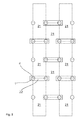
- Fig. 2 shown schematically.
- the arranged under the plates 21 stamp 1 are shown for better orientation of their position by a circle.
- the positions of the nails 4 are represented by dots, as will be described later.
- Fig. 2 is the frontal butt joint of the juxtaposed in a row with tongue and groove material panels shown in phantom. These end-side joints lie respectively on the board-shaped load distribution elements 22 and are thus supported on both sides of the joint by the load distribution element 22. A breakout of the tongue and groove joint on this front side Joint is thus excluded.
- the load distribution element 22 is, for example, a wooden board in a thickness of 3 to 4 cm and thus serves as a front bump pad.
- fastening means 4 here nails
- at least one nail in the region of the load distribution element 22 per material plate 21 is nailed to the corner of the plate so that its downwardly projecting from the load distribution element 22 tip 41 of the nail 4 in the interior I, which is spanned by the pipe section 1, protrudes.
- cavity H is now poured either when laying the material plates 21 train by train insulation material manually or blown in a suitable manner after installation.
- the cavity H is thus completely filled with insulating material 3, for example cellulose flakes.
Landscapes
- Engineering & Computer Science (AREA)
- Architecture (AREA)
- Civil Engineering (AREA)
- Structural Engineering (AREA)
- Floor Finish (AREA)
Abstract
Description
Die Erfindung betrifft ein Arbeitsverfahren zum Erstellen einer begehbaren Dämmung für die obere Geschossdecke in Gebäuden mit auf der Geschossdecke verteilt aufgestellten Stempeln und einer darauf gelegten, tragenden Werkstoffplatte, wobei der Stempel aus einem Rohrabschnitt gebildet ist, wobei die Rohrlängsachse des Rohrabschnitts in Einbauorientierung vertikal angeordnet ist, sowie einen damit erstellten Dämmungsaufbau.The invention relates to a working method for creating a walkable insulation for the upper floor ceiling in buildings with distributed on the floor slab erected stamps and placed thereon, supporting material plate, wherein the punch is formed from a pipe section, wherein the pipe longitudinal axis of the pipe section is arranged vertically in installation orientation , as well as a created Dämmungsaufbau.
Eine derartige begehbare Dämmung ist aus dem deutschen Gebrauchsmuster
Dafür wurde von der Anmelderin ein Dämmsystem entwickelt, das Holzstempel aufweist, auf die als neuer Fußboden eine tragende Holzwerkstoffplatte, beispielsweise OSB- oder Spanplatte aufgelegt wird. Der von den Holzstempeln aufgespannte Hohlraum zwischen ursprünglicher Rohdecke (Betondecke) und der Holzwerkstoffplatte wird dann beispielsweise mit einem Zellulosedämmstoff fugenfrei ausgeblasen.For this purpose, an insulation system was developed by the applicant, which has wood stamp on the new floor as a load-bearing wood-based panel, such as OSB or chipboard is placed. The cavity between the original raw ceiling (concrete ceiling) and the wood-based panel clamped by the wooden punches is then blown without joints, for example with a cellulose insulation material.
Dieses System wurde dahingehend gemäß
Daher ist es Aufgabe der Erfindung, ein Arbeitsverfahren zum Erstellen einer begehbaren Dämmung anzugeben, das eine schnelle und damit wirtschaftliche Verlegung und eine sichere Fixierung der als Stempel dienenden Rohrabschnitte ermöglicht. Ferner ist es Aufgabe der Erfindung, einen Dämmungsaufbau anzugeben, der eine hohe Stabilität aufweist.Therefore, it is an object of the invention to provide a working method for creating a walkable insulation, which allows a fast and thus economical installation and secure fixing of serving as a stamp pipe sections. It is another object of the invention to provide a Dämmungsaufbau having a high stability.
Gelöst wird diese Aufgabe nach einem Arbeitsverfahren gemäß Anspruch 1 sowie einem Dämmungsaufbau nach Anspruch 4.This object is achieved by a method according to
Überraschenderweise hat sich gezeigt, dass die Rohrabschnitte, insbesondere Papperohrabschnitte vor der Verlegung der begehbaren Dämmung bereits mit dem zur Dämmung vorgesehenen Zelluloseflocken befüllt handhabbar sind, ohne dass es einer gesonderten Fixierung der darin im zylindrischen Innenraum aufgenommenen Flocken bedarf. Einzig und allein ist es erforderlich, die Zelluloseflocken fest zusammengepresst in den Innenraum des Rohrabschnittes zu pressen. Es ist somit möglich, die Rohrabschnitte beispielsweise in einer Vorfertigungsstufe auf die gewünschte Länge zu schneiden, und automatisiert mit den Zelluloseflocken zu befüllen. Dazu kann auch eine gesonderte Zelluloseflockenfüll- und -pressvorrichtung verwendet werden. Die vorbereiteten mit Zelluloseflocken befüllten Rohrabschnitte können dann zur Baustelle transportiert werden und dort entsprechend des nächsten Arbeitsschrittes aufgestellt werden. Die Aufstellung erfolgt in einem vorbestimmten Rastermaß, dass sich aus der Größe der aufzulegenden tragenden Werkstoffplatten ergibt, beispielsweise kann das Rastermaß 62,5 cm betragen.Surprisingly, it has been shown that the pipe sections, in particular cardboard tube sections before laying the walkable insulation already filled with the cellulose fluff provided for insulation are manageable, without the need for a separate fixation of the captured therein in the cylindrical interior flakes. Solely, it is necessary to press the cellulose flakes tightly pressed into the interior of the pipe section. It is thus possible to cut the pipe sections to the desired length, for example in a prefabrication stage, and to automatically fill them with the cellulose flakes. For this purpose, a separate cellulose flake filling and pressing device can also be used. The prepared filled with cellulose flakes pipe sections can then be transported to the site and placed there according to the next step. The installation is carried out in a predetermined grid that results from the size of the aufzulegenden bearing material plates, for example, the grid can be 62.5 cm.
Die Lastverteilungselemente sind kleine Plattenabschnitte, beispielsweise quadratisch 15 x 15 cm, kreisrund oder bevorzugt flächig langgestreckt als Brett. Das Lastverteilungselement ist beispielsweise aus Naturholz, Holzwerkstoff oder biegesteifem Sandwichwerkstoff gebildet. Damit weist das Lastverteilungselement eine hohe Festigkeit auf. Ferner ist es geeignet, Befestigungsmittel, wie Schrauben oder Nägel kraftschlüssig aufzunehmen. Beim Auflegen der tragenden Werkstoffplatten wird darauf geachtet, dass an aneinanderstoßenden Ecken von zwei stirnseitig aneinanderstoßenden Platten auf jeden Fall ein Lastverteilungselement mit darunter angeordnetem Rohrabschnitt als Stempel angeordnet sind. Bevorzugt ist das Lastverteilungselement als flächig langgestrecktes Brett ausgebildet und liegt auf wenigstens zwei beabstandet zueinander angeordneten Stempeln auf, wobei sich auf dem Brett Stoßfugen der darauf abgelegten Werkstoffplatten befinden. Insbesondere wird bei den bekannten zu verlegenden Werkstoffplatten die als Lastverteilungselement vorgesehenen Bretter so auf die im Rastermaß auf der Rohdecke verteilten Stempel aufgelegt, dass die Stirnstoßfugen der in einer Reihe aneinandergrenzenden Werkstoffplatten jeweils mittig auf einem Brett angeordnet sind. Damit ist gewährleistet, dass die gesamte Stoßfuge von dem Brett unterstütz wird, so dass unerwünschte Überbeanspruchungen und Zerstörungen der Nut-/Federverbindung an dem stirnseitigen Stoß der aneinanderliegenden Werkstoffplatten vermieden werden können. Bei der nächsten Reihe von Werkstoffplatten, die verlegt werden, wird die Reihe dann mindestens um ein Rastermaß verschoben, so dass sich keine vier Stöße an einem Punkt kreuzweise treffen. Somit ist auch eine hohe Festigkeit an den an ihren Längsseiten aneinanderstoßenden Werkstoffplatten durch den Versatz der Reihen realisiert.The load distribution elements are small plate sections, for example square 15 x 15 cm, circular or preferably flat elongated as a board. The load distribution element is formed for example of natural wood, wood material or rigid sandwich material. Thus, the load distribution element has a high strength. Furthermore, it is suitable to receive fastening means, such as screws or nails frictionally. When placing the load-bearing material plates is taken to ensure that at abutting corners of two frontally abutting plates in any case a load distribution element arranged underneath pipe section are arranged as a stamp. Preferably, the load distribution element is designed as a flat elongated board and rests on at least two spaced-apart punches, which are on the board butt joints of the deposited thereon material plates. In particular, in the known material plates to be laid, the boards provided as a load distribution element are placed on the stamp distributed in the grid on the blanket stamp that the Stirnstoßfugen the adjoining in a series of material plates are each arranged centrally on a board. This ensures that the entire butt joint is supported by the board, so that unwanted overstressing and destruction of the tongue and groove joint on the frontal impact of the adjacent material plates can be avoided. For the next set of slabs of material being laid, the row is then shifted at least one pitch, so that no four bumps cross each other at one point. Thus, a high strength is realized at the abutting on their longitudinal sides of the material plates by the offset of the rows.
Um ein Auseinanderrutschen der Werkstoffplatten zu verhindern, werden diese im Bereich der Auflagerung auf dem Lastverteilungselement durch Nägel oder Schrauben über das Lastverteilungselement untereinander verbunden. Dadurch, dass das Befestigungsmittel (Schraube/Nagel) durch die Werkstoffplatte und das Lastverteilungselement hindurchgreift und bevorzugt 2 bis 3 cm in den Innenraum des darunter angeordneten Rohrabschnitts reicht, wird auch sicher vermieden, dass der Rohrabschnitt bei einer etwaig leicht hohl liegenden aus den Werkstoffplatten erzeugten Fläche verrutschen und abwandern könnte.In order to prevent the material plates from slipping apart, they are connected to one another in the region of the bearing on the load distribution element by nails or screws via the load distribution element. Characterized in that the fastening means (screw / nail) passes through the material plate and the load distribution element and preferably 2 to 3 cm in the Interior of the pipe section arranged underneath, is also reliably avoided that the pipe section could slip and migrate at a possibly slightly hollow surface produced from the material plates.
Diese Gefahr besteht insbesondere beim Verfüllen des zwischen den tragenden Werkstoffplatten und der oberen Geschossdecke aufgebauten Hohlraums mit Zelluloseflocken, da diese möglicherweise die Rohrabschnitte vor sich hertreiben könnten, insbesondere beim Verfüllen durch Einblasen.In particular, this risk exists when filling the cellulosic fluff cavity formed between the load-bearing material panels and the upper floor slab, as these could possibly drive the pipe sections in front of them, in particular during filling by blowing.
Als Verfüllungsmethoden eignet sich sowohl das Einschütten von Zelluloseflocken in den Hohlraum zwischen aufgebauten Werkstoffplatten und oberer Geschossdecke, was dann allerdings Zug um Zug beim Verlegen der Werkstoffplatten erfolgen sollte, oder durch Einblasen der Zelluloseflocken mit bekannten Einblasvorrichtungen über entsprechend vorgesehene oder nachträglich eingebohrte Füllöffnungen.As filling methods, both the dumping of cellulose flakes in the cavity between the built-up material plates and upper floor ceiling, which should be done train by train when laying the material plates, or by blowing the cellulose flakes with known injection devices on appropriately provided or subsequently drilled filling openings.
Nachfolgend wird ein Ausführungsbeispiel der Erfindung anhand der beiliegenden Zeichnungen detailliert beschrieben.Hereinafter, an embodiment of the invention will be described in detail with reference to the accompanying drawings.
- Fig. 1Fig. 1
- eine begehbare Dämmung mit einem rohrförmigen Stempel im Querschnitt unda walkable insulation with a tubular stamp in cross section and
- Fig. 2Fig. 2
- eine schematische Draufsicht einer aus den Werkstoffplatten gebildeten Fläche.a schematic plan view of a surface formed from the material plates.
In
Die Stempel 1 sind dabei bevorzugt in einem Bruchteil des Verlegemaßes der Werkstoffplatten zueinander beanstandet angeordnet. Bei bekannten sog. Trockenestrichplatten mit einem Maß von 59 cm x 244 cm werden die Stempel 1 beispielsweise in einem Abstand von 59 cm zueinander in parallelen Reihen aufgestellt, wobei jede Reihe mit einem Abstandsmaß von 61 cm aufgebaut ist. Entlang dieser Reihen können die Trockenestrichplatten so auf die mit Lastverteilungselementen versehenen, aufgestellten Stempel 1 aufgelegt werden, dass die Kanten und insbesondere die vier Ecken der Trockenestrichplatte unmittelbar von Stempeln 1 gestützt werden. In der nächsten Verlegereihe in Längsrichtung sind die Platten um wengistens ein Rastermaß von 61 cm verschoben abgelegt, so dass wiederum die Kanten und die vier Ecken der Trockenestrichplatte auf Stempeln 1 aufliegen, jedoch vier Platten nie an einem Punkt zusammentreffen.The
Besonders bevorzugt ist die Ausbildung der Lastverteilungselemente in Form von flächig langgestreckten Brettern 22, die auf zwei im Rasterabstand beabstandeten Stempeln 1 aufliegen. Ein derartiger Aufbau ist in
In
Nach dem Verlegen der Platten 21 und vor dem Einblasen bzw. Einschütten des Dämmstoffes in den allgemeinen Hohlraum zwischen dem Bodenaufbau 2 und der Geschossdecke G werden die aneinanderstoßenden Platten im Bereich des Stempels 1 durch Befestigungsmittel 4, hier Nägel, befestigt. Dabei wird mindestens je ein Nagel im Bereich des Lastverteilungselementes 22 je Werkstoffplatte 21 so an der Ecke der Platte eingenagelt, dass seine nach unten aus dem Lastverteilungselement 22 hervorstehende Spitze 41 des Nagels 4 in den Innenraum I, der vom Rohrabschnitt 1 aufgespannt wird, hineinragt.After laying the
In den sich zwischen Geschossdecke G und neuem Bodenaufbau 2 bildenden Hohlraum H wird nun entweder beim Verlegen der Werkstoffplatten 21 Zug um Zug Dämmmaterial manuell eingeschüttet oder in geeigneter Weise nach der Verlegung eingeblasen. Der Hohlraum H ist also vollständig mit Dämmstoff 3, beispielsweise Zelluloseflocken ausgefüllt.In which between the floor slab G and
- 11
- Stempel, RohrabschnittStamp, pipe section
- 22
- Bodenaufbaufloor structure
- 2121
- WerkstoffplattenBased panels
- 2222
- Lastverteilungselement, BrettLoad distribution element, board
- 33
- Zelluloseflockencellulose flakes
- 44
- Befestigungsmittel, NagelFastener, nail
- 4141
- Spitzetop
- GG
- Geschossdeckefloor ceiling
- HH
- Hohlraumcavity
- II
- Innenrauminner space
Claims (6)
Priority Applications (1)
| Application Number | Priority Date | Filing Date | Title |
|---|---|---|---|
| EP09401034A EP2320003A1 (en) | 2009-11-05 | 2009-11-05 | Working method for constructing an accessible insulation for the ceiling of the top floor and an insulation structure constructed according to this method |
Applications Claiming Priority (1)
| Application Number | Priority Date | Filing Date | Title |
|---|---|---|---|
| EP09401034A EP2320003A1 (en) | 2009-11-05 | 2009-11-05 | Working method for constructing an accessible insulation for the ceiling of the top floor and an insulation structure constructed according to this method |
Publications (1)
| Publication Number | Publication Date |
|---|---|
| EP2320003A1 true EP2320003A1 (en) | 2011-05-11 |
Family
ID=42144812
Family Applications (1)
| Application Number | Title | Priority Date | Filing Date |
|---|---|---|---|
| EP09401034A Withdrawn EP2320003A1 (en) | 2009-11-05 | 2009-11-05 | Working method for constructing an accessible insulation for the ceiling of the top floor and an insulation structure constructed according to this method |
Country Status (1)
| Country | Link |
|---|---|
| EP (1) | EP2320003A1 (en) |
Citations (6)
| Publication number | Priority date | Publication date | Assignee | Title |
|---|---|---|---|---|
| DE804257C (en) * | 1949-01-01 | 1951-04-19 | Rudolf Boehme | Bracing and reinforcement of formwork, especially for solid ceilings |
| DE2503262A1 (en) * | 1975-01-28 | 1976-07-29 | Gerhard Wischnewski | Industrial double floor slab supports - comprises plastic beaker shaped cups filled with concrete having plastic additive |
| AT369083B (en) * | 1980-08-08 | 1982-12-10 | Mayreder Kraus & Co Ing | FLAT ROOF |
| DE29615537U1 (en) * | 1996-09-06 | 1996-10-24 | Höper, Johannes, 31234 Edemissen | Formwork for level concrete slabs |
| DE19519193A1 (en) * | 1995-05-24 | 1996-11-28 | Hamberger Industriewerke Gmbh | Coupling pre-assembled double swivel supports to plank layer |
| DE202005019245U1 (en) * | 2005-12-09 | 2006-02-02 | Poesis Gmbh | Insulation for an upper story ceiling, for renovation of multi-story buildings to prevent heat loss through the roof, has distributed props for a board to give a walking surface with insulation material filling the spaces |
-
2009
- 2009-11-05 EP EP09401034A patent/EP2320003A1/en not_active Withdrawn
Patent Citations (6)
| Publication number | Priority date | Publication date | Assignee | Title |
|---|---|---|---|---|
| DE804257C (en) * | 1949-01-01 | 1951-04-19 | Rudolf Boehme | Bracing and reinforcement of formwork, especially for solid ceilings |
| DE2503262A1 (en) * | 1975-01-28 | 1976-07-29 | Gerhard Wischnewski | Industrial double floor slab supports - comprises plastic beaker shaped cups filled with concrete having plastic additive |
| AT369083B (en) * | 1980-08-08 | 1982-12-10 | Mayreder Kraus & Co Ing | FLAT ROOF |
| DE19519193A1 (en) * | 1995-05-24 | 1996-11-28 | Hamberger Industriewerke Gmbh | Coupling pre-assembled double swivel supports to plank layer |
| DE29615537U1 (en) * | 1996-09-06 | 1996-10-24 | Höper, Johannes, 31234 Edemissen | Formwork for level concrete slabs |
| DE202005019245U1 (en) * | 2005-12-09 | 2006-02-02 | Poesis Gmbh | Insulation for an upper story ceiling, for renovation of multi-story buildings to prevent heat loss through the roof, has distributed props for a board to give a walking surface with insulation material filling the spaces |
Similar Documents
| Publication | Publication Date | Title |
|---|---|---|
| EP1789640A1 (en) | Construction module | |
| DE102008003281A1 (en) | Surface element for use in production of building board utilized as e.g. cover, has connection running along area of base surface and consisting of tooth system, finger tooth or dovetail connection | |
| EP1497506A1 (en) | Building made of wall hollow heated elements | |
| DE102019112303A1 (en) | Room module, building made from room modules, as well as a manufacturing process for each | |
| EP3067484A1 (en) | Wooden panel for a wood-cement composite structure, wood-cement composite structure and method for its preparation | |
| EP3137700B1 (en) | Method for producing a ceiling in a building | |
| EP2080845B1 (en) | Prefabricated wood element | |
| EP2253890A2 (en) | Structure of panel heating, in particular of underfloor heating for a building | |
| EP2256262B1 (en) | Wood structure module, method for its manufacture and application | |
| EP3926117B1 (en) | Thermal insulation composite system, facade with the thermal insulation composite systemand method for erecting the same | |
| EP2626479A2 (en) | Construction element for installation in expansion joints of buildings | |
| DE1509644A1 (en) | Sound and heat insulating leveling layer for laying dry screed | |
| EP3577286B1 (en) | Construction system | |
| EP1664452A1 (en) | Wall element | |
| AT369083B (en) | FLAT ROOF | |
| EP1323876A1 (en) | Panel, spacer and trusslike beam therefor, building and method of construction | |
| EP1082503B1 (en) | False floor construction | |
| DE102004003366B4 (en) | Method for producing a single-family or multi-family house, precast concrete trough plate for a building ceiling and prefabricated house | |
| DE102006003800C5 (en) | Support element for a roof construction in lightweight metal construction | |
| DE19709661A1 (en) | Flat wooden building component, for walls, floors, etc. | |
| DE19739402C2 (en) | Building corner for a house made of wood | |
| DE102004014765A1 (en) | Industrially prefabricated floor plate has thin flat concrete slab resting on thick wooden beams running longitudinally and has fastening systems along long edges to fasten adjacent beams together | |
| EP1662059A1 (en) | Floor panel for a hollow flooring system, method of production of such a floor panel and hollow flooring system comprising such a floor panel | |
| DE102017114619A1 (en) | Prefabricated wall element | |
| EP2479358B1 (en) | Method for producing a pre-fabricated floor |
Legal Events
| Date | Code | Title | Description |
|---|---|---|---|
| PUAI | Public reference made under article 153(3) epc to a published international application that has entered the european phase |
Free format text: ORIGINAL CODE: 0009012 |
|
| AK | Designated contracting states |
Kind code of ref document: A1 Designated state(s): AT BE BG CH CY CZ DE DK EE ES FI FR GB GR HR HU IE IS IT LI LT LU LV MC MK MT NL NO PL PT RO SE SI SK SM TR |
|
| AX | Request for extension of the european patent |
Extension state: AL BA RS |
|
| 17P | Request for examination filed |
Effective date: 20110929 |
|
| STAA | Information on the status of an ep patent application or granted ep patent |
Free format text: STATUS: THE APPLICATION IS DEEMED TO BE WITHDRAWN |
|
| 18D | Application deemed to be withdrawn |
Effective date: 20130601 |