EP2320003A1 - Procédé de travail pour réaliserr une isolation accessible pour le plafond d'étage supérieur ainsi qu'une structure d'isolation réalisée à l'aide de celle-ci - Google Patents
Procédé de travail pour réaliserr une isolation accessible pour le plafond d'étage supérieur ainsi qu'une structure d'isolation réalisée à l'aide de celle-ci Download PDFInfo
- Publication number
- EP2320003A1 EP2320003A1 EP09401034A EP09401034A EP2320003A1 EP 2320003 A1 EP2320003 A1 EP 2320003A1 EP 09401034 A EP09401034 A EP 09401034A EP 09401034 A EP09401034 A EP 09401034A EP 2320003 A1 EP2320003 A1 EP 2320003A1
- Authority
- EP
- European Patent Office
- Prior art keywords
- load distribution
- insulation
- ceiling
- plates
- pipe section
- Prior art date
- Legal status (The legal status is an assumption and is not a legal conclusion. Google has not performed a legal analysis and makes no representation as to the accuracy of the status listed.)
- Withdrawn
Links
Images

Classifications
-
- E—FIXED CONSTRUCTIONS
- E04—BUILDING
- E04D—ROOF COVERINGS; SKY-LIGHTS; GUTTERS; ROOF-WORKING TOOLS
- E04D11/00—Roof covering, as far as not restricted to features covered by only one of groups E04D1/00 - E04D9/00; Roof covering in ways not provided for by groups E04D1/00 - E04D9/00, e.g. built-up roofs, elevated load-supporting roof coverings
- E04D11/005—Supports for elevated load-supporting roof coverings
-
- E—FIXED CONSTRUCTIONS
- E04—BUILDING
- E04D—ROOF COVERINGS; SKY-LIGHTS; GUTTERS; ROOF-WORKING TOOLS
- E04D13/00—Special arrangements or devices in connection with roof coverings; Protection against birds; Roof drainage ; Sky-lights
- E04D13/16—Insulating devices or arrangements in so far as the roof covering is concerned, e.g. characterised by the material or composition of the roof insulating material or its integration in the roof structure
- E04D13/1606—Insulation of the roof covering characterised by its integration in the roof structure
- E04D13/1668—Insulation of the roof covering characterised by its integration in the roof structure the insulating material being masses or granules applied in situ
-
- E—FIXED CONSTRUCTIONS
- E04—BUILDING
- E04D—ROOF COVERINGS; SKY-LIGHTS; GUTTERS; ROOF-WORKING TOOLS
- E04D13/00—Special arrangements or devices in connection with roof coverings; Protection against birds; Roof drainage ; Sky-lights
- E04D13/16—Insulating devices or arrangements in so far as the roof covering is concerned, e.g. characterised by the material or composition of the roof insulating material or its integration in the roof structure
- E04D13/1606—Insulation of the roof covering characterised by its integration in the roof structure
- E04D13/1681—Insulating of pre-existing roofs with or without ventilating arrangements
Definitions
- the invention relates to a working method for creating a walkable insulation for the upper floor ceiling in buildings with distributed on the floor slab erected stamps and placed thereon, supporting material plate, wherein the punch is formed from a pipe section, wherein the pipe longitudinal axis of the pipe section is arranged vertically in installation orientation , as well as a created Dämmungsup.
- Such walkable insulation is from the German utility model DE 20 2005 019 245 known to the applicant.
- Such walkable insulation has been used several times in the renovation of older buildings.
- the upper storey ceiling is the worst insulated component. Concrete ceilings are usually executed without insulation. Accordingly, the heat losses in the cold season are very large.
- the attic which is raised to the ceiling, heats up so much that even living rooms underneath it are undesirably warmed up.
- an insulation system was developed by the applicant, which has wood stamp on the new floor as a load-bearing wood-based panel, such as OSB or chipboard is placed.
- the cavity between the original raw ceiling (concrete ceiling) and the wood-based panel clamped by the wooden punches is then blown without joints, for example with a cellulose insulation material.
- This system has been adapted according to DE 20 2005 019 245 optimized that the wood stamp has been replaced by a stamp, the installation orientation in Cross-section to the vertical has a smaller compared to its area coverage cross-sectional area. It has also been proposed to use a pipe section, for example made of cardboard or plastic as a stamp. However, the construction of such walkable insulation was relatively expensive and sometimes led to undesirable shifts of the arranged under the load-bearing material plate pipe sections, so that a safe load bearing in parts of already laid surfaces could not be guaranteed.
- the pipe sections in particular cardboard tube sections before laying the walkable insulation already filled with the cellulose fluff provided for insulation are manageable, without the need for a separate fixation of the captured therein in the cylindrical interior flakes. Solely, it is necessary to press the cellulose flakes tightly pressed into the interior of the pipe section. It is thus possible to cut the pipe sections to the desired length, for example in a prefabrication stage, and to automatically fill them with the cellulose flakes. For this purpose, a separate cellulose flake filling and pressing device can also be used. The prepared filled with cellulose flakes pipe sections can then be transported to the site and placed there according to the next step. The installation is carried out in a predetermined grid that results from the size of the aufGHzden bearing material plates, for example, the grid can be 62.5 cm.
- the load distribution elements are small plate sections, for example square 15 x 15 cm, circular or preferably flat elongated as a board.
- the load distribution element is formed for example of natural wood, wood material or rigid sandwich material.
- the load distribution element has a high strength.
- it is suitable to receive fastening means, such as screws or nails frictionally.
- the load distribution element is designed as a flat elongated board and rests on at least two spaced-apart punches, which are on the board butt joints of the deposited thereon material plates.
- the boards provided as a load distribution element are placed on the stamp distributed in the grid on the blanket stamp that the Stirnspirefugen the adjoining in a series of material plates are each arranged centrally on a board. This ensures that the entire butt joint is supported by the board, so that unwanted overstressing and destruction of the tongue and groove joint on the frontal impact of the adjacent material plates can be avoided.
- the row is then shifted at least one pitch, so that no four bumps cross each other at one point.
- a high strength is realized at the abutting on their longitudinal sides of the material plates by the offset of the rows.
- the material plates In order to prevent the material plates from slipping apart, they are connected to one another in the region of the bearing on the load distribution element by nails or screws via the load distribution element. Characterized in that the fastening means (screw / nail) passes through the material plate and the load distribution element and preferably 2 to 3 cm in the Interior of the pipe section arranged underneath, is also reliably avoided that the pipe section could slip and migrate at a possibly slightly hollow surface produced from the material plates.
- both the dumping of cellulose flakes in the cavity between the built-up material plates and upper floor ceiling which should be done train by train when laying the material plates, or by blowing the cellulose flakes with known injection devices on appropriately provided or subsequently drilled filling openings.
- Fig. 1 the basic structure of a walk-in insulation is shown in a cut-out cross-section.
- a floor ceiling G which is for example a concrete ceiling
- stamp 1 spaced from one another stamp 1 are placed.
- the stamp 1 consists of a pipe section made of cardboard, which is filled with cellulose flakes 3 as an insulating material in its interior I filled.
- a load distribution element 22 on the as new walkable floor structure 2 suitable material plates 21, for example, wood-based panels (OSB or chipboard) are placed. Preference is given to material plates which have a tongue and groove connection or a two-layer overlapping division for load-bearing and support also on plate edges.
- the stamp 1 are preferably arranged in a fraction of the laying of the material plates to each other objected.
- Dry screed plates with a dimension of 59 cm x 244 cm
- the stamp 1 are placed, for example, at a distance of 59 cm to each other in parallel rows, each row is constructed with a distance of 61 cm.
- the dry screed plates can be placed on the provided with load distribution elements, erected stamp 1 that the edges and in particular the four corners of the dry screed plate are supported directly by punches 1.
- the plates are stored by at least one grid dimension of 61 cm, so that again the edges and the four corners of the dry screed plate rest on punches 1, but four plates never meet at one point.
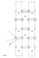
- Fig. 2 shown schematically.
- the arranged under the plates 21 stamp 1 are shown for better orientation of their position by a circle.
- the positions of the nails 4 are represented by dots, as will be described later.
- Fig. 2 is the frontal butt joint of the juxtaposed in a row with tongue and groove material panels shown in phantom. These end-side joints lie respectively on the board-shaped load distribution elements 22 and are thus supported on both sides of the joint by the load distribution element 22. A breakout of the tongue and groove joint on this front side Joint is thus excluded.
- the load distribution element 22 is, for example, a wooden board in a thickness of 3 to 4 cm and thus serves as a front bump pad.
- fastening means 4 here nails
- at least one nail in the region of the load distribution element 22 per material plate 21 is nailed to the corner of the plate so that its downwardly projecting from the load distribution element 22 tip 41 of the nail 4 in the interior I, which is spanned by the pipe section 1, protrudes.
- cavity H is now poured either when laying the material plates 21 train by train insulation material manually or blown in a suitable manner after installation.
- the cavity H is thus completely filled with insulating material 3, for example cellulose flakes.
Landscapes
- Engineering & Computer Science (AREA)
- Architecture (AREA)
- Civil Engineering (AREA)
- Structural Engineering (AREA)
- Floor Finish (AREA)
Priority Applications (1)
| Application Number | Priority Date | Filing Date | Title |
|---|---|---|---|
| EP09401034A EP2320003A1 (fr) | 2009-11-05 | 2009-11-05 | Procédé de travail pour réaliserr une isolation accessible pour le plafond d'étage supérieur ainsi qu'une structure d'isolation réalisée à l'aide de celle-ci |
Applications Claiming Priority (1)
| Application Number | Priority Date | Filing Date | Title |
|---|---|---|---|
| EP09401034A EP2320003A1 (fr) | 2009-11-05 | 2009-11-05 | Procédé de travail pour réaliserr une isolation accessible pour le plafond d'étage supérieur ainsi qu'une structure d'isolation réalisée à l'aide de celle-ci |
Publications (1)
| Publication Number | Publication Date |
|---|---|
| EP2320003A1 true EP2320003A1 (fr) | 2011-05-11 |
Family
ID=42144812
Family Applications (1)
| Application Number | Title | Priority Date | Filing Date |
|---|---|---|---|
| EP09401034A Withdrawn EP2320003A1 (fr) | 2009-11-05 | 2009-11-05 | Procédé de travail pour réaliserr une isolation accessible pour le plafond d'étage supérieur ainsi qu'une structure d'isolation réalisée à l'aide de celle-ci |
Country Status (1)
| Country | Link |
|---|---|
| EP (1) | EP2320003A1 (fr) |
Citations (6)
| Publication number | Priority date | Publication date | Assignee | Title |
|---|---|---|---|---|
| DE804257C (de) * | 1949-01-01 | 1951-04-19 | Rudolf Boehme | Ab- und Aussteifung von Schalungen, insbesondere fuer Massivdecken |
| DE2503262A1 (de) * | 1975-01-28 | 1976-07-29 | Gerhard Wischnewski | Trageelement fuer fussbodenplatten |
| AT369083B (de) * | 1980-08-08 | 1982-12-10 | Mayreder Kraus & Co Ing | Flachdach |
| DE29615537U1 (de) * | 1996-09-06 | 1996-10-24 | Höper, Johannes, 31234 Edemissen | Schalung für ebene Betondecken |
| DE19519193A1 (de) * | 1995-05-24 | 1996-11-28 | Hamberger Industriewerke Gmbh | Verbindung und Verfahren zur Herstellung einer Verbindung von vormontierten Doppelschwingträgern am Stoß hintereinander verlegter Schwingträger-Montageeinheiten |
| DE202005019245U1 (de) * | 2005-12-09 | 2006-02-02 | Poesis Gmbh | Begehbare Dämmung |
-
2009
- 2009-11-05 EP EP09401034A patent/EP2320003A1/fr not_active Withdrawn
Patent Citations (6)
| Publication number | Priority date | Publication date | Assignee | Title |
|---|---|---|---|---|
| DE804257C (de) * | 1949-01-01 | 1951-04-19 | Rudolf Boehme | Ab- und Aussteifung von Schalungen, insbesondere fuer Massivdecken |
| DE2503262A1 (de) * | 1975-01-28 | 1976-07-29 | Gerhard Wischnewski | Trageelement fuer fussbodenplatten |
| AT369083B (de) * | 1980-08-08 | 1982-12-10 | Mayreder Kraus & Co Ing | Flachdach |
| DE19519193A1 (de) * | 1995-05-24 | 1996-11-28 | Hamberger Industriewerke Gmbh | Verbindung und Verfahren zur Herstellung einer Verbindung von vormontierten Doppelschwingträgern am Stoß hintereinander verlegter Schwingträger-Montageeinheiten |
| DE29615537U1 (de) * | 1996-09-06 | 1996-10-24 | Höper, Johannes, 31234 Edemissen | Schalung für ebene Betondecken |
| DE202005019245U1 (de) * | 2005-12-09 | 2006-02-02 | Poesis Gmbh | Begehbare Dämmung |
Similar Documents
| Publication | Publication Date | Title |
|---|---|---|
| EP1789640A1 (fr) | Module structurel | |
| DE102008003281A1 (de) | Flächenelement | |
| EP1497506A1 (fr) | Batiment a elements de mur creux chauffes | |
| DE102019112303A1 (de) | Raum-Modul, aus Raum-Modulen hergestelltes Gebäude, sowie jeweils ein Herstellverfahren hierfür | |
| EP2080845B1 (fr) | Elément préfabriqué en bois | |
| EP2253890A2 (fr) | Structure d'un chauffage de surface, en particulier d'un chauffage au sol dans un bâtiment | |
| EP2256262B1 (fr) | Module de bâtiment en bois, son utilisation et son procédé de fabrication | |
| EP2320003A1 (fr) | Procédé de travail pour réaliserr une isolation accessible pour le plafond d'étage supérieur ainsi qu'une structure d'isolation réalisée à l'aide de celle-ci | |
| EP3926117B1 (fr) | Système composite d'isolation thermique, façade pourvue de système composite d'isolation thermique, ainsi que son procédé de construction | |
| DE1509644A1 (de) | Schall- und waermedaemmende Ausgleichsschicht fuer die Verlegung von Trockenestrich | |
| DE102012002168A1 (de) | Bauelement zum Einbau in Trennfugen von Gebäuden | |
| EP3577286B1 (fr) | Système de construction | |
| EP1664452A1 (fr) | Element paroi | |
| DE19822405C1 (de) | Hohlraumbodenkonstruktion | |
| DE102004003366B4 (de) | Verfahren zum Herstellen eines Einfamilien-oder Mehrfamilienhauses, Betonfertigteil-Trogplatte für eine Gebäudedecke sowie Fertighaus | |
| DE102006003800C5 (de) | Stützelement für eine Dachkonstruktion in Metall-Leichtbauausführung | |
| DE19709661A1 (de) | Flächiges Holzbauelement | |
| DE19739402C2 (de) | Gebäudeecke für ein Haus in Holzbauweise | |
| DE102017114619A1 (de) | Vorgefertigtes Wandelement | |
| EP2479358B1 (fr) | Procédé destiné à la fabrication d'un sol en préfabriqué | |
| DE102024118702A1 (de) | System mit Lehmbauplatte und Lagerlatte | |
| EP4517194A1 (fr) | Plancher sous-couche, en particulier avec un chauffage au sol | |
| DE102022004030A1 (de) | Bausatz für einen Attikaaufbau an einem Gebäude | |
| DE102004014765A1 (de) | Industriell vorfertigbares Leichtbau-Deckenelement und Verfahren zu dessen Herstellung | |
| EP1662059A1 (fr) | Panneau de plancher pour un système de plancher creux, procédé de production d'un panneau de plancher et un sytème de plancher creux avec un panneau de plancher |
Legal Events
| Date | Code | Title | Description |
|---|---|---|---|
| PUAI | Public reference made under article 153(3) epc to a published international application that has entered the european phase |
Free format text: ORIGINAL CODE: 0009012 |
|
| AK | Designated contracting states |
Kind code of ref document: A1 Designated state(s): AT BE BG CH CY CZ DE DK EE ES FI FR GB GR HR HU IE IS IT LI LT LU LV MC MK MT NL NO PL PT RO SE SI SK SM TR |
|
| AX | Request for extension of the european patent |
Extension state: AL BA RS |
|
| 17P | Request for examination filed |
Effective date: 20110929 |
|
| STAA | Information on the status of an ep patent application or granted ep patent |
Free format text: STATUS: THE APPLICATION IS DEEMED TO BE WITHDRAWN |
|
| 18D | Application deemed to be withdrawn |
Effective date: 20130601 |