EP2320017A2 - Entraînement de vitre de fenêtre doté d'un ressort de fermeture - Google Patents
Entraînement de vitre de fenêtre doté d'un ressort de fermeture Download PDFInfo
- Publication number
- EP2320017A2 EP2320017A2 EP10190280A EP10190280A EP2320017A2 EP 2320017 A2 EP2320017 A2 EP 2320017A2 EP 10190280 A EP10190280 A EP 10190280A EP 10190280 A EP10190280 A EP 10190280A EP 2320017 A2 EP2320017 A2 EP 2320017A2
- Authority
- EP
- European Patent Office
- Prior art keywords
- spring
- axis
- gear
- support
- members
- Prior art date
- Legal status (The legal status is an assumption and is not a legal conclusion. Google has not performed a legal analysis and makes no representation as to the accuracy of the status listed.)
- Withdrawn
Links
- 230000033001 locomotion Effects 0.000 claims abstract description 61
- 230000005540 biological transmission Effects 0.000 claims description 23
- 238000005452 bending Methods 0.000 claims description 22
- 241001074085 Scophthalmus aquosus Species 0.000 claims description 11
- 230000006835 compression Effects 0.000 claims description 6
- 238000007906 compression Methods 0.000 claims description 6
- 238000005096 rolling process Methods 0.000 claims description 4
- ASNHGEVAWNWCRQ-UHFFFAOYSA-N 4-(hydroxymethyl)oxolane-2,3,4-triol Chemical compound OCC1(O)COC(O)C1O ASNHGEVAWNWCRQ-UHFFFAOYSA-N 0.000 claims 1
- 238000009434 installation Methods 0.000 claims 1
- 239000000463 material Substances 0.000 description 7
- 230000005484 gravity Effects 0.000 description 6
- 230000008878 coupling Effects 0.000 description 4
- 238000010168 coupling process Methods 0.000 description 4
- 238000005859 coupling reaction Methods 0.000 description 4
- 239000005357 flat glass Substances 0.000 description 2
- 239000004809 Teflon Substances 0.000 description 1
- 229920006362 Teflon® Polymers 0.000 description 1
- 206010000210 abortion Diseases 0.000 description 1
- 230000001154 acute effect Effects 0.000 description 1
- 230000015572 biosynthetic process Effects 0.000 description 1
- 230000000903 blocking effect Effects 0.000 description 1
- 230000000694 effects Effects 0.000 description 1
- 239000011521 glass Substances 0.000 description 1
- 238000012423 maintenance Methods 0.000 description 1
- 239000002184 metal Substances 0.000 description 1
- 230000004048 modification Effects 0.000 description 1
- 238000012986 modification Methods 0.000 description 1
- 230000002093 peripheral effect Effects 0.000 description 1
- 239000004033 plastic Substances 0.000 description 1
- 238000007747 plating Methods 0.000 description 1
- 230000036316 preload Effects 0.000 description 1
- 239000005336 safety glass Substances 0.000 description 1
- 239000002356 single layer Substances 0.000 description 1
- 239000007787 solid Substances 0.000 description 1
- 239000000725 suspension Substances 0.000 description 1
Images


Classifications
-
- E—FIXED CONSTRUCTIONS
- E05—LOCKS; KEYS; WINDOW OR DOOR FITTINGS; SAFES
- E05D—HINGES OR SUSPENSION DEVICES FOR DOORS, WINDOWS OR WINGS
- E05D13/00—Accessories for sliding or lifting wings, e.g. pulleys, safety catches
- E05D13/10—Counterbalance devices
- E05D13/12—Counterbalance devices with springs
- E05D13/123—Counterbalance devices with springs with compression springs
-
- E—FIXED CONSTRUCTIONS
- E05—LOCKS; KEYS; WINDOW OR DOOR FITTINGS; SAFES
- E05D—HINGES OR SUSPENSION DEVICES FOR DOORS, WINDOWS OR WINGS
- E05D13/00—Accessories for sliding or lifting wings, e.g. pulleys, safety catches
- E05D13/10—Counterbalance devices
- E05D13/12—Counterbalance devices with springs
- E05D13/1207—Counterbalance devices with springs with tension springs
-
- E—FIXED CONSTRUCTIONS
- E05—LOCKS; KEYS; WINDOW OR DOOR FITTINGS; SAFES
- E05F—DEVICES FOR MOVING WINGS INTO OPEN OR CLOSED POSITION; CHECKS FOR WINGS; WING FITTINGS NOT OTHERWISE PROVIDED FOR, CONCERNED WITH THE FUNCTIONING OF THE WING
- E05F11/00—Man-operated mechanisms for operating wings, including those which also operate the fastening
- E05F11/38—Man-operated mechanisms for operating wings, including those which also operate the fastening for sliding windows, e.g. vehicle windows, to be opened or closed by vertical movement
- E05F11/44—Man-operated mechanisms for operating wings, including those which also operate the fastening for sliding windows, e.g. vehicle windows, to be opened or closed by vertical movement operated by one or more lifting arms
- E05F11/445—Man-operated mechanisms for operating wings, including those which also operate the fastening for sliding windows, e.g. vehicle windows, to be opened or closed by vertical movement operated by one or more lifting arms for vehicle windows
-
- E—FIXED CONSTRUCTIONS
- E05—LOCKS; KEYS; WINDOW OR DOOR FITTINGS; SAFES
- E05F—DEVICES FOR MOVING WINGS INTO OPEN OR CLOSED POSITION; CHECKS FOR WINGS; WING FITTINGS NOT OTHERWISE PROVIDED FOR, CONCERNED WITH THE FUNCTIONING OF THE WING
- E05F15/00—Power-operated mechanisms for wings
- E05F15/60—Power-operated mechanisms for wings using electrical actuators
- E05F15/603—Power-operated mechanisms for wings using electrical actuators using rotary electromotors
- E05F15/665—Power-operated mechanisms for wings using electrical actuators using rotary electromotors for vertically-sliding wings
- E05F15/689—Power-operated mechanisms for wings using electrical actuators using rotary electromotors for vertically-sliding wings specially adapted for vehicle windows
-
- E—FIXED CONSTRUCTIONS
- E05—LOCKS; KEYS; WINDOW OR DOOR FITTINGS; SAFES
- E05Y—INDEXING SCHEME ASSOCIATED WITH SUBCLASSES E05D AND E05F, RELATING TO CONSTRUCTION ELEMENTS, ELECTRIC CONTROL, POWER SUPPLY, POWER SIGNAL OR TRANSMISSION, USER INTERFACES, MOUNTING OR COUPLING, DETAILS, ACCESSORIES, AUXILIARY OPERATIONS NOT OTHERWISE PROVIDED FOR, APPLICATION THEREOF
- E05Y2201/00—Constructional elements; Accessories therefor
- E05Y2201/40—Motors; Magnets; Springs; Weights; Accessories therefor
- E05Y2201/47—Springs
- E05Y2201/48—Leaf or leg springs
-
- E—FIXED CONSTRUCTIONS
- E05—LOCKS; KEYS; WINDOW OR DOOR FITTINGS; SAFES
- E05Y—INDEXING SCHEME ASSOCIATED WITH SUBCLASSES E05D AND E05F, RELATING TO CONSTRUCTION ELEMENTS, ELECTRIC CONTROL, POWER SUPPLY, POWER SIGNAL OR TRANSMISSION, USER INTERFACES, MOUNTING OR COUPLING, DETAILS, ACCESSORIES, AUXILIARY OPERATIONS NOT OTHERWISE PROVIDED FOR, APPLICATION THEREOF
- E05Y2900/00—Application of doors, windows, wings or fittings thereof
- E05Y2900/50—Application of doors, windows, wings or fittings thereof for vehicles
- E05Y2900/504—Application of doors, windows, wings or fittings thereof for vehicles for armoured vehicles
-
- E—FIXED CONSTRUCTIONS
- E05—LOCKS; KEYS; WINDOW OR DOOR FITTINGS; SAFES
- E05Y—INDEXING SCHEME ASSOCIATED WITH SUBCLASSES E05D AND E05F, RELATING TO CONSTRUCTION ELEMENTS, ELECTRIC CONTROL, POWER SUPPLY, POWER SIGNAL OR TRANSMISSION, USER INTERFACES, MOUNTING OR COUPLING, DETAILS, ACCESSORIES, AUXILIARY OPERATIONS NOT OTHERWISE PROVIDED FOR, APPLICATION THEREOF
- E05Y2900/00—Application of doors, windows, wings or fittings thereof
- E05Y2900/50—Application of doors, windows, wings or fittings thereof for vehicles
- E05Y2900/53—Type of wing
- E05Y2900/55—Windows
Definitions
- the invention relates to a drive for a window of a vehicle with a closing operation of the window pane at least supporting spring member.
- the vehicle may in particular be an armored vehicle, preferably a passenger car or commercial vehicle such as a bus or truck.
- Armored cars usually have the respective resistance class corresponding windows, mostly bulletproof glass panes that can be opened and closed in spite of standing in the foreground personal protection, the opening and closing is motorized.
- the heavy window pane is held in suspension by means of an attenuator, so that the motor when lifting the window, at least not lift the entire weight of the window, but must overcome essentially only the inertia and frictional forces to the movement the window in the desired direction to initiate or maintain.
- the attenuators are usually gas pressure or tension springs or helical compression or tension springs.
- a window pane drive having a scissor mechanism with two scissor arms, an electric motor for the operation of the scissors mechanism and a damper in the form of a gas spring which resiliently counteracts movement of the window pane in an opening direction and resiliently supports the movement in the closing direction.
- Such springs tend to leak under temperature fluctuations and are sensitive to dirt. Both affect the life of the attenuator. Used in conjunction with rotationally movable to each other lifting members, such as scissor arms, they limit the tilt angle during retraction, the movement of the window in the opening direction. It is an object of the invention to provide a sturdy and compact drive for a windowpane of a vehicle, preferably a light armored vehicle, with increased life over drives based on gas pressure or compression springs.
- the invention relates to a drive for a window glass of a vehicle, a movable in an opening and closing direction holder for the window pane, a transmission mechanism with at least two relatively movable gear members, a coupled to the gear members for generating their relative movement actuator and a spring member which assists the actuator in a movement of the holder in the closing direction.
- the holder may, for example, be arranged to be pivotable back and forth or, more preferably, translationally movable back and forth. It can for example be horizontally displaceable.
- the window pane is preferably at least substantially vertically movable.
- the holder can therefore be arranged in particular raised and lowered, so that the window can be raised against the force of gravity in the closing direction and supported by gravity in the opening direction can be lowered.
- the transmission mechanism is in such preferred embodiments a lifting and lowering mechanism, the at least two transmission members are then lifting members.
- the actuator which generates the relative movements may in particular be an electric motor, preferably a rotary motor.
- the at least two transmission members which are also referred to below as the first transmission member and the second transmission member, are coupled to the holder and movable in a joint of the transmission mechanism relative to each other, so that the relative movement of the transmission members causes the movement of the holder.
- the gear members are connected to each other in preferred embodiments in the joint with each other and in particular in one piece each, the two hinge elements of the joint, in the case of a hinge form a shaft journal and a surrounding shaft bushing. In likewise preferred embodiments as a rotary joint, this can be formed by means of an additional axle, which transmits no torque and in each case forms a joint with a common joint axis with each of the gear members.
- both gear members are each coupled to the holder, preferably in each case articulated.
- the spring member is supported with a first spring end on the first gear member and a second spring end on the second gear member to oppose the movement of the holder in the opening direction, a spring force and to assist the actuator when closing the vehicle window.
- the spring ends are in preferred embodiments actually geometric ends of the spring member, in principle, the invention understands the term of the spring end but only one point of the spring member, at which this is supported on the respective gear member. Therefore, the spring member may well extend beyond this support point, the functional spring end, a bit further. However, between the first and second spring end, the spring member generates the spring force assisting the actuator in the closing direction.
- the spring member is coupled to the transmission mechanism so that it at least partially compensates for the forces acting on the window pane drive due to gravity in forming the window pane drive as a window lifter. It is preferably designed and arranged to neutralize the weight force and, as it were, to suspend the windowpane drive, including the windowpane, thereby relieving the actuator of the gravitational forces.
- the spring member is a spiral spring. It is shaped and arranged so that it is elastically stressed by the relative movement of the gear members about a transverse to the direction of the mobility of the holder facing spring axis, the stress is at least substantially a bending stress, so by the relative movement of the gear members at least substantially at the spring member an elastic bending deformation is generated.
- the spring member is in preferred first embodiments of the first variant, a leaf spring, preferably an elongated single-layer or alternatively multilayer leaf spring.
- a leaf spring it can be in particular rod-shaped or strip-shaped or band-shaped.
- Leaf springs are particularly robust and easy to interpret on the loads occurring during operation.
- the Leaf spring can instead of straight also be bent over the spring axis over a significant angle, for example, of 10 ° or even more.
- the spring member is a spring spring surrounding, preferably several times wound around the spring axis leg spring or more preferably a coil spring.
- a spring member can be arranged to save space, in particular close to the joint, in the case of a rotary joint, preferably directly on an axle or shaft or in a hollow axle or shaft of the joint.
- the spring axis transversely to an imaginary, connecting the spring ends straight line.
- the spring member may be fixed to a support of the first gear member with the first spring end, such that the first spring end relative to the spring axis in the radial and tangential direction relative to the first gear member can not move translationally.
- the first spring end and the support can in particular form a rotary joint with a hinge axis that is at least substantially parallel to the spring axis, so that the spring member in this joint is rotatable relative to the first gear member.
- the determination can be effected in particular by means of an eyelet / pin connection.
- the first spring end may form the pin or preferably the surrounding eyelet.
- the second spring end presses in preferred embodiments in a sliding contact or more preferably in a rolling contact against a support of the second gear member, so that between the second spring end and its support, the second gear member formed or force-receiving connected to the second gear member support structure relative movement possible is.
- a further, third support may be provided, against which a spring portion connecting the spring ends of the spring member presses on a claimed during bending under pressure bottom or inside.
- the spring member is bent in such embodiments between the spring ends on this further support and thereby stretched.
- the further support is preferably relative to one of the transmission members in Direction of the pressure exerted during the bending deformation immovable.
- both gear members are movable relative to the further support and the further support is supported, for example, directly on a frame member of the transmission mechanism, preferably a vehicle door, or on another, moving during retraction and extension gear member of the transmission mechanism.
- the first support or the second support is formed as a rotational body, for example as a roller, so that the spring member is in rolling contact with the relevant support.
- the word "or” is understood here as always in the usual logical sense, ie includes the meaning of "either ... or” and also the meaning of "and”, as far as the respective context is not unequivocally only a limited meaning can result. Relative to the supports, this means that in a first variant, only the first support, but not the second support, in a second variant, only the second support, but not the first support and in a third variant, both the first support and the second Support is formed in each case as a rotational body or are.
- the first or the second support or the further support if the further support is present, be in a pure sliding contact with the spring member.
- the spring member or the support is coated for example with a sliding material or are or the support made of a sliding material such as Teflon.
- the spring member is a helical spring, which is preferably designed as a compression spring.
- the coil spring is fastened with its first spring end to the first gear member and with its second spring end on the second gear member. When opening the window, the coil spring is elastically compressed. The compression force thus stored in the spring acts against gravity and can assist in closing the window.
- the coil spring is advantageously guided by means of a guide along its spring axis or at least supported to the side, transversely to the spring axis.
- the guide can be designed so that it is already with the spring element not yet deformed transversely to the spring axis in a guide contact or optionally only in a locally limited support contact, more preferably, the spring member is free of the guide, so not with this in contact as long as it does not bulge.
- the guide may in particular be formed as a cylindrical sleeve and the spring member may be guided accordingly in the sleeve, wherein the sleeve may consist of at least two telescoping parts, so that the coil spring is always supported at least for the most part both with the vehicle window open and closed.
- the guidance of the coil spring can also be effected by a guide arranged inside the coil spring, for example a telescoping rod, which prevents the coil spring from bending under load.
- a guide arranged inside the coil spring for example a telescoping rod, which prevents the coil spring from bending under load.
- to prevent buckling only local lateral support is sufficient.
- the guide is preferably arranged to participate in movements of the spring member transverse to the spring axis, should such movements of the spring member be required.
- the arrangement of the spring member and the guide is such that the spring member and guide perform at least substantially the same movements, relative to each other so at least transversely to the spring axis maintain the same position, when viewed as a whole the spring member should move transversely to the spring axis.
- the guide may be attached to the respective gear member in the region of the two axial ends of the coil spring.
- a sleeve or rod can be an axially outer part of the telescoping sleeve or an axially outer part of the telescopic Stabs attached to or near one end of the coil spring or on one of the gear members in the region of the end of the coil spring.
- the respective innermost part of the sleeve or rod may be attached to or near the other end of the coil spring or to the other of the gear members in the region of the other end of the coil spring.
- the ends of the coil spring are attached to the respective gear member so that they can rotate in the opening or closing movement relative to the gear members in the attachment point.
- the guide for example sleeve or rod
- Attached should also include here that the spring ends or the ends of the spring guide, such as sleeve or rod, can be moved with its attachment point in a groove or cam guide formed on or in the holding element relative to the holding element.
- the holding element can be formed, for example, as a rotation body, with a central fastening element for the spring end or the guide, wherein the rotation element rotates about the central fastening element rotationally on the walls of the groove or other guide curve.
- only the movable holding element can be provided only for a spring end on or in one of the holding element or for both spring ends on or in both holding elements.
- the supports on the gear members are arranged so that the spring ends relative to each other perform a relative movement caused by the relative movement of the gear members relative to a state of least bending deformation and a state of maximum bending deformation of the spring member is preferably at most 50 mm long.
- the relative stroke is advantageously at least 10 mm.
- the spring member is in the state of maximum bending deformation when the window is fully retracted.
- the state of least bending deformation corresponds to the closed state of the window.
- a relative stroke in the range of 15 to 40 mm is particularly advantageous.
- the spring member is preferably dimensioned in its geometry and spring force that it is in the state of least bending deformation, which may be basically zero, but preferably one Preload force corresponds, the window holds in the closed state, the transmission mechanism preferably also blocked so far that he can not retract under the weight of the window and the expected during driving vibrations.
- the spring member preferably blocks the gear mechanism with at least 1000 N.
- the spring member has this blocking force in addition to the compensation force required for the weight compensation. Its total spring force is preferably at least 2000 N, more preferably at least 2500 N.
- the gear mechanism is, as already mentioned, preferably a lifting and lowering mechanism with the first gear member as a first lifting member and the second gear member as a second lifting member, which are hinged together and at least one of which supports the holder.
- the holder may be immovably connected to one of the lifting members or molded in one piece with the respective lifting member. More preferably, however, the holder is hingedly connected to at least one of the lifting members, preferably to each of the at least two, more preferably exactly two, lifting members so that relative movements are possible not only between the lifting members, but also between each of the lifting members and the holder.
- the gear mechanism may be formed in simple embodiments so that the window pane is translationally reciprocable only along a single axis or pivotable about only a single axis.
- a movement of the window pane along a first axis and a second axis pointing transversely thereto, ie a superposition of two translational degrees of freedom, is possible with the mechanism.
- the path of movement of the windowpane can then be curved.
- the window pane can be moved on a curved path and additionally rotated or pivoted.
- a mobility with multiple degrees of freedom of movement is realized, for example, in modern passenger cars to extend and extend arched windows can.
- the said relative mobility between the holder and the gear members opposes such designs.
- the transmission members may relate to several axes or the type of different degrees of freedom of motion also be movably arranged on the vehicle structure.
- the gear members are preferably rotatable relative to each other.
- the joint may in particular be formed as a hinge.
- the gear members each form a scissor arm of a scissor mechanism and are movable in the joint relative to each other like a scissors.
- the first gear member and the second gear member may already constitute the entire gear mechanism of the window glass drive. It may or may also be provided additional gear members, via which the first and second gear member are coupled on the one hand with a vehicle-fixed support or on the other hand geared to the holder.
- a scissors mechanism for example, a spindle drive or a different kind of telescopic drive can be used.
- a scissors mechanism or a different, based on pivoting mechanism gear mechanism is particularly advantageous because of the formation of the spring member as a bending spring.
- the spring member advantageously sets no limit to the extent to which transmission members realized as pivot arms can pivot relative to each other.
- the gear members can easily pivot through an angle of 60 ° or 70 ° or more relative to each other.
- they can at least substantially pivot into a mutual overlap. The space required by the drive in the retracted state can therefore be minimized.
- the actuator may be supported on the vehicle structure or, more preferably, on one of the transmission members. It is preferably coupled via a reduction gear to the transmission mechanism. If it is supported on one of the two gear members, it may in particular be coupled with the other of these gear members in a drive engagement. If the actuator as preferred a rotary motor, a preferred coupling of two mutually engaged in a meshing coupling members is formed, one of which is driven by the rotary motor and in meshing on the aborts other coupling member.
- the other coupling member may for example be a fixedly connected to one of the gear members toothed segment, preferably an arc segment, be.
- the windowpane drive does not inevitably have only a single spring member, but may also have a plurality of spring members, in particular a plurality of leaf springs or a plurality of coil springs or coil spring, which are preferably arranged side by side or optionally separated from each other by one or more other structure (s) of the transmission mechanism.
- a plurality of spring members preferably of the same type, for example, a plurality of leaf springs or a plurality of coil springs, each be arranged to be bendable about the same spring axis.
- the plurality of spring members may in principle also be arranged so that the spring axes are not the same. In such embodiments, however, it is preferred if the spring axes are spaced parallel to each other. In the case of an arrangement of a plurality of helical springs, these can be arranged, for example, along the same spring axis one behind the other or nested, one surrounding the other.
- the window pane drive can be used in particular in armored civil vehicles, namely commercial vehicles or preferably passenger cars.
- the invention relates to the window pane drive as such, ie in the not yet mounted state, and in particular also a window pane drive installed in the vehicle.
- the vehicle structure may be a solid body part, for example a partial area of a vehicle side part. More preferably, it is a relative to the vehicle body movable attachment, such as a tailgate or more preferably a vehicle door.
- FIG. 1 shows a vehicle door of an armored passenger car, in the exemplary embodiment, a passenger door of a behind the driver and passenger area located in the motor vehicle passenger area.
- the vehicle door has an outer skin 1, an inner part 2 and an armor 3, which together form a door structure 1-3.
- the outer skin 1 and the armor 3 form around a window opening on three sides surrounding a frame 4. Between the armor 3 and the inner part 2, a receiving space for a window pane drive is formed.
- the window pane drive supports a window pane 5 raised and lowered relative to the door structure 1-3 between an extended position in which the window pane 5 closes the opening framed by the frame 4 and a door parapet, and a retracted position in which the window pane 5 in FIG the retracted between the armor 3 and the inner part 2 receiving space is retracted and the opening releases.
- the outer skin 1 is formed by an outer panel, the inner part 2 may for example be a plastic part or preferably also a sheet metal part.
- the armor 3 is adapted to the outer skin 1 three-dimensionally shaped armor plate, which meets the requirements of at least the bullet class B3, more preferably at least the bullet B4.
- the window pane 5 is also made of a safety glass at least bullet class B3, more preferably at least B4, and is accordingly heavy.
- the windowpane drive has a lifting and lowering mechanism with a first lifting member 6 and a second lifting member 7, which are connected to each other in a rotary joint.
- the lifting members 6 and 7 are respectively supported in the region of their lower ends on the vehicle structure 1-3 and each articulated in the region of their upper ends with a holder 8, on which the window pane 5 is seated.
- the mechanism is a scissor mechanism with scissor arms formed by the two lifting members 6 and 7.
- the lifting member 7 is connected in its lower end region with the door structure 1-3, preferably the armor 3, in a pivot joint 9.
- the swivel joint 9 is preferably stationary relative to the door structure 1-3.
- the lifting member 6 is also connected in its lower end region via a hinge with the door structure 1-3, wherein this hinge along a at least substantially horizontally and along the door structure 1-3 extended guide 10 is guided reciprocally movable.
- the guide 10 is arranged on the door structure 1-3, preferably on the armor 3.
- the guide 10 may in particular be stationary and immovably connected to the door structure 1-3.
- the rotary axes of the swivel joints each have transverse to the guide 10.
- the rotary joint of the whippen 6 is formed by means of a hinge member 11 which is guided along the guide 10 back and forth movable.
- the joint member 11 is further rotatable about the guide 11 formed by the guide axis, thus forms with the guide 11 a push-turn joint,
- the pivot through which the lifting member 7 is supported on the door structure 1-3 is also about the guide axis of the joint member 11 rotatable.
- the holder 8 is supported on the lifting members 6 and 7 respectively via a rotary joint and also via a sliding joint.
- the guides 12 are formed on the holder 8, in the embodiment on its underside, in the form of attached to the holder 8 guide rods.
- the guides 12 extend parallel to the guide 10.
- the lifting members 6 and 7 are guided in their upper end regions via a respective joint elements 13, with which they respectively form the hinge on the guides 12, ie the guides 12 and the two joint elements 13th each form the sliding joint at the upper end of the lifting members 6 and 7.
- the hinge elements 13 are further rotatable about their guide 12, thus also form with this each a push-turn joint 12, 13 corresponding to the Push-turn hinge 10, 11.
- the lift members 6 and 7 may optionally be translationally movable transversely to the respective guides 10 or 12 at their upper or lower ends.
- the window pane 5 can be moved in and out of the receiving space according to the mobility of the lifting and lowering mechanism 6-13 with several degrees of freedom of movement into the receiving space between the outer skin 1 and the inner part 2, more precisely between the armor 3 and the inner part 2 be, optionally along a curved path and under rotation.
- Attached to the whippen 7 is an actuator in the form of an electric motor 14 which effects the raising and lowering movements of the mechanism 6-13.
- Drive rotational movements of the electric motor 14 are transmitted via a bevel gear to a first drive wheel 15, which is in meshing engagement with a second drive wheel 16 and forms with this a reduction gear.
- this reduction gear 15, 16 the output from the rotor of the electric motor 14 can already set the rotational movement of the electric motor to a slow speed via the angular gear.
- the drive members 15 and 16 are supported on the lifting member 7.
- the drive wheel 16 is in engagement with a driven member 17, in the exemplary embodiment in a toothed engagement, in the pivot joint formed between the lifting members 6 and 7, a pivoting movement of the lifting member 6 about the axis of rotation formed by this pivot relative to the lifting member 7 cause.
- the driven member 17 is stationary and immovably arranged directly on the lifting member 6, for example, fixed or molded with the lifting member 6 in one piece.
- the output member 17 is an arcuate toothed segment which extends around the rotational axis of the rotary joint of the lifting members 6 and 7.
- the window pane drive has a conventional attenuator 18, for example a gas tension spring, which acts on the whippen 6, so that the lifting and lowering movements, the lifting members 6 and 7 run relative to each other, are damped.
- the attenuator 18 is designed so that it carries the window pane 5 at least substantially alone during the raising or lowering movement and the electric motor 14 only has to apply a torque required for the directional allocation and maintenance of the respective movement, thus overcoming the inertial force and frictional forces.
- the Attenuator 18 compensates at least a majority of the gravity acting on the lifting members 6 and 7; Ideally, it just compensates for it.
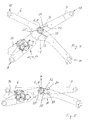
- FIGS. 2 and 3 show a window pane drive of a first embodiment of the invention, in which the gas tension spring 18 is replaced by a spring member 20.
- the drive corresponds with respect to the lifting and lowering mechanism with the lifting members 6 and 7 and the actuator 14 formed again as an electric motor to drive the FIG. 1 at least as far as relevant to the invention. It will therefore only the differences to the drive of FIG. 1 However, for the rest, reference is made to the description and the description there.
- the lifting and lowering mechanism in each one of its two extreme states, in FIG. 2 in the extended and in FIG. 3 in retracted state. From the extended state, the mechanism can be moved in the direction indicated by the direction of arrow opening direction -Z to the retracted state and from this again in the closing direction Z to the extended state.
- the spring member 20 is an elongated, rod-shaped single-leaf spring, the retraction, the movement in the opening direction -Z, between a first spring end 21 and a second spring end 22nd elastically stressed on bending.
- the spring member 20 is advantageously dimensioned so that its restoring spring force, the weight of the window 5 ( FIG. 1 ) carries in each state of movement of the lifting and lowering mechanism and thus the actuator 14 and as in the drive of the FIG. 1 formed reduction gear 15 to 17 completely relieved.
- the spring member 20 is preferably further dimensioned so that it keeps the holder 8 with the window pane 5 in the closed state under the usual operating conditions, in particular road conditions, such as a bumpy track, in the closed state and thus the window closed.
- the spring member 20 is installed in preferred embodiments with a bias, so biased even in the fully extended state of the lifting and lowering mechanism, so that it opposes an unwanted retraction sufficient spring force.
- the spring force is advantageously at least 2500 N, and may in particular be about 3000 N.
- the biasing force for jamming is preferably at least 1000 N.
- the spring member 20 is supported on the first spring end 21 on a support 23 of the first lifting member 6 and the second spring end 22 on a support 24 of the second lifting member 7 from.
- the spring member 20 is further supported in a the spring ends 21 and 22 connecting spring portion with its under bending stress on the underside claimed at a further support 25 of the first lifting member 6 from.
- the spring member 20 between the spring ends 21 and 22 thus bent over the further support 25 and thereby about a spring axis A, which extends parallel to the hinge axis R of the connecting joint of the lifting members 6 and 7.
- the first spring end 21 and the support 23 together form a hinge in which the first spring end 21 is rotatable relative to the support 23 and thus to the lifting member 6 about a hinge axis determined by the support 23, which is parallel to the spring axis A, but relatively to the lifting member 6 can perform no translational movements in the radial and not in the tangential direction to the spring axis A.
- the second spring end 22 presses on the stressed in bending stress on the outside of the spring member 20 against the support 24 of the lifting member 7, which forms a stop contact for the spring end 22, the contact in a movement of the spring end 20 relative to the support 24 in the longitudinal direction of the spring member 20th allows.
- the support 24 or the further support 25 may or may advantageously each be advantageously formed as a roller or comparable rotary body with a rotation axis parallel to the spring axis A. This is advantageous in particular for the support 24 in order to reduce friction as much as possible in contact.
- both the pressure contact with the further support 25 and also in the pressure contact with the support 24 may be a pure sliding contact.
- the support 24 or 25 consist of a sliding material with a low coefficient of friction or be coated with the sliding material.
- the spring member 20 may be coated with the sliding material.
- 21 to 23 friction-reducing measures are taken for the hinge.
- the pin may consist of a sliding material with a low coefficient of sliding friction or be coated on the peripheral surface with a sliding material.
- the support 23 for the first spring end 21 is arranged closer to the joint 11 than at the joint axis R of the lifting members 6 and 7.
- the spring member 20 extends from the first spring end 21 in the direction of the hinge axis R such that an imaginary, straight extension of the spring member 20, the hinge axis R crossed at a small distance.
- the support 24 is disposed on the second lifting member 7 in a corresponding proximity to the hinge axis R. The support 24 performs when retracting in the opening direction -Z about the hinge axis R pivotal movement with a correspondingly short pivot arm and presses on the second spring end 22, whereby the spring member 20 in the relative movement of the lifting members 6 and 7 in the opening direction -Z to the Spring axis A is bent elastically.
- the spring member 20 has undergone the maximum bending deformation.
- the length of the spring member 20 and the arrangement of the supports 23 to 25 is selected so that the second spring end 22 by the relative movement of the lifting members 6 and 7 from the closed state to the open state relative to the first spring end 21 a relative stroke of 20 to 30 mm at a between the spring ends 21 and 22 measured total length of the spring member 20 of at least 150 mm and at most 500 mm performs.
- the spring member 20 of the retraction movement of the lifting members 6 and 7 unlike the conventional attenuator 18 of FIG. 1 imposes no restriction, since the problem of a dead center movement does not occur.
- the lifting members 6 and 7 can, as far as the spring member 20 is concerned, be pivoted into their overlap if their own geometry and the outer linkages 9, 11 and 13 on the vehicle door allow it.
- the pivot angle of the lifting members 6 and 7 during retraction and extension about 70 °. The drive thus builds in the direction of extension and retraction ⁇ Z very compact or can be retracted to a very low height.
- the spring member 20 can be arranged between outer side parts of the lifting members 6 and 7.
- the lifting members 6 and 7 are joined parts, each with side parts and these axially, d. H. parallel to the hinge axis R interconnecting webs.
- Such webs can in particular form the supports 23 to 25, which thus axially stiffen the side parts of the lifting members 6 and 7 against each other and thereby assume their respective support function for the spring member 20,
- FIGS. 4 and 5 show a window pane drive of a second embodiment of the invention, with respect to the transmission mechanism for raising and lowering the window pane 5, that is, in terms of the lifting and lowering mechanism, that of FIGS. 2 and 3 and thus the FIG. 1 equivalent.
- the joints or joint element 9, 11 and 13 are as in FIG. 2 each only indicated and also correspond as in the first embodiment of the respective embodiment in the FIG. 1 , The same applies to the actuator 14 and the reduction gear 15 to 17. In this regard, as to the first embodiment of the comments on FIG. 1 directed.
- the second embodiment differs from the first by the spring member 30.
- the hinge axis R of the lifting members 6 and 7 with the spring axis A of the spring member 30 together by the spring member 30 is bent about the hinge and spring axis R and A respectively.
- the spring member 30 can either be bent only over an angle of less than 360 ° about the hinge and spring axes R and A or at least once or several times completely wound around the axis R and A respectively.
- the spring member 30 may be a leg spring or in a further modification advantageously also a spiral spring, also with the hinge axis R as the spring axis A.
- the first spring end 31 is at a distance from the joint and spring axis R and A on an outer side facing away from this axis R and A on a support 33 of the whippen 6 and at a second spring end 32 at a likewise at a distance from the axis R and A arranged support 34 of the lifting member 7 supported.
- the supports 33 and 34 are arranged symmetrically with respect to a joint and spring axis R and A containing plane and move when retracting the lifting and lowering mechanism, in the opening direction -Z in the direction of this plane of symmetry towards each other, so lead one Relativhub, wherein the spring member 30 is subjected to the spring axis A and R of an elastic bending load and the retraction movement in the opening direction -Z opposes its elastic spring force.
- the movement in the opposite direction, the closing direction Z is supported accordingly.
- the spring member 30 is designed as a leaf spring, forms an axis or wave structure 35 of the joint of the lifting members 6 and 7, a further support comparable to the support 25 of the first embodiment.
- the axle or shaft structure 35 serves primarily as a guide for such a spring member 30.
- a spiral spring such a spring member with a first, radially inner spring end would be secured against rotation with a joint element of the joint forming wave structure , Pin or socket, the first lift member 6 connected.
- the second, radially outer spring end would be connected to a support of the second lifting member 7, which could basically be formed unchanged by the support 34.
- FIGS. 6 and 7 show a window pane drive of a third embodiment of the invention, with respect to the transmission mechanism for raising and lowering the window pane 5, that is, in terms of the lifting and lowering mechanism, that of FIGS. 2 and 3 and thus the FIG. 1 equivalent.
- the joints or joint element 9, 11 and 13 are as in FIG. 2 each only indicated and also correspond as in the first and second embodiments of the respective embodiment in the FIG. 1 , The same applies to the actuator 14 and the reduction gear 15 to 17. In this regard, as to the first embodiment of the comments on FIG. 1 directed.
- the spring member 40 is a coil spring.
- the spring member 40 is fixed with its spring end 41 on the lifting member 6, with its spring end 42 on the lifting member 7.
- the spring ends 41, 42 may be rotatably mounted in their respective attachment point or their respective attachment point to the lifting members 6, 7, so that at a Opening or closing movement of the window, the two spring ends 41, 42 and the central axis of the spring member 40 are at all times substantially on a straight line.
- a single or one guide for example one or a respective groove, may be present on one or both of the lifting members 6, 7, in which the fastening point for the respective spring end 41 or 42 relative to the respective lifting member 6 or 7 can move. That is, at least one of the attachment points in this embodiment is an element that can be preferably captive inserted into the associated groove, not shown, and that can move along the groove or other formed guide.
- the spring member 40 may be surrounded by a telescoping sleeve, or a telescoping rod may guide the spring element 40 inside the spring element.
- the outer and innermost telescoping element of the sleeve or the rod may be connected to the respective end of the spring element 40, or these telescoping elements are directly attached to the lifting members 6, 7 in the region of the respective spring end 41, 42. In this case applies to the attachment of the telescopic elements to what the attachment points of the spring ends said accordingly.
- the window pane drive is shown in the state with the window closed. That is, the spring member 40 is in a preloaded state and, in this position, prevents the window from opening by gravity alone. From this position, the window can be opened by means of the actuator 14, wherein the actuator 14 has to open the window against the spring force of the spring member 40.
- FIG. 7 shows the state of the window pane drive with the window open.
- the spring member 40 has been resiliently compressed and serves as a reservoir of spring energy that can assist the actuator 14 when the window is to be closed again.
- the stored spring energy corresponds substantially to the weight of the window, that is, the actuator only has to cause the closing of the window to move without having to lift the weight of the window. This task is taken over by the spring member 40, which is biased towards the closed window with the window open.
- the spring axis A coincides with the longitudinal axis of the spring member 40.
- the spring axis A extends at least substantially through the attachment points or support points of the spring member 40, on which this is supported on the gear members 6 and 7.
- the spring axis A performs at least substantially a pivoting movement about the support point of the first spring end 41 during the opening and closing movement of the transmission mechanism.
- the spring axis A always has a direction parallel to the opening and closing direction Z direction component. A relation to the opening and closing direction Z existing inclination is, however, increased when opening the window in the direction of movement -Z, d. H. the acute angle included with the direction ⁇ Z increases as it moves in the -Z direction.
- the spring axis A always has tangential to the hinge axis R and passes them in a relatively small radial distance.
- FIGS. 6 and 7 a combination of spring members 20 and 40 is shown, which together have the described bias for closing and holding the closed window.
- the purpose of using two different spring members may be, for example, a safety aspect, so that in case of failure of one of the spring members is still a support of the window is ensured during closing.
- the spring members 20 and 30 or the spring members 30 and 40 may be disposed in the same windowpane drive in the manner disclosed to collectively produce the desired spring force.
- per window pane drive or per window pane or holder 8 just in each case a single spring member, for example only one of the spring members 20, 30 and 40 used.
Landscapes
- Engineering & Computer Science (AREA)
- Mechanical Engineering (AREA)
- Power-Operated Mechanisms For Wings (AREA)
Applications Claiming Priority (2)
| Application Number | Priority Date | Filing Date | Title |
|---|---|---|---|
| DE202009014756U DE202009014756U1 (de) | 2009-11-05 | 2009-11-05 | Fensterscheibenantrieb mit Schließfeder |
| DE202010009486U DE202010009486U1 (de) | 2009-11-05 | 2010-06-24 | Fensterscheibenantrieb mit Schließfeder |
Publications (2)
| Publication Number | Publication Date |
|---|---|
| EP2320017A2 true EP2320017A2 (fr) | 2011-05-11 |
| EP2320017A3 EP2320017A3 (fr) | 2012-11-07 |
Family
ID=41795573
Family Applications (1)
| Application Number | Title | Priority Date | Filing Date |
|---|---|---|---|
| EP10190280A Withdrawn EP2320017A3 (fr) | 2009-11-05 | 2010-11-05 | Entraînement de vitre de fenêtre doté d'un ressort de fermeture |
Country Status (2)
| Country | Link |
|---|---|
| EP (1) | EP2320017A3 (fr) |
| DE (2) | DE202009014756U1 (fr) |
Families Citing this family (1)
| Publication number | Priority date | Publication date | Assignee | Title |
|---|---|---|---|---|
| DE102013214453B9 (de) * | 2013-07-24 | 2019-06-27 | Ovalo Gmbh | Linearversteller |
Citations (1)
| Publication number | Priority date | Publication date | Assignee | Title |
|---|---|---|---|---|
| DE202007014541U1 (de) | 2007-10-17 | 2009-03-12 | Edag Gmbh & Co. Kgaa | Fensterscheibenantrieb |
Family Cites Families (5)
| Publication number | Priority date | Publication date | Assignee | Title |
|---|---|---|---|---|
| FR2134858A5 (fr) * | 1971-04-22 | 1972-12-08 | Chrysler France | |
| US3926066A (en) * | 1974-05-28 | 1975-12-16 | Ford Motor Co | Power operated window regulator mechanism |
| FR2455667A1 (fr) * | 1979-05-04 | 1980-11-28 | Paumellerie Electrique | Leve-glace |
| DE19943652C1 (de) * | 1999-09-13 | 2001-01-25 | Brose Fahrzeugteile | Mitnehmer für einen einsträngigen Seil- oder Rohrfensterheber |
| DE202005013376U1 (de) * | 2005-04-13 | 2005-12-22 | Fes Gmbh Fahrzeug-Entwicklung Sachsen | Scheibenheber für Sicherheitsfahrzeuge |
-
2009
- 2009-11-05 DE DE202009014756U patent/DE202009014756U1/de not_active Expired - Lifetime
-
2010
- 2010-06-24 DE DE202010009486U patent/DE202010009486U1/de not_active Expired - Lifetime
- 2010-11-05 EP EP10190280A patent/EP2320017A3/fr not_active Withdrawn
Patent Citations (1)
| Publication number | Priority date | Publication date | Assignee | Title |
|---|---|---|---|---|
| DE202007014541U1 (de) | 2007-10-17 | 2009-03-12 | Edag Gmbh & Co. Kgaa | Fensterscheibenantrieb |
Also Published As
| Publication number | Publication date |
|---|---|
| DE202010009486U1 (de) | 2010-10-14 |
| DE202009014756U1 (de) | 2010-03-04 |
| EP2320017A3 (fr) | 2012-11-07 |
Similar Documents
| Publication | Publication Date | Title |
|---|---|---|
| EP2318631B1 (fr) | Véhicule automobile comprenant un mécanisme pour mouvoir un panneau ou une porte | |
| DE102004041358B4 (de) | Obentürschließer | |
| EP2614974B1 (fr) | Système de store pour un véhicule automobile | |
| EP2845782B1 (fr) | Recouvrement de paroi latérale | |
| WO2004050406A1 (fr) | Portiere de vehicule | |
| EP3656960B1 (fr) | Cinématique pour volet de véhicule | |
| DE102015207562A1 (de) | Dachintegrierter Heckklappenantrieb | |
| DE102012221645B4 (de) | Federsystem für eine schwenkbare, in einer Schließlage verriegelbare Klappe eines Kraftfahrzeugs | |
| AT16417U1 (de) | Stellarmantrieb | |
| EP1722054B1 (fr) | Dispositif d'arrêt pour une porte de véhicule et porte de véhicule pour un véhicule avec un tel dispositif d'arrêt | |
| DE10117769B4 (de) | Vorrichtung zur Unterstützung einer Öffnungsbewegung einer Fahrzeugklappe | |
| DE102005033098B4 (de) | Heckklappe für ein Kraftfahrzeug | |
| EP2320017A2 (fr) | Entraînement de vitre de fenêtre doté d'un ressort de fermeture | |
| DE10331692A1 (de) | Vorrichtung zur Führung einer Heckklappe an einem Fahrzeug | |
| EP1908892B1 (fr) | Lucarne | |
| DE102008018331A1 (de) | Hubflügeltür für eine Fahrzeugkarosserie | |
| DE102008061395B4 (de) | Kraftfahrzeug mit Mechanismus zum Bewegen einer Klappe oder Scherentüre | |
| DE102013202801B4 (de) | Einrichtung zur motorischen Betätigung einer Kraftfahrzeug-Türe mit Feststellfunktion | |
| DE102011016729B4 (de) | Vorrichtung zum fremdkraftunterstützten Verschwenken einer Klappe oder Tür und Fahrzeug | |
| DE102009057214A1 (de) | Türfeststeller für eine Tür eines Kraftwagens und Lagerung für eine Tür eines Kraftwagens mit einem Türfeststeller | |
| DE102008045905A1 (de) | Kraftfahrzeug mit Spindelantrieb zum Bewegen einer Klappe | |
| EP2621755B1 (fr) | Siège de véhicule | |
| DE102008026597B4 (de) | Cabrioverdeckvorrichtung | |
| EP3336293A1 (fr) | Dispositif de positionnement pour une pièce de véhicule mobile par rapport à une carrosserie d'un véhicule | |
| DE19831783A1 (de) | Türschließer mit automatischer Schließbewegung und Kraftspeicher in der Führungsschiene |
Legal Events
| Date | Code | Title | Description |
|---|---|---|---|
| PUAI | Public reference made under article 153(3) epc to a published international application that has entered the european phase |
Free format text: ORIGINAL CODE: 0009012 |
|
| AK | Designated contracting states |
Kind code of ref document: A2 Designated state(s): AL AT BE BG CH CY CZ DE DK EE ES FI FR GB GR HR HU IE IS IT LI LT LU LV MC MK MT NL NO PL PT RO RS SE SI SK SM TR |
|
| AX | Request for extension of the european patent |
Extension state: BA ME |
|
| RAP1 | Party data changed (applicant data changed or rights of an application transferred) |
Owner name: VPS VEHICLE PROTECTION SYSTEMS GMBH |
|
| PUAL | Search report despatched |
Free format text: ORIGINAL CODE: 0009013 |
|
| AK | Designated contracting states |
Kind code of ref document: A3 Designated state(s): AL AT BE BG CH CY CZ DE DK EE ES FI FR GB GR HR HU IE IS IT LI LT LU LV MC MK MT NL NO PL PT RO RS SE SI SK SM TR |
|
| AX | Request for extension of the european patent |
Extension state: BA ME |
|
| RIC1 | Information provided on ipc code assigned before grant |
Ipc: E05F 11/44 20060101AFI20121003BHEP |
|
| STAA | Information on the status of an ep patent application or granted ep patent |
Free format text: STATUS: THE APPLICATION IS DEEMED TO BE WITHDRAWN |
|
| 18D | Application deemed to be withdrawn |
Effective date: 20130508 |