EP3656960B1 - Cinématique pour volet de véhicule - Google Patents
Cinématique pour volet de véhicule Download PDFInfo
- Publication number
- EP3656960B1 EP3656960B1 EP19210141.8A EP19210141A EP3656960B1 EP 3656960 B1 EP3656960 B1 EP 3656960B1 EP 19210141 A EP19210141 A EP 19210141A EP 3656960 B1 EP3656960 B1 EP 3656960B1
- Authority
- EP
- European Patent Office
- Prior art keywords
- actuator
- gear
- length
- spindle
- relative
- Prior art date
- Legal status (The legal status is an assumption and is not a legal conclusion. Google has not performed a legal analysis and makes no representation as to the accuracy of the status listed.)
- Active
Links
Images




Classifications
-
- E—FIXED CONSTRUCTIONS
- E05—LOCKS; KEYS; WINDOW OR DOOR FITTINGS; SAFES
- E05F—DEVICES FOR MOVING WINGS INTO OPEN OR CLOSED POSITION; CHECKS FOR WINGS; WING FITTINGS NOT OTHERWISE PROVIDED FOR, CONCERNED WITH THE FUNCTIONING OF THE WING
- E05F15/00—Power-operated mechanisms for wings
- E05F15/60—Power-operated mechanisms for wings using electrical actuators
- E05F15/603—Power-operated mechanisms for wings using electrical actuators using rotary electromotors
- E05F15/611—Power-operated mechanisms for wings using electrical actuators using rotary electromotors for swinging wings
- E05F15/616—Power-operated mechanisms for wings using electrical actuators using rotary electromotors for swinging wings operated by push-pull mechanisms
- E05F15/622—Power-operated mechanisms for wings using electrical actuators using rotary electromotors for swinging wings operated by push-pull mechanisms using screw-and-nut mechanisms
-
- B—PERFORMING OPERATIONS; TRANSPORTING
- B60—VEHICLES IN GENERAL
- B60J—WINDOWS, WINDSCREENS, NON-FIXED ROOFS, DOORS, OR SIMILAR DEVICES FOR VEHICLES; REMOVABLE EXTERNAL PROTECTIVE COVERINGS SPECIALLY ADAPTED FOR VEHICLES
- B60J5/00—Doors
- B60J5/04—Doors arranged at the vehicle sides
- B60J5/047—Doors arranged at the vehicle sides characterised by the opening or closing movement
-
- B—PERFORMING OPERATIONS; TRANSPORTING
- B60—VEHICLES IN GENERAL
- B60J—WINDOWS, WINDSCREENS, NON-FIXED ROOFS, DOORS, OR SIMILAR DEVICES FOR VEHICLES; REMOVABLE EXTERNAL PROTECTIVE COVERINGS SPECIALLY ADAPTED FOR VEHICLES
- B60J5/00—Doors
- B60J5/04—Doors arranged at the vehicle sides
- B60J5/06—Doors arranged at the vehicle sides slidable; foldable
- B60J5/062—Doors arranged at the vehicle sides slidable; foldable for utility vehicles or public transport
-
- E—FIXED CONSTRUCTIONS
- E05—LOCKS; KEYS; WINDOW OR DOOR FITTINGS; SAFES
- E05F—DEVICES FOR MOVING WINGS INTO OPEN OR CLOSED POSITION; CHECKS FOR WINGS; WING FITTINGS NOT OTHERWISE PROVIDED FOR, CONCERNED WITH THE FUNCTIONING OF THE WING
- E05F15/00—Power-operated mechanisms for wings
- E05F15/60—Power-operated mechanisms for wings using electrical actuators
- E05F15/603—Power-operated mechanisms for wings using electrical actuators using rotary electromotors
- E05F15/611—Power-operated mechanisms for wings using electrical actuators using rotary electromotors for swinging wings
- E05F15/63—Power-operated mechanisms for wings using electrical actuators using rotary electromotors for swinging wings operated by swinging arms
-
- F—MECHANICAL ENGINEERING; LIGHTING; HEATING; WEAPONS; BLASTING
- F16—ENGINEERING ELEMENTS AND UNITS; GENERAL MEASURES FOR PRODUCING AND MAINTAINING EFFECTIVE FUNCTIONING OF MACHINES OR INSTALLATIONS; THERMAL INSULATION IN GENERAL
- F16H—GEARING
- F16H1/00—Toothed gearings for conveying rotary motion
- F16H1/02—Toothed gearings for conveying rotary motion without gears having orbital motion
- F16H1/04—Toothed gearings for conveying rotary motion without gears having orbital motion involving only two intermeshing members
- F16H1/12—Toothed gearings for conveying rotary motion without gears having orbital motion involving only two intermeshing members with non-parallel axes
- F16H1/14—Toothed gearings for conveying rotary motion without gears having orbital motion involving only two intermeshing members with non-parallel axes comprising conical gears only
-
- F—MECHANICAL ENGINEERING; LIGHTING; HEATING; WEAPONS; BLASTING
- F16—ENGINEERING ELEMENTS AND UNITS; GENERAL MEASURES FOR PRODUCING AND MAINTAINING EFFECTIVE FUNCTIONING OF MACHINES OR INSTALLATIONS; THERMAL INSULATION IN GENERAL
- F16H—GEARING
- F16H25/00—Gearings comprising primarily only cams, cam-followers and screw-and-nut mechanisms
- F16H25/18—Gearings comprising primarily only cams, cam-followers and screw-and-nut mechanisms for conveying or interconverting oscillating or reciprocating motions
- F16H25/20—Screw mechanisms
-
- F—MECHANICAL ENGINEERING; LIGHTING; HEATING; WEAPONS; BLASTING
- F16—ENGINEERING ELEMENTS AND UNITS; GENERAL MEASURES FOR PRODUCING AND MAINTAINING EFFECTIVE FUNCTIONING OF MACHINES OR INSTALLATIONS; THERMAL INSULATION IN GENERAL
- F16H—GEARING
- F16H37/00—Combinations of mechanical gearings, not provided for in groups F16H1/00 - F16H35/00
- F16H37/12—Gearings comprising primarily toothed or friction gearing, links or levers, and cams, or members of at least two of these types
- F16H37/124—Gearings comprising primarily toothed or friction gearing, links or levers, and cams, or members of at least two of these types for interconverting rotary motion and reciprocating motion
-
- E—FIXED CONSTRUCTIONS
- E05—LOCKS; KEYS; WINDOW OR DOOR FITTINGS; SAFES
- E05D—HINGES OR SUSPENSION DEVICES FOR DOORS, WINDOWS OR WINGS
- E05D15/00—Suspension arrangements for wings
- E05D15/06—Suspension arrangements for wings for wings sliding horizontally more or less in their own plane
- E05D15/10—Suspension arrangements for wings for wings sliding horizontally more or less in their own plane movable out of one plane into a second parallel plane
- E05D15/1005—Suspension arrangements for wings for wings sliding horizontally more or less in their own plane movable out of one plane into a second parallel plane the wing being supported on arms movable in horizontal planes
-
- E—FIXED CONSTRUCTIONS
- E05—LOCKS; KEYS; WINDOW OR DOOR FITTINGS; SAFES
- E05D—HINGES OR SUSPENSION DEVICES FOR DOORS, WINDOWS OR WINGS
- E05D15/00—Suspension arrangements for wings
- E05D15/06—Suspension arrangements for wings for wings sliding horizontally more or less in their own plane
- E05D15/10—Suspension arrangements for wings for wings sliding horizontally more or less in their own plane movable out of one plane into a second parallel plane
- E05D15/1005—Suspension arrangements for wings for wings sliding horizontally more or less in their own plane movable out of one plane into a second parallel plane the wing being supported on arms movable in horizontal planes
- E05D15/1007—Suspension arrangements for wings for wings sliding horizontally more or less in their own plane movable out of one plane into a second parallel plane the wing being supported on arms movable in horizontal planes specially adapted for use in railway-cars or mass transit vehicles
-
- E—FIXED CONSTRUCTIONS
- E05—LOCKS; KEYS; WINDOW OR DOOR FITTINGS; SAFES
- E05D—HINGES OR SUSPENSION DEVICES FOR DOORS, WINDOWS OR WINGS
- E05D15/00—Suspension arrangements for wings
- E05D15/28—Suspension arrangements for wings supported on arms movable in horizontal plane
-
- E—FIXED CONSTRUCTIONS
- E05—LOCKS; KEYS; WINDOW OR DOOR FITTINGS; SAFES
- E05F—DEVICES FOR MOVING WINGS INTO OPEN OR CLOSED POSITION; CHECKS FOR WINGS; WING FITTINGS NOT OTHERWISE PROVIDED FOR, CONCERNED WITH THE FUNCTIONING OF THE WING
- E05F15/00—Power-operated mechanisms for wings
- E05F15/60—Power-operated mechanisms for wings using electrical actuators
- E05F15/603—Power-operated mechanisms for wings using electrical actuators using rotary electromotors
-
- E—FIXED CONSTRUCTIONS
- E05—LOCKS; KEYS; WINDOW OR DOOR FITTINGS; SAFES
- E05Y—INDEXING SCHEME ASSOCIATED WITH SUBCLASSES E05D AND E05F, RELATING TO CONSTRUCTION ELEMENTS, ELECTRIC CONTROL, POWER SUPPLY, POWER SIGNAL OR TRANSMISSION, USER INTERFACES, MOUNTING OR COUPLING, DETAILS, ACCESSORIES, AUXILIARY OPERATIONS NOT OTHERWISE PROVIDED FOR, APPLICATION THEREOF
- E05Y2201/00—Constructional elements; Accessories therefor
- E05Y2201/60—Suspension or transmission members; Accessories therefor
- E05Y2201/622—Suspension or transmission members elements
- E05Y2201/686—Rods, links
-
- E—FIXED CONSTRUCTIONS
- E05—LOCKS; KEYS; WINDOW OR DOOR FITTINGS; SAFES
- E05Y—INDEXING SCHEME ASSOCIATED WITH SUBCLASSES E05D AND E05F, RELATING TO CONSTRUCTION ELEMENTS, ELECTRIC CONTROL, POWER SUPPLY, POWER SIGNAL OR TRANSMISSION, USER INTERFACES, MOUNTING OR COUPLING, DETAILS, ACCESSORIES, AUXILIARY OPERATIONS NOT OTHERWISE PROVIDED FOR, APPLICATION THEREOF
- E05Y2201/00—Constructional elements; Accessories therefor
- E05Y2201/60—Suspension or transmission members; Accessories therefor
- E05Y2201/622—Suspension or transmission members elements
- E05Y2201/696—Screw mechanisms
-
- E—FIXED CONSTRUCTIONS
- E05—LOCKS; KEYS; WINDOW OR DOOR FITTINGS; SAFES
- E05Y—INDEXING SCHEME ASSOCIATED WITH SUBCLASSES E05D AND E05F, RELATING TO CONSTRUCTION ELEMENTS, ELECTRIC CONTROL, POWER SUPPLY, POWER SIGNAL OR TRANSMISSION, USER INTERFACES, MOUNTING OR COUPLING, DETAILS, ACCESSORIES, AUXILIARY OPERATIONS NOT OTHERWISE PROVIDED FOR, APPLICATION THEREOF
- E05Y2201/00—Constructional elements; Accessories therefor
- E05Y2201/60—Suspension or transmission members; Accessories therefor
- E05Y2201/622—Suspension or transmission members elements
- E05Y2201/71—Toothed gearing
- E05Y2201/716—Pinions
- E05Y2201/718—Bevelled pinions
-
- E—FIXED CONSTRUCTIONS
- E05—LOCKS; KEYS; WINDOW OR DOOR FITTINGS; SAFES
- E05Y—INDEXING SCHEME ASSOCIATED WITH SUBCLASSES E05D AND E05F, RELATING TO CONSTRUCTION ELEMENTS, ELECTRIC CONTROL, POWER SUPPLY, POWER SIGNAL OR TRANSMISSION, USER INTERFACES, MOUNTING OR COUPLING, DETAILS, ACCESSORIES, AUXILIARY OPERATIONS NOT OTHERWISE PROVIDED FOR, APPLICATION THEREOF
- E05Y2900/00—Application of doors, windows, wings or fittings thereof
- E05Y2900/50—Application of doors, windows, wings or fittings thereof for vehicles
- E05Y2900/506—Application of doors, windows, wings or fittings thereof for vehicles for buses
-
- E—FIXED CONSTRUCTIONS
- E05—LOCKS; KEYS; WINDOW OR DOOR FITTINGS; SAFES
- E05Y—INDEXING SCHEME ASSOCIATED WITH SUBCLASSES E05D AND E05F, RELATING TO CONSTRUCTION ELEMENTS, ELECTRIC CONTROL, POWER SUPPLY, POWER SIGNAL OR TRANSMISSION, USER INTERFACES, MOUNTING OR COUPLING, DETAILS, ACCESSORIES, AUXILIARY OPERATIONS NOT OTHERWISE PROVIDED FOR, APPLICATION THEREOF
- E05Y2900/00—Application of doors, windows, wings or fittings thereof
- E05Y2900/50—Application of doors, windows, wings or fittings thereof for vehicles
- E05Y2900/53—Type of wing
- E05Y2900/531—Doors
-
- F—MECHANICAL ENGINEERING; LIGHTING; HEATING; WEAPONS; BLASTING
- F16—ENGINEERING ELEMENTS AND UNITS; GENERAL MEASURES FOR PRODUCING AND MAINTAINING EFFECTIVE FUNCTIONING OF MACHINES OR INSTALLATIONS; THERMAL INSULATION IN GENERAL
- F16H—GEARING
- F16H25/00—Gearings comprising primarily only cams, cam-followers and screw-and-nut mechanisms
- F16H25/18—Gearings comprising primarily only cams, cam-followers and screw-and-nut mechanisms for conveying or interconverting oscillating or reciprocating motions
- F16H25/20—Screw mechanisms
- F16H2025/2062—Arrangements for driving the actuator
- F16H2025/2084—Perpendicular arrangement of drive motor to screw axis
Definitions
- the present invention relates to an actuator which is designed to displace two higher-level assemblies, between which the actuator is arranged, relative to one another.
- Such actuators are known, for example, in the field of vehicle doors, such as swing doors on buses. The invention will therefore be described below with reference to this application, although it is expressly pointed out that the invention is of course not limited to this.
- rigid coupling rods which are connected on the one hand to a body of the vehicle and on the other hand to the door. If the door is now displaced relative to the body, the door follows a path predetermined by the coupling rods. Since the path of the possible displacement of the door relative to the body is usually circular, the attachment point of the coupling rods on the body is predetermined. Furthermore, the door usually initially pivots far away from the body due to the rigid coupling rod until it rests against the body in its open state.
- Such an actuator enables two combined movements. Firstly, a rotation of the spindle drive, and thus of the first higher-level assembly connected to the spindle drive, relative to the second higher-level assembly and secondly, a translational displacement of the first higher-level assembly relative to the axis of rotation of the spindle drive relative to the second higher-level assembly.
- a “rotation of the spindle drive” can be understood to mean that the entire spindle drive or at least the spindle and the spindle nut are displaced together.
- a “rotation of the spindle drive” means that a central axis of the spindle and/or the spindle nut is rotated about an element connected to the second higher-level assembly, for example a central axis of the second connecting unit or a central axis of the second gear.
- an "inclination" of the longitudinal axis of the spindle drive to the central axis of the second gear can include any inclination deviating from coaxiality, for example 30°, 45° or 90°.
- the first higher-level assembly which is formed, for example, by a door that is to be pivoted, can thus be displaced along an elliptical path or along a circular path whose center lies outside the actuator.
- the two end positions of an entire displacement range of the first higher-level assembly for example a first end position in which the door closes a passage area and a second end position in which the door is displaced out of the passage area and rests against a vehicle body, can thus be arranged further apart from one another. This in turn makes it possible to create larger passage areas.
- At least one of the first gear and the second gear may be a bevel gear or a crown gear, which may be inclined to each other according to the "inclination" described above.
- the actuator can be designed in such a way that a predetermined activation position of the spindle drive is assigned exactly one angular position of the displacement of the spindle drive relative to the center axis of the second gear and vice versa.
- a displacement of the spindle or the spindle nut is accompanied by a forced displacement of the spindle drive around the center axis of the second gear.
- every angle of the spindle drive around this central axis is assigned to exactly one elongation of the spindle drive. This prevents the first connecting unit from assuming more than one single predetermined position in three-dimensional space when the spindle drive angle remains constant around the central axis, ie relative to the second higher-level assembly.
- the second gear can be rotationally coupled to a housing surrounding the second gear, and the actuator can be designed such that a relative displacement of the two gears to one another causes a rotation of the housing relative to the second connection unit.
- a rotation of the second gear can cause a rotation of the housing.
- the spindle drive which can also be arranged in a housing, for example, is connected to the housing surrounding the second gear, for example via the housing of the spindle drive, the rotation of the housing can also cause a rotation of the spindle drive.
- a rotation of the second gear can, on the one hand, activate the spindle drive and, on the other hand, drive a rotation of the housing surrounding the second gear.
- a gear can be arranged between the second gear and the housing, which provides a transmission between a rotation of the second gear and a rotation of the housing.
- the gear can translate a first rotational speed and/or a first torque of the rotation of the second gear on the gear side of the gear into a second rotational speed and/or a second torque on the housing side of the gear.
- the gear can engage with the second gear via a first thread having a first thread pitch and with the housing via a second thread having a second thread pitch, wherein the first thread pitch is separated from the second thread pitch can be different.
- the thread pitches are selected such that a rotational speed of the housing, and thus possibly of the spindle drive, relative to the second higher-level assembly, is smaller than a rotational speed of the spindle or the spindle nut of the spindle drive.
- the ratio of the first thread pitch to the second thread pitch By setting the ratio of the first thread pitch to the second thread pitch, it can be defined over which angular range the spindle drive is pivoted while it moves from a first, for example fully retracted, end position to a second, for example fully extended, end position.
- the two threads each have constant, but possibly different, thread pitches, or that each thread has thread sections with varying thread pitches.
- an elongation of the spindle drive in a first predefined angular range of the pivoting of the spindle drive or the housing relative to the second higher-level assembly can be less than in a second predefined such angular range.
- the gear can further comprise an intermediate piece which is in threaded engagement with the housing and the second gear, and which is coupled to the second connecting unit in a rotationally fixed but axially displaceable manner.
- the arrangement of an intermediate piece which has two separate thread sections which have different thread pitches can avoid the provision of a complex gear arrangement, such as a planetary gear. This can significantly reduce both the required installation space and the susceptibility of the arrangement to errors.
- the actuator comprises a drive unit, in particular an electric motor which is configured to drive at least one of the first gear, the second gear, the spindle, the spindle nut and the housing.
- the drive unit can be configured to receive an activation signal which indicates at least one of a direction of rotation and a rotation speed in which the drive unit is to be driven.
- the invention in a second aspect, relates to a mounting device for a flap, in particular a pivoting door, comprising a four-bar arrangement which comprises two coupling rods arranged parallel to one another and laterally spaced from one another, which are pivotally connected at their respective one end to a higher-level assembly, in particular a vehicle body, a pivoting element with which the coupling rods of the four-bar arrangement are pivotally connected at their respective other end, in particular adjacent to an edge of the pivoting element, and an actuator according to the invention with one of the features mentioned above, which is pivotally connected at its one end to the higher-level assembly and is pivotally connected at its other end to the pivoting element, and which is designed to displace the pivoting element relative to the higher-level assembly upon activation of the actuator.
- Pivoting elements in particular vehicle doors, are known from the prior art, which are connected to a vehicle body at their vertical longitudinal ends via a respective four-bar arrangement.
- These four-bar arrangements are difficult to disguise, i.e. to integrate into the design of a vehicle, and sometimes take up a lot of space in the interior of a vehicle when closed. Due to the large installation space of such a four-bar arrangement, especially when the door is closed, and the desire to clear an entire entry area in the open position, only small door widths can be implemented. Wide entry areas are often implemented using two opposing doors with respective four-bar arrangements. Such a four-bar arrangement often cannot be installed, particularly in the area of curved roof structures.
- the second aspect of the present invention can now make it possible to dispense with the upper four-bar arrangement, i.e. to provide only a single four-bar arrangement between the swivel element and the higher-level assembly.
- the actuator can be a rotary drive, for example arranged in a joint.
- the swivel element can be connected to the coupling rods of the four-bar arrangement using ball joints, so that not only swiveling between the swivel element and the coupling rods, but also tilting is permitted. In this way, tolerances and deviations in the trajectories of the four-bar arrangement and the actuator can be compensated.
- the actuator may comprise a coupling rod which is parallel to the coupling rods of the four-bar arrangement and laterally spaced from these, in particular equally spaced from them.
- the coupling rod is arranged, viewed in a vertical direction or along a horizontal direction, between the coupling rods of the four-bar arrangement, it is possible to reduce the installation space required for mounting the swivel element on the higher-level assembly.
- the two coupling rods of the four-bar arrangement or the two coupling rods of the four-bar arrangement and the coupling rod of the actuator can have the same length. If the connection points of all coupling rods on the higher-level assembly and/or on the swivel element are arranged on a common, preferably vertical, plane, it can be made possible for the swivel element to remain aligned parallel to this plane during swiveling. In other words, this can prevent the swivel element from tilting out of a vertical alignment, for example.
- the actuator can, in an operational state of the bearing device, be arranged vertically above the four-bar arrangement, in particular in the region of half of a vertical extension of the swivel element.
- the four-bar arrangement can be arranged in the region of a floor of a vehicle, so that the four-bar arrangement can take up sufficient installation space without affecting a passenger compartment and/or an external design of the vehicle.
- the four-bar arrangement can therefore be designed to be very stable, so that it can, for example, completely bear the weight of an element to be swiveled.
- the actuator can now only be assigned the task of driving the element to be swiveled and preventing it from tipping out of a predefined orientation. Accordingly, the actuator can be designed to save space.
- the storage device according to the invention could also be designed for a window or the like instead of a swing door.
- a drive operated, for example, hydraulically, pneumatically or magnetically is provided, the activation of which is not mechanically coupled, but for example using a suitable measuring device.
- the "displacement of the length-adjustable section relative to a pivot axis of the length-adjustable section” does not necessarily mean that it is the length-adjustable section of the actuator that is visibly pivoted.
- the length-adjustable section can be connected to a vehicle body and a non-length-adjustable section of the actuator is pivoted. What is crucial is that a relative rotation is carried out between a length-adjustable section of the actuator and another section of the actuator while the length-adjustable section is activated, i.e. its length is changed.
- an actuator according to the invention which has a forced coupling between its change in length and its rotation, it is possible to vary the connection point of the actuator to the higher-level assembly almost as desired. Nevertheless, a displacement of the swivel element can be carried out, for example, parallel to an outer surface of the higher-level assembly.
- the actuator can be connected to the higher-level assembly at its end associated with the length-adjustable section and can comprise a spacer arranged between the length-adjustable section of the actuator and the pivoting element.
- a The spindle drive of the actuator can be connected to the vehicle body in such a way that when the spindle drive is activated, the end of the spindle drive connected to the spacer is displaced relative to the vehicle body.
- the spacer which is formed by a rigid rod, for example, is rotated relative to the spindle drive.
- Such an arrangement can result in a center of rotation of the spacer being displaced linearly in accordance with the change in length of the spindle drive.
- a pivoting element such as a door
- a pivoting element can be displaced not only in accordance with the pivoting range defined by the rotation of the spacer, but also in accordance with the stroke of the spindle drive. Since the pivot point of the hinge is displaced, this can result in an enlargement of a possible entry area, which is released by opening the door.
- additional coupling rods can be provided between the swivel element and the vehicle body for further storage and support, for example in the form of a four-bar arrangement.
- the arrangement of additional coupling rods and/or four-bar arrangements can be completely dispensed with. Furthermore, this makes it possible to move a door as far as possible from an entry area. With a suitable selection of the ratio of rotation to length change of the respective actuator, the connection of the respective actuator to the higher-level assembly can be selected almost freely.
- a thread pitch direction of a spindle of a first spindle drive of one actuator can be opposite to a thread pitch direction of a spindle of a second spindle drive of the other actuator.
- this makes it possible for the connection points of the two actuators to lie on a common axis, in particular parallel to a main extension direction of the pivot element, for example vertical. In this way, a parallel movement of the pivot element to the higher-level assembly can be achieved.
- the length-adjustable section of one actuator can thus be shortened, while at the same time the length-adjustable section of the other actuator is lengthened.
- the storage device according to the invention could be designed for a window or similar instead of a swing door.
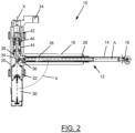
- an actuator according to the invention is generally provided with the reference number 10.
- the actuator 10 comprises a length-adjustable first section 12, which is formed here by a spindle drive 12.
- the spindle drive 12 comprises a casing tube 14, which is connected to a first connecting unit 16 in order to connect the actuator 10 to a first higher-level assembly (not shown).
- the spindle drive 12 is surrounded by a tube 18 which is firmly connected to a housing 20 of the actuator 10.
- the housing 20 is rotatably mounted relative to a second higher-level assembly (not shown) by two bearings 22. Furthermore, the actuator is attached to the second higher-level assembly by a second connection unit 24.
- the housing 20 is rotatably mounted relative to the second connection unit 24 but is axially fixed.
- a drive unit 30 is also shown, which is formed by an electric motor, for example.
- the drive unit 30 is connected to a gear unit 32, which is connected to an output shaft 34 on its side opposite the drive unit 30.
- a first gear 36 which is connected to the spindle 28 in a rotationally fixed manner, is in engagement with a second gear 38, which is connected to the output shaft 34 in a rotationally fixed manner. If the drive unit 30 now drives the output shaft 34 and thus the second gear 38, the first gear 36 is set in rotation together with the spindle 28. As a result, as mentioned above, the spindle nut 26 is displaced along an axis A, which here also forms a central axis of the spindle 28.
- the output shaft 34 On its side opposite the gear unit 32, the output shaft 34 has a first thread 40 which engages with a corresponding counter thread of an intermediate element 42.
- the intermediate element 42 is at a portion which is in the Figure 2 illustrated embodiments is arranged at an upper end of the intermediate element 42, mounted in a rotationally fixed but axially displaceable manner relative to the second connecting unit 24.
- a second thread 44 is arranged, which engages with a corresponding counter thread, which is firmly connected to the housing 20 or is formed on an inner side of the housing 20.
- the first thread 40 here has a significantly smaller thread pitch than the second thread 44.
- the intermediate element 42 Upon rotation of the output shaft 34, the intermediate element 42 is displaced axially in relation to the output shaft 34 or in relation to the second connection unit 24 via the first thread 40 and due to the axial toothing to the second connection unit 24 described above. Due to the second thread 44 between the intermediate element 42 and the housing 20, the housing 20 is set in rotation upon a translational displacement of the intermediate element 42.
- the housing 20 rotates about a pivot axis X, which here also forms a central axis of the output shaft 34 and/or the intermediate element 42 and/or the second gear 38.
- the actuator 10 can also be designed as a passive unit, that is to say at least without the drive unit 30, in which a rotation of the housing 20 causes a change in the length of the spindle drive 12 or a change in the length of the spindle drive 12 causes a rotation of the housing 20 relative to the second connecting unit 24, for example due to manual actuation.
- An angle ⁇ between the axis A and the swivel axis X is in the Figure 2 illustrated embodiment at approximately 90°.
- a door is shown as a pivoting element 102.
- the door 102 is shown completely or whether only, for example, a lower Half of the door 102 in Figure 3 is shown.
- the door 102 is connected to a vehicle body 106 by a four-bar arrangement 104.
- the four-bar arrangement 104 is formed here from two identical coupling rods arranged parallel to one another.
- the four-bar arrangement 104 is hinged to the vehicle body 106 in such a way that the coupling rods of the four-bar arrangement 104 can pivot relative to the vehicle body 106 along only a single, for example horizontal, plane.
- an actuator 10 is arranged between the door 102 and a section of the vehicle body 106 (not shown).
- the actuator 10 is aligned parallel to the coupling rods of the four-bar arrangement 104, so that the actuator 10 in the representation of the Figure 3 can also be a rotary drive with a rigid coupling rod between the rotary drive and the door 102.
- FIG 3 The state is shown in which the door 102 is pivoted out of an entry opening 108 of a vehicle comprising the vehicle body 106 in order to release the entry opening 108.
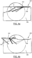
- a bearing device 200 is shown in which the "two-joint" with a fixed coupling rod is replaced by a length-adjustable actuator 10.
- the bearing device 200 shown in the Figures 4a and 4b shown arrangement 200 of a plan view of the in Figure 3 shown arrangement 100 to which reference is explicitly made at this point. Accordingly, only the differences between the arrangements shown in the Figures 4a and 4b shown arrangement 200 to that in the Figure 3 arrangement 100 shown.
- the actuator 10 of the bearing device 200 can be connected to the vehicle body 206 at almost any location.
- the actuator 10 seen in the vertical plan view of these figures, is arranged between the two coupling rods of the four-bar arrangement 204.
- the connection point between the actuator and the vehicle body 206 is not arranged centrally between the two coupling rods of the four-bar arrangement 204, but adjacent to the coupling rod of the four-bar arrangement 204 arranged away from the entry opening 208.
- the actuator of the storage device 200 can also be arranged, for example, halfway up the door 202, but in any case vertically above the four-bar arrangement 204.
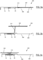
- FIGS. 5a to 5c show another possible arrangement of a storage device 300.
- FIG. 5a and 4b show the Figures 5a to 5c a door 302 which can close or open an entry opening 308 of a vehicle comprising a vehicle body 306.
- An actuator 10 according to the invention is connected to the vehicle body 306.
- the actuator 10 is connected with its free End of the variable length section connected to the vehicle body 306.
- the first connection unit 16 is connected to the vehicle body 306.
- a spacer 310 which is designed here as a rigid rod, is connected at one end to the housing 20 and at its other end to the door 302, wherein it is pivotally mounted on the door 302.
- the length-adjustable section for example the spindle drive 12
- the actuator 10 Upon activation of the actuator 10, which causes a forced change in length of the length-adjustable section and a rotation of the housing 20, and thus of the spacer 310, in the sequence of Figures 5a to 5c seen, the length-adjustable section, for example the spindle drive 12, of the actuator 10 is shortened and the housing 20 with the spacer 310 rotates relative thereto.
- the door is pivoted out of the access opening 308 in accordance with the rotation of the housing 20 and that at the same time the housing 20, and thus a pivot axis of the door 302, is displaced linearly in accordance with the shortening of the length-adjustable section of the actuator 10. Due to the coupled rotational and translational displacement of the door 302 from the access opening 308, a larger access area 308 can be opened or closed.
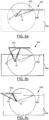
- the Figures 6a to 6c show a further storage device 400.
- the storage device 400 differs from the above-mentioned embodiments 100 to 300, to which reference is hereby made explicitly, in particular in that two positively coupled actuators, which are hereby realized as two actuators 10 and 10' according to the invention, are connected at one end to a vehicle body 406 and at the other end to a door 402.
- the door 402 is designed to close or open an access opening 408. In the following, therefore, only the differences from the embodiments mentioned above will be discussed.
- the two actuators 10 and 10' are arranged with their length-adjustable section, which in the embodiment shown here is formed by the spindle drive 12, between the vehicle body 406 and the door 402.
- the spindle drive 12 of the actuator 10 is articulated on an edge of the door 402, whereas the spindle drive 12 of the other actuator 10' is articulated in the region of a center of the door 402.
- connection points of the actuators 10 and 10' on the vehicle body 406 coincide.
- the thread pitch directions, i.e. the direction of rotation of the threads, of the spindle drives 12 of the actuator 10 and the further actuator 10' are opposite, so that when the two length-adjustable sections of the actuators 10 and 10' rotate in the same direction of rotation, one section is lengthened, whereas the other section is shortened.
- the door 402 can be displaced in parallel, i.e. an orientation of the door 402 to the vehicle body 406 remains constant during the displacement of the door 402.
- the door 402 is displaced out of the access opening 408 and is located approximately halfway between the displacement area the maximum positions of the Figures 6a and 6c .
- the length-adjustable sections of the actuators 10 and 10' are both located approximately halfway through their length-adjustable range. In particular, the length-adjustable sections of the actuators 10 and 10' are in the same position with respect to their length changeability.
- the two actuators 10 and 10' are arranged here, for example, on a lower edge of the door 402 and on a floor of the vehicle body 406.
- the two actuators 10 and 10' can also be realized by a second embodiment of an actuator 10A according to the invention, which is designed essentially identically to the actuator 10 according to the invention, but comprises two spindle drives, namely a first spindle drive 12A and a second spindle drive 12B, instead of one.
- the first spindle drive 12A and the second spindle drive 12B extend essentially at right angles from the housing 20A of the actuator 10A.
- the second spindle drive 12B is also driven by a gear 38A arranged in the housing 20A.
- the gear 38A which is also designed as a bevel gear However, it has not only a toothing to a gear 36B of the second spindle drive 12B, but also a toothing to a gear 36A of the first spindle drive 12A.
- the gear 38A can thus be regarded as a double bevel gear.
- the two spindle drives 12A and 12B can, for example, have thread pitches that are equal to one another, but increase in a direction opposite to one another.
- the first spindle drive 12A can be lengthened by a predetermined distance and the second spindle drive 12B can be shortened by the same distance.
- the two spindle drives 12A and 12B have different thread pitches or sections of different thread pitches in relation to one another.
Landscapes
- Engineering & Computer Science (AREA)
- General Engineering & Computer Science (AREA)
- Mechanical Engineering (AREA)
- Power-Operated Mechanisms For Wings (AREA)
- Transmission Devices (AREA)
- Lock And Its Accessories (AREA)
Claims (14)
- Actionneur (10, 10A) comprenantun entraînement de broche (12, 12A, 12B), qui comprend une broche (28) et un écrou de broche (26) en prise par filetage avec la broche (28),une première roue dentée (36) qui est couplée en rotation à la broche (28) ou à l'écrou de broche (26),dans lequel l'autre de l'écrou de broche (26) ou de la broche (28) est relié à une première unité de liaison (16) pour relier l'actionneur (10, 10A) à un premier ensemble supérieur (102, 202, 302, 402 ; 106, 206, 306, 406),dans lequel l'entraînement de broche (12, 12A, 12B) est conçu de telle sorte qu'une rotation de la première roue dentée (36) provoque un déplacement en translation de la première unité de liaison (16), etune deuxième roue dentée (38) qui est en prise avec la première roue dentée (36) et qui est couplée en rotation à une deuxième unité de liaison (24) pour relier l'actionneur (10, 10A) à un deuxième ensemble supérieur (106, 206, 306, 406 ; 102, 202, 302, 402),dans lequel un axe longitudinal (A) de l'entraînement de broche (12, 12A, 12B) est incliné par rapport à un axe central (X), en particulier par rapport à un axe de rotation (X), de la deuxième roue dentée (38),dans lequel l'actionneur (10, 10A) est conçu pour qu'une rotation relative des deux roues dentées (36, 38) l'une par rapport à l'autre déclenche un actionnement de l'entraînement de broche (12, 12A, 12B) ainsi qu'un déplacement de l'entraînement de broche (12, 12A, 12B) par rapport à l'axe central (X) du deuxième roue dentée (38) ou l'actionnement de l'entraînement de broche (12, 12A, 12B) provoque une rotation relative des deux roues dentées (36, 38) l'un par rapport à l'autre ainsi qu'un déplacement de l'entraînement de broche (12, 12A, 12B) par rapport à l'axe central (X) du deuxième roue dentée (38),dans lequel l'actionneur (10, 10A) comprend une unité d'entraînement (30), en particulier un moteur électrique, qui est adaptée pour entraîner au moins l'un de la première roue dentée (36), de la deuxième roue dentée (38), de la broche (28), de l'écrou de broche (26) et du boîtier (20).
- Actionneur (10, 10A) selon la revendication 1,
caractérisé en ce que l'actionneur (10, 10A) est configuré de telle sorte qu'à une position d'activation prédéterminée de l'entraînement de la broche (12, 12A, 12B) est associée précisément une position angulaire de déplacement de l'entraînement de la broche (12, 12A, 12B) par rapport à l'axe central (X) de la deuxième roue dentée (38) et inversement. - Actionneur (10, 10A) selon la revendication 1 ou 2,
caractérisé en ce que la deuxième roue dentée (38) est couplée en rotation à un boîtier (20) entourant la deuxième roue dentée, et en ce que l'actionneur (10, 10A) est conçu de telle sorte qu'un déplacement relatif des deux roues dentées (36, 38) l'une par rapport à l'autre provoque une rotation du boîtier (20) par rapport à la deuxième unité de liaison (24). - Actionneur (10, 10A) selon la revendication 3,
caractérisé en ce qu'entre la deuxième roue dentée (38) et le boîtier (20) est disposé un engrenage qui fournit une transmission entre une rotation de la deuxième roue dentée (38) et une rotation du boîtier (20). - Actionneur (10, 10A) selon la revendication 4,
caractérisé en ce que l'engrenage est en prise avec la deuxième roue dentée (38) par un premier filetage (40) présentant un premier pas de vis et avec le boîtier (20) par un deuxième filetage (44) présentant un deuxième pas de vis, le premier pas de vis étant différent du deuxième pas de vis. - Actionneur (10, 10A) selon la revendication 4 ou 5,
caractérisé en ce que l'engrenage comprend en outre une pièce intermédiaire (42) qui est en prise par filetage avec le boîtier (20) et la deuxième roue dentée (38) respectivement, et qui est couplée à la deuxième unité de liaison (24) de manière à ne pas pouvoir tourner, mais à pouvoir se déplacer axialement. - Dispositif de montage (100, 200) pour un volet, en particulier une porte pivotante (102, 202), comprenantun agencement à quatre articulations (104, 204) qui comprend deux tiges d'accouplement disposées parallèlement l'une à l'autre et espacées latéralement l'une de l'autre qui sont reliées de manière pivotante à l'une de leurs extrémités respectives à un ensemble supérieur (106, 206), en particulier à une carrosserie de véhicule (106, 206),un élément pivotant (102, 202) auquel les tiges d'accouplement de l'agencement à quatre articulations (104, 204) sont reliées de manière pivotante à leur autre extrémité respective, en particulier au voisinage d'un bord de l'élément pivotant (102, 202), et un actionneur selon l'une des revendications 1 à 6, qui est relié de manière pivotante à l'une de ses extrémités au ensemble supérieur (106, 206) et est relié de manière pivotante à son autre extrémité à l'élément pivotant (102, 202), et est adapté pour déplacer l'élément pivotant (102, 202) par rapport à l'ensemble supérieur (106, 206) lors de l'activation de l'actionneur (10, 10A).
- Dispositif de montage (100, 200) selon la revendication 7, caractérisé en ce que l'actionneur (10, 10A) comprend une tige d'accouplement qui est disposée parallèlement aux tiges d'accouplement de l'agencement à quatre articulations (104, 204) et à une distance latérale de celles-ci, en particulier à une distance égale de celles-ci.
- Dispositif de montage (100, 200) selon la revendication 7 ou 8, caractérisé en ce que les deux tiges d'accouplement de l'agencement à quatre articulations (104, 204) ou les deux tiges d'accouplement de l'agencement à quatre articulations (104, 204) et la tige d'accouplement de l'actionneur (10, 10A) présentent une longueur identique.
- Dispositif de montage (100, 200) selon l'une des revendications 7 à 9, caractérisé en ce que l'actionneur (10, 10A), dans un état opérationnel du dispositif de montage (100, 200), est disposé verticalement au-dessus de l'agencement à quatre articulations (104, 204), notamment au niveau de la moitié d'une extension verticale de l'élément pivotant (102, 202).
- Dispositif de montage (300, 400) pour un volet, en particulier une porte pivotante, comprenantun'actionneur(10, 10A) selon l'une des revendications 1 à 6, qui est relié de manière pivotante à l'une de ses extrémités à un ensemble supérieur (306, 406), en particulier à une carrosserie de véhicule (306, 406), etun élément pivotant (302, 402) auquel l'autre extrémité de l'actionneur (10, 10A) est reliée de manière pivotante, en particulier au voisinage d'un bord de l'élément pivotant (302, 402),dans lequel l'actionneur (10, 10A) est conçu pour produire, en réponse à une activation, une variation combinée de la longueur d'une première section (12, 12A, 12B) et une rotation relative de la section à longueur variable (12, 12A, 12B) par rapport à une deuxième section (24) de l'actionneur (10, 10A) associée à une extrémité de la section à longueur variable (12, 12A, 12B) afin de déplacer l'élément pivotant (302, 402) par rapport à l'ensemble supérieur (306, 406),dans lequel l'actionneur (10, 10A) est conçu de telle sorte qu'à une position d'activation prédéterminée de la section à longueur variable (12, 12A, 12B) est associée exactement une position angulaire de déplacement de la section à longueur variable (12, 12A, 12B) par rapport à un axe de pivotement (X) de la section à longueur variable (12, 12A, 12B) et inversement.
- Dispositif de montaget (300, 400) selon la revendication 11,
caractérisé en ce que l'actionneur (10, 10A) est relié à l'ensemble supérieur (306, 406) à son extrémité associée à la section à longueur variable (12, 12A, 12B) et comprend une entretoise (310) disposée entre la section à longueur variable (12, 12A, 12B) de l'actionneur (10, 10A) et l'élément de pivotement (302, 402). - Dispositif de montage (300, 400) selon la revendication 11 ou 12, caractérisé en ce que le dispositif de montage (300, 400) comprend un actionneur supplémentaire (10'), notamment un actionneur (10, 10A) selon l'une des revendications 1 à 7, qui est relié de manière pivotante à l'une de ses extrémités à l'ensemble supérieur (306, 406) et à son autre extrémité à l'élément pivotant (302, 402),dans lequel l'actionneur supplémentaire (10) est adapté pour effectuer, en réponse à une activation, une variation combinée de la longueur d'une première section (12, 12A, 12B) et une rotation relative de la section à longueur variable (12, 12A, 12B) par rapport à une deuxième section (24) de l'actionneur supplémentaire (10') associée à une extrémité de la section à longueur variable (12, 12A, 12B) afin de déplacer l'élément pivotant (302, 402) par rapport à l'ensemble supérieur (306, 406),dans lequel l'actionneur supplémentaire (10') est conçu de telle sorte qu'à une position d'activation prédéterminée de la section à longueur variable (12, 12A, 12B) est associée exactement une position angulaire de déplacement de la section à longueur variable (12, 12A, 12B) par rapport à un axe de pivotement (X) de la section à longueur variable (12, 12A, 12B) et inversement.
- Dispositif de montage (300, 400) selon la revendication 13,
caractérisé en ce qu'une direction de pas de vis d'une broche (28) d'un premier entraînement de broche (12, 12A, 12B) est opposée à une direction de pas de vis d'une broche d'un deuxième entraînement de broche.
Applications Claiming Priority (1)
| Application Number | Priority Date | Filing Date | Title |
|---|---|---|---|
| DE102018220080.7A DE102018220080A1 (de) | 2018-11-22 | 2018-11-22 | Kinematik für Fahrzeug-Klappe |
Publications (3)
| Publication Number | Publication Date |
|---|---|
| EP3656960A2 EP3656960A2 (fr) | 2020-05-27 |
| EP3656960A3 EP3656960A3 (fr) | 2020-07-29 |
| EP3656960B1 true EP3656960B1 (fr) | 2024-10-30 |
Family
ID=68840855
Family Applications (1)
| Application Number | Title | Priority Date | Filing Date |
|---|---|---|---|
| EP19210141.8A Active EP3656960B1 (fr) | 2018-11-22 | 2019-11-19 | Cinématique pour volet de véhicule |
Country Status (5)
| Country | Link |
|---|---|
| US (1) | US12110724B2 (fr) |
| EP (1) | EP3656960B1 (fr) |
| JP (1) | JP7424804B2 (fr) |
| CN (1) | CN111206842B (fr) |
| DE (1) | DE102018220080A1 (fr) |
Families Citing this family (3)
| Publication number | Priority date | Publication date | Assignee | Title |
|---|---|---|---|---|
| KR102730865B1 (ko) | 2020-05-14 | 2024-11-18 | 미츠비시 파워 가부시키가이샤 | 증기 밸브, 및 이것을 구비하는 증기 터빈 설비 |
| US11975766B2 (en) * | 2020-07-02 | 2024-05-07 | Magna Exteriors Inc. | Bed sidegate |
| DE102024112686A1 (de) | 2024-05-06 | 2025-11-06 | Signata GmbH | Vorrichtung zum motorischen Betätigen von Türen |
Family Cites Families (16)
| Publication number | Priority date | Publication date | Assignee | Title |
|---|---|---|---|---|
| US3315413A (en) * | 1965-02-08 | 1967-04-25 | American Sterilizer Co | Power operated door |
| DE3132320A1 (de) * | 1981-08-17 | 1983-03-03 | Croon & Lucke Maschinenfabrik Gmbh + Co Kg, 7947 Mengen | Vorrichtung zur automatischen hubveraenderung eines kurbeltriebes |
| DE3705369A1 (de) * | 1987-02-20 | 1988-09-01 | Bode & Co Geb | Drehantrieb zum bewegen eines schwenktuerfluegels, insbesondere an fahrzeugen |
| US4850094A (en) * | 1988-01-26 | 1989-07-25 | Bomar Corporation | Method for mounting gate opener |
| US5804938A (en) * | 1996-04-01 | 1998-09-08 | Doorking, Inc. | Gate operator with extensible actuating arm |
| FR2828231B1 (fr) | 2001-08-03 | 2004-07-16 | Robert Brettes | Verin a vis telescopiques pour manipulation de vantaux |
| ITVE20050044A1 (it) * | 2005-09-23 | 2007-03-24 | Roger Technology S N C | Attuatore elettromeccanico per anta articolata. |
| DE102008056680A1 (de) * | 2008-11-11 | 2010-05-12 | Elka Torantriebe Gmbh & Co. Betriebs Kg | Schwenkantrieb für ein Drehtor |
| FR3006379B1 (fr) * | 2013-06-04 | 2015-06-19 | Sagem Defense Securite | Dispositif d'actionnement pour deplacer un capot mobile d'un inverseur de poussee |
| CN103498614B (zh) | 2013-10-12 | 2015-12-16 | 泉州市巨将防盗设备有限公司 | 带离合器可手动推拉平开门机 |
| DE102014201742B4 (de) | 2014-01-31 | 2025-03-27 | Keiper Seating Mechanisms Co., Ltd. | Stellantrieb für ein kraftfahrzeug, insbesondere für einen kraftfahrzeugsitz |
| CN204525478U (zh) | 2015-01-24 | 2015-08-05 | 江西省机械科学研究所 | 齿轮驱动电动缸重载两平动机械手 |
| DE102016203265A1 (de) * | 2016-02-29 | 2017-08-31 | Stabilus Gmbh | Stellanordnung und Klappensteuervorrichtung mit einer Stellanordnung |
| US10655378B2 (en) * | 2017-02-07 | 2020-05-19 | Magna Closures Inc. | Power side door actuator with rotating drive nut |
| US20180258682A1 (en) | 2017-03-07 | 2018-09-13 | Magna Closures Inc. | Power swing door drive actuator |
| DE102018100562A1 (de) * | 2018-01-11 | 2019-07-11 | Stabilus Gmbh | Motorisiertes antriebssystem, verwendung des antriebssystems zur betätigung einer tür, herstellungsverfahren für ein antriebssystem |
-
2018
- 2018-11-22 DE DE102018220080.7A patent/DE102018220080A1/de not_active Withdrawn
-
2019
- 2019-11-19 EP EP19210141.8A patent/EP3656960B1/fr active Active
- 2019-11-20 JP JP2019209530A patent/JP7424804B2/ja active Active
- 2019-11-20 US US16/689,815 patent/US12110724B2/en active Active
- 2019-11-22 CN CN201911155980.1A patent/CN111206842B/zh active Active
Also Published As
| Publication number | Publication date |
|---|---|
| EP3656960A3 (fr) | 2020-07-29 |
| CN111206842A (zh) | 2020-05-29 |
| EP3656960A2 (fr) | 2020-05-27 |
| JP7424804B2 (ja) | 2024-01-30 |
| DE102018220080A1 (de) | 2020-05-28 |
| JP2020085245A (ja) | 2020-06-04 |
| US20200165858A1 (en) | 2020-05-28 |
| US12110724B2 (en) | 2024-10-08 |
| CN111206842B (zh) | 2023-06-02 |
Similar Documents
| Publication | Publication Date | Title |
|---|---|---|
| EP1780361B1 (fr) | Dispositif d'actionnement pour l'entraînement motorisé d'un élément fonctionnel dans un véhicule automobile | |
| EP3299562B1 (fr) | Dispositif d'entraînement de broche | |
| AT500017B1 (de) | Schwenkschiebetür für fahrzeuge | |
| EP2510175B1 (fr) | Dispositif d'entrainement pour un element orientable d'un vehicule automobile | |
| EP3572607B1 (fr) | Dispositif d'entraînement pour portes de véhicule | |
| EP3656960B1 (fr) | Cinématique pour volet de véhicule | |
| EP2619393B1 (fr) | Entraînement de porte coulissante | |
| DE102009006946B4 (de) | Tür, insbesondere Kraftfahrzeugtür | |
| DE102023129006A1 (de) | Türöffnungs- und -schliessvorrichtung für ein fahrzeug | |
| WO2022084146A1 (fr) | Entraînement de portière pour système de portière coulissante de véhicule | |
| EP2165868A1 (fr) | Système de porte coulissante pivotante | |
| WO2017143378A1 (fr) | Entraînement de bras d'actionnement | |
| EP4112851B1 (fr) | Serrure de véhicule automobile, en particulier serrure de portière de véhicule automobile | |
| DE102016210168B3 (de) | Türantrieb für eine Kraftwagentür | |
| DE10237492B3 (de) | Vorrichtung zum Öffnen und/oder Schließen eines Flügels relativ zu einem Rahmenstock | |
| EP3425152A1 (fr) | Porte coulissante basculante | |
| EP3523160B1 (fr) | Agencement de transmission pour mécanisme d'entraînement de broche, entraînement de broche et siège de véhicule | |
| DE4007348C1 (en) | Tensile stable holder for convertible car door - has tensile support cross forming intersecting webs with hinge and pin coupling | |
| AT408735B (de) | Betätigungsanordnung für schwenkbare teile an fahrzeugen | |
| DE102015117625A1 (de) | Einrichtung zur Realisierung einer Verschwenkkraftkomponente | |
| DE102008061395B4 (de) | Kraftfahrzeug mit Mechanismus zum Bewegen einer Klappe oder Scherentüre | |
| EP3336293B1 (fr) | Dispositif de positionnement pour une pièce de véhicule mobile par rapport à une carrosserie d'un véhicule | |
| EP1862631A2 (fr) | Dispositif de commande destiné au réglage motorisé d'un élément de fermeture d'un véhicule automobile | |
| DE102009056878A1 (de) | Tür für einen Kraftwagen | |
| DE3206760A1 (de) | Zentrale tuerblockiervorrichtung, insbesondere fuer die wagentueren von kraftfahrzeugen |
Legal Events
| Date | Code | Title | Description |
|---|---|---|---|
| PUAI | Public reference made under article 153(3) epc to a published international application that has entered the european phase |
Free format text: ORIGINAL CODE: 0009012 |
|
| STAA | Information on the status of an ep patent application or granted ep patent |
Free format text: STATUS: THE APPLICATION HAS BEEN PUBLISHED |
|
| AK | Designated contracting states |
Kind code of ref document: A2 Designated state(s): AL AT BE BG CH CY CZ DE DK EE ES FI FR GB GR HR HU IE IS IT LI LT LU LV MC MK MT NL NO PL PT RO RS SE SI SK SM TR |
|
| AX | Request for extension of the european patent |
Extension state: BA ME |
|
| PUAL | Search report despatched |
Free format text: ORIGINAL CODE: 0009013 |
|
| AK | Designated contracting states |
Kind code of ref document: A3 Designated state(s): AL AT BE BG CH CY CZ DE DK EE ES FI FR GB GR HR HU IE IS IT LI LT LU LV MC MK MT NL NO PL PT RO RS SE SI SK SM TR |
|
| AX | Request for extension of the european patent |
Extension state: BA ME |
|
| RIC1 | Information provided on ipc code assigned before grant |
Ipc: E05F 15/622 20150101AFI20200625BHEP Ipc: E05D 15/10 20060101ALN20200625BHEP Ipc: E05F 15/63 20150101ALI20200625BHEP Ipc: E05D 15/28 20060101ALN20200625BHEP |
|
| STAA | Information on the status of an ep patent application or granted ep patent |
Free format text: STATUS: REQUEST FOR EXAMINATION WAS MADE |
|
| 17P | Request for examination filed |
Effective date: 20210129 |
|
| RBV | Designated contracting states (corrected) |
Designated state(s): AL AT BE BG CH CY CZ DE DK EE ES FI FR GB GR HR HU IE IS IT LI LT LU LV MC MK MT NL NO PL PT RO RS SE SI SK SM TR |
|
| P01 | Opt-out of the competence of the unified patent court (upc) registered |
Effective date: 20230517 |
|
| STAA | Information on the status of an ep patent application or granted ep patent |
Free format text: STATUS: EXAMINATION IS IN PROGRESS |
|
| 17Q | First examination report despatched |
Effective date: 20231113 |
|
| GRAP | Despatch of communication of intention to grant a patent |
Free format text: ORIGINAL CODE: EPIDOSNIGR1 |
|
| STAA | Information on the status of an ep patent application or granted ep patent |
Free format text: STATUS: GRANT OF PATENT IS INTENDED |
|
| RIC1 | Information provided on ipc code assigned before grant |
Ipc: E05D 15/28 20060101ALN20240514BHEP Ipc: E05D 15/10 20060101ALN20240514BHEP Ipc: F16H 25/20 20060101ALI20240514BHEP Ipc: E05F 15/63 20150101ALI20240514BHEP Ipc: E05F 15/622 20150101AFI20240514BHEP |
|
| INTG | Intention to grant announced |
Effective date: 20240603 |
|
| GRAS | Grant fee paid |
Free format text: ORIGINAL CODE: EPIDOSNIGR3 |
|
| GRAA | (expected) grant |
Free format text: ORIGINAL CODE: 0009210 |
|
| STAA | Information on the status of an ep patent application or granted ep patent |
Free format text: STATUS: THE PATENT HAS BEEN GRANTED |
|
| AK | Designated contracting states |
Kind code of ref document: B1 Designated state(s): AL AT BE BG CH CY CZ DE DK EE ES FI FR GB GR HR HU IE IS IT LI LT LU LV MC MK MT NL NO PL PT RO RS SE SI SK SM TR |
|
| REG | Reference to a national code |
Ref country code: GB Ref legal event code: FG4D Free format text: NOT ENGLISH |
|
| REG | Reference to a national code |
Ref country code: CH Ref legal event code: EP |
|
| REG | Reference to a national code |
Ref country code: IE Ref legal event code: FG4D Free format text: LANGUAGE OF EP DOCUMENT: GERMAN |
|
| REG | Reference to a national code |
Ref country code: DE Ref legal event code: R096 Ref document number: 502019012381 Country of ref document: DE |
|
| PGFP | Annual fee paid to national office [announced via postgrant information from national office to epo] |
Ref country code: DE Payment date: 20241130 Year of fee payment: 6 |
|
| REG | Reference to a national code |
Ref country code: LT Ref legal event code: MG9D |
|
| REG | Reference to a national code |
Ref country code: NL Ref legal event code: MP Effective date: 20241030 |
|
| PG25 | Lapsed in a contracting state [announced via postgrant information from national office to epo] |
Ref country code: HR Free format text: LAPSE BECAUSE OF FAILURE TO SUBMIT A TRANSLATION OF THE DESCRIPTION OR TO PAY THE FEE WITHIN THE PRESCRIBED TIME-LIMIT Effective date: 20241030 Ref country code: IS Free format text: LAPSE BECAUSE OF FAILURE TO SUBMIT A TRANSLATION OF THE DESCRIPTION OR TO PAY THE FEE WITHIN THE PRESCRIBED TIME-LIMIT Effective date: 20250228 Ref country code: PT Free format text: LAPSE BECAUSE OF FAILURE TO SUBMIT A TRANSLATION OF THE DESCRIPTION OR TO PAY THE FEE WITHIN THE PRESCRIBED TIME-LIMIT Effective date: 20250228 |
|
| PG25 | Lapsed in a contracting state [announced via postgrant information from national office to epo] |
Ref country code: FI Free format text: LAPSE BECAUSE OF FAILURE TO SUBMIT A TRANSLATION OF THE DESCRIPTION OR TO PAY THE FEE WITHIN THE PRESCRIBED TIME-LIMIT Effective date: 20241030 Ref country code: NL Free format text: LAPSE BECAUSE OF FAILURE TO SUBMIT A TRANSLATION OF THE DESCRIPTION OR TO PAY THE FEE WITHIN THE PRESCRIBED TIME-LIMIT Effective date: 20241030 |
|
| PG25 | Lapsed in a contracting state [announced via postgrant information from national office to epo] |
Ref country code: BG Free format text: LAPSE BECAUSE OF FAILURE TO SUBMIT A TRANSLATION OF THE DESCRIPTION OR TO PAY THE FEE WITHIN THE PRESCRIBED TIME-LIMIT Effective date: 20241030 |
|
| PG25 | Lapsed in a contracting state [announced via postgrant information from national office to epo] |
Ref country code: ES Free format text: LAPSE BECAUSE OF FAILURE TO SUBMIT A TRANSLATION OF THE DESCRIPTION OR TO PAY THE FEE WITHIN THE PRESCRIBED TIME-LIMIT Effective date: 20241030 |
|
| PG25 | Lapsed in a contracting state [announced via postgrant information from national office to epo] |
Ref country code: NO Free format text: LAPSE BECAUSE OF FAILURE TO SUBMIT A TRANSLATION OF THE DESCRIPTION OR TO PAY THE FEE WITHIN THE PRESCRIBED TIME-LIMIT Effective date: 20250130 |
|
| PG25 | Lapsed in a contracting state [announced via postgrant information from national office to epo] |
Ref country code: LV Free format text: LAPSE BECAUSE OF FAILURE TO SUBMIT A TRANSLATION OF THE DESCRIPTION OR TO PAY THE FEE WITHIN THE PRESCRIBED TIME-LIMIT Effective date: 20241030 Ref country code: GR Free format text: LAPSE BECAUSE OF FAILURE TO SUBMIT A TRANSLATION OF THE DESCRIPTION OR TO PAY THE FEE WITHIN THE PRESCRIBED TIME-LIMIT Effective date: 20250131 |
|
| PG25 | Lapsed in a contracting state [announced via postgrant information from national office to epo] |
Ref country code: PL Free format text: LAPSE BECAUSE OF FAILURE TO SUBMIT A TRANSLATION OF THE DESCRIPTION OR TO PAY THE FEE WITHIN THE PRESCRIBED TIME-LIMIT Effective date: 20241030 |
|
| PG25 | Lapsed in a contracting state [announced via postgrant information from national office to epo] |
Ref country code: RS Free format text: LAPSE BECAUSE OF FAILURE TO SUBMIT A TRANSLATION OF THE DESCRIPTION OR TO PAY THE FEE WITHIN THE PRESCRIBED TIME-LIMIT Effective date: 20250130 |
|
| REG | Reference to a national code |
Ref country code: CH Ref legal event code: PL |
|
| PG25 | Lapsed in a contracting state [announced via postgrant information from national office to epo] |
Ref country code: SM Free format text: LAPSE BECAUSE OF FAILURE TO SUBMIT A TRANSLATION OF THE DESCRIPTION OR TO PAY THE FEE WITHIN THE PRESCRIBED TIME-LIMIT Effective date: 20241030 |
|
| PG25 | Lapsed in a contracting state [announced via postgrant information from national office to epo] |
Ref country code: MC Free format text: LAPSE BECAUSE OF FAILURE TO SUBMIT A TRANSLATION OF THE DESCRIPTION OR TO PAY THE FEE WITHIN THE PRESCRIBED TIME-LIMIT Effective date: 20241030 |
|
| PG25 | Lapsed in a contracting state [announced via postgrant information from national office to epo] |
Ref country code: DK Free format text: LAPSE BECAUSE OF FAILURE TO SUBMIT A TRANSLATION OF THE DESCRIPTION OR TO PAY THE FEE WITHIN THE PRESCRIBED TIME-LIMIT Effective date: 20241030 |
|
| PG25 | Lapsed in a contracting state [announced via postgrant information from national office to epo] |
Ref country code: LU Free format text: LAPSE BECAUSE OF NON-PAYMENT OF DUE FEES Effective date: 20241119 |
|
| REG | Reference to a national code |
Ref country code: CH Ref legal event code: PL |
|
| PG25 | Lapsed in a contracting state [announced via postgrant information from national office to epo] |
Ref country code: EE Free format text: LAPSE BECAUSE OF FAILURE TO SUBMIT A TRANSLATION OF THE DESCRIPTION OR TO PAY THE FEE WITHIN THE PRESCRIBED TIME-LIMIT Effective date: 20241030 |
|
| PG25 | Lapsed in a contracting state [announced via postgrant information from national office to epo] |
Ref country code: CH Free format text: LAPSE BECAUSE OF NON-PAYMENT OF DUE FEES Effective date: 20241130 |
|
| PG25 | Lapsed in a contracting state [announced via postgrant information from national office to epo] |
Ref country code: RO Free format text: LAPSE BECAUSE OF FAILURE TO SUBMIT A TRANSLATION OF THE DESCRIPTION OR TO PAY THE FEE WITHIN THE PRESCRIBED TIME-LIMIT Effective date: 20241030 |
|
| PG25 | Lapsed in a contracting state [announced via postgrant information from national office to epo] |
Ref country code: SK Free format text: LAPSE BECAUSE OF FAILURE TO SUBMIT A TRANSLATION OF THE DESCRIPTION OR TO PAY THE FEE WITHIN THE PRESCRIBED TIME-LIMIT Effective date: 20241030 |
|
| PG25 | Lapsed in a contracting state [announced via postgrant information from national office to epo] |
Ref country code: CZ Free format text: LAPSE BECAUSE OF FAILURE TO SUBMIT A TRANSLATION OF THE DESCRIPTION OR TO PAY THE FEE WITHIN THE PRESCRIBED TIME-LIMIT Effective date: 20241030 |
|
| PG25 | Lapsed in a contracting state [announced via postgrant information from national office to epo] |
Ref country code: IT Free format text: LAPSE BECAUSE OF FAILURE TO SUBMIT A TRANSLATION OF THE DESCRIPTION OR TO PAY THE FEE WITHIN THE PRESCRIBED TIME-LIMIT Effective date: 20241030 |
|
| REG | Reference to a national code |
Ref country code: DE Ref legal event code: R097 Ref document number: 502019012381 Country of ref document: DE |
|
| REG | Reference to a national code |
Ref country code: BE Ref legal event code: MM Effective date: 20241130 |
|
| PLBE | No opposition filed within time limit |
Free format text: ORIGINAL CODE: 0009261 |
|
| STAA | Information on the status of an ep patent application or granted ep patent |
Free format text: STATUS: NO OPPOSITION FILED WITHIN TIME LIMIT |
|
| PG25 | Lapsed in a contracting state [announced via postgrant information from national office to epo] |
Ref country code: SE Free format text: LAPSE BECAUSE OF FAILURE TO SUBMIT A TRANSLATION OF THE DESCRIPTION OR TO PAY THE FEE WITHIN THE PRESCRIBED TIME-LIMIT Effective date: 20241030 |
|
| GBPC | Gb: european patent ceased through non-payment of renewal fee |
Effective date: 20250130 |
|
| 26N | No opposition filed |
Effective date: 20250731 |
|
| PG25 | Lapsed in a contracting state [announced via postgrant information from national office to epo] |
Ref country code: GB Free format text: LAPSE BECAUSE OF NON-PAYMENT OF DUE FEES Effective date: 20250130 Ref country code: BE Free format text: LAPSE BECAUSE OF NON-PAYMENT OF DUE FEES Effective date: 20241130 |
|
| PG25 | Lapsed in a contracting state [announced via postgrant information from national office to epo] |
Ref country code: FR Free format text: LAPSE BECAUSE OF NON-PAYMENT OF DUE FEES Effective date: 20241230 |
|
| PG25 | Lapsed in a contracting state [announced via postgrant information from national office to epo] |
Ref country code: IE Free format text: LAPSE BECAUSE OF NON-PAYMENT OF DUE FEES Effective date: 20241119 |
|
| PG25 | Lapsed in a contracting state [announced via postgrant information from national office to epo] |
Ref country code: AT Free format text: LAPSE BECAUSE OF NON-PAYMENT OF DUE FEES Effective date: 20241119 |
|
| REG | Reference to a national code |
Ref country code: AT Ref legal event code: MM01 Ref document number: 1737023 Country of ref document: AT Kind code of ref document: T Effective date: 20241119 |