EP2320030A1 - Rotor et aube de rotor pour une turbomachine axiale - Google Patents
Rotor et aube de rotor pour une turbomachine axiale Download PDFInfo
- Publication number
- EP2320030A1 EP2320030A1 EP10189854A EP10189854A EP2320030A1 EP 2320030 A1 EP2320030 A1 EP 2320030A1 EP 10189854 A EP10189854 A EP 10189854A EP 10189854 A EP10189854 A EP 10189854A EP 2320030 A1 EP2320030 A1 EP 2320030A1
- Authority
- EP
- European Patent Office
- Prior art keywords
- rotor
- blade
- hammer head
- axial
- predetermined
- Prior art date
- Legal status (The legal status is an assumption and is not a legal conclusion. Google has not performed a legal analysis and makes no representation as to the accuracy of the status listed.)
- Granted
Links
Images

Classifications
-
- F—MECHANICAL ENGINEERING; LIGHTING; HEATING; WEAPONS; BLASTING
- F01—MACHINES OR ENGINES IN GENERAL; ENGINE PLANTS IN GENERAL; STEAM ENGINES
- F01D—NON-POSITIVE DISPLACEMENT MACHINES OR ENGINES, e.g. STEAM TURBINES
- F01D5/00—Blades; Blade-carrying members; Heating, heat-insulating, cooling or antivibration means on the blades or the members
- F01D5/30—Fixing blades to rotors; Blade roots ; Blade spacers
- F01D5/3023—Fixing blades to rotors; Blade roots ; Blade spacers of radial insertion type, e.g. in individual recesses
- F01D5/303—Fixing blades to rotors; Blade roots ; Blade spacers of radial insertion type, e.g. in individual recesses in a circumferential slot
- F01D5/3038—Fixing blades to rotors; Blade roots ; Blade spacers of radial insertion type, e.g. in individual recesses in a circumferential slot the slot having inwardly directed abutment faces on both sides
-
- F—MECHANICAL ENGINEERING; LIGHTING; HEATING; WEAPONS; BLASTING
- F05—INDEXING SCHEMES RELATING TO ENGINES OR PUMPS IN VARIOUS SUBCLASSES OF CLASSES F01-F04
- F05D—INDEXING SCHEME FOR ASPECTS RELATING TO NON-POSITIVE-DISPLACEMENT MACHINES OR ENGINES, GAS-TURBINES OR JET-PROPULSION PLANTS
- F05D2230/00—Manufacture
- F05D2230/20—Manufacture essentially without removing material
- F05D2230/23—Manufacture essentially without removing material by permanently joining parts together
- F05D2230/232—Manufacture essentially without removing material by permanently joining parts together by welding
-
- F—MECHANICAL ENGINEERING; LIGHTING; HEATING; WEAPONS; BLASTING
- F05—INDEXING SCHEMES RELATING TO ENGINES OR PUMPS IN VARIOUS SUBCLASSES OF CLASSES F01-F04
- F05D—INDEXING SCHEME FOR ASPECTS RELATING TO NON-POSITIVE-DISPLACEMENT MACHINES OR ENGINES, GAS-TURBINES OR JET-PROPULSION PLANTS
- F05D2250/00—Geometry
- F05D2250/10—Two-dimensional
- F05D2250/14—Two-dimensional elliptical
- F05D2250/141—Two-dimensional elliptical circular
-
- F—MECHANICAL ENGINEERING; LIGHTING; HEATING; WEAPONS; BLASTING
- F05—INDEXING SCHEMES RELATING TO ENGINES OR PUMPS IN VARIOUS SUBCLASSES OF CLASSES F01-F04
- F05D—INDEXING SCHEME FOR ASPECTS RELATING TO NON-POSITIVE-DISPLACEMENT MACHINES OR ENGINES, GAS-TURBINES OR JET-PROPULSION PLANTS
- F05D2250/00—Geometry
- F05D2250/70—Shape
- F05D2250/71—Shape curved
-
- F—MECHANICAL ENGINEERING; LIGHTING; HEATING; WEAPONS; BLASTING
- F05—INDEXING SCHEMES RELATING TO ENGINES OR PUMPS IN VARIOUS SUBCLASSES OF CLASSES F01-F04
- F05D—INDEXING SCHEME FOR ASPECTS RELATING TO NON-POSITIVE-DISPLACEMENT MACHINES OR ENGINES, GAS-TURBINES OR JET-PROPULSION PLANTS
- F05D2260/00—Function
- F05D2260/94—Functionality given by mechanical stress related aspects such as low cycle fatigue [LCF] of high cycle fatigue [HCF]
- F05D2260/941—Functionality given by mechanical stress related aspects such as low cycle fatigue [LCF] of high cycle fatigue [HCF] particularly aimed at mechanical or thermal stress reduction
Definitions
- the present invention relates to the art of axial flow turbomachinery. It relates to a rotor for an axial flow turbine engine according to the preamble of claim 1 and a blade for such a rotor.
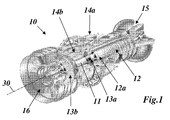
- FIG. 1 shows a perspective, partially sectioned view of an example of such a gas turbine, which is offered by the Applicant and is known under the type designation GT26 ® .
- the gas turbine 10 of Fig. 1 is equipped with a so-called sequential combustion. It comprises a multi-stage compressor 12, which draws and compresses air via an air inlet 15. The compressed air is used in a subsequent first annular combustion chamber 14a partially for the combustion of a injected fuel. The resulting hot gas flows through a first turbine 13a and then enters a second combustion chamber 14b, where the remaining air is used to burn a re-injected fuel. The hot gas stream coming from the second combustion chamber 14b is expanded under operating power in a second turbine 13b and exits the gas turbine 10 through an exhaust gas outlet 16 to be discharged to the outside or used to generate steam in a combined cycle power plant.
- the compressor 12 and the two turbines 13a, 13b have sets of blades rotating about the axis 30 which, together with stator vanes secured to the surrounding stator, form the blading of the machine. All blades are arranged on a common, rotatable about the axis of the rotor 11 and releasably secured to the rotor shaft by means provided therefor rotor grooves. Particular attention is paid to the last stages 12a of the compressor 12, in which the compressed air reaches temperatures of several hundred degrees Celsius.
- An increase in power of the gas turbine is associated with an increase in mass flow through the compressor resulting in a higher gas temperature in the last compressor stages 12a.
- the contemporary, advanced aerodynamic design of the blades of the compressor requires greater axial chord lengths, resulting in a greater distance between the rotor grooves 19.
- a rotor groove formed in this way has at its bottom a reduced bottom section 23 with a continuously curved cross-sectional contour, which is characterized by a large radius of curvature in the region of the median plane 33 and is mirror-symmetrical to the median plane 33 for reducing thermal stresses.
- the object is solved by the entirety of the features of claims 1 and 8.
- the basic idea of the invention is that the rotor groove at its bottom for reducing thermal stresses in a conventional manner has an extended in the axial and radial directions bottom area with a continuously curved cross-sectional contour, and the blade root of the blades is adapted in the radial direction to the extended bottom area ,
- the widened floor area is mirror-symmetrical to a central plane passing through the rotor groove and perpendicular to the axis, and the radius of curvature of the cross-sectional contour of the floor area decreases starting from the median plane towards the edge.
- Another embodiment of the invention is characterized in that the extended bottom portion in the axial direction has a predetermined maximum width, that the radial abutment surfaces in the axial direction have a predetermined minimum distance, and that the ratio of minimum distance to maximum width between 0.1 and 0.6, ie 0.1 ⁇ d 5 / d 1 ⁇ 0.6.
- the extended bottom region has a predetermined first maximum depth relative to the radial abutment surfaces
- the extended bottom region has a predetermined second maximum depth relative to the inner edges of the axial abutment surfaces
- the ratio of second maximum depth to first maximum Depth is between 0.4 and 0.9, ie 0.4 ⁇ d 3 / d 4 ⁇ 0.9.
- the blade root is extended below the hammer head for bridging the radial extension of the extended bottom region in the radial direction.
- an extension bolt extending in the radial direction is provided for extending the blade root.
- the comparatively Slim extension studs bridge the gap without adding bulk to the bucket.
- extension bolt is formed on the hammer head.
- a curved transition surface is provided at the transition between the extension bolt and the hammer head to ensure a steady transition.
- extension bolt as a separate part and to connect this with the hammer head.
- the mass of the blade can be further reduced if mass-reducing recesses are provided in the blade root.
- the recesses extend over the hammer head and the extension bolt.
- these recesses may extend in other, for example, radial direction.
- An embodiment of the rotor according to the invention is characterized in that between the lower end of the extension bolt and the bottom of the extended bottom portion, a gap remains free, and that in the free space, a spring is arranged, which the blade with the blade root in the radial direction against presses the radial abutment surfaces.
- Another embodiment is characterized in that the hammer head has a predetermined height, that the extension bolt has a predetermined radial length, and that the height to length ratio is between 0.2 and 0.8, ie 0.2 ⁇ d 2 / d 1 ⁇ 0.8.
- a further embodiment is characterized in that the hammer head has a predetermined first axial width, that the extension bolt has a predetermined second axial width, and that the ratio of the second to the first axial width is between 0.2 and 0.6, ie 0 , 2 ⁇ d 4 / d 3 ⁇ 0.6.
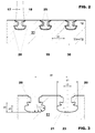
- Fig. 4 shows that too Fig. 2 comparable longitudinal section through the rotor 11 of a gas turbine in the region of the last stages of the compressor according to the invention.
- a comparison of Fig. 2 and 4 shows that the upper portion of the rotor groove 21 with respect to the known Rotornutgeometrie from Fig. 2 remains unchanged. Accordingly, the radial and axial abutment surfaces 25 and 20 remain virtually unchanged. Thus, the proven design can be used in this area.
- the widened floor area 23 of the rotor groove 21 is characterized in that the cross-sectional contour of the floor area 23 is continuously curved, and that the radius of curvature of the cross-sectional contour of the floor area 23 is very large in the area of the median plane and starts from the median plane decreases sharply towards the edge.
- the cross-sectional contour is mirror-symmetrical to the median plane.
- the extended bottom portion 23 extends immediately below the axial abutment surfaces 20 on both sides in the axial direction in the manner of an undercut. He shows how Fig. 3 shows, in the axial direction, a predetermined maximum width d 1 , while the radial stop surfaces 25 in the axial direction a given minimum distance d 5 have. It is particularly favorable if the ratio of minimum distance d 5 to maximum width d 1 is between 0.1 and 0.6, ie if the inequality 0.1 ⁇ d 5 / d 1 ⁇ 0.6 applies.
- the extended bottom portion 23 has a predetermined first maximum depth d 4 .
- the extended bottom portion 23 has a predetermined second maximum depth d 3 . It is particularly favorable if the ratio of the second maximum depth d 3 to the first maximum depth d 4 is between 0.4 and 0.9, ie if the inequality 0.4 ⁇ d 3 / d 4 ⁇ 0.9 applies.
- Another inequality relates to the offset of the rotor grooves to each other. If a plurality of similar rotor slots 21 are provided offset from each other by a predetermined distance d 2 in the axial direction, it is advantageous if the ratio of maximum width d 1 to distance d 2 is between 0.5 and 0.8, ie the inequality 0 , 5 ⁇ d 1 / d 2 ⁇ 0.8.
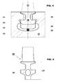
- the blade 26 of the Fig. 5 and 6 has a blade root 27, which is formed in the upper portion, which extends to the axial abutment surfaces, substantially the same as the blade root 18 from Fig. 2 ,
- the hammer head 32 attached radial extension downwards by means of an integrally formed on the hammer head 32 extension bolt 29, which is narrower (width d 4 ) than the hammer head 32 (width d 3 ).
- the radial length (d 1 ) of the Extension bolt 29 is significantly larger than the height (d 2 ) of the hammer head 32nd
- a curved transition surface 28 is preferably provided at the transition between the extension bolt 29 and the hammer head 32 to ensure a steady transition.
- the extension pin 29 As a cost-effective alternative for the axial extension of the blade root 18, it is advisable to form the extension pin 29 as a separate part and to connect that with the hammer head 32. As the requirements of practical operation sufficient connection method have thereby screwing or welding proven.
- the hammer head 32 may be provided at the bottom 34 in the region of the median plane 33 with a threaded bore 35. With the help of an integrally formed threaded bolt 36 of the extension bolt 29 is screwed into the blade root 18, as in Fig. 7 outlined as an example.
- one or more mass-reducing recesses 31 are provided in the blade root 18, 27, which can be designed as a circular, elliptical or otherwise shaped hole or slot in a single or multiple design.
- the recess (s) 31 extend or extend in the radial direction, preferably via the hammer head 32 and the extension bolt 29. In this case, this recess (s) 31 extends or runs preferably, but not necessarily, in the circumferential direction, as in FIG Fig. 5 . 6 and 7 shown.
- other suitable directional curves and embodiments of mass-reducing recesses 31 are likewise conceivable, for example in the form of bores introduced radially into the blade root 27.
- the ratio of height (d 2 ) of the hammer head 32 to length (d 1 ) of the extension bolt 29 is preferably between 0.2 and 0.8, ie the inequality 0.2 ⁇ d 2 / d 1 ⁇ 0.8 applies.
- the ratio of the axial width (d 4 ) of the extension bolt 29 to the axial width (d 3 ) of the hammer head 32 is preferably between 0.2 and 0.6, ie, the inequality 0.2 ⁇ d 4 / d 3 ⁇ 0, 6th
Landscapes
- Engineering & Computer Science (AREA)
- Mechanical Engineering (AREA)
- General Engineering & Computer Science (AREA)
- Structures Of Non-Positive Displacement Pumps (AREA)
- Turbine Rotor Nozzle Sealing (AREA)
Applications Claiming Priority (2)
| Application Number | Priority Date | Filing Date | Title |
|---|---|---|---|
| CH01724/09A CH702204A1 (de) | 2009-11-10 | 2009-11-10 | Rotor für eine axial durchströmte turbomaschine sowie gasturbine für solchen rotor. |
| CH01723/09A CH702203A1 (de) | 2009-11-10 | 2009-11-10 | Rotor für eine axial durchströmte turbomaschine sowie laufschaufel für einen solchen rotor. |
Publications (2)
| Publication Number | Publication Date |
|---|---|
| EP2320030A1 true EP2320030A1 (fr) | 2011-05-11 |
| EP2320030B1 EP2320030B1 (fr) | 2012-12-19 |
Family
ID=43587536
Family Applications (1)
| Application Number | Title | Priority Date | Filing Date |
|---|---|---|---|
| EP10189854A Active EP2320030B1 (fr) | 2009-11-10 | 2010-11-03 | Rotor et aube de rotor pour une turbomachine axiale |
Country Status (4)
| Country | Link |
|---|---|
| US (1) | US8770938B2 (fr) |
| EP (1) | EP2320030B1 (fr) |
| JP (1) | JP5765918B2 (fr) |
| CN (1) | CN102121400B (fr) |
Cited By (4)
| Publication number | Priority date | Publication date | Assignee | Title |
|---|---|---|---|---|
| EP2873808A1 (fr) * | 2013-11-19 | 2015-05-20 | MTU Aero Engines GmbH | Composé aubes-disques, procédé et turbomachine |
| EP2956626B1 (fr) * | 2013-02-12 | 2019-11-20 | United Technologies Corporation | Aube de soufflante comprenant des cavités extérieures |
| US12110809B1 (en) | 2023-04-04 | 2024-10-08 | Ge Infrastructure Technology Llc | Turbine blade and assembly with dovetail arrangement for enlarged rotor groove |
| EP4442964A1 (fr) * | 2023-04-04 | 2024-10-09 | General Electric Technology GmbH | Procédé d'assemblage d'une aube de turbine dans une rainure de rotor définie dans un rotor ayant un axe |
Families Citing this family (11)
| Publication number | Priority date | Publication date | Assignee | Title |
|---|---|---|---|---|
| RU2476729C1 (ru) * | 2011-07-29 | 2013-02-27 | Открытое акционерное общество "Научно-производственное объединение "Сатурн" (ОАО "НПО "Сатурн") | Рабочее колесо осевого компрессора газотурбинного двигателя |
| JP5922370B2 (ja) | 2011-10-20 | 2016-05-24 | 三菱日立パワーシステムズ株式会社 | 動翼支持構造 |
| US9239062B2 (en) * | 2012-09-10 | 2016-01-19 | General Electric Company | Low radius ratio fan for a gas turbine engine |
| CN103850715A (zh) * | 2012-11-30 | 2014-06-11 | 西门子公司 | 转子轮盘 |
| RU2530198C1 (ru) * | 2013-02-28 | 2014-10-10 | Общество с ограниченной ответственностью "Владимирский инновационно-технологический центр" | Способ крепления лопастей к ступице колеса |
| RU168474U1 (ru) * | 2016-01-11 | 2017-02-06 | Владимир Семенович Мельников | Крепление лопасти динамической машины на укороченном хвостовике |
| US9682756B1 (en) * | 2016-10-17 | 2017-06-20 | General Electric Company | System for composite marine propellers |
| US11021972B2 (en) | 2018-08-14 | 2021-06-01 | Rolls-Royce North American Technologies Inc. | Variable pitch blade holder for gas turbine engine |
| CN112049686A (zh) * | 2019-06-05 | 2020-12-08 | 中国航发商用航空发动机有限责任公司 | 燃气轮机转子和燃气轮机 |
| CN114382552A (zh) * | 2022-02-24 | 2022-04-22 | 杭州汽轮机股份有限公司 | 一种超高转速大负荷工业透平动叶片及动叶片组 |
| US12055069B2 (en) * | 2022-09-20 | 2024-08-06 | Siemens Energy, Inc. | System and method for reducing blade hook stress in a turbine blade |
Citations (10)
| Publication number | Priority date | Publication date | Assignee | Title |
|---|---|---|---|---|
| GB614678A (en) * | 1946-07-19 | 1948-12-20 | Parsons C A & Co Ltd | Improvements in or relating to turbine blading or the like |
| GB674543A (en) * | 1949-05-25 | 1952-06-25 | Ag Fuer Technische Studien | Improvements in and relating to blade assemblies for turbines and rotary compressors |
| US4645425A (en) * | 1984-12-19 | 1987-02-24 | United Technologies Corporation | Turbine or compressor blade mounting |
| US5141401A (en) | 1990-09-27 | 1992-08-25 | General Electric Company | Stress-relieved rotor blade attachment slot |
| EP0707135A2 (fr) * | 1994-10-14 | 1996-04-17 | ABB Management AG | Rotor avec aubes |
| EP1130217A1 (fr) * | 2000-03-01 | 2001-09-05 | ABB Alstom Power N.V. | Fixation des aubes dans une turbomachine |
| EP1253293A2 (fr) * | 2001-04-26 | 2002-10-30 | ALSTOM (Switzerland) Ltd | Fixation d'une aube rotorique au rotor d'une turbomachine |
| WO2005054682A1 (fr) | 2003-12-06 | 2005-06-16 | Alstom Technology Ltd | Rotor pour un compresseur |
| JP2005220825A (ja) * | 2004-02-06 | 2005-08-18 | Mitsubishi Heavy Ind Ltd | タービン動翼 |
| EP1703080A1 (fr) | 2005-03-03 | 2006-09-20 | ALSTOM Technology Ltd | Machine tournante |
Family Cites Families (18)
| Publication number | Priority date | Publication date | Assignee | Title |
|---|---|---|---|---|
| US2809801A (en) * | 1952-04-18 | 1957-10-15 | Ingersoll Rand Co | Turbine rotor construction |
| US3584971A (en) | 1969-05-28 | 1971-06-15 | Westinghouse Electric Corp | Bladed rotor structure for a turbine or a compressor |
| DE2242448A1 (de) * | 1972-08-29 | 1974-03-07 | Motoren Turbinen Union | Laufrad fuer stroemungsmaschine |
| US5018271A (en) * | 1988-09-09 | 1991-05-28 | Airfoil Textron Inc. | Method of making a composite blade with divergent root |
| US5282720A (en) * | 1992-09-15 | 1994-02-01 | General Electric Company | Fan blade retainer |
| US5431542A (en) * | 1994-04-29 | 1995-07-11 | United Technologies Corporation | Ramped dovetail rails for rotor blade assembly |
| US6102664A (en) * | 1995-12-14 | 2000-08-15 | The United States Of America As Represented By The Administrator Of The National Aeronautics And Space Administration | Blading system and method for controlling structural vibrations |
| US6183202B1 (en) * | 1999-04-30 | 2001-02-06 | General Electric Company | Stress relieved blade support |
| ITMI20011970A1 (it) * | 2001-09-21 | 2003-03-21 | Nuovo Pignone Spa | Connessione migliorata di palette su di un disco rotorico di una turbina a gas |
| US6773234B2 (en) * | 2002-10-18 | 2004-08-10 | General Electric Company | Methods and apparatus for facilitating preventing failure of gas turbine engine blades |
| CN1497131A (zh) * | 2002-10-18 | 2004-05-19 | 通用电气公司 | 有利于防止燃气涡轮发动机的叶片损坏的方法和装置 |
| US6761538B2 (en) * | 2002-10-31 | 2004-07-13 | General Electric Company | Continual radial loading device for steam turbine reaction type buckets and related method |
| DE10346239A1 (de) * | 2003-10-06 | 2005-04-21 | Alstom Technology Ltd Baden | Verfahren zur Fixierung für die Beschaufelung einer Strömungsmaschine und Fixiervorrichtung |
| JP2007231868A (ja) * | 2006-03-02 | 2007-09-13 | Hitachi Ltd | 蒸気タービン動翼およびそれを用いた蒸気タービン並びに蒸気タービン発電プラント |
| GB2442968B (en) * | 2006-10-20 | 2009-08-19 | Rolls Royce Plc | A turbomachine rotor blade and a turbomachine rotor |
| US8047797B2 (en) * | 2007-07-16 | 2011-11-01 | Nuovo Pignone Holdings, S.P.A. | Steam turbine and rotating blade |
| EP2045444B1 (fr) | 2007-10-01 | 2015-11-18 | Alstom Technology Ltd | Aube de rotor, procédé de fabrication d'une aube de rotor, et compresseur avec une telle aube |
| US20090285690A1 (en) * | 2008-05-19 | 2009-11-19 | Brown Clayton D | Axial blade slot pressure face with undercut |
-
2010
- 2010-11-03 EP EP10189854A patent/EP2320030B1/fr active Active
- 2010-11-09 US US12/942,565 patent/US8770938B2/en not_active Expired - Fee Related
- 2010-11-10 CN CN201010624485.3A patent/CN102121400B/zh active Active
- 2010-11-10 JP JP2010251639A patent/JP5765918B2/ja not_active Expired - Fee Related
Patent Citations (10)
| Publication number | Priority date | Publication date | Assignee | Title |
|---|---|---|---|---|
| GB614678A (en) * | 1946-07-19 | 1948-12-20 | Parsons C A & Co Ltd | Improvements in or relating to turbine blading or the like |
| GB674543A (en) * | 1949-05-25 | 1952-06-25 | Ag Fuer Technische Studien | Improvements in and relating to blade assemblies for turbines and rotary compressors |
| US4645425A (en) * | 1984-12-19 | 1987-02-24 | United Technologies Corporation | Turbine or compressor blade mounting |
| US5141401A (en) | 1990-09-27 | 1992-08-25 | General Electric Company | Stress-relieved rotor blade attachment slot |
| EP0707135A2 (fr) * | 1994-10-14 | 1996-04-17 | ABB Management AG | Rotor avec aubes |
| EP1130217A1 (fr) * | 2000-03-01 | 2001-09-05 | ABB Alstom Power N.V. | Fixation des aubes dans une turbomachine |
| EP1253293A2 (fr) * | 2001-04-26 | 2002-10-30 | ALSTOM (Switzerland) Ltd | Fixation d'une aube rotorique au rotor d'une turbomachine |
| WO2005054682A1 (fr) | 2003-12-06 | 2005-06-16 | Alstom Technology Ltd | Rotor pour un compresseur |
| JP2005220825A (ja) * | 2004-02-06 | 2005-08-18 | Mitsubishi Heavy Ind Ltd | タービン動翼 |
| EP1703080A1 (fr) | 2005-03-03 | 2006-09-20 | ALSTOM Technology Ltd | Machine tournante |
Cited By (7)
| Publication number | Priority date | Publication date | Assignee | Title |
|---|---|---|---|---|
| EP2956626B1 (fr) * | 2013-02-12 | 2019-11-20 | United Technologies Corporation | Aube de soufflante comprenant des cavités extérieures |
| EP2873808A1 (fr) * | 2013-11-19 | 2015-05-20 | MTU Aero Engines GmbH | Composé aubes-disques, procédé et turbomachine |
| US10041363B2 (en) | 2013-11-19 | 2018-08-07 | MTU Aero Engines AG | Blade-disk assembly, method and turbomachine |
| US12110809B1 (en) | 2023-04-04 | 2024-10-08 | Ge Infrastructure Technology Llc | Turbine blade and assembly with dovetail arrangement for enlarged rotor groove |
| EP4442963A1 (fr) * | 2023-04-04 | 2024-10-09 | General Electric Technology GmbH | Aube de turbine et agencement d'aube de turbine pour une rainure de rotor définie dans un rotor ayant un axe et systèmes de turbine |
| EP4442964A1 (fr) * | 2023-04-04 | 2024-10-09 | General Electric Technology GmbH | Procédé d'assemblage d'une aube de turbine dans une rainure de rotor définie dans un rotor ayant un axe |
| US12435637B2 (en) | 2023-04-04 | 2025-10-07 | Ge Infrastructure Technology Llc | Method for turbine blade and assembly with dovetail arrangement for enlarged rotor groove |
Also Published As
| Publication number | Publication date |
|---|---|
| US8770938B2 (en) | 2014-07-08 |
| CN102121400A (zh) | 2011-07-13 |
| JP2011102586A (ja) | 2011-05-26 |
| CN102121400B (zh) | 2015-12-16 |
| US20110110785A1 (en) | 2011-05-12 |
| JP5765918B2 (ja) | 2015-08-19 |
| EP2320030B1 (fr) | 2012-12-19 |
Similar Documents
| Publication | Publication Date | Title |
|---|---|---|
| EP2320030B1 (fr) | Rotor et aube de rotor pour une turbomachine axiale | |
| EP2024606B1 (fr) | Conduit d'écoulement annulaire pour une turbomachine pouvant être traversée par un courant principal dans le sens axial | |
| EP2194232B1 (fr) | Turbomachine dotée d'une barrière à couche frontière sur la paroi latérale | |
| EP1907671B1 (fr) | Couronne d'aubes de turbine a gaz | |
| EP2249044B1 (fr) | Compresseur ou pompe avec extraction de fluide | |
| EP0916812B1 (fr) | Etage final pour turbine axial | |
| EP1898054B1 (fr) | Turbine a gaz | |
| DE60206129T2 (de) | Turbinenschaufel mit einer Abwärtsstufe in der Plattform, sowie entsprechende Turbine | |
| EP2226509B1 (fr) | Turbo compresseur ou pompe avec injection de fluide pour influencer la couche limite | |
| DE102007025006A1 (de) | Doppelwellen-Gasturbine | |
| EP3176370B1 (fr) | Ensemble d'aubes directrices pour turbomachine | |
| DE102016124296B4 (de) | Innere Kühlkonfigurationen in Turbinenlaufschaufeln | |
| DE102016125091A1 (de) | Turbinenlaufschaufeln mit Spitzendeckband | |
| DE102008002950A1 (de) | Dampfturbinenlaufschaufel | |
| DE102019120816B3 (de) | Verdichterlaufrad mit geteilten Hauptschaufeln | |
| CH709266B1 (de) | Turbinenschaufel und Verfahren zum Auswuchten eines Spitzendeckbandes einer Turbinenschaufel und Gasturbine. | |
| EP1675702B1 (fr) | Turbine à gaz et aube mobile de turbomachine | |
| DE102007050916A1 (de) | Verfahren und Vorrichtung zum Zusammenbau von Gasturbinen-Triebwerken | |
| WO2003054356A1 (fr) | Piece a sollicitation thermique | |
| DE112016000685B4 (de) | Turbine und gasturbine | |
| DE102019135335A1 (de) | Hybrid-laufschaufeln für turbinentriebwerke | |
| CH701310B1 (de) | Turbinentriebwerk mit Schaufelbefestigungselement mit erstem Schwalbenschwanzschlitz, dessen Länge grösser ist als die eines zweiten Schwalbenschwanzschlitzes. | |
| CH702203A1 (de) | Rotor für eine axial durchströmte turbomaschine sowie laufschaufel für einen solchen rotor. | |
| CH707844B1 (de) | Turbinenschaufel mit Kühlkanälen für eine Gasturbine. | |
| DE2532554C2 (de) | Verdichterstator |
Legal Events
| Date | Code | Title | Description |
|---|---|---|---|
| PUAI | Public reference made under article 153(3) epc to a published international application that has entered the european phase |
Free format text: ORIGINAL CODE: 0009012 |
|
| AK | Designated contracting states |
Kind code of ref document: A1 Designated state(s): AL AT BE BG CH CY CZ DE DK EE ES FI FR GB GR HR HU IE IS IT LI LT LU LV MC MK MT NL NO PL PT RO RS SE SI SK SM TR |
|
| AX | Request for extension of the european patent |
Extension state: BA ME |
|
| 17P | Request for examination filed |
Effective date: 20111111 |
|
| RIC1 | Information provided on ipc code assigned before grant |
Ipc: F01D 5/30 20060101AFI20120209BHEP |
|
| GRAP | Despatch of communication of intention to grant a patent |
Free format text: ORIGINAL CODE: EPIDOSNIGR1 |
|
| GRAS | Grant fee paid |
Free format text: ORIGINAL CODE: EPIDOSNIGR3 |
|
| GRAL | Information related to payment of fee for publishing/printing deleted |
Free format text: ORIGINAL CODE: EPIDOSDIGR3 |
|
| GRAS | Grant fee paid |
Free format text: ORIGINAL CODE: EPIDOSNIGR3 |
|
| GRAA | (expected) grant |
Free format text: ORIGINAL CODE: 0009210 |
|
| AK | Designated contracting states |
Kind code of ref document: B1 Designated state(s): AL AT BE BG CH CY CZ DE DK EE ES FI FR GB GR HR HU IE IS IT LI LT LU LV MC MK MT NL NO PL PT RO RS SE SI SK SM TR |
|
| REG | Reference to a national code |
Ref country code: GB Ref legal event code: FG4D Free format text: NOT ENGLISH |
|
| REG | Reference to a national code |
Ref country code: CH Ref legal event code: EP |
|
| REG | Reference to a national code |
Ref country code: AT Ref legal event code: REF Ref document number: 589535 Country of ref document: AT Kind code of ref document: T Effective date: 20130115 |
|
| REG | Reference to a national code |
Ref country code: DE Ref legal event code: R096 Ref document number: 502010001898 Country of ref document: DE Effective date: 20130214 |
|
| PG25 | Lapsed in a contracting state [announced via postgrant information from national office to epo] |
Ref country code: FI Free format text: LAPSE BECAUSE OF FAILURE TO SUBMIT A TRANSLATION OF THE DESCRIPTION OR TO PAY THE FEE WITHIN THE PRESCRIBED TIME-LIMIT Effective date: 20121219 Ref country code: LT Free format text: LAPSE BECAUSE OF FAILURE TO SUBMIT A TRANSLATION OF THE DESCRIPTION OR TO PAY THE FEE WITHIN THE PRESCRIBED TIME-LIMIT Effective date: 20121219 Ref country code: ES Free format text: LAPSE BECAUSE OF FAILURE TO SUBMIT A TRANSLATION OF THE DESCRIPTION OR TO PAY THE FEE WITHIN THE PRESCRIBED TIME-LIMIT Effective date: 20130330 Ref country code: NO Free format text: LAPSE BECAUSE OF FAILURE TO SUBMIT A TRANSLATION OF THE DESCRIPTION OR TO PAY THE FEE WITHIN THE PRESCRIBED TIME-LIMIT Effective date: 20130319 Ref country code: SE Free format text: LAPSE BECAUSE OF FAILURE TO SUBMIT A TRANSLATION OF THE DESCRIPTION OR TO PAY THE FEE WITHIN THE PRESCRIBED TIME-LIMIT Effective date: 20121219 |
|
| REG | Reference to a national code |
Ref country code: NL Ref legal event code: VDEP Effective date: 20121219 |
|
| REG | Reference to a national code |
Ref country code: LT Ref legal event code: MG4D |
|
| PG25 | Lapsed in a contracting state [announced via postgrant information from national office to epo] |
Ref country code: LV Free format text: LAPSE BECAUSE OF FAILURE TO SUBMIT A TRANSLATION OF THE DESCRIPTION OR TO PAY THE FEE WITHIN THE PRESCRIBED TIME-LIMIT Effective date: 20121219 Ref country code: SI Free format text: LAPSE BECAUSE OF FAILURE TO SUBMIT A TRANSLATION OF THE DESCRIPTION OR TO PAY THE FEE WITHIN THE PRESCRIBED TIME-LIMIT Effective date: 20121219 Ref country code: GR Free format text: LAPSE BECAUSE OF FAILURE TO SUBMIT A TRANSLATION OF THE DESCRIPTION OR TO PAY THE FEE WITHIN THE PRESCRIBED TIME-LIMIT Effective date: 20130320 |
|
| PG25 | Lapsed in a contracting state [announced via postgrant information from national office to epo] |
Ref country code: SK Free format text: LAPSE BECAUSE OF FAILURE TO SUBMIT A TRANSLATION OF THE DESCRIPTION OR TO PAY THE FEE WITHIN THE PRESCRIBED TIME-LIMIT Effective date: 20121219 Ref country code: IS Free format text: LAPSE BECAUSE OF FAILURE TO SUBMIT A TRANSLATION OF THE DESCRIPTION OR TO PAY THE FEE WITHIN THE PRESCRIBED TIME-LIMIT Effective date: 20130419 Ref country code: BG Free format text: LAPSE BECAUSE OF FAILURE TO SUBMIT A TRANSLATION OF THE DESCRIPTION OR TO PAY THE FEE WITHIN THE PRESCRIBED TIME-LIMIT Effective date: 20130319 Ref country code: RS Free format text: LAPSE BECAUSE OF FAILURE TO SUBMIT A TRANSLATION OF THE DESCRIPTION OR TO PAY THE FEE WITHIN THE PRESCRIBED TIME-LIMIT Effective date: 20121219 Ref country code: EE Free format text: LAPSE BECAUSE OF FAILURE TO SUBMIT A TRANSLATION OF THE DESCRIPTION OR TO PAY THE FEE WITHIN THE PRESCRIBED TIME-LIMIT Effective date: 20121219 Ref country code: CZ Free format text: LAPSE BECAUSE OF FAILURE TO SUBMIT A TRANSLATION OF THE DESCRIPTION OR TO PAY THE FEE WITHIN THE PRESCRIBED TIME-LIMIT Effective date: 20121219 |
|
| PG25 | Lapsed in a contracting state [announced via postgrant information from national office to epo] |
Ref country code: NL Free format text: LAPSE BECAUSE OF FAILURE TO SUBMIT A TRANSLATION OF THE DESCRIPTION OR TO PAY THE FEE WITHIN THE PRESCRIBED TIME-LIMIT Effective date: 20121219 Ref country code: PT Free format text: LAPSE BECAUSE OF FAILURE TO SUBMIT A TRANSLATION OF THE DESCRIPTION OR TO PAY THE FEE WITHIN THE PRESCRIBED TIME-LIMIT Effective date: 20130419 Ref country code: RO Free format text: LAPSE BECAUSE OF FAILURE TO SUBMIT A TRANSLATION OF THE DESCRIPTION OR TO PAY THE FEE WITHIN THE PRESCRIBED TIME-LIMIT Effective date: 20121219 Ref country code: PL Free format text: LAPSE BECAUSE OF FAILURE TO SUBMIT A TRANSLATION OF THE DESCRIPTION OR TO PAY THE FEE WITHIN THE PRESCRIBED TIME-LIMIT Effective date: 20121219 |
|
| PLBE | No opposition filed within time limit |
Free format text: ORIGINAL CODE: 0009261 |
|
| STAA | Information on the status of an ep patent application or granted ep patent |
Free format text: STATUS: NO OPPOSITION FILED WITHIN TIME LIMIT |
|
| PG25 | Lapsed in a contracting state [announced via postgrant information from national office to epo] |
Ref country code: DK Free format text: LAPSE BECAUSE OF FAILURE TO SUBMIT A TRANSLATION OF THE DESCRIPTION OR TO PAY THE FEE WITHIN THE PRESCRIBED TIME-LIMIT Effective date: 20121219 |
|
| 26N | No opposition filed |
Effective date: 20130920 |
|
| PG25 | Lapsed in a contracting state [announced via postgrant information from national office to epo] |
Ref country code: CY Free format text: LAPSE BECAUSE OF FAILURE TO SUBMIT A TRANSLATION OF THE DESCRIPTION OR TO PAY THE FEE WITHIN THE PRESCRIBED TIME-LIMIT Effective date: 20121219 Ref country code: HR Free format text: LAPSE BECAUSE OF FAILURE TO SUBMIT A TRANSLATION OF THE DESCRIPTION OR TO PAY THE FEE WITHIN THE PRESCRIBED TIME-LIMIT Effective date: 20121219 |
|
| PG25 | Lapsed in a contracting state [announced via postgrant information from national office to epo] |
Ref country code: IT Free format text: LAPSE BECAUSE OF FAILURE TO SUBMIT A TRANSLATION OF THE DESCRIPTION OR TO PAY THE FEE WITHIN THE PRESCRIBED TIME-LIMIT Effective date: 20121219 |
|
| REG | Reference to a national code |
Ref country code: DE Ref legal event code: R097 Ref document number: 502010001898 Country of ref document: DE Effective date: 20130920 |
|
| BERE | Be: lapsed |
Owner name: ALSTOM TECHNOLOGY LTD Effective date: 20131130 |
|
| PG25 | Lapsed in a contracting state [announced via postgrant information from national office to epo] |
Ref country code: MC Free format text: LAPSE BECAUSE OF FAILURE TO SUBMIT A TRANSLATION OF THE DESCRIPTION OR TO PAY THE FEE WITHIN THE PRESCRIBED TIME-LIMIT Effective date: 20121219 |
|
| REG | Reference to a national code |
Ref country code: IE Ref legal event code: MM4A |
|
| PG25 | Lapsed in a contracting state [announced via postgrant information from national office to epo] |
Ref country code: BE Free format text: LAPSE BECAUSE OF NON-PAYMENT OF DUE FEES Effective date: 20131130 |
|
| PG25 | Lapsed in a contracting state [announced via postgrant information from national office to epo] |
Ref country code: IE Free format text: LAPSE BECAUSE OF NON-PAYMENT OF DUE FEES Effective date: 20131103 |
|
| PG25 | Lapsed in a contracting state [announced via postgrant information from national office to epo] |
Ref country code: SM Free format text: LAPSE BECAUSE OF FAILURE TO SUBMIT A TRANSLATION OF THE DESCRIPTION OR TO PAY THE FEE WITHIN THE PRESCRIBED TIME-LIMIT Effective date: 20121219 |
|
| PG25 | Lapsed in a contracting state [announced via postgrant information from national office to epo] |
Ref country code: TR Free format text: LAPSE BECAUSE OF FAILURE TO SUBMIT A TRANSLATION OF THE DESCRIPTION OR TO PAY THE FEE WITHIN THE PRESCRIBED TIME-LIMIT Effective date: 20121219 |
|
| REG | Reference to a national code |
Ref country code: CH Ref legal event code: PL |
|
| PG25 | Lapsed in a contracting state [announced via postgrant information from national office to epo] |
Ref country code: HU Free format text: LAPSE BECAUSE OF FAILURE TO SUBMIT A TRANSLATION OF THE DESCRIPTION OR TO PAY THE FEE WITHIN THE PRESCRIBED TIME-LIMIT; INVALID AB INITIO Effective date: 20101103 Ref country code: LU Free format text: LAPSE BECAUSE OF NON-PAYMENT OF DUE FEES Effective date: 20131103 Ref country code: LI Free format text: LAPSE BECAUSE OF NON-PAYMENT OF DUE FEES Effective date: 20141130 Ref country code: MK Free format text: LAPSE BECAUSE OF FAILURE TO SUBMIT A TRANSLATION OF THE DESCRIPTION OR TO PAY THE FEE WITHIN THE PRESCRIBED TIME-LIMIT Effective date: 20121219 Ref country code: CH Free format text: LAPSE BECAUSE OF NON-PAYMENT OF DUE FEES Effective date: 20141130 |
|
| PG25 | Lapsed in a contracting state [announced via postgrant information from national office to epo] |
Ref country code: MT Free format text: LAPSE BECAUSE OF FAILURE TO SUBMIT A TRANSLATION OF THE DESCRIPTION OR TO PAY THE FEE WITHIN THE PRESCRIBED TIME-LIMIT Effective date: 20121219 |
|
| REG | Reference to a national code |
Ref country code: FR Ref legal event code: PLFP Year of fee payment: 6 |
|
| REG | Reference to a national code |
Ref country code: DE Ref legal event code: R081 Ref document number: 502010001898 Country of ref document: DE Owner name: GENERAL ELECTRIC TECHNOLOGY GMBH, CH Free format text: FORMER OWNER: ALSTOM TECHNOLOGY LTD., BADEN, CH Ref country code: DE Ref legal event code: R081 Ref document number: 502010001898 Country of ref document: DE Owner name: ANSALDO ENERGIA IP UK LIMITED, GB Free format text: FORMER OWNER: ALSTOM TECHNOLOGY LTD., BADEN, CH |
|
| REG | Reference to a national code |
Ref country code: FR Ref legal event code: PLFP Year of fee payment: 7 |
|
| REG | Reference to a national code |
Ref country code: FR Ref legal event code: CD Owner name: ALSTOM TECHNOLOGY LTD, CH Effective date: 20161110 |
|
| REG | Reference to a national code |
Ref country code: AT Ref legal event code: MM01 Ref document number: 589535 Country of ref document: AT Kind code of ref document: T Effective date: 20151103 |
|
| PG25 | Lapsed in a contracting state [announced via postgrant information from national office to epo] |
Ref country code: AT Free format text: LAPSE BECAUSE OF NON-PAYMENT OF DUE FEES Effective date: 20151103 |
|
| REG | Reference to a national code |
Ref country code: DE Ref legal event code: R081 Ref document number: 502010001898 Country of ref document: DE Owner name: ANSALDO ENERGIA IP UK LIMITED, GB Free format text: FORMER OWNER: GENERAL ELECTRIC TECHNOLOGY GMBH, BADEN, CH |
|
| REG | Reference to a national code |
Ref country code: GB Ref legal event code: 732E Free format text: REGISTERED BETWEEN 20170824 AND 20170830 |
|
| REG | Reference to a national code |
Ref country code: FR Ref legal event code: PLFP Year of fee payment: 8 |
|
| REG | Reference to a national code |
Ref country code: FR Ref legal event code: TP Owner name: ANSALDO ENERGIA IP UK LIMITED, GB Effective date: 20171221 |
|
| PGFP | Annual fee paid to national office [announced via postgrant information from national office to epo] |
Ref country code: FR Payment date: 20171121 Year of fee payment: 8 |
|
| PGFP | Annual fee paid to national office [announced via postgrant information from national office to epo] |
Ref country code: GB Payment date: 20171123 Year of fee payment: 8 |
|
| PG25 | Lapsed in a contracting state [announced via postgrant information from national office to epo] |
Ref country code: AL Free format text: LAPSE BECAUSE OF FAILURE TO SUBMIT A TRANSLATION OF THE DESCRIPTION OR TO PAY THE FEE WITHIN THE PRESCRIBED TIME-LIMIT Effective date: 20121219 |
|
| GBPC | Gb: european patent ceased through non-payment of renewal fee |
Effective date: 20181103 |
|
| PG25 | Lapsed in a contracting state [announced via postgrant information from national office to epo] |
Ref country code: FR Free format text: LAPSE BECAUSE OF NON-PAYMENT OF DUE FEES Effective date: 20181130 |
|
| PG25 | Lapsed in a contracting state [announced via postgrant information from national office to epo] |
Ref country code: GB Free format text: LAPSE BECAUSE OF NON-PAYMENT OF DUE FEES Effective date: 20181103 |
|
| P01 | Opt-out of the competence of the unified patent court (upc) registered |
Effective date: 20240430 |
|
| PGFP | Annual fee paid to national office [announced via postgrant information from national office to epo] |
Ref country code: DE Payment date: 20251118 Year of fee payment: 16 |