EP2321084B1 - Système et procédé pour une commande d'écoulement aérodynamique - Google Patents
Système et procédé pour une commande d'écoulement aérodynamique Download PDFInfo
- Publication number
- EP2321084B1 EP2321084B1 EP09803664.3A EP09803664A EP2321084B1 EP 2321084 B1 EP2321084 B1 EP 2321084B1 EP 09803664 A EP09803664 A EP 09803664A EP 2321084 B1 EP2321084 B1 EP 2321084B1
- Authority
- EP
- European Patent Office
- Prior art keywords
- electrode
- airflow
- voltage
- electrodes
- wing
- Prior art date
- Legal status (The legal status is an assumption and is not a legal conclusion. Google has not performed a legal analysis and makes no representation as to the accuracy of the status listed.)
- Active
Links
Images
Classifications
-
- B—PERFORMING OPERATIONS; TRANSPORTING
- B64—AIRCRAFT; AVIATION; COSMONAUTICS
- B64C—AEROPLANES; HELICOPTERS
- B64C23/00—Influencing air flow over aircraft surfaces, not otherwise provided for
- B64C23/005—Influencing air flow over aircraft surfaces, not otherwise provided for by other means not covered by groups B64C23/02 - B64C23/08, e.g. by electric charges, magnetic panels, piezoelectric elements, static charges or ultrasounds
-
- F—MECHANICAL ENGINEERING; LIGHTING; HEATING; WEAPONS; BLASTING
- F15—FLUID-PRESSURE ACTUATORS; HYDRAULICS OR PNEUMATICS IN GENERAL
- F15D—FLUID DYNAMICS, i.e. METHODS OR MEANS FOR INFLUENCING THE FLOW OF GASES OR LIQUIDS
- F15D1/00—Influencing flow of fluids
- F15D1/10—Influencing flow of fluids around bodies of solid material
- F15D1/12—Influencing flow of fluids around bodies of solid material by influencing the boundary layer
-
- B—PERFORMING OPERATIONS; TRANSPORTING
- B64—AIRCRAFT; AVIATION; COSMONAUTICS
- B64C—AEROPLANES; HELICOPTERS
- B64C2230/00—Boundary layer controls
- B64C2230/12—Boundary layer controls by using electromagnetic tiles, fluid ionizers, static charges or plasma
-
- Y—GENERAL TAGGING OF NEW TECHNOLOGICAL DEVELOPMENTS; GENERAL TAGGING OF CROSS-SECTIONAL TECHNOLOGIES SPANNING OVER SEVERAL SECTIONS OF THE IPC; TECHNICAL SUBJECTS COVERED BY FORMER USPC CROSS-REFERENCE ART COLLECTIONS [XRACs] AND DIGESTS
- Y02—TECHNOLOGIES OR APPLICATIONS FOR MITIGATION OR ADAPTATION AGAINST CLIMATE CHANGE
- Y02T—CLIMATE CHANGE MITIGATION TECHNOLOGIES RELATED TO TRANSPORTATION
- Y02T50/00—Aeronautics or air transport
- Y02T50/10—Drag reduction
Definitions
- the present application relates to vortex generators.
- the present application relates to vortex generators mounted to substantially continuous aerodynamic surfaces to energize boundary layer air to at least partially alleviate the onset of separated flow over the surfaces.
- streamwise vortex generators such as passive delta-shaped tabs
- SVGs streamwise vortex generators
- passive delta-shaped tabs can generate longitudinal vortices that can be effective in maintaining attached flow over a surface, such as the wing of an aircraft.
- the disadvantage of passive devices like these is that such passive devices are always deployed, even when not needed. Under such circumstances passive SVGs add parasitic drag that lowers the efficiency of air vehicles on which they are used.
- WO2007/133239 discloses a plasma actuator for an aircraft surface.
- the plasma actuator is configured to generate a plasma above the surface, the plasma coupling a directed momentum into the air surrounding the surface to reduce airflow separation from the surface.
- the plasma actuator comprises a first and second electrode. The first electrode is exposed, and the second is covered by a dielectric.
- a paraelectric gas flow accelerator is described in WO 99/35893 , in which a plasma panel comprising a substrate is configured with first and second sets of electrodes, where the second set of electrodes is positioned asymmetrically between the first set of electrodes.
- a RF voltage is applied to the electrodes sufficient to generate a discharge plasma in the gas adjacent to the substrate, the asymmetry in the electrode configuration results in force being applied to the active species in the plasma and in turn to the neutral background gas.
- the present invention can be used to accelerate or decelerate the gas, thereby increasing or decreasing aerodynamic drag or turbulence.
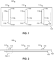
- FIG. 1 shows a plan view of a vortex generator system 100
- Figure 2 shows a front view of the vortex generator system 100
- the vortex generator system 100 comprises a plurality of plasma streamwise vortex generators (PSVGs) 110. While three PSVGs 110 are shown, alternative embodiments can include any number of PSVGs 110.
- PSVG 110 comprises a first electrode 115 and a second electrode 120 (shown in phantom in Figure 1 ).
- PSVG 110 also includes a dielectric layer 125 disposed between the first and second electrodes 115 and 120.
- electrodes 115 are shown as extending from the surface of dielectric layer 125, it should be appreciated that the electrodes 115 can be formed of a relatively thin material, and/or can be provided in respective recesses in the surface of dielectric layer 125 so as to be partially or completely flush with the upper surface of dielectric layer 125. In some embodiments, the electrodes 115 can be exposed to the surrounding air.
- the distance between neighboring adjacent first electrodes 115 can vary. In some embodiments, the distance between adjacent first electrodes 115 can be, for example in a range of three to four times the boundary layer thickness.
- the first and second electrodes 115 and 120 can be formed of electrically conductive material, for example copper or gold, which can be relatively thin, such as a copper foil or gold foil.
- the dielectric layer 125 can be formed of electrically insulating material, for example Kapton® polyimide film, a glass-ceramic such as MACOR®, or a thermoplastic such as Polyetheretherketone (PEEK). The thickness of the dielectric layer 125 is dependent on the maximum voltage that will be applied to the PSVG 110. It is contemplated that the dielectric layer 125 can include multiple layers of different material, including, for example, multiple types of dielectric materials. Also, while a single second electrode 120 is shown extending opposite multiple first electrodes 115, alternative embodiments can include multiple second electrodes 120 opposite single and/or multiple respective first electrodes 115.
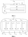
- each PSVG 110 includes a first electrode 115 and a second electrode 120 separated by a dielectric material 125.
- Figure 3 also includes a schematic view of an alternating current (AC) voltage source 130, a pressure sensor 150, and a controller 160.
- the AC voltage source 130 is connected between the first and second electrodes 115 and 120. While a single AC voltage source 130 is shown directly connected to the electrodes 115 and 120, actual implementations can include any number of AC voltage sources 130 and can further include additional circuitry as required between the AC voltage source 130 and the electrodes 115 and/or 120. For example, control circuitry may be added to allow for controlling the application of AC voltage to the electrodes 115 and 120.
- power conditioning circuitry may be desired, for example for damping voltage and/or current spikes.
- voltage and/or current shaping circuitry may be desired for adjusting various characteristics of the applied voltage and/or current, such as amplitude and frequency. It is also contemplated that a direct current (DC) voltage source could be used in place of the AC voltage source 130, and the DC voltage converted to AC voltage according to known methods.
- DC direct current
- a plan view shows a plurality of PSVGs 110 and a portion of a surface 135 that supports the PSVGs 110. While four PSVGs 110 are shown in Figure 4 , alternative embodiments can include any number of PSVGs 110. Note that the second electrode 120 is not shown in Figure 4 since it is obscured by the dielectric layer 125.
- the surface 135 can be, for example, a portion of an aerodynamic surface. For example, in applications related to aviation, the surface 135 can a portion of a surface of an airfoil, fuselage, tail boom, wing, rotor, rotating wing, nacelle, or any other surface that produces drag. Further applications in other industries, for example the automotive and rail industries, can also utilize the vortex generator system.
- the surface 135 is preferably unswept; for example, surface 135 can be a portion of an unswept wing of an aircraft.
- the surface 135 is arranged such that air typically flows in the airflow direction indicated by arrows FL.
- the surface 135 can be the upper surface of an aircraft wing where the aircraft is designed to fly in the direction indicated by arrow T, which results in the airflow direction indicated by arrows FL.
- the first electrodes 115 are somewhat rectangular, or at least have opposing lengthwise edges 115a and 115b that extend in a generally longitudinal direction that is at least somewhat parallel to the airflow direction indicated by arrows FL and the direction of travel indicated by arrow T.
- the widthwise edges 115c and 115d can be somewhat straight as shown, or can be more rounded.
- the PSVGs 110 it is desirable to arrange the PSVGs 110 such that their first electrodes 115 extend in a direction that is at least somewhat parallel to expected airflow.
- a first group of PSVGs 110 can be arranged such that the first electrodes 115 extend in a direction parallel to a first expected airflow direction
- a second group of PSVGs 110 can be arranged such that the first electrodes 115, or at least the lengthwise edges 115a and 115b, extend in a direction parallel to a second expected airflow direction, and so on for any number of groups of PSVGs 110 and respective airflow directions.
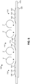
- FIG. 5 an enlarged view of Figure 2 is shown with the AC voltage source 130 activated.
- the AC voltage source 130 When the AC voltage source 130 is activated, a voltage differential is created between the first and second electrodes 115 and 120, causing the creation of plasma 140 along the longitudinal edges of the first electrodes 115.
- the AC voltage source 130 can be operated according to methods described in therein, for example, the AC voltage source 130 configured to apply voltage between the first and second electrodes 115 and 120 at a steady frequency or at an unsteady frequency.
- each first electrode 115 is oriented in the mean flow direction (indicated by arrow FL in Figure 4 ) in an arrangement that generates body forces in the cross-flow directions Fb as indicated in Figure 4 .
- the cross-flow oriented body force causes the flow downstream to roll up into single co-rotating, or pairs of counter-rotating, streamwise-oriented vortices as indicated by arrows V in Figure 5 .
- the vortices V are similar to those produced by passive SVGs.
- the PSVGs 110 can be operated only when needed.
- PSVGs 110 can be selectively activated by selective application of AC voltage to the first and second electrodes 115 and 120.
- PSVGs 110 can be made flush with the surface 135 so that they do not add parasitic drag.
- the PSVGs 110 can be optimally operated as flow conditions change, providing better efficiency in all applications.
- the PSVGs 110 can be automatically activated, adjusted, and/or otherwise controlled based on, for example, flight conditions and/or other detected conditions.
- pressure sensors 150 on the surface 135 (which, in some embodiments, can coincide with the upper surface of dielectric 125 as shown in Figure 3 ) can be used to detect airflow separation from the surface 135 and the PSVGs 110 can be automatically activated by controller 160 when undesirable flow separation occurs, and automatically deactivated by controller 160 when not needed, for example once correction of flow separation ceases to be necessary.
- the controller 160 can be any type of control system, computer, processing system, or the like, capable of receiving information from one or more pressure sensors 150 and controlling voltage to the PSVGs 110 based on the information received from the pressure sensors 150. It should be appreciated that, while the controller 160 is shown in schematic view in Figure 3 as controlling the voltage source 130 directly, in alternative embodiments, the controller 160 can control a switch, relay, or the like between the voltage source 130 and one or more of the PSVGs 110.
- the PSVGs 110 can be used, for example, to benefit the flow over the wings, wing fairings and fuselage of aircraft that are prone to flow separation.
- the PSVGs 110 disclosed herein include a first electrode 115, which can be an exposed electrode, overlaying a second electrode 120, which can be common to multiple PSVGs 110, and which is covered by a dielectric layer 125.
- the electrodes are oriented so that the actuator body force vectors, Fb, are in the cross-flow direction away from each side of a first electrode 115.
- Each of the body force components induces a cross-flow velocity that, in combination with the mean flow, produces streamwise-oriented counter-rotating vortices. Further downstream, these develop into a pair of streamwise vortices with counter-rotating circulation that is identical to that produced by conventional delta tabs.
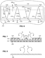
- FIG. 6 shows a plan view of the plasma vortex generator system 200.
- Figure 7 shows a cross-sectional view taken along section lines VII-VII in Figure 6.
- Figure 8 shows a second cross-sectional view taken downstream from the view in Figure 7 .
- the vortex generator system 200 is similar to vortex generator system 100, but differs at least in that vortex generator system 200 includes at least one Plasma Wedge Vortex Generator (PWVG) 210 instead of PSVGs 110. It should be appreciated that embodiments of the vortex generator system 200 can include any number of PWVGs 210.
- the PWVG 210 differs from the PSVG 110 in that the PWSG 210 has a wedge-shaped first electrode 215 in place of the more rectangular first electrode 115 of the PSVG 110.
- the PWVG 210 also comprises a second electrode 120 (shown in phantom in Figure 6 ) and a dielectric layer 125 disposed between the first and second electrodes 215 and 120.
- the second electrode 120 and dielectric layer 125 can be substantially similar to those described above, and have therefore retained the same element numbers.
- the PWVGs 210 are shown disposed on a surface 235. PWVGs are desirable for applications where the surface 235 is "swept" (in contrast to the preferably unswept surface 135).
- surface 235 can be a portion of a forward or rearward swept wing of an aircraft.
- the surface 235 has a generally downstream direction D, the exact angle of which will vary depending on the sweep angle of the wing (or other structure) that comprises surface 235. So, for example, if surface 235 is a portion of a wing, the arrow D points towards the rear of the wing.
- Each wedge-shaped first electrode 215 has opposing lengthwise edges 215a and 215b that are some angle ⁇ from the longitudinal axis of the first electrode 215 as shown in Figure 6 .
- the angle ⁇ can be any desired angle that is selected based on cross-flow conditions, for example depending on the degree to which a wing is swept (e.g., the angle between the wing and the fuselage of an aircraft). For example, angle ⁇ can be in a range of 5 to 20 degrees.
- each wedge-shaped first electrode 215 also has a widthwise edge 215c and a tip 215d.
- the widthwise edge 215c can be straight, as shown in Figure 6 , or can be more rounded.
- the tip 215d (as well as other corners of first electrodes 115 and 215) is preferably rounded rather than pointed, as sharp points tend to concentrate electric field lines.
- first electrodes 215 are shown in Figure 7 as extending from the surface of dielectric layer 125, it should be appreciated that the first electrodes 215 can be formed of a relatively thin material, and/or can be provided in respective recesses in the surface of dielectric layer 125, so as to be partially or completely flush with the upper surface of dielectric layer 125 and surface 135. In some embodiments, the electrodes 215 can be exposed to the surrounding air.
- the distance between neighboring adjacent first electrodes 215 can vary. In some embodiments, the distance between adjacent first electrodes 215 can be, for example in a range of three to four times the boundary layer thickness. The spacing can depend on the amount of voltage that will be applied between the first and second electrodes 215 and 120. The amount of voltage will, in turn, depend on the typical or maximum expected airspeed that will be passing over surface 235, because the amount of applied voltage affects the amount of flow control authority of the vortex generator system 200.
- the first and second electrodes 215 and 120 can be formed of electrically conductive material, for example copper or gold, which can be relatively thin, such as a copper foil or gold foil.
- the dielectric layer 125 can be formed of electrically insulating material, for example Kapton® polyimide film, a glass-ceramic such as MACOR®, or a thermoplastic such as Polyetheretherketone (PEEK). The thickness of the dielectric layer 125 is dependent on the maximum voltage that will be applied to the PWVG 210. It is contemplated that the dielectric layer 125 can include multiple layers of different material, including, for example, multiple types of dielectric materials. Also, while a single second electrode 120 is shown extending opposite multiple first electrodes 215, alternative embodiments can include multiple second electrodes 120 opposite single and/or multiple respective first electrodes 215.
- an alternating current (AC) voltage source 130 can be used with PWVGs 210 in substantially the same manner as described above in connection with PSVGs 110.
- the AC voltage source 130 can be connected between the first and second electrodes 215 and 120.
- the AC voltage source 130 when the AC voltage source 130 is activated, a voltage differential is created between the first and second electrodes 215 and 120, causing the creation of plasma along the longitudinal edges 215a and 215b of the first electrodes 215 in a similar manner as described above and shown in Figure 5 .
- the AC voltage source 130 can be operated according to methods described in therein, for example, the AC voltage source 130 configured to apply voltage between the first and second electrodes 215 and 120 at a steady frequency or at an unsteady frequency.
- the cross-flow oriented body force causes the flow downstream to roll up into single co-rotating, or pairs of counter-rotating, streamwise-oriented vortices as indicated by arrows V L and V S in Figure 7 .
- the size of the vortices is related to the width of the electrode 215, so at the section shown in Figure 7 , the vortices V L , which are generated closer to the wide base edges 215c of the outer two electrodes 215, are larger than the vortices V S , which are generated closer to the narrower tip 215d of the center electrode 215.
- the larger vortices eventually engulf the smaller vortices downstream (in the general direction of arrow D shown in Figure 6 ), producing a pair of counter-rotating vortices V C .
- the PWVGs 210 are actively controllable devices, and therefore the PWVGs 210 can be optimally operated as flow conditions change, providing better efficiency in all applications.
- the PWVGs 210 can be automatically activated, adjusted, and/or otherwise controlled based on, for example, flight conditions and/or other detected conditions.
- pressure sensors 150 on the surface 235 can be used to detect airflow separation from the surface 235 and the PWVGs 210 can be automatically activated by controller 160 when undesirable flow separation occurs, and automatically deactivated by controller 160 when not needed, for example once correction of flow separation ceases to be necessary.
- the controller 160 can be any type of control system, computer, processing system, or the like, capable of receiving information from one or more pressure sensors 150 and controlling voltage to the PWVGs 210 based on the information received from the pressure sensors 150. It should be appreciated that, while the controller 160 is shown in schematic view in Figure 3 as controlling the voltage source 130 directly, in alternative embodiments, the controller 160 can control a switch, relay, or the like between the voltage source 130 and one or more of the PWVGs 210.
- the PWVGs 110 can be used, for example, to benefit the flow over the wings, wing fairings and fuselage of aircraft that are prone to flow separation.
- the PWVGs 210 disclosed herein include a first electrode 215, which can be an exposed electrode, overlaying a second electrode 120, which can be common to multiple PWVGs 210, and which is covered by a dielectric layer 125.
- the electrodes 215 are oriented so that the actuator body force vectors, Fb, are in the cross-flow direction away from each side of a first electrode 215.
- Each of the body force components induces a cross-flow velocity that, in combination with the mean flow, produces streamwise-oriented counter-rotating vortices that vary in size depending on the width of the electrode 215. Further downstream, these vortices develop into a pair of streamwise vortices with counter-rotating circulation.
Landscapes
- Engineering & Computer Science (AREA)
- Aviation & Aerospace Engineering (AREA)
- Physics & Mathematics (AREA)
- Fluid Mechanics (AREA)
- Mechanical Engineering (AREA)
- General Engineering & Computer Science (AREA)
- Plasma Technology (AREA)
Claims (17)
- Système générateur de tourbillon (210) à utiliser sur une surface (235), la surface étant configurée de telle sorte qu'un écoulement d'air passe par-dessus la surface dans une direction d'écoulement d'air prédéterminée (FL), le système (210) comprenant :une première électrode en forme de coin (215) ayant une dimension dans la longueur et une dimension dans la largeur, la dimension dans la largeur étant inférieure à la dimension dans la longueur,la largeur variant dans la direction aval,la dimension dans la longueur s'étendant dans une direction longitudinale qui est sensiblement parallèle à la direction d'écoulement d'air prédéterminée (FL) ;une deuxième électrode (120) ;une couche diélectrique (125) disposée entre la première électrode (215) et la deuxième électrode (120) ; etune source de tension (130) destinée à produire un différentiel de tension entre la première électrode (215) et la deuxième électrode (120), pour créer un plasma (140) sur un premier bord dans la direction de la longueur et un deuxième bord opposé dans la direction de la longueur de la première électrode (215).
- Système (210) selon la revendication 1, dans lequel la première électrode (215) a un bord dans la direction de la longueur s'étendant à un angle par rapport à la direction longitudinale, l'angle se situant dans une gamme de cinq à vingt degrés.
- Système (210) selon la revendication 1, dans lequel la surface (235) est disposée sur un profil d'aile.
- Système (210) selon la revendication 1, dans lequel la première électrode (215) et/ou la deuxième électrode (120) comportent du cuivre et/ou de l'or.
- Système (210) selon la revendication 1, dans lequel la couche diélectrique (125) comporte un matériau en polyimide, et/ou un matériau céramique, et/ou un matériau thermoplastique.
- Système (210) selon la revendication 1, comprenant en outre un capteur de pression (150) destiné à détecter une séparation de l'écoulement d'air de la surface (235).
- Système (210) selon la revendication 6, dans lequel la source de tension (130) est contrôlée pour produire la tension entre la première électrode (215) et la deuxième électrode (120) quand une séparation de l'écoulement d'air est détectée par le capteur de pression (150).
- Système (210) selon la revendication 1, dans lequel la première électrode (215) est au moins en partie triangulaire.
- Procédé destiné à générer un tourbillon par-dessus une surface (235), la surface étant configurée de telle sorte qu'un écoulement d'air passe par-dessus la surface (235) dans une direction d'écoulement d'air prédéterminée (FL), le procédé comprenant :la production d'un différentiel de tension entre une première électrode en forme de coin (215) et une deuxième électrode (120), de telle sorte qu'un plasma (140) est créé sur un premier bord dans la direction de la longueur et un deuxième bord opposé dans la direction de la longueur de la première électrode (215) ;dans lequel une couche diélectrique (125) est disposée entre la première électrode (215) et la deuxième électrode (120) ;dans lequel la première électrode (215) a une dimension dans la longueur et une dimension dans la largeur, la dimension dans la largeur étant inférieure à la dimension dans la longueur, la largeur variant dans une direction aval ; etdans lequel la dimension dans la longueur s'étend dans une direction longitudinale qui est sensiblement parallèle à la direction d'écoulement d'air prédéterminée.
- Procédé selon la revendication 9, dans lequel la première électrode (215) a un bord dans la direction de la longueur s'étendant à un angle par rapport à la direction longitudinale, l'angle se situant dans une gamme de cinq à vingt degrés.
- Procédé selon la revendication 9, dans lequel la surface (235) est disposée sur un profil d'aile.
- Procédé selon la revendication 9, dans lequel la première électrode et/ou la deuxième électrode (120) comportent du cuivre et/ou de l'or.
- Procédé selon la revendication 9, dans lequel la couche diélectrique (125) comporte un matériau en polyimide, et/ou un matériau céramique, et/ou un matériau thermoplastique.
- Procédé selon la revendication 9, comprenant en outre la détection d'une séparation de l'écoulement d' air de la surface (235).
- Procédé selon la revendication 14, dans lequel la production de la tension comporte la production de la tension entre la première électrode (215) et la deuxième électrode (120) quand une séparation de l'écoulement d'air est détectée.
- Procédé selon la revendication 9, dans lequel la première électrode (215) est au moins en partie triangulaire.
- Aile en flèche (235) pour un aéronef à ailes en flèche, l'aile étant configurée de telle sorte qu'un écoulement d'air passe par-dessus l'aile dans une direction d'écoulement d'air prédéterminée (FL), l'aile comprenant un système générateur de tourbillon selon l'une quelconque des revendications 1 à 8.
Priority Applications (1)
| Application Number | Priority Date | Filing Date | Title |
|---|---|---|---|
| DE9803664T DE09803664T1 (de) | 2008-07-31 | 2009-07-31 | System und verfahren für aerodynamische flusssteuerung |
Applications Claiming Priority (2)
| Application Number | Priority Date | Filing Date | Title |
|---|---|---|---|
| US8520908P | 2008-07-31 | 2008-07-31 | |
| PCT/US2009/052442 WO2010014924A1 (fr) | 2008-07-31 | 2009-07-31 | Système et procédé pour une commande d'écoulement aérodynamique |
Publications (3)
| Publication Number | Publication Date |
|---|---|
| EP2321084A1 EP2321084A1 (fr) | 2011-05-18 |
| EP2321084A4 EP2321084A4 (fr) | 2013-03-06 |
| EP2321084B1 true EP2321084B1 (fr) | 2017-03-22 |
Family
ID=41610754
Family Applications (1)
| Application Number | Title | Priority Date | Filing Date |
|---|---|---|---|
| EP09803664.3A Active EP2321084B1 (fr) | 2008-07-31 | 2009-07-31 | Système et procédé pour une commande d'écoulement aérodynamique |
Country Status (6)
| Country | Link |
|---|---|
| US (1) | US8640995B2 (fr) |
| EP (1) | EP2321084B1 (fr) |
| CN (1) | CN102112262A (fr) |
| CA (1) | CA2732100C (fr) |
| DE (1) | DE09803664T1 (fr) |
| WO (1) | WO2010014924A1 (fr) |
Families Citing this family (25)
| Publication number | Priority date | Publication date | Assignee | Title |
|---|---|---|---|---|
| US9975625B2 (en) * | 2010-04-19 | 2018-05-22 | The Boeing Company | Laminated plasma actuator |
| CN101913426B (zh) * | 2010-08-11 | 2013-08-21 | 厦门大学 | 一种翼梢涡抑制装置及其抑制方法 |
| US8916795B2 (en) * | 2011-03-28 | 2014-12-23 | Lockheed Martin Corporation | Plasma actuated vortex generators |
| US10040559B2 (en) * | 2011-07-24 | 2018-08-07 | The Boeing Company | Reduced flow field velocity for a propulsor |
| US8845007B2 (en) * | 2011-09-23 | 2014-09-30 | Aero Industries, Inc. | Drag reducing device |
| US20130180245A1 (en) * | 2012-01-12 | 2013-07-18 | General Electric Company | Gas turbine exhaust diffuser having plasma actuator |
| US20140144517A1 (en) * | 2012-11-27 | 2014-05-29 | Board Of Regents, The University Of Texas System | Rail plasma actuator for high-authority flow control |
| US9464532B2 (en) | 2013-03-05 | 2016-10-11 | Bell Helicopter Textron Inc. | System and method for reducing rotor blade noise |
| CN103287575B (zh) * | 2013-06-07 | 2016-01-13 | 上海交通大学 | 基于等离子体激励装置实现的减少表面阻力的方法 |
| CN103754354A (zh) * | 2013-12-24 | 2014-04-30 | 韩军 | 具有涡控制装置的流体动力设备及控制涡流的方法 |
| US20150232172A1 (en) * | 2014-02-20 | 2015-08-20 | Donald Steve Morris | Airfoil assembly and method |
| JP6403156B2 (ja) * | 2014-10-28 | 2018-10-10 | 東芝エネルギーシステムズ株式会社 | 気流発生装置、および、風力発電システム |
| US9821862B2 (en) * | 2016-04-15 | 2017-11-21 | GM Global Technology Operations LLC | Plasma actuator for vehicle aerodynamic drag reduction |
| US11124290B2 (en) | 2017-06-21 | 2021-09-21 | Advanced Fluidics LLC | Integrated aerodynamic flow control system with air source |
| JP6785260B2 (ja) | 2018-04-27 | 2020-11-18 | 株式会社Subaru | 乗員保護装置 |
| JP6726698B2 (ja) | 2018-04-27 | 2020-07-22 | 株式会社Subaru | 乗員保護装置 |
| US11701020B2 (en) | 2018-10-18 | 2023-07-18 | Deep Science, Llc | Systems and methods for micro impulse radar detection of physiological information |
| CN113165733B (zh) | 2018-11-30 | 2024-12-17 | 深度科学有限责任公司 | 使用选择性波生成主动控制表面曳力的系统和方法 |
| US11905983B2 (en) | 2020-01-23 | 2024-02-20 | Deep Science, Llc | Systems and methods for active control of surface drag using electrodes |
| US12065236B2 (en) * | 2020-01-23 | 2024-08-20 | Enterprise Science Fund, Llc | Systems and methods for active control of surface drag using intermittent or variable actuation |
| WO2022177960A1 (fr) | 2021-02-17 | 2022-08-25 | Deep Science, Llc | Injection d'impulsion transverse dans le plan pour perturber des tourbillons à grande échelle dans une couche limite turbulente |
| CN113158347B (zh) * | 2021-05-17 | 2021-09-07 | 中国空气动力研究与发展中心计算空气动力研究所 | 一种快速确定高速三维边界层中流向涡位置的方法 |
| CN114810742B (zh) * | 2022-04-25 | 2023-04-28 | 北京航空航天大学 | 一种多尺度流动控制的减摩阻装置及制造方法 |
| GB2625257B (en) * | 2022-12-06 | 2025-04-09 | Isaksen Guttorm | An improved propulsion system for an aircraft |
| CN120270489B (zh) * | 2025-06-10 | 2025-08-12 | 中国空气动力研究与发展中心低速空气动力研究所 | 飞行器表面气流控制装置、方法及部件 |
Family Cites Families (27)
| Publication number | Priority date | Publication date | Assignee | Title |
|---|---|---|---|---|
| FR1031925A (fr) | 1951-01-31 | 1953-06-29 | Procédé et dispositif pour influencer l'écoulement d'un fluide le long d'une surface, par exemple une surface alaire | |
| US3360220A (en) * | 1959-01-26 | 1967-12-26 | Space Technology Lab Inc | Magnetohydrodynamic method and apparatus |
| US3095163A (en) | 1959-10-13 | 1963-06-25 | Petroleum Res Corp | Ionized boundary layer fluid pumping system |
| US4914741A (en) | 1987-06-08 | 1990-04-03 | Digital Equipment Corporation | Tape automated bonding semiconductor package |
| US5669583A (en) | 1994-06-06 | 1997-09-23 | University Of Tennessee Research Corporation | Method and apparatus for covering bodies with a uniform glow discharge plasma and applications thereof |
| US5414324A (en) | 1993-05-28 | 1995-05-09 | The University Of Tennessee Research Corporation | One atmosphere, uniform glow discharge plasma |
| US5938854A (en) | 1993-05-28 | 1999-08-17 | The University Of Tennessee Research Corporation | Method and apparatus for cleaning surfaces with a glow discharge plasma at one atmosphere of pressure |
| AU3180099A (en) | 1998-01-08 | 1999-07-26 | Government of the United States of America as represented by the Administrator of the National Aeronautics and Space Administration (NASA), The | Paraelectric gas flow accelerator |
| US6247671B1 (en) | 1998-09-23 | 2001-06-19 | Accurate Automation Corporation | Ion doping apparatus and method for aerodynamic flow control |
| GB0108740D0 (en) * | 2001-04-06 | 2001-05-30 | Bae Systems Plc | Turbulent flow drag reduction |
| GB0108738D0 (en) | 2001-04-06 | 2001-05-30 | Bae Systems Plc | Turbulent flow drag reduction |
| DE10161888A1 (de) * | 2001-08-14 | 2003-02-27 | Continental Teves Ag & Co Ohg | Piezoelektrisch betätigtes Fluidventil |
| US6570333B1 (en) | 2002-01-31 | 2003-05-27 | Sandia Corporation | Method for generating surface plasma |
| US6796532B2 (en) | 2002-12-20 | 2004-09-28 | Norman D. Malmuth | Surface plasma discharge for controlling forebody vortex asymmetry |
| US6805325B1 (en) | 2003-04-03 | 2004-10-19 | Rockwell Scientific Licensing, Llc. | Surface plasma discharge for controlling leading edge contamination and crossflow instabilities for laminar flow |
| US7334394B2 (en) | 2003-09-02 | 2008-02-26 | The Ohio State University | Localized arc filament plasma actuators for noise mitigation and mixing enhancement |
| US7380756B1 (en) | 2003-11-17 | 2008-06-03 | The United States Of America As Represented By The Secretary Of The Air Force | Single dielectric barrier aerodynamic plasma actuation |
| US7413149B2 (en) | 2004-07-21 | 2008-08-19 | United Technologies Corporation | Wing enhancement through ion entrainment of media |
| KR20080058405A (ko) | 2005-10-17 | 2008-06-25 | 벨 헬리콥터 텍스트론, 인크. | 수직 이착륙 항공기의 날개, 나셀 및/또는 동체에 항력감소를 위한 플라즈마 액튜에이터 |
| US7744039B2 (en) | 2006-01-03 | 2010-06-29 | The Boeing Company | Systems and methods for controlling flows with electrical pulses |
| WO2007106863A2 (fr) | 2006-03-14 | 2007-09-20 | University Of Notre Dame Du Lac | Procedes et appareils de reduction du bruit au moyen d'un carenage plasma |
| US7637455B2 (en) * | 2006-04-12 | 2009-12-29 | The Boeing Company | Inlet distortion and recovery control system |
| AU2007317415A1 (en) * | 2006-11-02 | 2008-05-15 | The University Of Notre Dame Du Lac | Methods and apparatus for reducing drag via a plasma actuator |
| US8006939B2 (en) * | 2006-11-22 | 2011-08-30 | Lockheed Martin Corporation | Over-wing traveling-wave axial flow plasma accelerator |
| US7870720B2 (en) | 2006-11-29 | 2011-01-18 | Lockheed Martin Corporation | Inlet electromagnetic flow control |
| US8226047B2 (en) * | 2009-01-23 | 2012-07-24 | General Electric Company | Reduction of tip vortex and wake interaction effects in energy and propulsion systems |
| US8220754B2 (en) * | 2009-06-03 | 2012-07-17 | Lockheed Martin Corporation | Plasma enhanced riblet |
-
2009
- 2009-07-31 EP EP09803664.3A patent/EP2321084B1/fr active Active
- 2009-07-31 WO PCT/US2009/052442 patent/WO2010014924A1/fr not_active Ceased
- 2009-07-31 CN CN2009801303668A patent/CN102112262A/zh active Pending
- 2009-07-31 US US13/056,042 patent/US8640995B2/en active Active
- 2009-07-31 CA CA2732100A patent/CA2732100C/fr active Active
- 2009-07-31 DE DE9803664T patent/DE09803664T1/de active Pending
Non-Patent Citations (1)
| Title |
|---|
| WANG JIN-JUN ET AL: "Recent developments in DBD plasma flow control", PROGRESS IN AEROSPACE SCIENCES, vol. 62, 8 July 2013 (2013-07-08), pages 52 - 78, XP028717518, ISSN: 0376-0421, DOI: 10.1016/J.PAEROSCI.2013.05.003 * |
Also Published As
| Publication number | Publication date |
|---|---|
| WO2010014924A1 (fr) | 2010-02-04 |
| CN102112262A (zh) | 2011-06-29 |
| US20110120980A1 (en) | 2011-05-26 |
| CA2732100C (fr) | 2013-11-26 |
| CA2732100A1 (fr) | 2010-02-04 |
| DE09803664T1 (de) | 2011-12-22 |
| EP2321084A4 (fr) | 2013-03-06 |
| EP2321084A1 (fr) | 2011-05-18 |
| US8640995B2 (en) | 2014-02-04 |
Similar Documents
| Publication | Publication Date | Title |
|---|---|---|
| CA2732100C (fr) | Systeme et procede pour une commande d'ecoulement aerodynamique | |
| EP3738882B1 (fr) | Dispositif d'amélioration de l'aérodynamique pour aéronef et aéronef équipé d'un tel dispositif | |
| US8916795B2 (en) | Plasma actuated vortex generators | |
| JP5255903B2 (ja) | 空中移動プラットフォームの飛行を制御する方法および物体の表面上の境界層流に影響を及ぼすためのプラズマアクチュエータ | |
| EP1995171B1 (fr) | Appareil et procédé de contrôle de flux de bord de fuite de surface portante par l'effet d'un plasma | |
| CN107757879B (zh) | 用于飞行器的机翼的翼尖装置、飞行器及用途 | |
| US9067674B2 (en) | Plasma-enhanced active laminar flow actuator system | |
| EP2347637B1 (fr) | Réseau en cascade démantelé pour générer et déplacer des amas de plasma pour une régulation active d'un flux d'air et procede correspondant | |
| US6302360B1 (en) | Vortex generation for control of the air flow along the surface of an airfoil | |
| EP2644496B1 (fr) | Surface aérodynamique pour aéronef, aéronef et procédé pour améliorer la portance d'une telle surface | |
| Greenblatt et al. | Delta-wing flow control using dielectric barrier discharge actuators | |
| US20060060720A1 (en) | Methods and systems for controlling lower surface shocks | |
| US8636254B2 (en) | Dynamically controlled cross flow instability inhibiting assembly | |
| EP3147207A1 (fr) | Structures diélectriques intégrées pour sources de plasma de contrôle de flux actif | |
| US7537182B2 (en) | Simultaneous multiple-location separation control | |
| EP2660149A2 (fr) | Système de commande de vol de décharge à barrière diélectrique par l'intermédiaire d'une transition de couche limite modulée | |
| CN116802118A (zh) | 具有可缩回式涡流发生器的飞行器 | |
| WO2021102171A1 (fr) | Régulation de tourbillons sur arête de nacelle de moteur et autres générateurs de tourbillons | |
| US20180281932A1 (en) | Active flow control system | |
| He | Plasma slats and flaps: an application of plasma actuators for hingeless aerodynamic control |
Legal Events
| Date | Code | Title | Description |
|---|---|---|---|
| PUAI | Public reference made under article 153(3) epc to a published international application that has entered the european phase |
Free format text: ORIGINAL CODE: 0009012 |
|
| 17P | Request for examination filed |
Effective date: 20110113 |
|
| AK | Designated contracting states |
Kind code of ref document: A1 Designated state(s): AT BE BG CH CY CZ DE DK EE ES FI FR GB GR HR HU IE IS IT LI LT LU LV MC MK MT NL NO PL PT RO SE SI SK SM TR |
|
| AX | Request for extension of the european patent |
Extension state: AL BA RS |
|
| EL | Fr: translation of claims filed | ||
| DAX | Request for extension of the european patent (deleted) | ||
| REG | Reference to a national code |
Ref country code: DE Ref legal event code: R210 Ref document number: 602009044984 Country of ref document: DE Effective date: 20111222 Ref country code: DE Ref legal event code: R210 Effective date: 20111222 |
|
| A4 | Supplementary search report drawn up and despatched |
Effective date: 20130131 |
|
| RIC1 | Information provided on ipc code assigned before grant |
Ipc: F15D 1/12 20060101ALI20130125BHEP Ipc: B64C 23/00 20060101ALI20130125BHEP Ipc: B23K 9/00 20060101AFI20130125BHEP |
|
| 17Q | First examination report despatched |
Effective date: 20140120 |
|
| GRAP | Despatch of communication of intention to grant a patent |
Free format text: ORIGINAL CODE: EPIDOSNIGR1 |
|
| STAA | Information on the status of an ep patent application or granted ep patent |
Free format text: STATUS: GRANT OF PATENT IS INTENDED |
|
| INTG | Intention to grant announced |
Effective date: 20161212 |
|
| GRAJ | Information related to disapproval of communication of intention to grant by the applicant or resumption of examination proceedings by the epo deleted |
Free format text: ORIGINAL CODE: EPIDOSDIGR1 |
|
| STAA | Information on the status of an ep patent application or granted ep patent |
Free format text: STATUS: EXAMINATION IS IN PROGRESS |
|
| GRAR | Information related to intention to grant a patent recorded |
Free format text: ORIGINAL CODE: EPIDOSNIGR71 |
|
| GRAS | Grant fee paid |
Free format text: ORIGINAL CODE: EPIDOSNIGR3 |
|
| STAA | Information on the status of an ep patent application or granted ep patent |
Free format text: STATUS: GRANT OF PATENT IS INTENDED |
|
| GRAA | (expected) grant |
Free format text: ORIGINAL CODE: 0009210 |
|
| STAA | Information on the status of an ep patent application or granted ep patent |
Free format text: STATUS: THE PATENT HAS BEEN GRANTED |
|
| INTC | Intention to grant announced (deleted) | ||
| AK | Designated contracting states |
Kind code of ref document: B1 Designated state(s): AT BE BG CH CY CZ DE DK EE ES FI FR GB GR HR HU IE IS IT LI LT LU LV MC MK MT NL NO PL PT RO SE SI SK SM TR |
|
| INTG | Intention to grant announced |
Effective date: 20170213 |
|
| REG | Reference to a national code |
Ref country code: GB Ref legal event code: FG4D |
|
| REG | Reference to a national code |
Ref country code: CH Ref legal event code: EP |
|
| REG | Reference to a national code |
Ref country code: AT Ref legal event code: REF Ref document number: 877225 Country of ref document: AT Kind code of ref document: T Effective date: 20170415 |
|
| REG | Reference to a national code |
Ref country code: IE Ref legal event code: FG4D |
|
| REG | Reference to a national code |
Ref country code: DE Ref legal event code: R096 Ref document number: 602009044984 Country of ref document: DE |
|
| REG | Reference to a national code |
Ref country code: NL Ref legal event code: MP Effective date: 20170322 Ref country code: FR Ref legal event code: PLFP Year of fee payment: 9 |
|
| PG25 | Lapsed in a contracting state [announced via postgrant information from national office to epo] |
Ref country code: GR Free format text: LAPSE BECAUSE OF FAILURE TO SUBMIT A TRANSLATION OF THE DESCRIPTION OR TO PAY THE FEE WITHIN THE PRESCRIBED TIME-LIMIT Effective date: 20170623 Ref country code: LT Free format text: LAPSE BECAUSE OF FAILURE TO SUBMIT A TRANSLATION OF THE DESCRIPTION OR TO PAY THE FEE WITHIN THE PRESCRIBED TIME-LIMIT Effective date: 20170322 Ref country code: HR Free format text: LAPSE BECAUSE OF FAILURE TO SUBMIT A TRANSLATION OF THE DESCRIPTION OR TO PAY THE FEE WITHIN THE PRESCRIBED TIME-LIMIT Effective date: 20170322 Ref country code: FI Free format text: LAPSE BECAUSE OF FAILURE TO SUBMIT A TRANSLATION OF THE DESCRIPTION OR TO PAY THE FEE WITHIN THE PRESCRIBED TIME-LIMIT Effective date: 20170322 Ref country code: NO Free format text: LAPSE BECAUSE OF FAILURE TO SUBMIT A TRANSLATION OF THE DESCRIPTION OR TO PAY THE FEE WITHIN THE PRESCRIBED TIME-LIMIT Effective date: 20170622 |
|
| REG | Reference to a national code |
Ref country code: LT Ref legal event code: MG4D |
|
| REG | Reference to a national code |
Ref country code: AT Ref legal event code: MK05 Ref document number: 877225 Country of ref document: AT Kind code of ref document: T Effective date: 20170322 |
|
| PG25 | Lapsed in a contracting state [announced via postgrant information from national office to epo] |
Ref country code: SE Free format text: LAPSE BECAUSE OF FAILURE TO SUBMIT A TRANSLATION OF THE DESCRIPTION OR TO PAY THE FEE WITHIN THE PRESCRIBED TIME-LIMIT Effective date: 20170322 Ref country code: BG Free format text: LAPSE BECAUSE OF FAILURE TO SUBMIT A TRANSLATION OF THE DESCRIPTION OR TO PAY THE FEE WITHIN THE PRESCRIBED TIME-LIMIT Effective date: 20170622 Ref country code: LV Free format text: LAPSE BECAUSE OF FAILURE TO SUBMIT A TRANSLATION OF THE DESCRIPTION OR TO PAY THE FEE WITHIN THE PRESCRIBED TIME-LIMIT Effective date: 20170322 |
|
| PG25 | Lapsed in a contracting state [announced via postgrant information from national office to epo] |
Ref country code: NL Free format text: LAPSE BECAUSE OF FAILURE TO SUBMIT A TRANSLATION OF THE DESCRIPTION OR TO PAY THE FEE WITHIN THE PRESCRIBED TIME-LIMIT Effective date: 20170322 |
|
| PG25 | Lapsed in a contracting state [announced via postgrant information from national office to epo] |
Ref country code: SK Free format text: LAPSE BECAUSE OF FAILURE TO SUBMIT A TRANSLATION OF THE DESCRIPTION OR TO PAY THE FEE WITHIN THE PRESCRIBED TIME-LIMIT Effective date: 20170322 Ref country code: CZ Free format text: LAPSE BECAUSE OF FAILURE TO SUBMIT A TRANSLATION OF THE DESCRIPTION OR TO PAY THE FEE WITHIN THE PRESCRIBED TIME-LIMIT Effective date: 20170322 Ref country code: EE Free format text: LAPSE BECAUSE OF FAILURE TO SUBMIT A TRANSLATION OF THE DESCRIPTION OR TO PAY THE FEE WITHIN THE PRESCRIBED TIME-LIMIT Effective date: 20170322 Ref country code: ES Free format text: LAPSE BECAUSE OF FAILURE TO SUBMIT A TRANSLATION OF THE DESCRIPTION OR TO PAY THE FEE WITHIN THE PRESCRIBED TIME-LIMIT Effective date: 20170322 Ref country code: RO Free format text: LAPSE BECAUSE OF FAILURE TO SUBMIT A TRANSLATION OF THE DESCRIPTION OR TO PAY THE FEE WITHIN THE PRESCRIBED TIME-LIMIT Effective date: 20170322 Ref country code: AT Free format text: LAPSE BECAUSE OF FAILURE TO SUBMIT A TRANSLATION OF THE DESCRIPTION OR TO PAY THE FEE WITHIN THE PRESCRIBED TIME-LIMIT Effective date: 20170322 |
|
| PG25 | Lapsed in a contracting state [announced via postgrant information from national office to epo] |
Ref country code: SM Free format text: LAPSE BECAUSE OF FAILURE TO SUBMIT A TRANSLATION OF THE DESCRIPTION OR TO PAY THE FEE WITHIN THE PRESCRIBED TIME-LIMIT Effective date: 20170322 Ref country code: PL Free format text: LAPSE BECAUSE OF FAILURE TO SUBMIT A TRANSLATION OF THE DESCRIPTION OR TO PAY THE FEE WITHIN THE PRESCRIBED TIME-LIMIT Effective date: 20170322 Ref country code: IS Free format text: LAPSE BECAUSE OF FAILURE TO SUBMIT A TRANSLATION OF THE DESCRIPTION OR TO PAY THE FEE WITHIN THE PRESCRIBED TIME-LIMIT Effective date: 20170722 Ref country code: PT Free format text: LAPSE BECAUSE OF FAILURE TO SUBMIT A TRANSLATION OF THE DESCRIPTION OR TO PAY THE FEE WITHIN THE PRESCRIBED TIME-LIMIT Effective date: 20170724 |
|
| REG | Reference to a national code |
Ref country code: DE Ref legal event code: R097 Ref document number: 602009044984 Country of ref document: DE |
|
| PLBE | No opposition filed within time limit |
Free format text: ORIGINAL CODE: 0009261 |
|
| STAA | Information on the status of an ep patent application or granted ep patent |
Free format text: STATUS: NO OPPOSITION FILED WITHIN TIME LIMIT |
|
| PG25 | Lapsed in a contracting state [announced via postgrant information from national office to epo] |
Ref country code: DK Free format text: LAPSE BECAUSE OF FAILURE TO SUBMIT A TRANSLATION OF THE DESCRIPTION OR TO PAY THE FEE WITHIN THE PRESCRIBED TIME-LIMIT Effective date: 20170322 |
|
| 26N | No opposition filed |
Effective date: 20180102 |
|
| PG25 | Lapsed in a contracting state [announced via postgrant information from national office to epo] |
Ref country code: SI Free format text: LAPSE BECAUSE OF FAILURE TO SUBMIT A TRANSLATION OF THE DESCRIPTION OR TO PAY THE FEE WITHIN THE PRESCRIBED TIME-LIMIT Effective date: 20170322 |
|
| REG | Reference to a national code |
Ref country code: CH Ref legal event code: PL |
|
| PG25 | Lapsed in a contracting state [announced via postgrant information from national office to epo] |
Ref country code: CH Free format text: LAPSE BECAUSE OF NON-PAYMENT OF DUE FEES Effective date: 20170731 Ref country code: LI Free format text: LAPSE BECAUSE OF NON-PAYMENT OF DUE FEES Effective date: 20170731 |
|
| REG | Reference to a national code |
Ref country code: IE Ref legal event code: MM4A |
|
| REG | Reference to a national code |
Ref country code: BE Ref legal event code: MM Effective date: 20170731 |
|
| PG25 | Lapsed in a contracting state [announced via postgrant information from national office to epo] |
Ref country code: LU Free format text: LAPSE BECAUSE OF NON-PAYMENT OF DUE FEES Effective date: 20170731 |
|
| REG | Reference to a national code |
Ref country code: FR Ref legal event code: PLFP Year of fee payment: 10 |
|
| PG25 | Lapsed in a contracting state [announced via postgrant information from national office to epo] |
Ref country code: IE Free format text: LAPSE BECAUSE OF NON-PAYMENT OF DUE FEES Effective date: 20170731 |
|
| PG25 | Lapsed in a contracting state [announced via postgrant information from national office to epo] |
Ref country code: BE Free format text: LAPSE BECAUSE OF NON-PAYMENT OF DUE FEES Effective date: 20170731 |
|
| PG25 | Lapsed in a contracting state [announced via postgrant information from national office to epo] |
Ref country code: MT Free format text: LAPSE BECAUSE OF NON-PAYMENT OF DUE FEES Effective date: 20170731 |
|
| PG25 | Lapsed in a contracting state [announced via postgrant information from national office to epo] |
Ref country code: HU Free format text: LAPSE BECAUSE OF FAILURE TO SUBMIT A TRANSLATION OF THE DESCRIPTION OR TO PAY THE FEE WITHIN THE PRESCRIBED TIME-LIMIT; INVALID AB INITIO Effective date: 20090731 Ref country code: MC Free format text: LAPSE BECAUSE OF FAILURE TO SUBMIT A TRANSLATION OF THE DESCRIPTION OR TO PAY THE FEE WITHIN THE PRESCRIBED TIME-LIMIT Effective date: 20170322 |
|
| PG25 | Lapsed in a contracting state [announced via postgrant information from national office to epo] |
Ref country code: CY Free format text: LAPSE BECAUSE OF NON-PAYMENT OF DUE FEES Effective date: 20170322 |
|
| PGFP | Annual fee paid to national office [announced via postgrant information from national office to epo] |
Ref country code: DE Payment date: 20190729 Year of fee payment: 11 |
|
| PG25 | Lapsed in a contracting state [announced via postgrant information from national office to epo] |
Ref country code: MK Free format text: LAPSE BECAUSE OF FAILURE TO SUBMIT A TRANSLATION OF THE DESCRIPTION OR TO PAY THE FEE WITHIN THE PRESCRIBED TIME-LIMIT Effective date: 20170322 |
|
| PG25 | Lapsed in a contracting state [announced via postgrant information from national office to epo] |
Ref country code: TR Free format text: LAPSE BECAUSE OF FAILURE TO SUBMIT A TRANSLATION OF THE DESCRIPTION OR TO PAY THE FEE WITHIN THE PRESCRIBED TIME-LIMIT Effective date: 20170322 |
|
| REG | Reference to a national code |
Ref country code: DE Ref legal event code: R119 Ref document number: 602009044984 Country of ref document: DE |
|
| PG25 | Lapsed in a contracting state [announced via postgrant information from national office to epo] |
Ref country code: DE Free format text: LAPSE BECAUSE OF NON-PAYMENT OF DUE FEES Effective date: 20210202 |
|
| PGFP | Annual fee paid to national office [announced via postgrant information from national office to epo] |
Ref country code: IT Payment date: 20210721 Year of fee payment: 13 |
|
| PGFP | Annual fee paid to national office [announced via postgrant information from national office to epo] |
Ref country code: GB Payment date: 20210727 Year of fee payment: 13 |
|
| GBPC | Gb: european patent ceased through non-payment of renewal fee |
Effective date: 20220731 |
|
| PG25 | Lapsed in a contracting state [announced via postgrant information from national office to epo] |
Ref country code: GB Free format text: LAPSE BECAUSE OF NON-PAYMENT OF DUE FEES Effective date: 20220731 |
|
| P01 | Opt-out of the competence of the unified patent court (upc) registered |
Effective date: 20230602 |
|
| PG25 | Lapsed in a contracting state [announced via postgrant information from national office to epo] |
Ref country code: IT Free format text: LAPSE BECAUSE OF NON-PAYMENT OF DUE FEES Effective date: 20220731 |
|
| PGFP | Annual fee paid to national office [announced via postgrant information from national office to epo] |
Ref country code: FR Payment date: 20250728 Year of fee payment: 17 |