EP2660149A2 - Système de commande de vol de décharge à barrière diélectrique par l'intermédiaire d'une transition de couche limite modulée - Google Patents
Système de commande de vol de décharge à barrière diélectrique par l'intermédiaire d'une transition de couche limite modulée Download PDFInfo
- Publication number
- EP2660149A2 EP2660149A2 EP20130166333 EP13166333A EP2660149A2 EP 2660149 A2 EP2660149 A2 EP 2660149A2 EP 20130166333 EP20130166333 EP 20130166333 EP 13166333 A EP13166333 A EP 13166333A EP 2660149 A2 EP2660149 A2 EP 2660149A2
- Authority
- EP
- European Patent Office
- Prior art keywords
- dbd
- flow
- actuators
- flow control
- control
- Prior art date
- Legal status (The legal status is an assumption and is not a legal conclusion. Google has not performed a legal analysis and makes no representation as to the accuracy of the status listed.)
- Withdrawn
Links
- 230000007704 transition Effects 0.000 title claims abstract description 16
- 230000004888 barrier function Effects 0.000 title claims abstract description 15
- RZVHIXYEVGDQDX-UHFFFAOYSA-N 9,10-anthraquinone Chemical compound C1=CC=C2C(=O)C3=CC=CC=C3C(=O)C2=C1 RZVHIXYEVGDQDX-UHFFFAOYSA-N 0.000 title description 5
- 230000004913 activation Effects 0.000 claims abstract description 25
- 239000003381 stabilizer Substances 0.000 claims description 14
- 238000000034 method Methods 0.000 claims description 11
- 229920001721 polyimide Polymers 0.000 claims description 9
- RYGMFSIKBFXOCR-UHFFFAOYSA-N Copper Chemical compound [Cu] RYGMFSIKBFXOCR-UHFFFAOYSA-N 0.000 claims description 7
- 239000011889 copper foil Substances 0.000 claims description 6
- 239000010410 layer Substances 0.000 description 34
- 238000003491 array Methods 0.000 description 9
- 230000000694 effects Effects 0.000 description 3
- PXHVJJICTQNCMI-UHFFFAOYSA-N Nickel Chemical compound [Ni] PXHVJJICTQNCMI-UHFFFAOYSA-N 0.000 description 2
- 239000012790 adhesive layer Substances 0.000 description 2
- 239000002131 composite material Substances 0.000 description 2
- 238000010586 diagram Methods 0.000 description 2
- 230000007613 environmental effect Effects 0.000 description 2
- 230000006870 function Effects 0.000 description 2
- 238000012423 maintenance Methods 0.000 description 2
- 230000004048 modification Effects 0.000 description 2
- 238000012986 modification Methods 0.000 description 2
- 230000004044 response Effects 0.000 description 2
- 206010034719 Personality change Diseases 0.000 description 1
- 239000004820 Pressure-sensitive adhesive Substances 0.000 description 1
- 230000003466 anti-cipated effect Effects 0.000 description 1
- 230000008901 benefit Effects 0.000 description 1
- 230000008859 change Effects 0.000 description 1
- 229910052802 copper Inorganic materials 0.000 description 1
- 239000010949 copper Substances 0.000 description 1
- 230000009849 deactivation Effects 0.000 description 1
- 230000003247 decreasing effect Effects 0.000 description 1
- 238000013461 design Methods 0.000 description 1
- 239000003989 dielectric material Substances 0.000 description 1
- 238000006073 displacement reaction Methods 0.000 description 1
- 238000009826 distribution Methods 0.000 description 1
- 230000036541 health Effects 0.000 description 1
- 238000002955 isolation Methods 0.000 description 1
- 238000005304 joining Methods 0.000 description 1
- 238000004519 manufacturing process Methods 0.000 description 1
- 239000000463 material Substances 0.000 description 1
- 238000012544 monitoring process Methods 0.000 description 1
- 229910052759 nickel Inorganic materials 0.000 description 1
- 230000008569 process Effects 0.000 description 1
- 230000011218 segmentation Effects 0.000 description 1
- 238000000926 separation method Methods 0.000 description 1
- 238000006467 substitution reaction Methods 0.000 description 1
- 230000002459 sustained effect Effects 0.000 description 1
- 238000011144 upstream manufacturing Methods 0.000 description 1
Images


Classifications
-
- B—PERFORMING OPERATIONS; TRANSPORTING
- B64—AIRCRAFT; AVIATION; COSMONAUTICS
- B64C—AEROPLANES; HELICOPTERS
- B64C23/00—Influencing air flow over aircraft surfaces, not otherwise provided for
- B64C23/005—Influencing air flow over aircraft surfaces, not otherwise provided for by other means not covered by groups B64C23/02 - B64C23/08, e.g. by electric charges, magnetic panels, piezoelectric elements, static charges or ultrasounds
-
- Y—GENERAL TAGGING OF NEW TECHNOLOGICAL DEVELOPMENTS; GENERAL TAGGING OF CROSS-SECTIONAL TECHNOLOGIES SPANNING OVER SEVERAL SECTIONS OF THE IPC; TECHNICAL SUBJECTS COVERED BY FORMER USPC CROSS-REFERENCE ART COLLECTIONS [XRACs] AND DIGESTS
- Y02—TECHNOLOGIES OR APPLICATIONS FOR MITIGATION OR ADAPTATION AGAINST CLIMATE CHANGE
- Y02T—CLIMATE CHANGE MITIGATION TECHNOLOGIES RELATED TO TRANSPORTATION
- Y02T50/00—Aeronautics or air transport
- Y02T50/10—Drag reduction
Definitions
- Embodiments of the disclosure relate generally to the field aircraft aerodynamic control and more particularly to altering lift on an aerodynamic surface using dielectric barrier discharge electrodes to modulate the position of boundary layer transition from laminar to turbulent flow.
- Modern aircraft employ various systems for aerodynamic control.
- Existing solutions are typically conventional flaps, ailerons, and other moving control surfaces. These are mechanical devices that move to affect aerodynamic flow and control flight. Over long flight durations (days, months or years) and in extreme environmental conditions (high altitude, low pressure, cold temperature, etc.) these devices may be subject to maintenance issues, interrupting the performance of a mission or operability of the aircraft. Additionally, hinges, bearings and actuators are required, which occupy significant distributed volume. Implementation of these devices on a highly flexible structures such as very high aspect ratio wings can have unique design challenges and constraints. It is typically difficult to implement spanwise control actuation with large segmentation using mechanical systems.
- Embodiments disclosed herein provide an aerodynamic control system incorporating multiple Dielectric Barrier Discharge (DBD) flow control actuators adjacent a surface of an airborne vehicle in a path of laminar boundary layer flow over the surface.
- a control computer receives a control input and selectively distributes power to an activation array selected from the DBD flow control actuators for transition to a first operating condition tripping the laminar boundary layer at selected streamwise locations for turbulent flow.
- the control computer removes the distributed power the DBD flow control actuators return to a second operating condition restoring the laminar boundary layer.
- the embodiments allow a method of providing aerodynamic control by disposing multiple Dielectric Barrier Discharge (DBD) flow control actuators adjacent a surface of an airborne vehicle in a path of laminar boundary layer flow over the surface.
- the DBD flow control actuators are then controlled to assume a first operating configuration in which the boundary layer flow selectively transitions to a turbulent flow at a streamwise location on the airfoil.
- the DBD flow control actuators are then controlled to assume a second operating configuration in which said turbulent flow selectively returns to a laminar flow.
- DBD Dielectric Barrier Discharge
- the invention involves a method of providing aerodynamic control, comprising disposing a plurality of Dielectric Barrier Discharge (DBD) flow control actuators adjacent an airfoil surface of an airborne vehicle in a path of laminar boundary layer flow over said surface, controlling said DBD flow control actuators to assume a first operating configuration in which said boundary layer flow selectively transitions to a turbulent flow at a streamwise location on the airfoil and controlling said DBD flow control actuators to assume a second operating configuration in which said turbulent flow selectively returns to a laminar flow.
- the DBD flow control actuators may be aerodynamically smooth to avoid passive tripping of the laminar flow.
- a plurality of DBD flow control actuators may be disposed by placing DBD flow control actuators in a streamwise array on the surface.
- the surface may be a wing and the streamwise array of DBD flow control actuators can be located on both an upper and lower surface of the wing in order to enhance performance.
- the surface may be an element of a wing, a vertical stabilizer or a horizontal stabilizer and disposing a plurality of DBD flow control actuators can include placing DBD actuators in spanwise zones proximate a leading edge on the surface.
- the method of controlling said DBD flow control actuators in order to assume a first operating condition may include selecting an activation array from the plurality of DBD flow control actuators based on streamwise position for desired control authority. Controlling said DBD flow control actuators to assume a first operating condition may also include selecting an activation array from the plurality of DBD flow control actuators based on upper or lower surface location for desired control authority. In addition it may involve selecting an activation array from the plurality of DBD actuators based on spanwise position for desired control authority.
- the invention involves an aerodynamic control system comprising a plurality of Dielectric Barrier Discharge (DBD) flow control actuators adjacent a surface of an airborne vehicle in a path of laminar boundary layer flow over said surface, a control computer receiving a control input and selectively distributing power to an activation array in the plurality of DBD flow control actuators for transition to a first operating condition tripping the laminar boundary layer at selected streamwise locations for turbulent flow, said control computer removing said distributing power to return the DBD flow control actuators to a second operating condition restoring the laminar boundary layer.
- the aerodynamic control system may include DBD flow control actuators that are aerodynamically smooth to avoid passive tripping of the laminar flow.
- the aerodynamic control system may include DBD flow control actuators that comprise a multilayer structure having a plurality of layers of polyimide film with an outer electrode of etched copper foil on an outside surface of an outer polyimide film layer and an inner electrode of etched copper foil on an inside surface of an inner polyimide film layer.
- the aerodynamic control system may include DBD flow control actuators with a multilayer structure that includes adhesive layers joining the plurality of polyimide film layers.
- the plurality of DBD flow control actuators may be placed in a streamwise array on the surface.
- the aerodynamic control system surface can be a wing and the streamwise array of DBD flow control actuators can be located on both an upper and lower surface of the wing.
- the aerodynamic control system surface can be either a wing, a vertical stabilizer and/or a horizontal stabilizer and the plurality of DBD flow control actuators may be placed in spanwise zones on the wing.
- the aerodynamic control can include an activation array for the first operating condition that is is selected from the plurality of DBD flow control actuators based on streamwise position for desired control authority.
- the aerodynamic control system activation array for the first operating condition may be selected from the plurality of DBD flow control actuators based on spanwise position for desired control authority.
- the aerodynamic control system activation array for the first operating condition may be selected from the plurality of DBD flow control actuators based on position on the upper or lower surface for desired control authority.
- the aerodynamic control system may include at least one DBD flow control actuators that trips the boundary layer for turbulent flow immediately downstream of a stagnation point on the wing.
- the control system for aerodynamic control may include a plurality of aerodynamically smooth Dielectric Barrier Discharge (DBD) flow control actuators placed in a streamwise array adjacent an upper surface and a lower surface of each wing on an airborne vehicle in a path of laminar boundary layer flow over said upper and lower surface of each wing, said plurality of aerodynamically smooth Dielectric Barrier Discharge (DBD) flow control actuators further placed in spanwise zones on each wing, a control computer receiving a control input and selectively distributing power to an activation array in the plurality of DBD flow control actuators for transition to a first operating condition tripping the laminar boundary layer at selected streamwise and spanwise locations for turbulent flow to selectively induce roll, pitch and yaw, said control computer removing said distributing power to return the DBD flow control actuators to a second operating condition restoring the laminar boundary layer.
- DBD Dielectric Barrier Discharge
- Embodiments disclosed herein provide a Dielectric Barrier Discharge (DBD) actuator array to force boundary layer transition from laminar to turbulent on a flight surface (wing, horizontal stabilizer or vertical stabilizer) of an aircraft or other airborne vehicle at selected locations.
- This aerodynamic boundary layer change alters the pressure distribution over the surface causing an unbalanced force and moment perturbation, for example between the port and starboard wing or surface to effect flight control.
- the disclosed embodiments use electric power to directly affect the air in the flow stream adjacent the surface, bypassing usual mechanical intermediaries employed for control surfaces on conventional aircraft.
- the actuators in the described embodiments are solid-state (no moving parts) reducing durability issues typical of mechanical systems and making a potentially a more robust/reliable system which can be very low-cost.
- the actuators operate at frequencies in a range of 1KHz to 10KHz, much higher than mechanical systems, allowing full control authority as soon as the need is sensed without the lag typical of mechanical systems.
- Structural arrangement of individual actuators is very simple, consisting of two thin electrodes separated by a dielectric material.
- the actuator is compatible with sustained laminar flows when not powered.
- the simplicity of the actuator allows selective actuation in very small spatial elements, providing a high degree of control specificity along a flight surface. This enables a much higher degree of control tailoring for aeroelastic, gust or other purposes at a reasonable cost. Implementation of the embodiments would not compromise the operation of conventional control surfaces nearby, so it can be used to augment existing control, even when conventional flap-type elements already occupying the same section of flight surface.
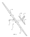
- FIG. 1 shows the general geometry of an aircraft 10 as an airborne vehicle on which the embodiments described could be implemented.
- Aircraft 10 has a fuselage 12, left and right wings 14a and 14b, vertical stabilizer 16 and left and right horizontal stabilizers 18a and 18b.
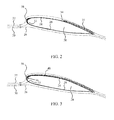
- the wings 14a and 14b employ airfoil shapes as shown in FIGs. 2 and 3 which produce laminar flow under nominal flight conditions.
- the free stream flows around the airfoil 20 as represented by stream line 22 over the upper or suction surface 24 and stream line 26 under the lower or pressure surface 28.
- Stagnation stream line 3 0 impinges the airfoil at the stagnation point 32.
- FIG. 1 shows the general geometry of an aircraft 10 as an airborne vehicle on which the embodiments described could be implemented.
- Aircraft 10 has a fuselage 12, left and right wings 14a and 14b, vertical stabilizer 16 and left and right horizontal stabilizers 18a and 18b.
- the wings 14a and 14b employ airfoil shapes as shown in FIGs.
- a laminar to turbulent transition point 34 is present (nominally aft of the mid chord) with subsequent turbulent flow represented by element 35.
- a DBD actuator 36 is integrated into the leading edge 38 of the airfoil as shown in FIG. 3 .
- the laminar flow is "tripped” resulting in turbulent flow (represented by element 40 in FIG. 3 ) being initiated at or near the leading edge 38 thereby decreasing lift and increasing drag on the airfoil.
- laminar flow is reestablished returning to the flow state shown in FIG. 2 .
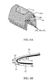
- DBD actuators may be arranged in streamwise array as shown in FIG. 4 such that successive DBD actuators 36b (on the upper or suction surface) and 36c and 36d (on the lower or pressure surface) are located downstream of initial DBD actuator 36a to maintain transition (in the event of relaminarization) or to independently trip a reduced extent of flow for reduced control authority.
- the two actuators illustrated in FIG. 4 on each of the suction and pressure surfaces control transition on both the upper and lower sides of the wing section.
- an outer electrode 42 is substantially flush with the aerodynamic surface 44 of the wing.
- the surface electrode must be substantially aerodynamically flush with the aircraft skin (i.e. does not passively trip the laminar flow).
- a dielectric layer 46 separates the outer electrode 42 from an inner electrode 48.
- the DBD actuators for an example embodiment employ three layers of polyimide film 50a, 50b and 50c joined with pressure sensitive adhesive layers 54a, 54b.
- Outer electrode 42 is an etched copper foil on film layer 50a while the inner electrode 48 is an etched copper foil on the inside surface of film layer 50c.
- Spanwise length of the electrodes in FIG. 6A has been shortened for clarity.
- the polyimide film layers are 5.0 mil thickness with the adhesive layers being 2.0 mil VHB (Very High Bond available from 3M).
- the etched copper electrodes are 0.3 mil in thickness.
- Example fabrication techniques for the DBD actuators may be as disclosed in US patent application serial no. 12/762,562 filed on 19 April 2010 entitled Laminated Plasma Actuator (attorney docket no. 10-0041) the disclosure of which is incorporated herein by reference.
- FIG 6B example dimensions for the DBD actuator laminates of FIG.
- 6A are an outer electrode length 56 of approximately 0.5 inches and an inner electrode length 58 of approximately 1.5 inches.
- the dielectric layers extend along the wing surface from the chord centerline 60 for a distance 62 of approximately 1.8 inches and a distance 64 of 3.5 inches.
- An alternative embodiment integrates actuators into the composite skin of the wing exploiting the skin material as the dielectric as opposed to creating drop-in actuators as illustrated.
- a "smooth" electrode to avoid tripping the laminar boundary layer until the DBD actuator is activated, structural composites with robotically applied nickel-based electrodes for environmental compatibility may be employed.
- the surface (outer) and encapsulated (inner) electrode arrangement is not critical to effectiveness and the encapsulated electrode may be "upstream" of surface electrode.
- the upper or suction surface actuation accomplishes the majority of the control effect and is therefore most effective.
- the upper surface boundary layer is tripped downstream of stagnation point but DBD actuator control authority to trip the boundary layer is most effective as the actuator is moved toward the leading edge stagnation point.
- the stagnation point location may vary with respect to airspeed and angle of attack. However, ideally the actuator is placed at the stagnation point as shown in FIG. 3 for actuator 36 and FIG. 4 for actuator 36a.
- control can be segmented into discretely addressable DBD arrays located on the wings 14a and 14b in spanwise zones 70a, 70b, 70c and 72a, 72b, 72c respectively.
- DBD actuator zones with a spanwise length of approximately 25% of total wing half span are located on the outer 75% of the span [unclear].
- the actuation effectiveness for roll is proportional to the distance of the actuated span from the vehicle axis 75. Zoned array elements can be actuated in isolation or in combination with other spanwise array elements to vary the roll control effectiveness. While shown as equal in span in FIG.
- an example implementation is to make the spanwise extent of the zones proportional to the product of spanwise displacement from the vehicle centerline and zoned wing plan area to create uniform roll control effectiveness in each zone. Control zones on both left and right wings to enable roll effectiveness in right-wing-up and right-wing-down senses.
- DBD actuator arrays 74 and 76 may be added for pitch control. Asymmetrical actuation of arrays 74 and 76 may also assist in roll and yaw control. Similar arrangement of DBD actuator arrays on the vertical stabilizer may also be employed for yaw control.
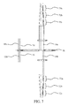
- Control of the DBD actuator arrays is accomplished as shown in FIG. 8 .
- the aircraft power system 80 provides basic electrical power for the actuators.
- a high voltage converter 82 provides the high voltage/high frequency power required by the DBD acutators and a power distributor 84 under control of a control computer 86 distributes the power to the individual actuators (shown as spanwise arrays 88a, 88b on the left wing and 90a and 90b on the right wing. In exemplary embodiments frequencies of 1 - 10 kHz are anticipated.
- these arrays may be individual actuators such as DBD actuator 3 6 of FIG. 3 or streamwise distributed actuator arrays of DBD actuators 36a, 36b, 36c and 36d as shown in FIG. 4 .
- the control computer 86 receives a control input 87 from an operator and determines the required control authority to execute that control input, providing power to a selected activation array that may include either or both spanwise elements or streamwise elements (with potential additional selection of upper (suction) or lower (pressure) surface elements) as necessary from a first unpowered operating configuration to a second powered operating configuration to achieve and maintain the calculated control authority by tripping the laminar boundary layer over a desired portion of the wing or other aerodynamic surface.
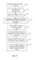
- step 900 the control computer assess flight parameters such as altitude, airspeed and attitude, step 902.
- the control computer determines an activation array of DBD actuators which may be selection of one or more spanwise zones of actuators, step 906, for energizing to meet the control response requirement.
- the activation array may include streamwise DBD actuators for enhanced or reduced control authority or to maintain laminar separation and turbulence in the stream, step 908.
- the activation array may include upper (suction) surface DBD actuators or lower (pressure surface) actuators, step 910.
- the activation array selection process by the control computer may be a table look up [?] based on flight parameters and control input or may be a calculated result based on predetermined flight control laws for the aircraft.
- the control computer then provides power to the selected activation array, step 912.
- the control computer removes power from the activation array, step 914, allowing resumption of laminar flow on the aerodynamic surface.
- the control input resulting from the activation array is substantially immediate allowing very precise control timing and modulation of the DBD actuators in the selected activation array allows very precise control application.
- disbursement of the DBD actuators both spanwise and streamwise allows very precise control not only for flight control in roll, yaw or pitch but for gust load alleviation and dynamic aeroelastic control of flexible high aspect ratio wings.
- a surface, flush-mounted shear stress sensor could be employed downstream of the actuators to detect and monitor boundary layer state for actuator feedback control, performance & health monitoring.
Landscapes
- Engineering & Computer Science (AREA)
- Aviation & Aerospace Engineering (AREA)
- Plasma Technology (AREA)
- Aerodynamic Tests, Hydrodynamic Tests, Wind Tunnels, And Water Tanks (AREA)
Applications Claiming Priority (1)
| Application Number | Priority Date | Filing Date | Title |
|---|---|---|---|
| US13/462,170 US20130292511A1 (en) | 2012-05-02 | 2012-05-02 | Dielectric barrier discharge flight control system through modulated boundary layer transition |
Publications (2)
| Publication Number | Publication Date |
|---|---|
| EP2660149A2 true EP2660149A2 (fr) | 2013-11-06 |
| EP2660149A3 EP2660149A3 (fr) | 2015-06-10 |
Family
ID=48325429
Family Applications (1)
| Application Number | Title | Priority Date | Filing Date |
|---|---|---|---|
| EP13166333.8A Withdrawn EP2660149A3 (fr) | 2012-05-02 | 2013-05-02 | Système de commande de vol de décharge à barrière diélectrique par l'intermédiaire d'une transition de couche limite modulée |
Country Status (6)
| Country | Link |
|---|---|
| US (1) | US20130292511A1 (fr) |
| EP (1) | EP2660149A3 (fr) |
| JP (1) | JP2013233921A (fr) |
| CN (1) | CN103381884A (fr) |
| AU (1) | AU2013200785A1 (fr) |
| CA (1) | CA2804729A1 (fr) |
Families Citing this family (7)
| Publication number | Priority date | Publication date | Assignee | Title |
|---|---|---|---|---|
| WO2014081355A1 (fr) * | 2012-11-20 | 2014-05-30 | Saab Ab | Bande de protection contre l'érosion pour bord d'attaque d'article à profil aérodynamique |
| JP6403156B2 (ja) * | 2014-10-28 | 2018-10-10 | 東芝エネルギーシステムズ株式会社 | 気流発生装置、および、風力発電システム |
| US9868525B2 (en) * | 2015-09-25 | 2018-01-16 | The Boeing Company | Low speed airfoil design for aerodynamic improved performance of UAVs |
| GB2561880A (en) * | 2017-04-27 | 2018-10-31 | Airbus Operations Ltd | Aerodynamic body |
| CN112977879A (zh) * | 2021-04-01 | 2021-06-18 | 中国航天空气动力技术研究院 | 一种气弹试验平台 |
| CN116395132B (zh) * | 2023-06-07 | 2023-10-03 | 中国空气动力研究与发展中心计算空气动力研究所 | 一种超声速边界层转捩控制结构 |
| CN116976245B (zh) * | 2023-09-19 | 2023-11-28 | 中国航空工业集团公司沈阳空气动力研究所 | 一种基于微纳米多尺度表面结构的流动转捩控制方法 |
Family Cites Families (14)
| Publication number | Priority date | Publication date | Assignee | Title |
|---|---|---|---|---|
| US5320309A (en) * | 1992-06-26 | 1994-06-14 | British Technology Group Usa, Inc. | Electromagnetic device and method for boundary layer control |
| US5901928A (en) * | 1996-06-14 | 1999-05-11 | Aptek, Inc. | Active turbulence control technique for drag reduction |
| US6570333B1 (en) * | 2002-01-31 | 2003-05-27 | Sandia Corporation | Method for generating surface plasma |
| US6805325B1 (en) * | 2003-04-03 | 2004-10-19 | Rockwell Scientific Licensing, Llc. | Surface plasma discharge for controlling leading edge contamination and crossflow instabilities for laminar flow |
| US7703479B2 (en) * | 2005-10-17 | 2010-04-27 | The University Of Kentucky Research Foundation | Plasma actuator |
| US7624941B1 (en) * | 2006-05-02 | 2009-12-01 | Orbital Research Inc. | Method of controlling aircraft, missiles, munitions and ground vehicles with plasma actuators |
| US8016246B2 (en) * | 2007-05-25 | 2011-09-13 | The Boeing Company | Plasma actuator system and method for use with a weapons bay on a high speed mobile platform |
| US8220753B2 (en) * | 2008-01-04 | 2012-07-17 | The Boeing Company | Systems and methods for controlling flows with pulsed discharges |
| US9446840B2 (en) * | 2008-07-01 | 2016-09-20 | The Boeing Company | Systems and methods for alleviating aircraft loads with plasma actuators |
| US8220754B2 (en) * | 2009-06-03 | 2012-07-17 | Lockheed Martin Corporation | Plasma enhanced riblet |
| US9975625B2 (en) * | 2010-04-19 | 2018-05-22 | The Boeing Company | Laminated plasma actuator |
| WO2012036602A1 (fr) * | 2010-09-15 | 2012-03-22 | Saab Ab | Système actionneur à écoulement laminaire actif assisté par plasma |
| US9090326B2 (en) * | 2010-10-13 | 2015-07-28 | The Boeing Company | Active flow control on a vertical stabilizer and rudder |
| US8523115B2 (en) * | 2011-01-28 | 2013-09-03 | Lockheed Martin Corporation | System, apparatus, program product, and related methods for providing boundary layer flow control |
-
2012
- 2012-05-02 US US13/462,170 patent/US20130292511A1/en not_active Abandoned
-
2013
- 2013-02-05 CA CA2804729A patent/CA2804729A1/fr not_active Abandoned
- 2013-02-08 AU AU2013200785A patent/AU2013200785A1/en not_active Abandoned
- 2013-04-23 JP JP2013089932A patent/JP2013233921A/ja active Pending
- 2013-04-26 CN CN2013101495539A patent/CN103381884A/zh active Pending
- 2013-05-02 EP EP13166333.8A patent/EP2660149A3/fr not_active Withdrawn
Also Published As
| Publication number | Publication date |
|---|---|
| CA2804729A1 (fr) | 2013-11-02 |
| AU2013200785A1 (en) | 2013-11-21 |
| CN103381884A (zh) | 2013-11-06 |
| EP2660149A3 (fr) | 2015-06-10 |
| US20130292511A1 (en) | 2013-11-07 |
| JP2013233921A (ja) | 2013-11-21 |
Similar Documents
| Publication | Publication Date | Title |
|---|---|---|
| EP2660149A2 (fr) | Système de commande de vol de décharge à barrière diélectrique par l'intermédiaire d'une transition de couche limite modulée | |
| US7988101B2 (en) | Airfoil trailing edge plasma flow control apparatus and method | |
| EP2321084B1 (fr) | Système et procédé pour une commande d'écoulement aérodynamique | |
| EP2505782B1 (fr) | Générateurs de vortex à activation de plasma | |
| EP2441669B1 (fr) | Contrôle de flux actif sur un stabilisateur vertical et gouvernail | |
| JP5255903B2 (ja) | 空中移動プラットフォームの飛行を制御する方法および物体の表面上の境界層流に影響を及ぼすためのプラズマアクチュエータ | |
| US9834301B1 (en) | Method of increasing the performance of aircraft, missiles, munitions and ground vehicles with plasma actuators | |
| EP1995172B1 (fr) | Système actionneur de plasma et procédé à utiliser avec une soute d'armes dans une plate-forme mobile à grande vitesse | |
| EP2069199B1 (fr) | Générateurs de vortex sur pales de rotor pour retarder le debut de moments de grand tangage oscillatoire et augmenter la portance maximale | |
| US9541106B1 (en) | Plasma optimized aerostructures for efficient flow control | |
| EP3323716B1 (fr) | Dispositif de modification d'écoulement d'air d'un aéronef et dispositif de génération de tourbillons pour un aéronef | |
| US11453481B2 (en) | Aerofoil leading edge structures | |
| CN107444614A (zh) | 适用于小型固定翼飞行器的翼面柔性等离子体减阻贴片 | |
| CN207157493U (zh) | 适用于小型固定翼飞行器的翼面柔性等离子体减阻贴片 |
Legal Events
| Date | Code | Title | Description |
|---|---|---|---|
| PUAI | Public reference made under article 153(3) epc to a published international application that has entered the european phase |
Free format text: ORIGINAL CODE: 0009012 |
|
| 17P | Request for examination filed |
Effective date: 20130502 |
|
| AK | Designated contracting states |
Kind code of ref document: A2 Designated state(s): AL AT BE BG CH CY CZ DE DK EE ES FI FR GB GR HR HU IE IS IT LI LT LU LV MC MK MT NL NO PL PT RO RS SE SI SK SM TR |
|
| AX | Request for extension of the european patent |
Extension state: BA ME |
|
| PUAL | Search report despatched |
Free format text: ORIGINAL CODE: 0009013 |
|
| AK | Designated contracting states |
Kind code of ref document: A3 Designated state(s): AL AT BE BG CH CY CZ DE DK EE ES FI FR GB GR HR HU IE IS IT LI LT LU LV MC MK MT NL NO PL PT RO RS SE SI SK SM TR |
|
| AX | Request for extension of the european patent |
Extension state: BA ME |
|
| RIC1 | Information provided on ipc code assigned before grant |
Ipc: B64C 23/00 20060101AFI20150507BHEP |
|
| STAA | Information on the status of an ep patent application or granted ep patent |
Free format text: STATUS: THE APPLICATION IS DEEMED TO BE WITHDRAWN |
|
| 18D | Application deemed to be withdrawn |
Effective date: 20151201 |