EP2322065A2 - Distributeur de fluide - Google Patents
Distributeur de fluide Download PDFInfo
- Publication number
- EP2322065A2 EP2322065A2 EP10013696A EP10013696A EP2322065A2 EP 2322065 A2 EP2322065 A2 EP 2322065A2 EP 10013696 A EP10013696 A EP 10013696A EP 10013696 A EP10013696 A EP 10013696A EP 2322065 A2 EP2322065 A2 EP 2322065A2
- Authority
- EP
- European Patent Office
- Prior art keywords
- fluid dispenser
- counter
- dispenser according
- actuating mechanism
- counting device
- Prior art date
- Legal status (The legal status is an assumption and is not a legal conclusion. Google has not performed a legal analysis and makes no representation as to the accuracy of the status listed.)
- Granted
Links
Images


Classifications
-
- A—HUMAN NECESSITIES
- A47—FURNITURE; DOMESTIC ARTICLES OR APPLIANCES; COFFEE MILLS; SPICE MILLS; SUCTION CLEANERS IN GENERAL
- A47K—SANITARY EQUIPMENT; ACCESSORIES THEREFOR, e.g. TOILET ACCESSORIES
- A47K5/00—Holders or dispensers for soap, toothpaste or the like
- A47K5/06—Dispensers for soap
- A47K5/12—Dispensers for soap for liquid or pasty soap
- A47K5/1202—Dispensers for soap for liquid or pasty soap dispensing dosed volume
-
- B—PERFORMING OPERATIONS; TRANSPORTING
- B05—SPRAYING OR ATOMISING IN GENERAL; APPLYING FLUENT MATERIALS TO SURFACES, IN GENERAL
- B05B—SPRAYING APPARATUS; ATOMISING APPARATUS; NOZZLES
- B05B11/00—Single-unit hand-held apparatus in which flow of contents is produced by the muscular force of the operator at the moment of use
- B05B11/01—Single-unit hand-held apparatus in which flow of contents is produced by the muscular force of the operator at the moment of use characterised by the means producing the flow
- B05B11/10—Pump arrangements for transferring the contents from the container to a pump chamber by a sucking effect and forcing the contents out through the dispensing nozzle
- B05B11/1042—Components or details
- B05B11/108—Means for counting the number of dispensing strokes
Definitions
- the present invention relates to a fluid dispenser having an actuating mechanism operable by a pumping mechanism disposed in a dispenser housing, wherein a counter coupled to the actuating mechanism detects the actions of the pumping mechanism.
- a fluid dispenser which is operated with one hand.
- the hand is held under a vertically lower end of the fluid dispenser, at the same time pushing an actuating lever provided in the region of the vertically lower end and accessible from a front side of the fluid dispenser with the palm of the hand of the same hand.
- an actuating lever provided in the region of the vertically lower end and accessible from a front side of the fluid dispenser with the palm of the hand of the same hand.
- fluid is conveyed into the actuating hand, wherein a running within a housing of the fluid dispenser spout has its outlet opening at the vertical lower end of the fluid dispenser, so that the held under the housing actuating hand is filled.
- a device is further operated, which detects the actuation of the actuating lever and display operating information via a display, which is readable via a window in a vertically extending front wall of the housing.
- the present invention has for its object to provide a fluid dispenser, which has a good functionality and has a actions of a pump mechanism of the fluid dispenser sensing counter that is integrated as well as possible in the dispenser.
- the counting device is provided on the projecting outflow section, it is in a prominent position, but nevertheless is well integrated in the fluid dispenser.
- This also has the advantage that the basic structure of the fluid dispenser can be substantially maintained as it is for a fluid dispenser without counter is used.
- the counter provided on the outlet portion, good operation of the operating mechanism and the pumping mechanism is possible, and good interaction of the operating mechanism and counter is possible.
- the counter can be designed to be detachable from the dispenser housing together with the outlet section.
- the counter is easily accessible for maintenance purposes, for example, and can also be easily replaced together with the spout section.
- the outlet section can release access to a reset arrangement of the counter in a maintenance position and cover the reset arrangement in a ready position.
- trained personnel can easily reset the counter, while preventing untrained users of the fluid dispenser from returning the counter unauthorized.
- the counting device can be provided detachably from the outlet section in a particularly favorable manner.
- the counter can be exchanged and the outlet section can continue to be used.
- the counter can have a meter housing, which can be inserted into the outlet section and receives a counter. With the counter housing, the counter can be protected against external influences.
- the meter housing can have a light cutout for a display located behind it. This allows the display to be read through the meter housing.
- Particularly favorable may be provided on the meter housing a reset actuator, with which a return means of the counter can be triggered. In this way, the return means can be triggered indirectly.
- the counter can have a sensor which is designed to measure without contact, in particular by approaching, a movement of the actuating mechanism.
- the sensor works wear-free.
- a sensor associated with the marking means may be provided on the actuating mechanism, on which the sensor is designed to be responsive.
- the marking means marks the movement of the actuating mechanism for the sensor.
- the senor can be designed as a reed contact and the marking means a magnetic element provided on the actuating mechanism.
- the magnetic element moves relative to the sensor, the magnetic field changes in the region of the sensor, which detects this as a reed contact.
- it can be adjustable in which proportion of a maximum possible movement of the actuating mechanism, the counter continues to count.
- the counter can be ensured that the counter only continues counting when a minimum amount of fluid is dispensed.
- a relative position can be adjustable, which have a sensor of the counter and a sensor associated with the marking means of the actuating mechanism to each other when the actuating mechanism is in an initial position.
- a triggering time is adjustable at which the counter continues to count.
- Particularly favorable can be detected with the counter, up to what proportion of a maximum possible movement of the actuating mechanism is moved.
- the proportion of movement gives information about an actually promoted in a movement action amount of fluid.
- the motion components can be compiled with the counter. From this it can be determined how much fluid was pumped in several, possibly also incomplete actuation actions in total.
- the counter can be detachable from the outlet section and replaced by a cover panel.
- the outlet section can be reused after disassembly of the counter.
- a filler panel can be replaced by a counter.
- outlet section with counter wherein the outlet section may be releasably attachable to the fluid dispenser.
- the outlet section with counter can be exchangeable against a discharge section without counter and vice versa.
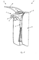
- FIG. 1 shows a fluid dispenser 1 according to the invention without a fluid bottle.
- the fluid dispenser 1 has an actuating mechanism 2, a pumping mechanism 3, a dispenser housing 4 and a discharge section 5 projecting from the dispenser housing with counter 6 provided thereon.
- the outlet section 5 projects transversely to the longitudinal direction of the fluid dispenser.
- the longitudinal axis of the fluid dispenser extends approximately vertically and the outlet portion is provided at a vertically upper end 7 of the fluid dispenser 1.
- the outlet section 5 covers an outlet pipe 8, from which in FIG. 1 only a distal end 9 is visible, which protrudes below the outlet section 5.
- the spout 8 is connected to the pumping mechanism 3, which is disposed within the dispenser housing 4.
- the pumping mechanism 3 is operated by means of the operating mechanism 2, of which in FIG. 1 only an approximately U-shaped operating lever 10 is visible.
- the outlet section 5 has lateral recesses 11, in which the operating lever 10 can move in a pivoting manner.
- the outlet portion 5 of a in FIG. 1 shown stand-by position upwards into a maintenance position in which the outlet pipe 8 is released and an interior of the outlet section is accessible.
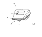
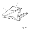
- the outlet section 5 with the counter 6 is removable from the fluid dispenser 1 and in FIG. 2 shown individually in a perspective front view.
- the counter 6 has a meter housing 12, which is inserted into the outlet section 5 and which receives a counter 13. From the meter housing 12 is in FIG. 2 only an upper housing part 14 with a light aperture 15 visible. Through the window-like cutout 15, an underlying display 16 of the counter 13 is read.
- the display 16 may be formed as a display.
- the counter 6 is provided detachably from the outlet section 5.
- the upper housing part 14 of the meter housing 12 is shown individually. It has a provided on three sides, continuous, flange-like collar 17. If the upper housing part is inserted from the inside into a receiving opening 18 of the outlet section 15, the bearing collar 17 comes into contact with the outlet section 5 inside. In the region of a front side 19 of the upper housing part 14, a downwardly projecting hook 20 is formed. In this embodiment of the invention, the hook 20 is integrally formed on the support collar 17.
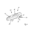
- the counter 13 is shown in a perspective side view. On its top 21, to which the display 16 is provided, it has a reset button 22 as a return means. By pressing the reset button 22, the display 16 is reset.
- the counter 13 has a sensor 23, which is formed in this embodiment of the invention as a reed contact. The sensor 23 is connected via electrical connections 25, 26 to a counting device in the interior of the counter 13.
- a battery 27 is also provided.
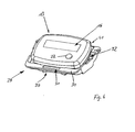
- FIG. 5 a housing bottom part 28 of the meter housing 12 is shown in a perspective view, wherein an inner region of the housing lower part is visible. At a front side 29, it has a flange 30 with an opening 31. In the opening 31, the hook 20 of the housing upper part 14 is inserted.
- the lower housing part 28 has a recess 32 for receiving the counter 13.
- the sensor 23 is positioned in a receiving chamber 34, which is formed on a rear side 33 of the housing lower part 28, in particular open to the rear. That is, the sensor 23 is housed in an outer region of the housing base 28, that is, outside the trough 32.
- the open receiving chamber 34 is bounded upward by a hook-like projection 35.
- the lower housing part 28 has a reset actuation device 36, with which pressure can be exerted on the counter 13.
- the return actuator 36 is tongue-like and has a button 37 at its free end.
- the button 37 webs 38, 39 over which a force applied from the outside to the key 37 force can be transferred to the counter 13 when this is inserted into the trough 32.
- the return transfer device 36 is on sides the rear side 33 of the lower housing part 28 is articulated to a bottom 42 of the trough 32 and its free end points towards the front side 29 of the housing lower part 28.
- the lower housing part 28 also has two lateral resilient retaining webs 40, 41.
- the holding webs 40, 41 are hinged to the bottom 42 of the trough 32 and extending, forming part of the trough, to the back 33 of the housing base 28 and then upwards.
- FIG. 6 shows the counter 13 in the inserted into the trough 32 of the housing base 28 state.
- the holding webs 40, 41 are located on the back of the counter 13 and hold it in the trough 32.
- the opening 31 of the lower housing part 28 is hooked into the hook 20 of the upper housing part 14 and then with the counter 13 in the direction pivoted to the upper housing part 14 and connected thereto, for example with screws.
- FIG. 7 shows the outlet section 5 with mounted counter 6 in a perspective view from behind.
- the upper housing part 14, and thus the counter 6, is fixed to the outlet section 5 by latching.
- the button 37 of the reset actuator 36 is accessible through an interior 43 of the outlet section 5 and operable by an operator.
- the counter 13 is moved in the counter housing 12 and the reset button 22 is pressed against the upper housing part 14, whereby it is pressed into the counter 13 and the display 16 is reset.
- the reset actuator 36 is part of a return assembly, which also includes the return means 22 of the counter. As long as the button 37 is not pressed, the holding webs 40, 41 hold the counter 13 in a position in which the reset button 22 is sufficiently far away from the upper housing part 14, but at least not pressed unintentionally. In this way it is avoided that the counter 13 is reset by mistake.
- the sensor 23 disposed in the accommodation chamber 34 of the counter 6 is positioned on a back surface 44 of the discharge section when the counter 6 is mounted on the discharge section 5.
- a side 45 of the sensor 23 directed toward the rear side 44 of the outlet section 5 is largely free. It is only slightly obscured by the hook-like projection 35, which holds and engages the sensor 23 in the open receiving chamber 34.
- FIG. 8 shows in a perspective view of the outlet section 5 with the counter 6, the pump mechanism 3, and a part of the actuating mechanism 2, in particular its operating lever 10.
- the operating lever 10 has at a proximal end 46 a connecting web 47, which U-arms 48, 49 of the operating lever 10 connects to each other.
- the connecting web 47 is provided adjacent to the rear side 44 of the outlet section 5 and pivots along this rear side 44 when the operating lever 10 is actuated.
- the magnetic element 50 is fastened to the connecting web 47 with the aid of a fastening device 51. In this way, it is guided past the sensor 23 when the operating lever 10 is actuated.
- the sensor 23 detects the change of the magnetic field in its vicinity and the counter 13 counts one step further, if the magnetic field detected by the sensor 23 has changed correspondingly during an up and down movement of the operating lever 10.
- FIG. 9 shows the fluid dispenser 1 according to the invention in a longitudinal sectional view with an inserted fluid bottle 52, for reasons of clarity, however, without the pumping mechanism 3 and without outlet pipe.
- FIG. 10 is an enlarged view of the vertically upper end 7 of the fluid dispenser 1 according to FIG. 9 , Here, the position of the magnetic element 50 relative to the sensor 23 can be seen when the operating lever 10 is in an upper starting position. It is also shown how the counting device 6 is inserted into the receiving opening 18 of the fluid diaphragm 5.
- the relative position which the sensor 23 and the magnetic element 50 have when the actuating mechanism 2, in particular the operating lever 10, in its initial position can be adjustable.
- the triggering time of the counter is adjustable, for example, to a value of 30%, 50% or 70% of the maximum path of movement of the operating lever 10 or the actuating mechanism 2.
- a pushing mechanism or a grid can be provided on the fastening device 51. It would also be possible to attach the magnetic element 50 to a set screw.
- the counter can be detected with the counter, up to what proportion of a maximum possible movement or a maximum possible stroke of the actuating mechanism or its operating lever has been moved.
- the proportion can be displayed with decimal places.
- the amount of fluid conveyed during the movement action can be determinable and can be displayed in a volume unit.
- the counter can be designed so that it compresses the motion components. The compressed result can be detected, for example, in the form of a number with decimal places or in the form of a volume.
- the total sum could be 1.16 or, as a volume, 2.32 ml.
- the counter 6 is detachable from the outlet section 5 and replaceable against a cover 53.
- the outlet section 5 is shown with cover 53.
- a discharge section with counter 6 can be converted to a discharge section without counting device, wherein the receiving opening 18 is closed by the Abdeckdeckblende 53.
- a provided with cover panel outlet section can be converted to a discharge section with counter.
Landscapes
- Health & Medical Sciences (AREA)
- Public Health (AREA)
- Loading And Unloading Of Fuel Tanks Or Ships (AREA)
- Containers And Packaging Bodies Having A Special Means To Remove Contents (AREA)
- Devices For Dispensing Beverages (AREA)
Applications Claiming Priority (1)
| Application Number | Priority Date | Filing Date | Title |
|---|---|---|---|
| DE202009015766U DE202009015766U1 (de) | 2009-11-17 | 2009-11-17 | Fluidspender |
Publications (3)
| Publication Number | Publication Date |
|---|---|
| EP2322065A2 true EP2322065A2 (fr) | 2011-05-18 |
| EP2322065A3 EP2322065A3 (fr) | 2014-02-26 |
| EP2322065B1 EP2322065B1 (fr) | 2016-08-17 |
Family
ID=42055601
Family Applications (1)
| Application Number | Title | Priority Date | Filing Date |
|---|---|---|---|
| EP10013696.9A Active EP2322065B1 (fr) | 2009-11-17 | 2010-10-15 | Distributeur de fluide |
Country Status (2)
| Country | Link |
|---|---|
| EP (1) | EP2322065B1 (fr) |
| DE (1) | DE202009015766U1 (fr) |
Families Citing this family (2)
| Publication number | Priority date | Publication date | Assignee | Title |
|---|---|---|---|---|
| DE102017112729A1 (de) | 2017-06-09 | 2018-12-13 | Paul Hartmann Ag | Spendersystem für flüssige Medien |
| DE202023105507U1 (de) * | 2023-09-21 | 2023-10-12 | Huonker Gmbh | Vorrichtung zum Abgeben eines Fluids, insbesondere eines Reinigungs-, Pflege- oder Desinfektionsfluids für Hände |
Citations (2)
| Publication number | Priority date | Publication date | Assignee | Title |
|---|---|---|---|---|
| US5771925A (en) | 1996-11-27 | 1998-06-30 | Lewandowski; James | Soap dispenser and wash signal device |
| US6707873B2 (en) | 1998-06-11 | 2004-03-16 | Ecolab Inc. | Usage competent hand soap dispenser with data collection and display capabilities |
Family Cites Families (4)
| Publication number | Priority date | Publication date | Assignee | Title |
|---|---|---|---|---|
| GB857189A (en) * | 1958-08-22 | 1960-12-29 | Walter Scherb | Device for dispensing portions of liquid, particularly of spirituous liquors |
| FR2775578B1 (fr) * | 1998-03-04 | 2000-05-05 | Prodene Klint Lab | Distributeur avec avertisseur du niveau du contenu |
| GB0328859D0 (en) * | 2003-12-12 | 2004-01-14 | Clinical Designs Ltd | Dispenser and counter |
| CN101810901B (zh) * | 2005-01-20 | 2013-07-24 | 特鲁德尔医学国际公司 | 分配装置 |
-
2009
- 2009-11-17 DE DE202009015766U patent/DE202009015766U1/de not_active Expired - Lifetime
-
2010
- 2010-10-15 EP EP10013696.9A patent/EP2322065B1/fr active Active
Patent Citations (2)
| Publication number | Priority date | Publication date | Assignee | Title |
|---|---|---|---|---|
| US5771925A (en) | 1996-11-27 | 1998-06-30 | Lewandowski; James | Soap dispenser and wash signal device |
| US6707873B2 (en) | 1998-06-11 | 2004-03-16 | Ecolab Inc. | Usage competent hand soap dispenser with data collection and display capabilities |
Also Published As
| Publication number | Publication date |
|---|---|
| DE202009015766U1 (de) | 2010-03-25 |
| EP2322065B1 (fr) | 2016-08-17 |
| EP2322065A3 (fr) | 2014-02-26 |
Similar Documents
| Publication | Publication Date | Title |
|---|---|---|
| EP1216720B1 (fr) | Moyen pour enregistrer l'actionnement d'un inhalateur | |
| EP3135386A1 (fr) | Atomiseur | |
| DE202007015396U1 (de) | Sprühvorrichtung zum periodischen Ausstoßen von Sprühmaterial | |
| EP0853458B1 (fr) | Distributeur-doseur de liquides | |
| EP2488078A1 (fr) | Distributeur-doseur mural | |
| EP2676588B1 (fr) | Distributeur destiné à être fixé au mur pour des liquides, en particulier des savons liquides et des produits de désinfection alcooliques, doté d'une pompe de dosage remplaçable | |
| DE202016104190U1 (de) | Selbstdesinfizierende Türklinkeneinrichtung sowie Tür mit einer solchen | |
| DE2727679A1 (de) | Seifenspender | |
| DE3225911A1 (de) | Dosier- oder zerstaeuberpumpe mit einem pumpengehaeuse und einem betaetigungsdruecker | |
| DE2932848C2 (de) | Seifenspender für Flüssigseifen | |
| DE102012214780A1 (de) | Türbetätigungselement mit Desinfektions- oder Reinigungseinrichtung | |
| EP2322065B1 (fr) | Distributeur de fluide | |
| DE102015100201B4 (de) | Dosierspender | |
| DE102004063889B4 (de) | Dosiervorrichtung, insbesondere Handreinigungs- und Desinfektionsmittelspender mit vereinfachtem Pumpenaustausch nach vorn | |
| EP3442629B1 (fr) | Appareil à main destiné à distribuer une substance pharmaceutique ainsi que compteur pour un tel appareil à main | |
| EP2177141B1 (fr) | Distributeur avec un compteur électronique | |
| EP3174639B1 (fr) | Distributeur sans contact pour distribuer des milieux liquides | |
| EP3097833B1 (fr) | Brosse de nettoyage des toilettes | |
| DE102005036197B4 (de) | Inhalier-Gerät | |
| EP2198763A2 (fr) | Siège de toilettes | |
| DE102011115712B3 (de) | Behältereinrichtung | |
| WO2005006931A1 (fr) | Distributeur pour des milieux liquides ou pateux | |
| EP3942983B1 (fr) | Dispositif de désinfection pour poignées de brosse de toilette | |
| DE69209150T2 (de) | Flüssigseifenspender | |
| DE102018120827A1 (de) | Spendersystem zum Ausgeben eines Mediums zur Hautreinigung und/oder Hauptpflege |
Legal Events
| Date | Code | Title | Description |
|---|---|---|---|
| PUAI | Public reference made under article 153(3) epc to a published international application that has entered the european phase |
Free format text: ORIGINAL CODE: 0009012 |
|
| AK | Designated contracting states |
Kind code of ref document: A2 Designated state(s): AL AT BE BG CH CY CZ DE DK EE ES FI FR GB GR HR HU IE IS IT LI LT LU LV MC MK MT NL NO PL PT RO RS SE SI SK SM TR |
|
| AX | Request for extension of the european patent |
Extension state: BA ME |
|
| PUAL | Search report despatched |
Free format text: ORIGINAL CODE: 0009013 |
|
| RIC1 | Information provided on ipc code assigned before grant |
Ipc: B05B 11/00 20060101ALI20140115BHEP Ipc: A47K 5/12 20060101AFI20140115BHEP |
|
| AK | Designated contracting states |
Kind code of ref document: A3 Designated state(s): AL AT BE BG CH CY CZ DE DK EE ES FI FR GB GR HR HU IE IS IT LI LT LU LV MC MK MT NL NO PL PT RO RS SE SI SK SM TR |
|
| AX | Request for extension of the european patent |
Extension state: BA ME |
|
| 17P | Request for examination filed |
Effective date: 20140826 |
|
| RBV | Designated contracting states (corrected) |
Designated state(s): AL AT BE BG CH CY CZ DE DK EE ES FI FR GB GR HR HU IE IS IT LI LT LU LV MC MK MT NL NO PL PT RO RS SE SI SK SM TR |
|
| GRAP | Despatch of communication of intention to grant a patent |
Free format text: ORIGINAL CODE: EPIDOSNIGR1 |
|
| INTG | Intention to grant announced |
Effective date: 20160309 |
|
| GRAS | Grant fee paid |
Free format text: ORIGINAL CODE: EPIDOSNIGR3 |
|
| GRAA | (expected) grant |
Free format text: ORIGINAL CODE: 0009210 |
|
| AK | Designated contracting states |
Kind code of ref document: B1 Designated state(s): AL AT BE BG CH CY CZ DE DK EE ES FI FR GB GR HR HU IE IS IT LI LT LU LV MC MK MT NL NO PL PT RO RS SE SI SK SM TR |
|
| REG | Reference to a national code |
Ref country code: GB Ref legal event code: FG4D Free format text: NOT ENGLISH |
|
| REG | Reference to a national code |
Ref country code: CH Ref legal event code: EP |
|
| REG | Reference to a national code |
Ref country code: IE Ref legal event code: FG4D Free format text: LANGUAGE OF EP DOCUMENT: GERMAN |
|
| REG | Reference to a national code |
Ref country code: AT Ref legal event code: REF Ref document number: 820231 Country of ref document: AT Kind code of ref document: T Effective date: 20160915 |
|
| REG | Reference to a national code |
Ref country code: DE Ref legal event code: R096 Ref document number: 502010012193 Country of ref document: DE |
|
| REG | Reference to a national code |
Ref country code: NL Ref legal event code: FP |
|
| REG | Reference to a national code |
Ref country code: DE Ref legal event code: R081 Ref document number: 502010012193 Country of ref document: DE Owner name: OP-HYGIENE IP GMBH, CH Free format text: FORMER OWNER: INGO-MANUFACTURING LTD., BALLYMOTE, SLIGO, IE Ref country code: DE Ref legal event code: R082 Ref document number: 502010012193 Country of ref document: DE Representative=s name: GRUENECKER PATENT- UND RECHTSANWAELTE PARTG MB, DE |
|
| REG | Reference to a national code |
Ref country code: LT Ref legal event code: MG4D |
|
| PG25 | Lapsed in a contracting state [announced via postgrant information from national office to epo] |
Ref country code: LT Free format text: LAPSE BECAUSE OF FAILURE TO SUBMIT A TRANSLATION OF THE DESCRIPTION OR TO PAY THE FEE WITHIN THE PRESCRIBED TIME-LIMIT Effective date: 20160817 Ref country code: FI Free format text: LAPSE BECAUSE OF FAILURE TO SUBMIT A TRANSLATION OF THE DESCRIPTION OR TO PAY THE FEE WITHIN THE PRESCRIBED TIME-LIMIT Effective date: 20160817 Ref country code: RS Free format text: LAPSE BECAUSE OF FAILURE TO SUBMIT A TRANSLATION OF THE DESCRIPTION OR TO PAY THE FEE WITHIN THE PRESCRIBED TIME-LIMIT Effective date: 20160817 Ref country code: IT Free format text: LAPSE BECAUSE OF FAILURE TO SUBMIT A TRANSLATION OF THE DESCRIPTION OR TO PAY THE FEE WITHIN THE PRESCRIBED TIME-LIMIT Effective date: 20160817 Ref country code: NO Free format text: LAPSE BECAUSE OF FAILURE TO SUBMIT A TRANSLATION OF THE DESCRIPTION OR TO PAY THE FEE WITHIN THE PRESCRIBED TIME-LIMIT Effective date: 20161117 Ref country code: HR Free format text: LAPSE BECAUSE OF FAILURE TO SUBMIT A TRANSLATION OF THE DESCRIPTION OR TO PAY THE FEE WITHIN THE PRESCRIBED TIME-LIMIT Effective date: 20160817 |
|
| REG | Reference to a national code |
Ref country code: GB Ref legal event code: 732E Free format text: REGISTERED BETWEEN 20170105 AND 20170111 |
|
| REG | Reference to a national code |
Ref country code: NL Ref legal event code: PD Owner name: OP-HYGIENE IP GMBH; CH Free format text: DETAILS ASSIGNMENT: CHANGE OF OWNER(S), ASSIGNMENT; FORMER OWNER NAME: INGO-MANUFACTURING LTD. Effective date: 20170201 |
|
| PG25 | Lapsed in a contracting state [announced via postgrant information from national office to epo] |
Ref country code: LV Free format text: LAPSE BECAUSE OF FAILURE TO SUBMIT A TRANSLATION OF THE DESCRIPTION OR TO PAY THE FEE WITHIN THE PRESCRIBED TIME-LIMIT Effective date: 20160817 Ref country code: ES Free format text: LAPSE BECAUSE OF FAILURE TO SUBMIT A TRANSLATION OF THE DESCRIPTION OR TO PAY THE FEE WITHIN THE PRESCRIBED TIME-LIMIT Effective date: 20160817 Ref country code: PT Free format text: LAPSE BECAUSE OF FAILURE TO SUBMIT A TRANSLATION OF THE DESCRIPTION OR TO PAY THE FEE WITHIN THE PRESCRIBED TIME-LIMIT Effective date: 20161219 Ref country code: BE Free format text: LAPSE BECAUSE OF NON-PAYMENT OF DUE FEES Effective date: 20161031 Ref country code: GR Free format text: LAPSE BECAUSE OF FAILURE TO SUBMIT A TRANSLATION OF THE DESCRIPTION OR TO PAY THE FEE WITHIN THE PRESCRIBED TIME-LIMIT Effective date: 20161118 Ref country code: SE Free format text: LAPSE BECAUSE OF FAILURE TO SUBMIT A TRANSLATION OF THE DESCRIPTION OR TO PAY THE FEE WITHIN THE PRESCRIBED TIME-LIMIT Effective date: 20160817 Ref country code: PL Free format text: LAPSE BECAUSE OF FAILURE TO SUBMIT A TRANSLATION OF THE DESCRIPTION OR TO PAY THE FEE WITHIN THE PRESCRIBED TIME-LIMIT Effective date: 20160817 |
|
| PG25 | Lapsed in a contracting state [announced via postgrant information from national office to epo] |
Ref country code: RO Free format text: LAPSE BECAUSE OF FAILURE TO SUBMIT A TRANSLATION OF THE DESCRIPTION OR TO PAY THE FEE WITHIN THE PRESCRIBED TIME-LIMIT Effective date: 20160817 Ref country code: EE Free format text: LAPSE BECAUSE OF FAILURE TO SUBMIT A TRANSLATION OF THE DESCRIPTION OR TO PAY THE FEE WITHIN THE PRESCRIBED TIME-LIMIT Effective date: 20160817 |
|
| REG | Reference to a national code |
Ref country code: DE Ref legal event code: R097 Ref document number: 502010012193 Country of ref document: DE |
|
| PG25 | Lapsed in a contracting state [announced via postgrant information from national office to epo] |
Ref country code: BG Free format text: LAPSE BECAUSE OF FAILURE TO SUBMIT A TRANSLATION OF THE DESCRIPTION OR TO PAY THE FEE WITHIN THE PRESCRIBED TIME-LIMIT Effective date: 20161117 Ref country code: SM Free format text: LAPSE BECAUSE OF FAILURE TO SUBMIT A TRANSLATION OF THE DESCRIPTION OR TO PAY THE FEE WITHIN THE PRESCRIBED TIME-LIMIT Effective date: 20160817 Ref country code: SK Free format text: LAPSE BECAUSE OF FAILURE TO SUBMIT A TRANSLATION OF THE DESCRIPTION OR TO PAY THE FEE WITHIN THE PRESCRIBED TIME-LIMIT Effective date: 20160817 Ref country code: CZ Free format text: LAPSE BECAUSE OF FAILURE TO SUBMIT A TRANSLATION OF THE DESCRIPTION OR TO PAY THE FEE WITHIN THE PRESCRIBED TIME-LIMIT Effective date: 20160817 Ref country code: DK Free format text: LAPSE BECAUSE OF FAILURE TO SUBMIT A TRANSLATION OF THE DESCRIPTION OR TO PAY THE FEE WITHIN THE PRESCRIBED TIME-LIMIT Effective date: 20160817 |
|
| REG | Reference to a national code |
Ref country code: CH Ref legal event code: PL |
|
| PLBE | No opposition filed within time limit |
Free format text: ORIGINAL CODE: 0009261 |
|
| STAA | Information on the status of an ep patent application or granted ep patent |
Free format text: STATUS: NO OPPOSITION FILED WITHIN TIME LIMIT |
|
| 26N | No opposition filed |
Effective date: 20170518 |
|
| REG | Reference to a national code |
Ref country code: IE Ref legal event code: MM4A |
|
| REG | Reference to a national code |
Ref country code: FR Ref legal event code: ST Effective date: 20170630 |
|
| PG25 | Lapsed in a contracting state [announced via postgrant information from national office to epo] |
Ref country code: LI Free format text: LAPSE BECAUSE OF NON-PAYMENT OF DUE FEES Effective date: 20161031 Ref country code: CH Free format text: LAPSE BECAUSE OF NON-PAYMENT OF DUE FEES Effective date: 20161031 Ref country code: FR Free format text: LAPSE BECAUSE OF NON-PAYMENT OF DUE FEES Effective date: 20161102 |
|
| PG25 | Lapsed in a contracting state [announced via postgrant information from national office to epo] |
Ref country code: LU Free format text: LAPSE BECAUSE OF NON-PAYMENT OF DUE FEES Effective date: 20161015 Ref country code: SI Free format text: LAPSE BECAUSE OF FAILURE TO SUBMIT A TRANSLATION OF THE DESCRIPTION OR TO PAY THE FEE WITHIN THE PRESCRIBED TIME-LIMIT Effective date: 20160817 |
|
| PG25 | Lapsed in a contracting state [announced via postgrant information from national office to epo] |
Ref country code: IE Free format text: LAPSE BECAUSE OF NON-PAYMENT OF DUE FEES Effective date: 20161015 |
|
| REG | Reference to a national code |
Ref country code: BE Ref legal event code: MM Effective date: 20161031 |
|
| REG | Reference to a national code |
Ref country code: AT Ref legal event code: MM01 Ref document number: 820231 Country of ref document: AT Kind code of ref document: T Effective date: 20161015 |
|
| PG25 | Lapsed in a contracting state [announced via postgrant information from national office to epo] |
Ref country code: AT Free format text: LAPSE BECAUSE OF NON-PAYMENT OF DUE FEES Effective date: 20161015 |
|
| PG25 | Lapsed in a contracting state [announced via postgrant information from national office to epo] |
Ref country code: CY Free format text: LAPSE BECAUSE OF FAILURE TO SUBMIT A TRANSLATION OF THE DESCRIPTION OR TO PAY THE FEE WITHIN THE PRESCRIBED TIME-LIMIT Effective date: 20160817 Ref country code: HU Free format text: LAPSE BECAUSE OF FAILURE TO SUBMIT A TRANSLATION OF THE DESCRIPTION OR TO PAY THE FEE WITHIN THE PRESCRIBED TIME-LIMIT; INVALID AB INITIO Effective date: 20101015 |
|
| PG25 | Lapsed in a contracting state [announced via postgrant information from national office to epo] |
Ref country code: IS Free format text: LAPSE BECAUSE OF FAILURE TO SUBMIT A TRANSLATION OF THE DESCRIPTION OR TO PAY THE FEE WITHIN THE PRESCRIBED TIME-LIMIT Effective date: 20160817 Ref country code: MK Free format text: LAPSE BECAUSE OF FAILURE TO SUBMIT A TRANSLATION OF THE DESCRIPTION OR TO PAY THE FEE WITHIN THE PRESCRIBED TIME-LIMIT Effective date: 20160817 Ref country code: TR Free format text: LAPSE BECAUSE OF FAILURE TO SUBMIT A TRANSLATION OF THE DESCRIPTION OR TO PAY THE FEE WITHIN THE PRESCRIBED TIME-LIMIT Effective date: 20160817 Ref country code: MC Free format text: LAPSE BECAUSE OF FAILURE TO SUBMIT A TRANSLATION OF THE DESCRIPTION OR TO PAY THE FEE WITHIN THE PRESCRIBED TIME-LIMIT Effective date: 20160817 Ref country code: MT Free format text: LAPSE BECAUSE OF FAILURE TO SUBMIT A TRANSLATION OF THE DESCRIPTION OR TO PAY THE FEE WITHIN THE PRESCRIBED TIME-LIMIT Effective date: 20160817 |
|
| PG25 | Lapsed in a contracting state [announced via postgrant information from national office to epo] |
Ref country code: AL Free format text: LAPSE BECAUSE OF FAILURE TO SUBMIT A TRANSLATION OF THE DESCRIPTION OR TO PAY THE FEE WITHIN THE PRESCRIBED TIME-LIMIT Effective date: 20160817 |
|
| PGFP | Annual fee paid to national office [announced via postgrant information from national office to epo] |
Ref country code: NL Payment date: 20251024 Year of fee payment: 16 |
|
| PGFP | Annual fee paid to national office [announced via postgrant information from national office to epo] |
Ref country code: DE Payment date: 20251029 Year of fee payment: 16 |
|
| PGFP | Annual fee paid to national office [announced via postgrant information from national office to epo] |
Ref country code: GB Payment date: 20251024 Year of fee payment: 16 |