EP2322302A1 - System mit einer Bearbeitungsmaschine, einem Spannfutter, einem Eelement zum Verbinden einer Spannbacke, einem Spannbackenwechselgerät sowie Verfahren dazu - Google Patents
System mit einer Bearbeitungsmaschine, einem Spannfutter, einem Eelement zum Verbinden einer Spannbacke, einem Spannbackenwechselgerät sowie Verfahren dazu Download PDFInfo
- Publication number
- EP2322302A1 EP2322302A1 EP10190631A EP10190631A EP2322302A1 EP 2322302 A1 EP2322302 A1 EP 2322302A1 EP 10190631 A EP10190631 A EP 10190631A EP 10190631 A EP10190631 A EP 10190631A EP 2322302 A1 EP2322302 A1 EP 2322302A1
- Authority
- EP
- European Patent Office
- Prior art keywords
- jaw
- chuck
- operating pin
- locking
- exchanging device
- Prior art date
- Legal status (The legal status is an assumption and is not a legal conclusion. Google has not performed a legal analysis and makes no representation as to the accuracy of the status listed.)
- Withdrawn
Links
- 238000003754 machining Methods 0.000 title claims abstract description 24
- 238000000034 method Methods 0.000 title claims description 6
- 238000004140 cleaning Methods 0.000 claims description 9
- 238000004519 manufacturing process Methods 0.000 description 1
Images


Classifications
-
- B—PERFORMING OPERATIONS; TRANSPORTING
- B23—MACHINE TOOLS; METAL-WORKING NOT OTHERWISE PROVIDED FOR
- B23B—TURNING; BORING
- B23B31/00—Chucks; Expansion mandrels; Adaptations thereof for remote control
- B23B31/02—Chucks
- B23B31/10—Chucks characterised by the retaining or gripping devices or their immediate operating means
- B23B31/12—Chucks with simultaneously-acting jaws, whether or not also individually adjustable
- B23B31/16—Chucks with simultaneously-acting jaws, whether or not also individually adjustable moving radially
- B23B31/1627—Details of the jaws
- B23B31/16279—Fixation on the master jaw
-
- B—PERFORMING OPERATIONS; TRANSPORTING
- B23—MACHINE TOOLS; METAL-WORKING NOT OTHERWISE PROVIDED FOR
- B23B—TURNING; BORING
- B23B31/00—Chucks; Expansion mandrels; Adaptations thereof for remote control
- B23B31/02—Chucks
- B23B31/39—Jaw changers
-
- Y—GENERAL TAGGING OF NEW TECHNOLOGICAL DEVELOPMENTS; GENERAL TAGGING OF CROSS-SECTIONAL TECHNOLOGIES SPANNING OVER SEVERAL SECTIONS OF THE IPC; TECHNICAL SUBJECTS COVERED BY FORMER USPC CROSS-REFERENCE ART COLLECTIONS [XRACs] AND DIGESTS
- Y10—TECHNICAL SUBJECTS COVERED BY FORMER USPC
- Y10T—TECHNICAL SUBJECTS COVERED BY FORMER US CLASSIFICATION
- Y10T279/00—Chucks or sockets
- Y10T279/19—Radially reciprocating jaws
- Y10T279/1986—Jaws
- Y10T279/1993—Jaws with means to facilitate jaw removal
-
- Y—GENERAL TAGGING OF NEW TECHNOLOGICAL DEVELOPMENTS; GENERAL TAGGING OF CROSS-SECTIONAL TECHNOLOGIES SPANNING OVER SEVERAL SECTIONS OF THE IPC; TECHNICAL SUBJECTS COVERED BY FORMER USPC CROSS-REFERENCE ART COLLECTIONS [XRACs] AND DIGESTS
- Y10—TECHNICAL SUBJECTS COVERED BY FORMER USPC
- Y10T—TECHNICAL SUBJECTS COVERED BY FORMER US CLASSIFICATION
- Y10T29/00—Metal working
- Y10T29/49—Method of mechanical manufacture
- Y10T29/49826—Assembling or joining
-
- Y—GENERAL TAGGING OF NEW TECHNOLOGICAL DEVELOPMENTS; GENERAL TAGGING OF CROSS-SECTIONAL TECHNOLOGIES SPANNING OVER SEVERAL SECTIONS OF THE IPC; TECHNICAL SUBJECTS COVERED BY FORMER USPC CROSS-REFERENCE ART COLLECTIONS [XRACs] AND DIGESTS
- Y10—TECHNICAL SUBJECTS COVERED BY FORMER USPC
- Y10T—TECHNICAL SUBJECTS COVERED BY FORMER US CLASSIFICATION
- Y10T483/00—Tool changing
- Y10T483/17—Tool changing including machine tool or component
- Y10T483/1702—Rotating work machine tool [e.g., screw machine, lathe, etc.]
- Y10T483/1707—Tool having specific mounting or work treating feature
- Y10T483/171—Workpiece holder [e.g., chuck or chuck jaw, collet, etc.]
Definitions
- the invention relates to a system comprising a machining device which comprises at least one chuck and at least one jaw detachably connected to said chuck, as well as a jaw exchanging device cooperating with said machining device, which chuck is provided with at least one locking element which can be moved in a locking direction and in an opposite direction, from a jaw releasing position to a jaw locking position, and vice versa, by means of the jaw exchanging device, which jaw exchanging device is provided with moving means for moving the jaw with respect to the chuck in said releasing position.
- the invention also relates to a machining device suitable for use in such a system, which machining device comprises at least one chuck and at least one jaw detachably connected to the chuck, which chuck is provided with at least one locking element which can be moved from a jaw releasing position to a jaw locking position, and vice versa.
- the invention further relates to a chuck suitable for use in such a machining device, which chuck comprises at least one jaw detachably connected to said chuck.
- the invention further relates to a jaw connecting element suitable for use in such a machining device, which jaw connecting element can be detachably connected to a chuck and which can be detachably connected to a jaw.
- the invention also relates to a jaw exchanging device suitable for use in such a system, which jaw exchanging device is provided with moving means for moving a jaw with respect to a chuck.
- the invention further relates to a method suitable for placing a jaw on and removing said jaw from a chuck of such a machining device by means of such a jaw exchanging device, wherein the jaw is connected to the chuck, after which the jaw and the chuck are locked together, and vice versa.
- the locking element is movable against the spring force of a spring from a locking position to a releasing position.
- the jaw exchanging device comprises a positioning pin which extends through the jaw when the jaw is being connected to and removed from the chuck.
- the positioning pin supports the jaw. Said positioning pin is also used for pushing the locking element to the releasing position against spring force. Upon removal of the positioning pin, the locking element is moved to the locking position by the spring force of the spring.
- a drawback of the known system is that if the spring no longer functions, for example because the spring has broken, or if the force exerted by the spring no longer suffices for moving the locking element to the locking position due to the presence of dirt between the locking element and the chuck, the jaw and the chuck are not locked together, which can lead to undesirable and even dangerous situations.
- the object of the invention is to provide a system in which a jaw can be locked to and be unlocked from a chuck of a machining device in a reliable, automated manner, using a jaw exchanging device.
- the chuck is provided with a rotatable operating pin extending transversely to the locking direction, by means of which the locking element can be moved from the releasing position to the locking position, and vice versa
- the jaw exchanging device is provided with a connecting element to be connected to the operating pin on a side remote from the locking element, by means of which connecting element the operating pin can be rotated.
- the moving element By rotating the operating pin it is guaranteed that the moving element will move in an unequivocal manner, ensuring that the jaw and the chuck will be properly locked together.
- the jaw When the locking engagement is released, the jaw is held by the moving means of the jaw exchanging device, so that the jaw, after being released, can be removed from the chuck by means of the jaw exchanging device.
- the jaw When the jaw is being connected to the chuck, the jaw is positioned opposite the chuck by the moving means of the jaw exchanging device. Then the operating pin is rotated by means of the jaw exchanging device, resulting in the locking element and the jaw being connected together. If rotation of the operating pin is not possible, this is detected by the jaw exchanging device, because rotation of the connecting element will not be possible either in that case.
- One embodiment of the system according to the invention is characterised in that a first part of the operating pin is positioned in a passage in the chuck, whilst a second part, which can be connected to the connecting element of the jaw exchanging device, extends from said passage.
- the operating pin extends from said passage, the operating pin will be readily accessible at all times. Since the second part of the operating pin extends from the passage, said second part will be easily visible and the position of the locking element can be deduced from the position of said second part.
- an operating pin positioned in a passage is known from a chuck plate known from European patent EP-B I-I 899 099. Said operating pin is rotated by means of a manually operated key, which key must be inserted into the passage.
- a drawback of the known chuck is the fact that if the passage gets clogged by dirt, the key can no longer be connected to the operating element and the operating element can no longer be rotated, therefore.
- Another embodiment of the system according to the invention is characterised in that one end of the operating pin is provided with a slot, whilst the connecting element is provided with a strip to be positioned in the slot, or conversely.
- the strip to be positioned in the slot provides a simple yet effective connection between the connecting element and the operating pin.
- Yet another embodiment of the system according to the invention is characterised in that the jaw exchanging device is provided with a checking device for checking at least the presence of the jaw on the jaw exchanging device and/or the orientation of the operating pin.
- Another embodiment of the system according to the invention is characterised in that the moving means of the jaw exchanging device are provided with at least two grippers for engaging the jaw.
- a jaw can be gripped in a simple and reliable manner.
- Yet another embodiment of the system according to the invention is characterised in that the jaw exchanging device is provided with a cleaning element for cleaning at least the operating pin and/or the jaw.
- the chuck comprises at least one jaw connecting element detachably connected to the chuck, which jaw connecting element at least comprises said locking element and said operating pin.
- Figures 1-3B are views of a chuck 1 of a machining device according to the invention.
- the machining device is a lathe, for example, in which a workpiece is clamped by means of the chuck 1, after which the chuck 1 is rotated about the central axis 2 and the workpiece is subjected to a machining operation.
- the chuck 1 is provided with three evenly spaced jaw connecting elements 3, which are detachably connected to the chuck 1.
- Each jaw connecting element 3 is provided with a pin-shaped locking element 4, which extends parallel to the central axis 2, and an operating pin 5, which extends transversely thereto.
- the operating pin 5 is provided with an eccentrically positioned pin 6 at a first end thereof, which pin 6 is in engagement with a recess 7 in the locking element 4.
- the operating pin 5 is rotatably journalled in a passage 8 in the jaw connecting element 3.
- the operating pin 5 is locked in the direction of rotation in the releasing position and in the locking position by a pressure element 5' which is movable against spring force.
- the pressure element 5' comprises a ball, which is forced into a recess of the operating pin 5 associated with the releasing position and the locking position, respectively.
- a part of the operating pin 5 comprising the second end is positioned outside the passage 8. Said second end is provided with a slot 9 extending transversely to the central axis of the operating pin 5.
- the locking element 4 is slidably accommodated in a passage 10 in the jaw connecting element 3.
- the slot 9 of the upper operating pin 5, seen in figures 3A and 3B extends parallel to the central axis 2.
- the end of the operating pin 5 provided with the slot 9 is preferably provided with a marking element, such as a projecting pin, a bevelled surface, an unevenness, a colour mark, by means of which it can be ascertained whether the operating pin 5 is in the releasing position or in the locking position.
- a marking element such as a projecting pin, a bevelled surface, an unevenness, a colour mark
- FIGS 4A-4E show various views of an embodiment of a jaw exchanging device 11 according to the invention, with figure 4A showing a perspective view, figure 4B showing a bottom view, figures 4C and 4D showing different side views and figure 4E showing a cross-sectional view along the line 4E-4E.
- the jaw exchanging device 11 comprises two grippers 12, a rotatable connecting element 13, which is provided with a strip 14 at one end, a cleaning element 15 comprising a rotatable brush, and a checking device 16 comprising a laser, by means of which the distance to an object can be measured.
- the grippers 12 can be moved towards and away from each other for clamping a jaw therebetween.
- the operation of the system according to the invention which comprises the machining device and the jaw exchanging device that co-operates therewith, is as follows.
- the starting point is a situation in which the chuck 1 is not provided with j aws 17.
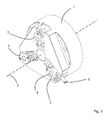
- the chuck 1 In the relative position of the chuck 1 and the jaw exchanging device 11 that is shown in figure 5 , the chuck 1 has been rotated about the central axis 2, so that a jaw connecting element 3 is located at the upper side of the chuck 1 and the operating pin 5 thereof extends in vertical direction.
- the jaw exchanging device 2 has been moved and rotated about a vertical axis, for example by means of a robot, so that the checking device 16 is positioned opposite the jaw connecting element 3.
- the laser of the checking device 16 it is checked whether no jaw 17 is present on the jaw connecting element 3. It is also checked whether the locking element 4 is in the releasing position. This can for example be done on the basis of the position of the operating pin 5.
- the jaw exchanging device 11 will be rotated about the vertical axis until the cleaning element 15 is positioned opposite the jaw connecting element 3.
- the jaw connecting element 3 is cleaned by means of the brush, which is rotatable about an axis that extends parallel to the central axis 2.
- Said cleaning step may involve movement only of the cleaning element 15 or of the entire jaw exchanging device 11 relative to the jaw connecting element 3, so that the entire outer side thereof can be adequately cleaned (see figure 6 ).
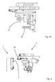
- FIG 7 a next step is shown, in which the jaw exchanging device 11 has again been rotated so far about the vertical axis that the grippers 12 are now positioned opposite the jaw connecting element 3. A jaw 17 is clamped between the grippers 12.
- the jaw 17 is shown to have been positioned opposite the jaw connecting element 3 with an engaging edge 18 thereof by means of the grippers 12.
- the engaging edge 18 is now positioned opposite a side of the jaw connecting element 3 that is located on the outer side of the chuck 1.
- the connecting element 13 can be moved independently of the grippers 12 and the connecting element 13 has been connected to the operating pin 5 in the step shown in figure 8 , in which the strip 14 has been brought into engagement with the slot 9 in the operating pin 5.
- the locking element 4 is in the releasing position.
- the strip 14 is being slit in the slot 9, so that by placing the strip 14 in the slot 9, possible dirt present in the slot 9 will be slit out of the slot 9.
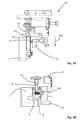
- the jaw exchanging device 11 is shown to have moved the grippers 12 with the jaw 17 in the direction indicated by the arrow P3, bringing the jaw 17 into engagement with the jaw connecting element 3.
- the connecting element 13 is then rotated in the direction indicated by the arrow P1, as a result of which the operating pin 5 connected thereto is rotated as well and the locking element 4 is moved from the releasing position to the locking position.
- the locking element 4 is located in an opening 19 provided in the jaw 17 for that purpose.
- the grippers 12 are then opened, whereupon a next jaw is picked up from a magazine by means of the jaw exchanging device 11.
- the chuck 1 is rotated through 120 degrees about the central axis, after which a second jaw and then a third jaw 17 are connected to the chuck 1 by carrying out the steps indicated in figures 5-9B .
- Removing the jaws 17 takes place in a comparable manner, wherein the orientation of the chuck 1 is checked, the jaw 17 is gripped, the locking element 4 is released and the jaw 17 is removed.
Landscapes
- Engineering & Computer Science (AREA)
- Mechanical Engineering (AREA)
- Gripping On Spindles (AREA)
- Clamps And Clips (AREA)
Applications Claiming Priority (1)
| Application Number | Priority Date | Filing Date | Title |
|---|---|---|---|
| NL2003802A NL2003802C2 (nl) | 2009-11-16 | 2009-11-16 | Systeem alsmede bewerkingsinrichting, klauwplaat,klauw-koppelelement, klauw-wisselinrichting en werkwijze. |
Publications (1)
| Publication Number | Publication Date |
|---|---|
| EP2322302A1 true EP2322302A1 (de) | 2011-05-18 |
Family
ID=42246134
Family Applications (1)
| Application Number | Title | Priority Date | Filing Date |
|---|---|---|---|
| EP10190631A Withdrawn EP2322302A1 (de) | 2009-11-16 | 2010-11-10 | System mit einer Bearbeitungsmaschine, einem Spannfutter, einem Eelement zum Verbinden einer Spannbacke, einem Spannbackenwechselgerät sowie Verfahren dazu |
Country Status (4)
| Country | Link |
|---|---|
| US (1) | US8545374B2 (de) |
| EP (1) | EP2322302A1 (de) |
| CA (1) | CA2720514A1 (de) |
| NL (1) | NL2003802C2 (de) |
Families Citing this family (8)
| Publication number | Priority date | Publication date | Assignee | Title |
|---|---|---|---|---|
| JP7087505B2 (ja) * | 2018-03-19 | 2022-06-21 | 豊和工業株式会社 | チャックの爪交換用ハンド、チャックの爪自動交換方法及び爪自動交換システム |
| JP6655222B1 (ja) | 2019-08-29 | 2020-02-26 | ヤマザキマザック株式会社 | ジョー交換装置、および、工作機械 |
| US11154993B2 (en) | 2019-12-11 | 2021-10-26 | Delaware Capital Formation, Inc. | Tool changer |
| JP6935570B1 (ja) * | 2020-10-29 | 2021-09-15 | 株式会社北川鉄工所 | 治具自動交換システム |
| US12240073B2 (en) | 2021-09-29 | 2025-03-04 | Stabilus Motion Controls Gmbh | Tool changer |
| CN120901738B (zh) * | 2025-10-09 | 2025-12-30 | 南通泽铭精密机械有限公司 | 一种车铣复合加工中心用零件固定装置 |
| CN121468228B (zh) * | 2026-01-08 | 2026-03-31 | 济南章力机械有限公司 | 一种数控加工中心的工装夹具 |
| CN121715820B (zh) * | 2026-02-11 | 2026-04-17 | 中北大学 | 一种通用化产品装配平台 |
Citations (7)
| Publication number | Priority date | Publication date | Assignee | Title |
|---|---|---|---|---|
| JPS5947106A (ja) * | 1982-09-05 | 1984-03-16 | Hitachi Seiki Co Ltd | 工作機械のチヤツク爪自動交換装置 |
| US4644636A (en) * | 1985-01-17 | 1987-02-24 | Index-Werke Komm.-Ges. Hahn & Tessky | Device for changing chuck attachment jaws |
| JPS634246U (de) * | 1986-06-27 | 1988-01-12 | ||
| EP1849556A1 (de) * | 2006-04-27 | 2007-10-31 | System 3R International AB | Spannvorrichtung mit Einrichtung zur Messung der Distanz zwischen einem Spannfutter und einem Werkzeug- oder Werkstückhalter |
| US20080217871A1 (en) * | 2005-07-04 | 2008-09-11 | Forkardt Deutschland Gmbh | Implement Clamping System, a Base Jaw and Top Jaw for It |
| EP2065110A1 (de) * | 2007-11-29 | 2009-06-03 | Yamazaki Mazak Corporation | Automatisches Futterklemmentauschsystem in einer kombinierten Bearbeitungsdrehbank |
| FR2956993A1 (fr) * | 2010-03-04 | 2011-09-09 | Ind Dev Etude Construction | Procede de reglage automatique d'un mandrin de machine outil |
Family Cites Families (7)
| Publication number | Priority date | Publication date | Assignee | Title |
|---|---|---|---|---|
| GB8327294D0 (en) * | 1983-10-12 | 1983-11-16 | Pratt Int Ltd Burnerd | Jaw changing apparatus |
| IT1161513B (it) * | 1983-10-13 | 1987-03-18 | Pinto Spa Mario | Mandrino autocentrante con griffe regolabili e sostituibili |
| JPS60255302A (ja) * | 1984-05-29 | 1985-12-17 | Kitagawa Tekkosho:Kk | 工作機のチヤツク爪自動交換装置 |
| DE3603459A1 (de) * | 1986-02-05 | 1987-08-06 | Smw Spanneinrichtungen | Einrichtung zur koppelung eines aufsatzspannbackens mit einem grundbacken eines spannfutters |
| FR2623431B1 (fr) * | 1987-11-24 | 1994-04-29 | Gamet Precision | Mandrin de serrage pour machine-outil |
| DE4016775C1 (de) * | 1990-05-25 | 1991-04-18 | Paul Forkardt Gmbh & Co Kg, 4000 Duesseldorf, De | |
| US7594665B2 (en) * | 2007-02-27 | 2009-09-29 | Illinois Tool Works Inc. | Quick-release jaws with a single-piece bearing chuck |
-
2009
- 2009-11-16 NL NL2003802A patent/NL2003802C2/nl not_active IP Right Cessation
-
2010
- 2010-11-09 CA CA2720514A patent/CA2720514A1/en not_active Abandoned
- 2010-11-10 EP EP10190631A patent/EP2322302A1/de not_active Withdrawn
- 2010-11-16 US US12/947,596 patent/US8545374B2/en not_active Expired - Fee Related
Patent Citations (8)
| Publication number | Priority date | Publication date | Assignee | Title |
|---|---|---|---|---|
| JPS5947106A (ja) * | 1982-09-05 | 1984-03-16 | Hitachi Seiki Co Ltd | 工作機械のチヤツク爪自動交換装置 |
| US4644636A (en) * | 1985-01-17 | 1987-02-24 | Index-Werke Komm.-Ges. Hahn & Tessky | Device for changing chuck attachment jaws |
| JPS634246U (de) * | 1986-06-27 | 1988-01-12 | ||
| US20080217871A1 (en) * | 2005-07-04 | 2008-09-11 | Forkardt Deutschland Gmbh | Implement Clamping System, a Base Jaw and Top Jaw for It |
| EP1899099B1 (de) | 2005-07-04 | 2008-09-17 | Forkardt Deutschland GmbH | Geräteeinspannsystem sowie untere und obere klemmbacke dafür |
| EP1849556A1 (de) * | 2006-04-27 | 2007-10-31 | System 3R International AB | Spannvorrichtung mit Einrichtung zur Messung der Distanz zwischen einem Spannfutter und einem Werkzeug- oder Werkstückhalter |
| EP2065110A1 (de) * | 2007-11-29 | 2009-06-03 | Yamazaki Mazak Corporation | Automatisches Futterklemmentauschsystem in einer kombinierten Bearbeitungsdrehbank |
| FR2956993A1 (fr) * | 2010-03-04 | 2011-09-09 | Ind Dev Etude Construction | Procede de reglage automatique d'un mandrin de machine outil |
Also Published As
| Publication number | Publication date |
|---|---|
| NL2003802C2 (nl) | 2011-05-17 |
| US8545374B2 (en) | 2013-10-01 |
| CA2720514A1 (en) | 2011-05-16 |
| US20110115171A1 (en) | 2011-05-19 |
Similar Documents
| Publication | Publication Date | Title |
|---|---|---|
| EP2322302A1 (de) | System mit einer Bearbeitungsmaschine, einem Spannfutter, einem Eelement zum Verbinden einer Spannbacke, einem Spannbackenwechselgerät sowie Verfahren dazu | |
| JP6118597B2 (ja) | 電線端処理装置 | |
| JP6259462B2 (ja) | チャック装置及び部品装着機 | |
| US20100071203A1 (en) | Crimping machine for different crimping and pressing processes, in particular for cable assembly | |
| CN111655436A (zh) | 用于在不同位置之间传送夹紧装置的卡接定位装置 | |
| US10143089B2 (en) | Printing system with first and second pairs of slide elements | |
| EP3689564B1 (de) | Werkzeugwechselsystem für plotter | |
| TWI699249B (zh) | 夾台之爪交換用把手、夾台之爪自動交換方法及爪自動交換系統 | |
| DE102019102212A1 (de) | Reifengreifer | |
| US8745862B2 (en) | Method for drilling reference bores into printed circuit boards | |
| EP3064325B1 (de) | Greifer für einen roboter und zugehöriger roboter | |
| JP2014176866A (ja) | リベット挿入装置 | |
| CN106671118A (zh) | 一种光学滤光片的抓取装置、抓取方法及定位工装 | |
| US10814450B2 (en) | Processes for fitting cable bushings | |
| EP3646415B1 (de) | Vorrichtung zur kabelverarbeitung | |
| CN108156800B (zh) | 装夹系统及其取料装置及电子元件与电路板的插装方法 | |
| RS58886B1 (sr) | Sklop hvatača i postupak za hvatanje komponente pneumatika | |
| KR102466780B1 (ko) | 와이어 싱귤레이션 장치를 갖는 와이어 전달 시스템 | |
| WO2023237218A1 (de) | Fertigungssystem und verfahren zur bearbeitung eines werkstücks | |
| TW202019590A (zh) | 夾台的抓握精度確認方法、夾台的爪交換方法及夾台的抓握精度確認裝置 | |
| TWI715273B (zh) | 夾頭的爪的連結機構 | |
| CN218341018U (zh) | 一种适用于短管状零件两端面倒角的加工装置 | |
| KR101654536B1 (ko) | Pcb용 단자 이송 및 삽입장치 | |
| JP7492773B2 (ja) | 2つのクランプ装置間で被加工物を再クランプするための再クランプ装置及び方法 | |
| EP4147818B1 (de) | Spannvorrichtung |
Legal Events
| Date | Code | Title | Description |
|---|---|---|---|
| PUAI | Public reference made under article 153(3) epc to a published international application that has entered the european phase |
Free format text: ORIGINAL CODE: 0009012 |
|
| AK | Designated contracting states |
Kind code of ref document: A1 Designated state(s): AL AT BE BG CH CY CZ DE DK EE ES FI FR GB GR HR HU IE IS IT LI LT LU LV MC MK MT NL NO PL PT RO RS SE SI SK SM TR |
|
| AX | Request for extension of the european patent |
Extension state: BA ME |
|
| 17P | Request for examination filed |
Effective date: 20111116 |
|
| 17Q | First examination report despatched |
Effective date: 20161014 |
|
| STAA | Information on the status of an ep patent application or granted ep patent |
Free format text: STATUS: EXAMINATION IS IN PROGRESS |
|
| STAA | Information on the status of an ep patent application or granted ep patent |
Free format text: STATUS: THE APPLICATION IS DEEMED TO BE WITHDRAWN |
|
| 18D | Application deemed to be withdrawn |
Effective date: 20170225 |