EP2322761A2 - Turbinenschaufel und Rotor - Google Patents
Turbinenschaufel und Rotor Download PDFInfo
- Publication number
- EP2322761A2 EP2322761A2 EP10190223A EP10190223A EP2322761A2 EP 2322761 A2 EP2322761 A2 EP 2322761A2 EP 10190223 A EP10190223 A EP 10190223A EP 10190223 A EP10190223 A EP 10190223A EP 2322761 A2 EP2322761 A2 EP 2322761A2
- Authority
- EP
- European Patent Office
- Prior art keywords
- elongate
- vane
- elongate vane
- turbine blade
- longitudinal axis
- Prior art date
- Legal status (The legal status is an assumption and is not a legal conclusion. Google has not performed a legal analysis and makes no representation as to the accuracy of the status listed.)
- Granted
Links
Images




Classifications
-
- F—MECHANICAL ENGINEERING; LIGHTING; HEATING; WEAPONS; BLASTING
- F01—MACHINES OR ENGINES IN GENERAL; ENGINE PLANTS IN GENERAL; STEAM ENGINES
- F01D—NON-POSITIVE DISPLACEMENT MACHINES OR ENGINES, e.g. STEAM TURBINES
- F01D5/00—Blades; Blade-carrying members; Heating, heat-insulating, cooling or antivibration means on the blades or the members
- F01D5/30—Fixing blades to rotors; Blade roots ; Blade spacers
- F01D5/3007—Fixing blades to rotors; Blade roots ; Blade spacers of axial insertion type
-
- F—MECHANICAL ENGINEERING; LIGHTING; HEATING; WEAPONS; BLASTING
- F01—MACHINES OR ENGINES IN GENERAL; ENGINE PLANTS IN GENERAL; STEAM ENGINES
- F01D—NON-POSITIVE DISPLACEMENT MACHINES OR ENGINES, e.g. STEAM TURBINES
- F01D5/00—Blades; Blade-carrying members; Heating, heat-insulating, cooling or antivibration means on the blades or the members
- F01D5/12—Blades
- F01D5/14—Form or construction
- F01D5/16—Form or construction for counteracting blade vibration
-
- F—MECHANICAL ENGINEERING; LIGHTING; HEATING; WEAPONS; BLASTING
- F01—MACHINES OR ENGINES IN GENERAL; ENGINE PLANTS IN GENERAL; STEAM ENGINES
- F01D—NON-POSITIVE DISPLACEMENT MACHINES OR ENGINES, e.g. STEAM TURBINES
- F01D5/00—Blades; Blade-carrying members; Heating, heat-insulating, cooling or antivibration means on the blades or the members
- F01D5/12—Blades
- F01D5/22—Blade-to-blade connections, e.g. for damping vibrations
- F01D5/225—Blade-to-blade connections, e.g. for damping vibrations by shrouding
-
- F—MECHANICAL ENGINEERING; LIGHTING; HEATING; WEAPONS; BLASTING
- F05—INDEXING SCHEMES RELATING TO ENGINES OR PUMPS IN VARIOUS SUBCLASSES OF CLASSES F01-F04
- F05B—INDEXING SCHEME RELATING TO WIND, SPRING, WEIGHT, INERTIA OR LIKE MOTORS, TO MACHINES OR ENGINES FOR LIQUIDS COVERED BY SUBCLASSES F03B, F03D AND F03G
- F05B2240/00—Components
- F05B2240/20—Rotors
- F05B2240/33—Shrouds which are part of or which are rotating with the rotor
-
- F—MECHANICAL ENGINEERING; LIGHTING; HEATING; WEAPONS; BLASTING
- F05—INDEXING SCHEMES RELATING TO ENGINES OR PUMPS IN VARIOUS SUBCLASSES OF CLASSES F01-F04
- F05D—INDEXING SCHEME FOR ASPECTS RELATING TO NON-POSITIVE-DISPLACEMENT MACHINES OR ENGINES, GAS-TURBINES OR JET-PROPULSION PLANTS
- F05D2240/00—Components
- F05D2240/80—Platforms for stationary or moving blades
-
- F—MECHANICAL ENGINEERING; LIGHTING; HEATING; WEAPONS; BLASTING
- F05—INDEXING SCHEMES RELATING TO ENGINES OR PUMPS IN VARIOUS SUBCLASSES OF CLASSES F01-F04
- F05D—INDEXING SCHEME FOR ASPECTS RELATING TO NON-POSITIVE-DISPLACEMENT MACHINES OR ENGINES, GAS-TURBINES OR JET-PROPULSION PLANTS
- F05D2260/00—Function
- F05D2260/96—Preventing, counteracting or reducing vibration or noise
Definitions
- Embodiments of the invention relate generally to turbine blades and rotors and, more particularly, to turbine blades having, among other features, complimentarily shaped integral covers and bases capable of increasing stiffness and damping characteristics while decreasing vibratory stress.
- Turbine blades particularly those operating at high speeds and/or experiencing high loads, are subject to stresses, including vibratory stress, that can reduce the overall efficiency of the turbine, shorten the life of the turbine blades or other rotor components, and, in some cases, lead to failure of the turbine blade itself and/or other rotor components.
- turbine blades exhibiting improved stiffness or damping characteristics, or subject to decreased vibratory stress are generally capable of operating at higher speeds and/or bearing higher loads, and exhibit improved efficiency and increased life.
- the invention provides a turbine blade comprising: an elongate vane having a twisted configuration about a longitudinal axis, the elongate vane having a leading face and a trailing face; a base at a proximal end of the elongate vane, the base having: a substantially planar member substantially normal to the longitudinal axis of the elongate vane; a protrusion at a trailing face of the planar member, the protrusion supporting a portion of the proximal end of the elongate vane; a relief at a leading face of the planar member, a shape of the relief being substantially complimentary to a shape of the protrusion; and a dovetail member on a surface of the planar member opposite the elongate vane; and a cover member at a distal end of the elongate vane, the cover member being substantially normal to the longitudinal axis of the elongate vane and having a leading face and a trailing face, the shapes
- Still another embodiment of the invention provides a rotor comprising: a rotor wheel having a plurality of axially-oriented dovetail openings; a plurality of turbine blades, each turbine blade having: an elongate vane having a twisted configuration about a longitudinal axis thereof; a base at a proximal end of the elongate vane, the base having: a substantially planar member substantially normal to the longitudinal axis of the elongate vane; and a dovetail member on a surface of the planar member opposite the elongate vane, a shape of the dovetail member being complimentary to a shape of the at least one of the plurality of axially-oriented dovetail openings; and a cover member at a distal end of the elongate vane, the cover member being substantially normal to the longitudinal axis of the elongate vane and having a leading face and a trailing face, the shapes of the leading and trailing faces being substantially complimentary.
- FIG 1 shows a perspective view of a turbine blade 100 according to an embodiment of the invention.
- Turbine blade 100 includes an elongate vane 10 having a twisted configuration about its longitudinal axis 12, a base 30 at the proximal end 13 of elongate vane 10, a dovetail member 40 for mating turbine blade 100 with a rotor wheel (not shown), and an integrated cover 60 at the distal end 19 of vane 10.
- the term "twisted,” when used in describing a configuration of elongate vane 10, is meant to refer to an unequal bending, turning, or wrapping of elongate vane 10 along its radial height 80. That is, as shown in FIG. 1 , distal end 19 of elongate vane 10 is turned or wrapped about longitudinal axis 12 to a greater degree than is proximal end 13.
- a substantially planar member 32 is oriented substantially normal to longitudinal axis 12 of elongate vane 10. That is, while a surface of planar member 32 may include a slightly arcuate shape in order to accommodate its insertion into a rotor wheel (described in greater detail below), the surface at which it meets elongate vane 10 is substantially planar, such that longitudinal axis 12 of elongate vane 10 forms an angle of about 90 degrees with planar member 32.
- Cover 60 is oriented such that its longitudinal axis 66 is substantially perpendicular to longitudinal axis 12 of elongate vane 10.
- vane 10 In operation, turbine blade 100 travels in direction A.
- vane 10 includes a leading face 14 and a trailing face 16.
- Base 30 includes substantially planar member 32 having a leading face 35 and a trailing face 33, and cover 60 includes a leading face 62 and a trailing face 64.
- leading face 14 of elongate vane 10 is flame-hardened.
- Planar member 32 includes a relief 36 or fillet along its leading face 35 and a complimentarily-shaped protrusion 34 along its trailing face 33, such that (as will be described in greater detail below) adjacent turbine blades 100 form a tied-in edge.
- Beneath planar member 32, as noted above, dovetail member 40 facilitates mating blade 100 with a rotor wheel.
- Hooks 42, 44, 46 have shapes complimentary to axially-oriented dovetail openings in the rotor wheel. In operation, hooks 42, 44, 46 serve to transmit the rotor load from blade 100 to the rotor wheel in a known fashion.
- dovetail member 40 is shown in FIG 1 as having three hooks 42, 44, 46, this is not essential. Any number of hooks may be employed. Similarly, while hooks 42, 44, 46 are shown having similar shapes of different sizes, this also is not essential. That is, hooks 42, 44, 46 may have different shapes and/or be of similar sizes. In such cases, axially-oriented dovetail openings in the rotor wheel are of complimentary shapes and sizes.
- FIG. 2 shows a top-down view of turbine blade 100.
- Leading face 62 of cover 60 is shown having a notch 62A, the shape of which is substantially complimentary to a point 64A of trailing face 64.
- a pair of blades 100 when installed in adjacent positions in a rotor wheel, exhibit an interference fit (described in greater detail below) between a trailing face 64 of one blade and a leading face 62 of the adjacent blade.
- cover 60 of each blade 100 turns in direction B, increasing the interference.
- FIG 3 shows a side elevational view two turbine blades 200, 300, positioned substantially as they would be when installed in adjacent positions of a rotor wheel (not shown).
- protrusion 334 of turbine blade 300 covers the relief (obscured) of turbine blade 200.
- the protrusion of an additional turbine blade if installed adjacent turbine blade 300 (i.e., on a side of turbine blade 300 opposite turbine blade 200), would cover relief 336 of turbine blade 300.
- leading face 262 of turbine blade 200 forms an interference fit 390 with trailing face 364 of turbine blade 300.
- this interference fit provides a continuous coupling of the blades, resulting in superior stiffness, superior damping characteristics, and low vibratory stress, when compared to "free-standing" designs lacking such interference.
- vanes 210, 310 will deform, i.e., they will "untwist" about their longitudinal axes 212, 312, respectively.
- cover 260 of turbine blade 200 will move in direction C (i.e., about longitudinal axis 212 in a direction opposite the twisting of vane 210) and cover 360 of turbine blade 300 will move in direction D (i.e., about longitudinal axis 312 in a direction opposite the twisting of vane 310), thereby increasing interference fit 390, resulting in increased stiffness and damping and decreasing vibratory stress in the assembled rotor.
- FIG 4 a partial side elevational view of turbine blade 100 of FIG 1 is shown.
- a plurality 70 of longitudinal grooves 72, 74, 76 is disposed along leading face 14 of vane 10.
- Longitudinal grooves 72, 74, 76 act to remove moisture which may form on leading face 14 during operation.
- Each longitudinal groove 72, 74, 76 includes a first end 72A, 74A, 76A positioned between about one-third and about one-half the radial height 80 ( FIG 1 ) of vane 10, as measured from the distal end 19 of vane 30, and a second end 72B, 74B, 76B at distal end 19 of vane 30.
- longitudinal grooves 72, 74, 76 cover between about one-third and about one-half the radial height 80 of vane 10. In some embodiments, longitudinal grooves 72, 74, 76 cover about 40% of radial height 80 of vane 10. As noted above, leading face 14 may be flame-hardened. Similarly, longitudinal grooves 72, 74, 76 may be flame-hardened, which acts to prevent erosion as moisture is removed from leading face 14.
- the plurality 70 of longitudinal grooves 72, 74, 76 is disposed nearer the leading edge 15 than the trailing edge 17 of vane 10. As such, second ends 72B, 74B, 76B of longitudinal grooves 72, 74, 76 are preferably not obscured by cover 60, which would impede the removal of moisture from leading face 14.
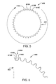
- FIGS. 5 and 6 show full and partial side cross-sectional views, respectively, of a rotor wheel 400 according to an embodiment of the invention.
- rotor wheel 400 includes a circular rotor body 402 and a plurality of axially-oriented dovetail openings 410A, 410B, 410C...410n positioned about its circumference.
- Each of the axially-oriented dovetail openings 410A, 410B, 410C...410n has a shape complimentary to dovetail member 40 ( FIG. 1 ) of turbine blade 100, permitting axial insertion of turbine blade 100 into, for example, axially-oriented dovetail opening 410A.
- FIG 6 shows a more detailed view of a portion of rotor wheel 400.
- Axially-oriented dovetail opening 410A includes a plurality of slots 412A, 414A, 416A having shapes complimentary to hooks 42, 44, 46 of dovetail member 40 of turbine blade 100 ( FIG. 1 ).
- the number of axially-oriented dovetail openings 410A, 410B, 410C...410n shown is merely illustrative.
- a rotor wheel according to the invention may include any number of such axially-oriented dovetail openings.
- axially-oriented dovetail openings may have different shapes, as long as each is complimentary to a corresponding dovetail member of a turbine blade, such that the turbine blade may be fully installed into the rotor wheel.
Landscapes
- Engineering & Computer Science (AREA)
- Mechanical Engineering (AREA)
- General Engineering & Computer Science (AREA)
- Turbine Rotor Nozzle Sealing (AREA)
Applications Claiming Priority (1)
| Application Number | Priority Date | Filing Date | Title |
|---|---|---|---|
| US12/617,683 US8277189B2 (en) | 2009-11-12 | 2009-11-12 | Turbine blade and rotor |
Publications (3)
| Publication Number | Publication Date |
|---|---|
| EP2322761A2 true EP2322761A2 (de) | 2011-05-18 |
| EP2322761A3 EP2322761A3 (de) | 2013-10-09 |
| EP2322761B1 EP2322761B1 (de) | 2021-03-03 |
Family
ID=43567794
Family Applications (1)
| Application Number | Title | Priority Date | Filing Date |
|---|---|---|---|
| EP10190223.7A Active EP2322761B1 (de) | 2009-11-12 | 2010-11-05 | Beschaufeltes rotorrad |
Country Status (4)
| Country | Link |
|---|---|
| US (1) | US8277189B2 (de) |
| EP (1) | EP2322761B1 (de) |
| JP (1) | JP2011106449A (de) |
| RU (1) | RU2547128C2 (de) |
Cited By (3)
| Publication number | Priority date | Publication date | Assignee | Title |
|---|---|---|---|---|
| EP2527596A4 (de) * | 2010-01-20 | 2013-07-31 | Mitsubishi Heavy Ind Ltd | Turbinenrotorblatt und turbomaschine |
| WO2014025729A1 (en) * | 2012-08-07 | 2014-02-13 | General Electric Company | Last stage turbine blade including a plurality of leading edge indentations, corresponding rotor assembly and steam turbine |
| EP2918784A1 (de) * | 2014-03-13 | 2015-09-16 | Siemens Aktiengesellschaft | Schaufelfuß für eine Turbinenschaufel |
Families Citing this family (6)
| Publication number | Priority date | Publication date | Assignee | Title |
|---|---|---|---|---|
| US8888459B2 (en) * | 2011-08-23 | 2014-11-18 | General Electric Company | Coupled blade platforms and methods of sealing |
| US9909425B2 (en) | 2011-10-31 | 2018-03-06 | Pratt & Whitney Canada Corporation | Blade for a gas turbine engine |
| CA146333S (en) * | 2012-02-02 | 2013-02-07 | Novenco As | Ventilator blade |
| EP2669477B1 (de) * | 2012-05-31 | 2017-04-05 | General Electric Technology GmbH | Deckplatte für Schaufeln |
| US9581170B2 (en) * | 2013-03-15 | 2017-02-28 | Honeywell International Inc. | Methods of designing and making diffuser vanes in a centrifugal compressor |
| US20180179952A1 (en) * | 2016-12-23 | 2018-06-28 | General Electric Company | Rotating detonation engine and method of operating same |
Family Cites Families (34)
| Publication number | Priority date | Publication date | Assignee | Title |
|---|---|---|---|---|
| CA903091A (en) * | 1972-06-20 | P. Zeman Kenneth | Tie pins for turbine buckets | |
| US3304056A (en) * | 1965-03-19 | 1967-02-14 | Hitachi Ltd | Turbine blades |
| US4155152A (en) * | 1977-12-12 | 1979-05-22 | Matthew Bernardo | Method of restoring the shrouds of turbine blades |
| JPS54136404U (de) * | 1978-03-17 | 1979-09-21 | ||
| JPS5578103A (en) * | 1978-12-08 | 1980-06-12 | Hitachi Ltd | Method of implanting movable turbine blade |
| JPS6018202U (ja) * | 1983-07-15 | 1985-02-07 | 株式会社東芝 | タ−ボ流体機械の羽根 |
| JPS637202U (de) * | 1986-07-01 | 1988-01-18 | ||
| US4714410A (en) * | 1986-08-18 | 1987-12-22 | Westinghouse Electric Corp. | Trailing edge support for control stage steam turbine blade |
| US4815938A (en) * | 1987-12-24 | 1989-03-28 | Westinghouse Electric Corp. | Shroud gap control for integral shrouded blades |
| JP2604448Y2 (ja) * | 1991-04-22 | 2000-05-15 | 三菱重工業株式会社 | 回転翼 |
| US5277549A (en) * | 1992-03-16 | 1994-01-11 | Westinghouse Electric Corp. | Controlled reaction L-2R steam turbine blade |
| US5267834A (en) * | 1992-12-30 | 1993-12-07 | General Electric Company | Bucket for the last stage of a steam turbine |
| US5351395A (en) * | 1992-12-30 | 1994-10-04 | General Electric Company | Process for producing turbine bucket with water droplet erosion protection |
| US5480285A (en) * | 1993-08-23 | 1996-01-02 | Westinghouse Electric Corporation | Steam turbine blade |
| JPH08225828A (ja) * | 1995-02-15 | 1996-09-03 | Toshiba Corp | 蒸気タービン動翼のフレームハードニング装置及びフレームハードニング方法 |
| JPH10299405A (ja) * | 1997-04-28 | 1998-11-10 | Toshiba Corp | タービン動翼およびその組み立て工法 |
| JPH11159302A (ja) * | 1997-11-25 | 1999-06-15 | Hitachi Ltd | 蒸気タービン動翼 |
| JP4051132B2 (ja) * | 1998-05-25 | 2008-02-20 | 株式会社東芝 | タービン動翼 |
| US6030178A (en) * | 1998-09-14 | 2000-02-29 | General Electric Co. | Axial entry dovetail segment for securing a closure bucket to a turbine wheel and methods of installation |
| JP3793667B2 (ja) * | 1999-07-09 | 2006-07-05 | 株式会社日立製作所 | 低圧蒸気タービン最終段動翼の製造方法 |
| DE10014189A1 (de) * | 2000-03-23 | 2001-09-27 | Alstom Power Nv | Befestigung der Beschaufelung einer Strömungsmaschine |
| US6491498B1 (en) * | 2001-10-04 | 2002-12-10 | Power Systems Mfg, Llc. | Turbine blade pocket shroud |
| US6877956B2 (en) * | 2002-12-23 | 2005-04-12 | General Electric Company | Methods and apparatus for integral radial leakage seal |
| US7318699B2 (en) * | 2005-05-31 | 2008-01-15 | General Electric Company | Moisture removal grooves on steam turbine buckets and covers and methods of manufacture |
| JP4673732B2 (ja) * | 2005-12-01 | 2011-04-20 | 株式会社東芝 | タービン動翼および蒸気タービン |
| JP2007332893A (ja) * | 2006-06-16 | 2007-12-27 | Mitsubishi Heavy Ind Ltd | 軸流タービン翼の制振及びフレッティング防止構造 |
| JP5025241B2 (ja) * | 2006-12-01 | 2012-09-12 | 株式会社東芝 | タービン動翼および蒸気タービン |
| US8038404B2 (en) * | 2007-07-16 | 2011-10-18 | Nuovo Pignone Holdings, S.P.A. | Steam turbine and rotating blade |
| US7946823B2 (en) * | 2007-07-16 | 2011-05-24 | Nuovo Pignone Holdings, S.P.A. | Steam turbine rotating blade |
| JP4991663B2 (ja) * | 2007-09-11 | 2012-08-01 | 株式会社日立製作所 | 蒸気タービン動翼組立体 |
| US8047796B2 (en) * | 2007-11-16 | 2011-11-01 | General Electric Company | Dovetail attachment for use with turbine assemblies and methods of assembling turbine assemblies |
| US7901523B2 (en) * | 2007-11-16 | 2011-03-08 | General Electric Company | Uniform heat treatment process for hardening steel |
| JP2010053822A (ja) * | 2008-08-29 | 2010-03-11 | Toshiba Corp | タービン動翼および蒸気タービン |
| US8052393B2 (en) * | 2008-09-08 | 2011-11-08 | General Electric Company | Steam turbine rotating blade for a low pressure section of a steam turbine engine |
-
2009
- 2009-11-12 US US12/617,683 patent/US8277189B2/en active Active
-
2010
- 2010-11-05 EP EP10190223.7A patent/EP2322761B1/de active Active
- 2010-11-09 JP JP2010250380A patent/JP2011106449A/ja active Pending
- 2010-11-11 RU RU2010145978/06A patent/RU2547128C2/ru not_active IP Right Cessation
Non-Patent Citations (1)
| Title |
|---|
| None |
Cited By (5)
| Publication number | Priority date | Publication date | Assignee | Title |
|---|---|---|---|---|
| EP2527596A4 (de) * | 2010-01-20 | 2013-07-31 | Mitsubishi Heavy Ind Ltd | Turbinenrotorblatt und turbomaschine |
| US9194239B2 (en) | 2010-01-20 | 2015-11-24 | Mitsubishi Heavy Industries, Ltd. | Turbine rotor blade and turbo machine |
| WO2014025729A1 (en) * | 2012-08-07 | 2014-02-13 | General Electric Company | Last stage turbine blade including a plurality of leading edge indentations, corresponding rotor assembly and steam turbine |
| CN104755704A (zh) * | 2012-08-07 | 2015-07-01 | 通用电气公司 | 包括多个前缘凹痕的末级涡轮叶片、对应的转子组件和蒸汽涡轮 |
| EP2918784A1 (de) * | 2014-03-13 | 2015-09-16 | Siemens Aktiengesellschaft | Schaufelfuß für eine Turbinenschaufel |
Also Published As
| Publication number | Publication date |
|---|---|
| EP2322761B1 (de) | 2021-03-03 |
| JP2011106449A (ja) | 2011-06-02 |
| RU2547128C2 (ru) | 2015-04-10 |
| US8277189B2 (en) | 2012-10-02 |
| EP2322761A3 (de) | 2013-10-09 |
| US20110110784A1 (en) | 2011-05-12 |
| RU2010145978A (ru) | 2012-05-20 |
Similar Documents
| Publication | Publication Date | Title |
|---|---|---|
| EP2322761A2 (de) | Turbinenschaufel und Rotor | |
| WO2013130570A1 (en) | Turbine engine rotor blade groove | |
| US8651820B2 (en) | Dovetail connection for turbine rotating blade and rotor wheel | |
| EP3093439B1 (de) | Dämpfersystem für eine turbine | |
| JP4869616B2 (ja) | 蒸気タービン動翼と蒸気タービンロータ及びそれを用いた蒸気タービン並びにその発電プラント | |
| CA2880602C (en) | Shrouded blade for a gas turbine engine | |
| EP2951395B1 (de) | Turbomaschinen-rotorschaufel, turbomaschinen-rotorscheibe, turbomaschinenrotor und gasturbinenmotor mit unterschiedlichen kontaktflächenwinkeln des schaufelfusses und der schaufelnut | |
| US7841833B2 (en) | Turbine rotor and turbine blade | |
| US9739159B2 (en) | Method and system for relieving turbine rotor blade dovetail stress | |
| WO2017209752A1 (en) | Asymmetric attachment system for a turbine blade | |
| CN102459819B (zh) | 用于轴流式涡轮机的动叶片和用于动叶片的装配装置 | |
| US11946390B2 (en) | Rotor blade and disc of rotating body | |
| US20050249599A1 (en) | Turbine and turbine blade | |
| US20170037734A1 (en) | Underplatform damping members and methods for turbocharger assemblies | |
| EP1849963A2 (de) | Geschachtelte Turbinenschaufelverschlussgruppe | |
| US7503751B2 (en) | Apparatus and method for attaching a rotor blade to a rotor | |
| US9151163B2 (en) | Turbomachine rotor disk | |
| JP6382115B2 (ja) | プレツイステッド翼用のシュラウド | |
| US20170241275A1 (en) | Turbine rotor blade | |
| KR20100019348A (ko) | 터빈 동익과 그 고정 구조 | |
| EP2997230B1 (de) | Tangentialer schaufelfusshals mit konischer form | |
| KR102734159B1 (ko) | 에어포일 프로파일 | |
| KR102737121B1 (ko) | 에어포일 프로파일 | |
| KR102737132B1 (ko) | 에어포일 프로파일 | |
| KR102734168B1 (ko) | 에어포일 프로파일 |
Legal Events
| Date | Code | Title | Description |
|---|---|---|---|
| PUAI | Public reference made under article 153(3) epc to a published international application that has entered the european phase |
Free format text: ORIGINAL CODE: 0009012 |
|
| AK | Designated contracting states |
Kind code of ref document: A2 Designated state(s): AL AT BE BG CH CY CZ DE DK EE ES FI FR GB GR HR HU IE IS IT LI LT LU LV MC MK MT NL NO PL PT RO RS SE SI SK SM TR |
|
| AX | Request for extension of the european patent |
Extension state: BA ME |
|
| RIC1 | Information provided on ipc code assigned before grant |
Ipc: F01D 5/22 20060101AFI20130604BHEP Ipc: F01D 5/16 20060101ALI20130604BHEP |
|
| PUAL | Search report despatched |
Free format text: ORIGINAL CODE: 0009013 |
|
| AK | Designated contracting states |
Kind code of ref document: A3 Designated state(s): AL AT BE BG CH CY CZ DE DK EE ES FI FR GB GR HR HU IE IS IT LI LT LU LV MC MK MT NL NO PL PT RO RS SE SI SK SM TR |
|
| AX | Request for extension of the european patent |
Extension state: BA ME |
|
| RIC1 | Information provided on ipc code assigned before grant |
Ipc: F01D 5/16 20060101ALI20130905BHEP Ipc: F01D 5/22 20060101AFI20130905BHEP |
|
| 17P | Request for examination filed |
Effective date: 20140409 |
|
| RBV | Designated contracting states (corrected) |
Designated state(s): AL AT BE BG CH CY CZ DE DK EE ES FI FR GB GR HR HU IE IS IT LI LT LU LV MC MK MT NL NO PL PT RO RS SE SI SK SM TR |
|
| STAA | Information on the status of an ep patent application or granted ep patent |
Free format text: STATUS: EXAMINATION IS IN PROGRESS |
|
| 17Q | First examination report despatched |
Effective date: 20180907 |
|
| REG | Reference to a national code |
Ref country code: DE Ref legal event code: R079 Ref document number: 602010066525 Country of ref document: DE Free format text: PREVIOUS MAIN CLASS: F01D0005220000 Ipc: F01D0005300000 |
|
| GRAP | Despatch of communication of intention to grant a patent |
Free format text: ORIGINAL CODE: EPIDOSNIGR1 |
|
| STAA | Information on the status of an ep patent application or granted ep patent |
Free format text: STATUS: GRANT OF PATENT IS INTENDED |
|
| RIC1 | Information provided on ipc code assigned before grant |
Ipc: F01D 5/22 20060101ALI20200903BHEP Ipc: F01D 5/30 20060101AFI20200903BHEP |
|
| INTG | Intention to grant announced |
Effective date: 20201005 |
|
| GRAS | Grant fee paid |
Free format text: ORIGINAL CODE: EPIDOSNIGR3 |
|
| GRAA | (expected) grant |
Free format text: ORIGINAL CODE: 0009210 |
|
| STAA | Information on the status of an ep patent application or granted ep patent |
Free format text: STATUS: THE PATENT HAS BEEN GRANTED |
|
| AK | Designated contracting states |
Kind code of ref document: B1 Designated state(s): AL AT BE BG CH CY CZ DE DK EE ES FI FR GB GR HR HU IE IS IT LI LT LU LV MC MK MT NL NO PL PT RO RS SE SI SK SM TR |
|
| REG | Reference to a national code |
Ref country code: GB Ref legal event code: FG4D |
|
| REG | Reference to a national code |
Ref country code: AT Ref legal event code: REF Ref document number: 1367407 Country of ref document: AT Kind code of ref document: T Effective date: 20210315 Ref country code: CH Ref legal event code: EP |
|
| REG | Reference to a national code |
Ref country code: DE Ref legal event code: R096 Ref document number: 602010066525 Country of ref document: DE |
|
| REG | Reference to a national code |
Ref country code: IE Ref legal event code: FG4D |
|
| REG | Reference to a national code |
Ref country code: LT Ref legal event code: MG9D |
|
| PG25 | Lapsed in a contracting state [announced via postgrant information from national office to epo] |
Ref country code: HR Free format text: LAPSE BECAUSE OF FAILURE TO SUBMIT A TRANSLATION OF THE DESCRIPTION OR TO PAY THE FEE WITHIN THE PRESCRIBED TIME-LIMIT Effective date: 20210303 Ref country code: FI Free format text: LAPSE BECAUSE OF FAILURE TO SUBMIT A TRANSLATION OF THE DESCRIPTION OR TO PAY THE FEE WITHIN THE PRESCRIBED TIME-LIMIT Effective date: 20210303 Ref country code: GR Free format text: LAPSE BECAUSE OF FAILURE TO SUBMIT A TRANSLATION OF THE DESCRIPTION OR TO PAY THE FEE WITHIN THE PRESCRIBED TIME-LIMIT Effective date: 20210604 Ref country code: LT Free format text: LAPSE BECAUSE OF FAILURE TO SUBMIT A TRANSLATION OF THE DESCRIPTION OR TO PAY THE FEE WITHIN THE PRESCRIBED TIME-LIMIT Effective date: 20210303 Ref country code: BG Free format text: LAPSE BECAUSE OF FAILURE TO SUBMIT A TRANSLATION OF THE DESCRIPTION OR TO PAY THE FEE WITHIN THE PRESCRIBED TIME-LIMIT Effective date: 20210603 Ref country code: NO Free format text: LAPSE BECAUSE OF FAILURE TO SUBMIT A TRANSLATION OF THE DESCRIPTION OR TO PAY THE FEE WITHIN THE PRESCRIBED TIME-LIMIT Effective date: 20210603 |
|
| REG | Reference to a national code |
Ref country code: NL Ref legal event code: MP Effective date: 20210303 |
|
| REG | Reference to a national code |
Ref country code: AT Ref legal event code: MK05 Ref document number: 1367407 Country of ref document: AT Kind code of ref document: T Effective date: 20210303 |
|
| PG25 | Lapsed in a contracting state [announced via postgrant information from national office to epo] |
Ref country code: SE Free format text: LAPSE BECAUSE OF FAILURE TO SUBMIT A TRANSLATION OF THE DESCRIPTION OR TO PAY THE FEE WITHIN THE PRESCRIBED TIME-LIMIT Effective date: 20210303 Ref country code: PL Free format text: LAPSE BECAUSE OF FAILURE TO SUBMIT A TRANSLATION OF THE DESCRIPTION OR TO PAY THE FEE WITHIN THE PRESCRIBED TIME-LIMIT Effective date: 20210303 Ref country code: RS Free format text: LAPSE BECAUSE OF FAILURE TO SUBMIT A TRANSLATION OF THE DESCRIPTION OR TO PAY THE FEE WITHIN THE PRESCRIBED TIME-LIMIT Effective date: 20210303 Ref country code: LV Free format text: LAPSE BECAUSE OF FAILURE TO SUBMIT A TRANSLATION OF THE DESCRIPTION OR TO PAY THE FEE WITHIN THE PRESCRIBED TIME-LIMIT Effective date: 20210303 |
|
| PG25 | Lapsed in a contracting state [announced via postgrant information from national office to epo] |
Ref country code: NL Free format text: LAPSE BECAUSE OF FAILURE TO SUBMIT A TRANSLATION OF THE DESCRIPTION OR TO PAY THE FEE WITHIN THE PRESCRIBED TIME-LIMIT Effective date: 20210303 |
|
| PG25 | Lapsed in a contracting state [announced via postgrant information from national office to epo] |
Ref country code: EE Free format text: LAPSE BECAUSE OF FAILURE TO SUBMIT A TRANSLATION OF THE DESCRIPTION OR TO PAY THE FEE WITHIN THE PRESCRIBED TIME-LIMIT Effective date: 20210303 Ref country code: CZ Free format text: LAPSE BECAUSE OF FAILURE TO SUBMIT A TRANSLATION OF THE DESCRIPTION OR TO PAY THE FEE WITHIN THE PRESCRIBED TIME-LIMIT Effective date: 20210303 Ref country code: AT Free format text: LAPSE BECAUSE OF FAILURE TO SUBMIT A TRANSLATION OF THE DESCRIPTION OR TO PAY THE FEE WITHIN THE PRESCRIBED TIME-LIMIT Effective date: 20210303 Ref country code: SM Free format text: LAPSE BECAUSE OF FAILURE TO SUBMIT A TRANSLATION OF THE DESCRIPTION OR TO PAY THE FEE WITHIN THE PRESCRIBED TIME-LIMIT Effective date: 20210303 |
|
| PG25 | Lapsed in a contracting state [announced via postgrant information from national office to epo] |
Ref country code: PT Free format text: LAPSE BECAUSE OF FAILURE TO SUBMIT A TRANSLATION OF THE DESCRIPTION OR TO PAY THE FEE WITHIN THE PRESCRIBED TIME-LIMIT Effective date: 20210705 Ref country code: SK Free format text: LAPSE BECAUSE OF FAILURE TO SUBMIT A TRANSLATION OF THE DESCRIPTION OR TO PAY THE FEE WITHIN THE PRESCRIBED TIME-LIMIT Effective date: 20210303 Ref country code: ES Free format text: LAPSE BECAUSE OF FAILURE TO SUBMIT A TRANSLATION OF THE DESCRIPTION OR TO PAY THE FEE WITHIN THE PRESCRIBED TIME-LIMIT Effective date: 20210303 Ref country code: IS Free format text: LAPSE BECAUSE OF FAILURE TO SUBMIT A TRANSLATION OF THE DESCRIPTION OR TO PAY THE FEE WITHIN THE PRESCRIBED TIME-LIMIT Effective date: 20210703 Ref country code: RO Free format text: LAPSE BECAUSE OF FAILURE TO SUBMIT A TRANSLATION OF THE DESCRIPTION OR TO PAY THE FEE WITHIN THE PRESCRIBED TIME-LIMIT Effective date: 20210303 |
|
| REG | Reference to a national code |
Ref country code: DE Ref legal event code: R097 Ref document number: 602010066525 Country of ref document: DE |
|
| PLBE | No opposition filed within time limit |
Free format text: ORIGINAL CODE: 0009261 |
|
| STAA | Information on the status of an ep patent application or granted ep patent |
Free format text: STATUS: NO OPPOSITION FILED WITHIN TIME LIMIT |
|
| PG25 | Lapsed in a contracting state [announced via postgrant information from national office to epo] |
Ref country code: AL Free format text: LAPSE BECAUSE OF FAILURE TO SUBMIT A TRANSLATION OF THE DESCRIPTION OR TO PAY THE FEE WITHIN THE PRESCRIBED TIME-LIMIT Effective date: 20210303 Ref country code: DK Free format text: LAPSE BECAUSE OF FAILURE TO SUBMIT A TRANSLATION OF THE DESCRIPTION OR TO PAY THE FEE WITHIN THE PRESCRIBED TIME-LIMIT Effective date: 20210303 |
|
| 26N | No opposition filed |
Effective date: 20211206 |
|
| PG25 | Lapsed in a contracting state [announced via postgrant information from national office to epo] |
Ref country code: SI Free format text: LAPSE BECAUSE OF FAILURE TO SUBMIT A TRANSLATION OF THE DESCRIPTION OR TO PAY THE FEE WITHIN THE PRESCRIBED TIME-LIMIT Effective date: 20210303 |
|
| PG25 | Lapsed in a contracting state [announced via postgrant information from national office to epo] |
Ref country code: IT Free format text: LAPSE BECAUSE OF FAILURE TO SUBMIT A TRANSLATION OF THE DESCRIPTION OR TO PAY THE FEE WITHIN THE PRESCRIBED TIME-LIMIT Effective date: 20210303 |
|
| PG25 | Lapsed in a contracting state [announced via postgrant information from national office to epo] |
Ref country code: IS Free format text: LAPSE BECAUSE OF FAILURE TO SUBMIT A TRANSLATION OF THE DESCRIPTION OR TO PAY THE FEE WITHIN THE PRESCRIBED TIME-LIMIT Effective date: 20210703 |
|
| PG25 | Lapsed in a contracting state [announced via postgrant information from national office to epo] |
Ref country code: MC Free format text: LAPSE BECAUSE OF FAILURE TO SUBMIT A TRANSLATION OF THE DESCRIPTION OR TO PAY THE FEE WITHIN THE PRESCRIBED TIME-LIMIT Effective date: 20210303 |
|
| REG | Reference to a national code |
Ref country code: CH Ref legal event code: PL |
|
| GBPC | Gb: european patent ceased through non-payment of renewal fee |
Effective date: 20211105 |
|
| PG25 | Lapsed in a contracting state [announced via postgrant information from national office to epo] |
Ref country code: LU Free format text: LAPSE BECAUSE OF NON-PAYMENT OF DUE FEES Effective date: 20211105 Ref country code: BE Free format text: LAPSE BECAUSE OF NON-PAYMENT OF DUE FEES Effective date: 20211130 |
|
| REG | Reference to a national code |
Ref country code: BE Ref legal event code: MM Effective date: 20211130 |
|
| PG25 | Lapsed in a contracting state [announced via postgrant information from national office to epo] |
Ref country code: IE Free format text: LAPSE BECAUSE OF NON-PAYMENT OF DUE FEES Effective date: 20211105 Ref country code: GB Free format text: LAPSE BECAUSE OF NON-PAYMENT OF DUE FEES Effective date: 20211105 |
|
| PG25 | Lapsed in a contracting state [announced via postgrant information from national office to epo] |
Ref country code: FR Free format text: LAPSE BECAUSE OF NON-PAYMENT OF DUE FEES Effective date: 20211130 |
|
| PG25 | Lapsed in a contracting state [announced via postgrant information from national office to epo] |
Ref country code: HU Free format text: LAPSE BECAUSE OF FAILURE TO SUBMIT A TRANSLATION OF THE DESCRIPTION OR TO PAY THE FEE WITHIN THE PRESCRIBED TIME-LIMIT; INVALID AB INITIO Effective date: 20101105 Ref country code: CY Free format text: LAPSE BECAUSE OF FAILURE TO SUBMIT A TRANSLATION OF THE DESCRIPTION OR TO PAY THE FEE WITHIN THE PRESCRIBED TIME-LIMIT Effective date: 20210303 |
|
| P01 | Opt-out of the competence of the unified patent court (upc) registered |
Effective date: 20230522 |
|
| PG25 | Lapsed in a contracting state [announced via postgrant information from national office to epo] |
Ref country code: LI Free format text: LAPSE BECAUSE OF NON-PAYMENT OF DUE FEES Effective date: 20220701 Ref country code: CH Free format text: LAPSE BECAUSE OF NON-PAYMENT OF DUE FEES Effective date: 20220701 |
|
| REG | Reference to a national code |
Ref country code: DE Ref legal event code: R081 Ref document number: 602010066525 Country of ref document: DE Owner name: GENERAL ELECTRIC TECHNOLOGY GMBH, CH Free format text: FORMER OWNER: GENERAL ELECTRIC COMPANY, SCHENECTADY, NY, US |
|
| PG25 | Lapsed in a contracting state [announced via postgrant information from national office to epo] |
Ref country code: MK Free format text: LAPSE BECAUSE OF FAILURE TO SUBMIT A TRANSLATION OF THE DESCRIPTION OR TO PAY THE FEE WITHIN THE PRESCRIBED TIME-LIMIT Effective date: 20210303 |
|
| PG25 | Lapsed in a contracting state [announced via postgrant information from national office to epo] |
Ref country code: TR Free format text: LAPSE BECAUSE OF FAILURE TO SUBMIT A TRANSLATION OF THE DESCRIPTION OR TO PAY THE FEE WITHIN THE PRESCRIBED TIME-LIMIT Effective date: 20210303 |
|
| PG25 | Lapsed in a contracting state [announced via postgrant information from national office to epo] |
Ref country code: MT Free format text: LAPSE BECAUSE OF FAILURE TO SUBMIT A TRANSLATION OF THE DESCRIPTION OR TO PAY THE FEE WITHIN THE PRESCRIBED TIME-LIMIT Effective date: 20210303 |
|
| PGFP | Annual fee paid to national office [announced via postgrant information from national office to epo] |
Ref country code: DE Payment date: 20251022 Year of fee payment: 16 |