EP2323716B1 - Pompes d'administration de médicaments - Google Patents
Pompes d'administration de médicaments Download PDFInfo
- Publication number
- EP2323716B1 EP2323716B1 EP20090743771 EP09743771A EP2323716B1 EP 2323716 B1 EP2323716 B1 EP 2323716B1 EP 20090743771 EP20090743771 EP 20090743771 EP 09743771 A EP09743771 A EP 09743771A EP 2323716 B1 EP2323716 B1 EP 2323716B1
- Authority
- EP
- European Patent Office
- Prior art keywords
- pump
- chamber
- drug
- parylene
- diaphragm
- Prior art date
- Legal status (The legal status is an assumption and is not a legal conclusion. Google has not performed a legal analysis and makes no representation as to the accuracy of the status listed.)
- Not-in-force
Links
- 238000012377 drug delivery Methods 0.000 title description 35
- 229920000052 poly(p-xylylene) Polymers 0.000 claims description 161
- 238000005868 electrolysis reaction Methods 0.000 claims description 106
- 239000012530 fluid Substances 0.000 claims description 70
- BASFCYQUMIYNBI-UHFFFAOYSA-N platinum Chemical compound [Pt] BASFCYQUMIYNBI-UHFFFAOYSA-N 0.000 claims description 57
- 230000003204 osmotic effect Effects 0.000 claims description 29
- 229910052697 platinum Inorganic materials 0.000 claims description 29
- 239000007788 liquid Substances 0.000 claims description 25
- 230000006854 communication Effects 0.000 claims description 18
- 238000004891 communication Methods 0.000 claims description 18
- FAPWRFPIFSIZLT-UHFFFAOYSA-M Sodium chloride Chemical compound [Na+].[Cl-] FAPWRFPIFSIZLT-UHFFFAOYSA-M 0.000 claims description 13
- 239000002904 solvent Substances 0.000 claims description 13
- CSNNHWWHGAXBCP-UHFFFAOYSA-L Magnesium sulfate Chemical compound [Mg+2].[O-][S+2]([O-])([O-])[O-] CSNNHWWHGAXBCP-UHFFFAOYSA-L 0.000 claims description 12
- 210000001124 body fluid Anatomy 0.000 claims description 12
- XLYOFNOQVPJJNP-UHFFFAOYSA-N water Substances O XLYOFNOQVPJJNP-UHFFFAOYSA-N 0.000 claims description 12
- 239000010839 body fluid Substances 0.000 claims description 8
- 239000003054 catalyst Substances 0.000 claims description 7
- PMZURENOXWZQFD-UHFFFAOYSA-L Sodium Sulfate Chemical compound [Na+].[Na+].[O-]S([O-])(=O)=O PMZURENOXWZQFD-UHFFFAOYSA-L 0.000 claims description 6
- 229910052943 magnesium sulfate Inorganic materials 0.000 claims description 6
- 235000019341 magnesium sulphate Nutrition 0.000 claims description 6
- 230000006798 recombination Effects 0.000 claims description 6
- 238000005215 recombination Methods 0.000 claims description 6
- 229910052938 sodium sulfate Inorganic materials 0.000 claims description 6
- 235000011152 sodium sulphate Nutrition 0.000 claims description 6
- 230000004888 barrier function Effects 0.000 claims description 5
- 239000002131 composite material Substances 0.000 claims description 5
- 230000004913 activation Effects 0.000 claims description 4
- 230000009849 deactivation Effects 0.000 claims description 2
- 239000010410 layer Substances 0.000 description 199
- 239000003814 drug Substances 0.000 description 174
- 229940079593 drug Drugs 0.000 description 171
- 239000011257 shell material Substances 0.000 description 86
- 238000000034 method Methods 0.000 description 78
- 229920002120 photoresistant polymer Polymers 0.000 description 63
- 238000004519 manufacturing process Methods 0.000 description 50
- 230000008569 process Effects 0.000 description 42
- 239000000463 material Substances 0.000 description 37
- 239000012528 membrane Substances 0.000 description 32
- 239000000758 substrate Substances 0.000 description 32
- 239000007789 gas Substances 0.000 description 27
- 230000001954 sterilising effect Effects 0.000 description 25
- 210000001508 eye Anatomy 0.000 description 24
- 238000011282 treatment Methods 0.000 description 24
- XUIMIQQOPSSXEZ-UHFFFAOYSA-N Silicon Chemical compound [Si] XUIMIQQOPSSXEZ-UHFFFAOYSA-N 0.000 description 22
- 239000010703 silicon Substances 0.000 description 22
- 229910052710 silicon Inorganic materials 0.000 description 22
- -1 small-molecule drugs Substances 0.000 description 21
- 239000004593 Epoxy Substances 0.000 description 20
- 238000002513 implantation Methods 0.000 description 19
- 229910052751 metal Inorganic materials 0.000 description 19
- 239000002184 metal Substances 0.000 description 19
- 238000005530 etching Methods 0.000 description 18
- 239000010408 film Substances 0.000 description 17
- 230000001681 protective effect Effects 0.000 description 16
- 238000004659 sterilization and disinfection Methods 0.000 description 16
- 210000004556 brain Anatomy 0.000 description 15
- 239000000560 biocompatible material Substances 0.000 description 14
- 230000006870 function Effects 0.000 description 14
- 238000001020 plasma etching Methods 0.000 description 14
- 241001631457 Cannula Species 0.000 description 13
- 239000002200 LIPON - lithium phosphorus oxynitride Substances 0.000 description 13
- 239000000126 substance Substances 0.000 description 13
- 239000010936 titanium Substances 0.000 description 13
- 238000000151 deposition Methods 0.000 description 12
- 239000003792 electrolyte Substances 0.000 description 12
- 239000000243 solution Substances 0.000 description 12
- 238000004528 spin coating Methods 0.000 description 12
- 239000000919 ceramic Substances 0.000 description 11
- 238000000576 coating method Methods 0.000 description 11
- 229910052719 titanium Inorganic materials 0.000 description 11
- RTAQQCXQSZGOHL-UHFFFAOYSA-N Titanium Chemical compound [Ti] RTAQQCXQSZGOHL-UHFFFAOYSA-N 0.000 description 10
- 239000011248 coating agent Substances 0.000 description 10
- 239000010931 gold Substances 0.000 description 10
- 238000001459 lithography Methods 0.000 description 10
- 230000006378 damage Effects 0.000 description 9
- 229910052737 gold Inorganic materials 0.000 description 9
- 238000005086 pumping Methods 0.000 description 9
- 210000001519 tissue Anatomy 0.000 description 9
- 239000004743 Polypropylene Substances 0.000 description 8
- QVGXLLKOCUKJST-UHFFFAOYSA-N atomic oxygen Chemical compound [O] QVGXLLKOCUKJST-UHFFFAOYSA-N 0.000 description 8
- 210000004027 cell Anatomy 0.000 description 8
- 230000007246 mechanism Effects 0.000 description 8
- 239000001301 oxygen Substances 0.000 description 8
- 229910052760 oxygen Inorganic materials 0.000 description 8
- 229920000642 polymer Polymers 0.000 description 8
- 229920001155 polypropylene Polymers 0.000 description 8
- 208000010412 Glaucoma Diseases 0.000 description 7
- 239000004642 Polyimide Substances 0.000 description 7
- 239000003990 capacitor Substances 0.000 description 7
- 230000008878 coupling Effects 0.000 description 7
- 238000010168 coupling process Methods 0.000 description 7
- 238000005859 coupling reaction Methods 0.000 description 7
- 239000007943 implant Substances 0.000 description 7
- 230000001939 inductive effect Effects 0.000 description 7
- 210000003127 knee Anatomy 0.000 description 7
- 239000010955 niobium Substances 0.000 description 7
- 229920001721 polyimide Polymers 0.000 description 7
- 238000002791 soaking Methods 0.000 description 7
- IAYPIBMASNFSPL-UHFFFAOYSA-N Ethylene oxide Chemical compound C1CO1 IAYPIBMASNFSPL-UHFFFAOYSA-N 0.000 description 6
- 230000008901 benefit Effects 0.000 description 6
- 230000000295 complement effect Effects 0.000 description 6
- 238000005336 cracking Methods 0.000 description 6
- 238000011049 filling Methods 0.000 description 6
- PCHJSUWPFVWCPO-UHFFFAOYSA-N gold Chemical compound [Au] PCHJSUWPFVWCPO-UHFFFAOYSA-N 0.000 description 6
- 238000000465 moulding Methods 0.000 description 6
- 229910052758 niobium Inorganic materials 0.000 description 6
- GUCVJGMIXFAOAE-UHFFFAOYSA-N niobium atom Chemical compound [Nb] GUCVJGMIXFAOAE-UHFFFAOYSA-N 0.000 description 6
- 230000003287 optical effect Effects 0.000 description 6
- 238000000059 patterning Methods 0.000 description 6
- 239000004033 plastic Substances 0.000 description 6
- 229920003023 plastic Polymers 0.000 description 6
- 229920001296 polysiloxane Polymers 0.000 description 6
- 230000005855 radiation Effects 0.000 description 6
- 229910052715 tantalum Inorganic materials 0.000 description 6
- GUVRBAGPIYLISA-UHFFFAOYSA-N tantalum atom Chemical compound [Ta] GUVRBAGPIYLISA-UHFFFAOYSA-N 0.000 description 6
- 239000004696 Poly ether ether ketone Substances 0.000 description 5
- 239000000853 adhesive Substances 0.000 description 5
- 230000001070 adhesive effect Effects 0.000 description 5
- 210000003484 anatomy Anatomy 0.000 description 5
- 238000013459 approach Methods 0.000 description 5
- 230000008859 change Effects 0.000 description 5
- 238000002512 chemotherapy Methods 0.000 description 5
- 230000000694 effects Effects 0.000 description 5
- 239000011521 glass Substances 0.000 description 5
- 230000001965 increasing effect Effects 0.000 description 5
- 229920002530 polyetherether ketone Polymers 0.000 description 5
- 229910052709 silver Inorganic materials 0.000 description 5
- 239000004332 silver Substances 0.000 description 5
- 239000011780 sodium chloride Substances 0.000 description 5
- 238000001356 surgical procedure Methods 0.000 description 5
- WHXSMMKQMYFTQS-UHFFFAOYSA-N Lithium Chemical compound [Li] WHXSMMKQMYFTQS-UHFFFAOYSA-N 0.000 description 4
- 206010028980 Neoplasm Diseases 0.000 description 4
- 238000000137 annealing Methods 0.000 description 4
- 230000005540 biological transmission Effects 0.000 description 4
- 238000013461 design Methods 0.000 description 4
- 239000004205 dimethyl polysiloxane Substances 0.000 description 4
- 238000004146 energy storage Methods 0.000 description 4
- 238000005516 engineering process Methods 0.000 description 4
- 238000010438 heat treatment Methods 0.000 description 4
- 230000004410 intraocular pressure Effects 0.000 description 4
- 229910052744 lithium Inorganic materials 0.000 description 4
- 238000012544 monitoring process Methods 0.000 description 4
- HLXZNVUGXRDIFK-UHFFFAOYSA-N nickel titanium Chemical compound [Ti].[Ti].[Ti].[Ti].[Ti].[Ti].[Ti].[Ti].[Ti].[Ti].[Ti].[Ni].[Ni].[Ni].[Ni].[Ni].[Ni].[Ni].[Ni].[Ni].[Ni].[Ni].[Ni].[Ni].[Ni] HLXZNVUGXRDIFK-UHFFFAOYSA-N 0.000 description 4
- 229910001000 nickel titanium Inorganic materials 0.000 description 4
- 229920000435 poly(dimethylsiloxane) Polymers 0.000 description 4
- 239000010409 thin film Substances 0.000 description 4
- 230000009471 action Effects 0.000 description 3
- 210000000795 conjunctiva Anatomy 0.000 description 3
- 230000008021 deposition Effects 0.000 description 3
- 201000010099 disease Diseases 0.000 description 3
- 208000037265 diseases, disorders, signs and symptoms Diseases 0.000 description 3
- 238000005538 encapsulation Methods 0.000 description 3
- 230000004907 flux Effects 0.000 description 3
- 238000001746 injection moulding Methods 0.000 description 3
- 230000007794 irritation Effects 0.000 description 3
- 231100000252 nontoxic Toxicity 0.000 description 3
- 230000003000 nontoxic effect Effects 0.000 description 3
- 238000004806 packaging method and process Methods 0.000 description 3
- 230000002829 reductive effect Effects 0.000 description 3
- 230000004044 response Effects 0.000 description 3
- 229910052594 sapphire Inorganic materials 0.000 description 3
- 239000010980 sapphire Substances 0.000 description 3
- 230000035939 shock Effects 0.000 description 3
- 239000007787 solid Substances 0.000 description 3
- 125000006850 spacer group Chemical group 0.000 description 3
- 239000007921 spray Substances 0.000 description 3
- 238000003860 storage Methods 0.000 description 3
- 230000001225 therapeutic effect Effects 0.000 description 3
- CSCPPACGZOOCGX-UHFFFAOYSA-N Acetone Chemical compound CC(C)=O CSCPPACGZOOCGX-UHFFFAOYSA-N 0.000 description 2
- XKRFYHLGVUSROY-UHFFFAOYSA-N Argon Chemical compound [Ar] XKRFYHLGVUSROY-UHFFFAOYSA-N 0.000 description 2
- WQZGKKKJIJFFOK-GASJEMHNSA-N Glucose Natural products OC[C@H]1OC(O)[C@H](O)[C@@H](O)[C@@H]1O WQZGKKKJIJFFOK-GASJEMHNSA-N 0.000 description 2
- 206010061218 Inflammation Diseases 0.000 description 2
- 239000002033 PVDF binder Substances 0.000 description 2
- URLKBWYHVLBVBO-UHFFFAOYSA-N Para-Xylene Chemical group CC1=CC=C(C)C=C1 URLKBWYHVLBVBO-UHFFFAOYSA-N 0.000 description 2
- BQCADISMDOOEFD-UHFFFAOYSA-N Silver Chemical compound [Ag] BQCADISMDOOEFD-UHFFFAOYSA-N 0.000 description 2
- 108010067390 Viral Proteins Proteins 0.000 description 2
- 206010064930 age-related macular degeneration Diseases 0.000 description 2
- 229910052782 aluminium Inorganic materials 0.000 description 2
- XAGFODPZIPBFFR-UHFFFAOYSA-N aluminium Chemical compound [Al] XAGFODPZIPBFFR-UHFFFAOYSA-N 0.000 description 2
- 229940121363 anti-inflammatory agent Drugs 0.000 description 2
- 239000002260 anti-inflammatory agent Substances 0.000 description 2
- 230000003110 anti-inflammatory effect Effects 0.000 description 2
- 238000000429 assembly Methods 0.000 description 2
- 230000009286 beneficial effect Effects 0.000 description 2
- 201000011510 cancer Diseases 0.000 description 2
- 239000002775 capsule Substances 0.000 description 2
- 210000000845 cartilage Anatomy 0.000 description 2
- 210000001175 cerebrospinal fluid Anatomy 0.000 description 2
- 239000003795 chemical substances by application Substances 0.000 description 2
- 230000007423 decrease Effects 0.000 description 2
- 238000001514 detection method Methods 0.000 description 2
- 230000001747 exhibiting effect Effects 0.000 description 2
- 239000008103 glucose Substances 0.000 description 2
- 230000006698 induction Effects 0.000 description 2
- 208000015181 infectious disease Diseases 0.000 description 2
- 230000004054 inflammatory process Effects 0.000 description 2
- 238000002347 injection Methods 0.000 description 2
- 239000007924 injection Substances 0.000 description 2
- 239000012212 insulator Substances 0.000 description 2
- 230000003914 insulin secretion Effects 0.000 description 2
- 208000002780 macular degeneration Diseases 0.000 description 2
- 230000007257 malfunction Effects 0.000 description 2
- 230000013011 mating Effects 0.000 description 2
- 150000002739 metals Chemical class 0.000 description 2
- 238000003801 milling Methods 0.000 description 2
- BQJCRHHNABKAKU-KBQPJGBKSA-N morphine Chemical compound O([C@H]1[C@H](C=C[C@H]23)O)C4=C5[C@@]12CCN(C)[C@@H]3CC5=CC=C4O BQJCRHHNABKAKU-KBQPJGBKSA-N 0.000 description 2
- 210000005036 nerve Anatomy 0.000 description 2
- 210000000496 pancreas Anatomy 0.000 description 2
- 230000037361 pathway Effects 0.000 description 2
- 230000035699 permeability Effects 0.000 description 2
- 229920003223 poly(pyromellitimide-1,4-diphenyl ether) Polymers 0.000 description 2
- 229920002981 polyvinylidene fluoride Polymers 0.000 description 2
- 239000011241 protective layer Substances 0.000 description 2
- 230000002441 reversible effect Effects 0.000 description 2
- 239000002094 self assembled monolayer Substances 0.000 description 2
- 239000013545 self-assembled monolayer Substances 0.000 description 2
- 150000003431 steroids Chemical class 0.000 description 2
- 230000000638 stimulation Effects 0.000 description 2
- 210000002330 subarachnoid space Anatomy 0.000 description 2
- 238000002560 therapeutic procedure Methods 0.000 description 2
- 238000012546 transfer Methods 0.000 description 2
- 238000011144 upstream manufacturing Methods 0.000 description 2
- 239000013603 viral vector Substances 0.000 description 2
- 238000003466 welding Methods 0.000 description 2
- KIUKXJAPPMFGSW-DNGZLQJQSA-N (2S,3S,4S,5R,6R)-6-[(2S,3R,4R,5S,6R)-3-Acetamido-2-[(2S,3S,4R,5R,6R)-6-[(2R,3R,4R,5S,6R)-3-acetamido-2,5-dihydroxy-6-(hydroxymethyl)oxan-4-yl]oxy-2-carboxy-4,5-dihydroxyoxan-3-yl]oxy-5-hydroxy-6-(hydroxymethyl)oxan-4-yl]oxy-3,4,5-trihydroxyoxane-2-carboxylic acid Chemical compound CC(=O)N[C@H]1[C@H](O)O[C@H](CO)[C@@H](O)[C@@H]1O[C@H]1[C@H](O)[C@@H](O)[C@H](O[C@H]2[C@@H]([C@@H](O[C@H]3[C@@H]([C@@H](O)[C@H](O)[C@H](O3)C(O)=O)O)[C@H](O)[C@@H](CO)O2)NC(C)=O)[C@@H](C(O)=O)O1 KIUKXJAPPMFGSW-DNGZLQJQSA-N 0.000 description 1
- VRBFTYUMFJWSJY-UHFFFAOYSA-N 28804-46-8 Chemical compound ClC1CC(C=C2)=CC=C2C(Cl)CC2=CC=C1C=C2 VRBFTYUMFJWSJY-UHFFFAOYSA-N 0.000 description 1
- 208000024827 Alzheimer disease Diseases 0.000 description 1
- 239000010753 BS 2869 Class E Substances 0.000 description 1
- 238000009623 Bosch process Methods 0.000 description 1
- 206010006187 Breast cancer Diseases 0.000 description 1
- 208000026310 Breast neoplasm Diseases 0.000 description 1
- 102000055006 Calcitonin Human genes 0.000 description 1
- 108060001064 Calcitonin Proteins 0.000 description 1
- RYGMFSIKBFXOCR-UHFFFAOYSA-N Copper Chemical compound [Cu] RYGMFSIKBFXOCR-UHFFFAOYSA-N 0.000 description 1
- 206010012667 Diabetic glaucoma Diseases 0.000 description 1
- 206010012689 Diabetic retinopathy Diseases 0.000 description 1
- HBBGRARXTFLTSG-UHFFFAOYSA-N Lithium ion Chemical compound [Li+] HBBGRARXTFLTSG-UHFFFAOYSA-N 0.000 description 1
- 241001465754 Metazoa Species 0.000 description 1
- 208000018737 Parkinson disease Diseases 0.000 description 1
- 208000007014 Retinitis pigmentosa Diseases 0.000 description 1
- MEFKEPWMEQBLKI-AIRLBKTGSA-N S-adenosyl-L-methioninate Chemical compound O[C@@H]1[C@H](O)[C@@H](C[S+](CC[C@H](N)C([O-])=O)C)O[C@H]1N1C2=NC=NC(N)=C2N=C1 MEFKEPWMEQBLKI-AIRLBKTGSA-N 0.000 description 1
- 208000006011 Stroke Diseases 0.000 description 1
- 208000002847 Surgical Wound Diseases 0.000 description 1
- 230000002159 abnormal effect Effects 0.000 description 1
- 238000010521 absorption reaction Methods 0.000 description 1
- 238000009825 accumulation Methods 0.000 description 1
- 239000000654 additive Substances 0.000 description 1
- 229960001570 ademetionine Drugs 0.000 description 1
- 210000000577 adipose tissue Anatomy 0.000 description 1
- 229910045601 alloy Inorganic materials 0.000 description 1
- 239000000956 alloy Substances 0.000 description 1
- PNEYBMLMFCGWSK-UHFFFAOYSA-N aluminium oxide Inorganic materials [O-2].[O-2].[O-2].[Al+3].[Al+3] PNEYBMLMFCGWSK-UHFFFAOYSA-N 0.000 description 1
- 150000001413 amino acids Chemical class 0.000 description 1
- 238000004873 anchoring Methods 0.000 description 1
- 210000002159 anterior chamber Anatomy 0.000 description 1
- 229910052786 argon Inorganic materials 0.000 description 1
- 229940120638 avastin Drugs 0.000 description 1
- 229960000397 bevacizumab Drugs 0.000 description 1
- 230000007175 bidirectional communication Effects 0.000 description 1
- 230000002457 bidirectional effect Effects 0.000 description 1
- 229920000249 biocompatible polymer Polymers 0.000 description 1
- 239000013060 biological fluid Substances 0.000 description 1
- 230000033228 biological regulation Effects 0.000 description 1
- 229960000074 biopharmaceutical Drugs 0.000 description 1
- 230000004397 blinking Effects 0.000 description 1
- 230000000903 blocking effect Effects 0.000 description 1
- 210000000988 bone and bone Anatomy 0.000 description 1
- 238000005219 brazing Methods 0.000 description 1
- 210000005252 bulbus oculi Anatomy 0.000 description 1
- BBBFJLBPOGFECG-VJVYQDLKSA-N calcitonin Chemical compound N([C@H](C(=O)N[C@@H](CC(C)C)C(=O)NCC(=O)N[C@@H](CCCCN)C(=O)N[C@@H](CC(C)C)C(=O)N[C@@H](CO)C(=O)N[C@@H](CCC(N)=O)C(=O)N[C@@H](CCC(O)=O)C(=O)N[C@@H](CC(C)C)C(=O)N[C@@H](CC=1NC=NC=1)C(=O)N[C@@H](CCCCN)C(=O)N[C@@H](CC(C)C)C(=O)N[C@@H](CCC(N)=O)C(=O)N[C@@H]([C@@H](C)O)C(=O)N[C@@H](CC=1C=CC(O)=CC=1)C(=O)N1[C@@H](CCC1)C(=O)N[C@@H](CCCNC(N)=N)C(=O)N[C@@H]([C@@H](C)O)C(=O)N[C@@H](CC(N)=O)C(=O)N[C@@H]([C@@H](C)O)C(=O)NCC(=O)N[C@@H](CO)C(=O)NCC(=O)N[C@@H]([C@@H](C)O)C(=O)N1[C@@H](CCC1)C(N)=O)C(C)C)C(=O)[C@@H]1CSSC[C@H](N)C(=O)N[C@@H](CO)C(=O)N[C@@H](CC(N)=O)C(=O)N[C@@H](CC(C)C)C(=O)N[C@@H](CO)C(=O)N[C@@H]([C@@H](C)O)C(=O)N1 BBBFJLBPOGFECG-VJVYQDLKSA-N 0.000 description 1
- 229960004015 calcitonin Drugs 0.000 description 1
- 230000002490 cerebral effect Effects 0.000 description 1
- 238000006243 chemical reaction Methods 0.000 description 1
- 230000001684 chronic effect Effects 0.000 description 1
- 239000004020 conductor Substances 0.000 description 1
- 238000010276 construction Methods 0.000 description 1
- 239000000356 contaminant Substances 0.000 description 1
- 230000008602 contraction Effects 0.000 description 1
- 229910052802 copper Inorganic materials 0.000 description 1
- 239000010949 copper Substances 0.000 description 1
- 238000012937 correction Methods 0.000 description 1
- 238000013500 data storage Methods 0.000 description 1
- 230000003247 decreasing effect Effects 0.000 description 1
- 238000000708 deep reactive-ion etching Methods 0.000 description 1
- 229940124447 delivery agent Drugs 0.000 description 1
- 238000010790 dilution Methods 0.000 description 1
- 239000012895 dilution Substances 0.000 description 1
- 238000006073 displacement reaction Methods 0.000 description 1
- 238000009826 distribution Methods 0.000 description 1
- 239000013013 elastic material Substances 0.000 description 1
- 230000005684 electric field Effects 0.000 description 1
- 239000007772 electrode material Substances 0.000 description 1
- 230000005670 electromagnetic radiation Effects 0.000 description 1
- 229920006335 epoxy glue Polymers 0.000 description 1
- 230000008020 evaporation Effects 0.000 description 1
- 238000001704 evaporation Methods 0.000 description 1
- 238000004880 explosion Methods 0.000 description 1
- 238000001125 extrusion Methods 0.000 description 1
- 239000004744 fabric Substances 0.000 description 1
- 238000005429 filling process Methods 0.000 description 1
- 238000011010 flushing procedure Methods 0.000 description 1
- 239000003292 glue Substances 0.000 description 1
- 239000008187 granular material Substances 0.000 description 1
- 230000035876 healing Effects 0.000 description 1
- 229920002674 hyaluronan Polymers 0.000 description 1
- 229960003160 hyaluronic acid Drugs 0.000 description 1
- 208000003906 hydrocephalus Diseases 0.000 description 1
- 238000011065 in-situ storage Methods 0.000 description 1
- 238000010348 incorporation Methods 0.000 description 1
- 230000004941 influx Effects 0.000 description 1
- 238000002329 infrared spectrum Methods 0.000 description 1
- 239000010954 inorganic particle Substances 0.000 description 1
- 238000003780 insertion Methods 0.000 description 1
- 238000009413 insulation Methods 0.000 description 1
- 230000010354 integration Effects 0.000 description 1
- 230000003993 interaction Effects 0.000 description 1
- 238000007917 intracranial administration Methods 0.000 description 1
- 150000002500 ions Chemical class 0.000 description 1
- UWKQSNNFCGGAFS-XIFFEERXSA-N irinotecan Chemical compound C1=C2C(CC)=C3CN(C(C4=C([C@@](C(=O)OC4)(O)CC)C=4)=O)C=4C3=NC2=CC=C1OC(=O)N(CC1)CCC1N1CCCCC1 UWKQSNNFCGGAFS-XIFFEERXSA-N 0.000 description 1
- 229960004768 irinotecan Drugs 0.000 description 1
- 229910001416 lithium ion Inorganic materials 0.000 description 1
- 238000003754 machining Methods 0.000 description 1
- 238000005259 measurement Methods 0.000 description 1
- 238000002483 medication Methods 0.000 description 1
- 206010027191 meningioma Diseases 0.000 description 1
- 230000005499 meniscus Effects 0.000 description 1
- 238000004377 microelectronic Methods 0.000 description 1
- 238000002324 minimally invasive surgery Methods 0.000 description 1
- 239000000203 mixture Substances 0.000 description 1
- 239000002991 molded plastic Substances 0.000 description 1
- 239000000178 monomer Substances 0.000 description 1
- 229960005181 morphine Drugs 0.000 description 1
- 230000001537 neural effect Effects 0.000 description 1
- 238000003199 nucleic acid amplification method Methods 0.000 description 1
- 238000010943 off-gassing Methods 0.000 description 1
- 229940126701 oral medication Drugs 0.000 description 1
- 239000011146 organic particle Substances 0.000 description 1
- 201000008482 osteoarthritis Diseases 0.000 description 1
- RVTZCBVAJQQJTK-UHFFFAOYSA-N oxygen(2-);zirconium(4+) Chemical compound [O-2].[O-2].[Zr+4] RVTZCBVAJQQJTK-UHFFFAOYSA-N 0.000 description 1
- 239000005022 packaging material Substances 0.000 description 1
- 229940124583 pain medication Drugs 0.000 description 1
- 239000000123 paper Substances 0.000 description 1
- 230000036961 partial effect Effects 0.000 description 1
- 230000000149 penetrating effect Effects 0.000 description 1
- 230000035515 penetration Effects 0.000 description 1
- 239000003186 pharmaceutical solution Substances 0.000 description 1
- 239000004014 plasticizer Substances 0.000 description 1
- 150000003057 platinum Chemical class 0.000 description 1
- 238000004382 potting Methods 0.000 description 1
- 239000002243 precursor Substances 0.000 description 1
- 238000003825 pressing Methods 0.000 description 1
- 102000004169 proteins and genes Human genes 0.000 description 1
- 108090000623 proteins and genes Proteins 0.000 description 1
- 230000000541 pulsatile effect Effects 0.000 description 1
- 238000010926 purge Methods 0.000 description 1
- ZAHRKKWIAAJSAO-UHFFFAOYSA-N rapamycin Natural products COCC(O)C(=C/C(C)C(=O)CC(OC(=O)C1CCCCN1C(=O)C(=O)C2(O)OC(CC(OC)C(=CC=CC=CC(C)CC(C)C(=O)C)C)CCC2C)C(C)CC3CCC(O)C(C3)OC)C ZAHRKKWIAAJSAO-UHFFFAOYSA-N 0.000 description 1
- 238000011084 recovery Methods 0.000 description 1
- 239000000523 sample Substances 0.000 description 1
- 210000003786 sclera Anatomy 0.000 description 1
- 239000000565 sealant Substances 0.000 description 1
- 239000004065 semiconductor Substances 0.000 description 1
- 239000002356 single layer Substances 0.000 description 1
- QFJCIRLUMZQUOT-HPLJOQBZSA-N sirolimus Chemical compound C1C[C@@H](O)[C@H](OC)C[C@@H]1C[C@@H](C)[C@H]1OC(=O)[C@@H]2CCCCN2C(=O)C(=O)[C@](O)(O2)[C@H](C)CC[C@H]2C[C@H](OC)/C(C)=C/C=C/C=C/[C@@H](C)C[C@@H](C)C(=O)[C@H](OC)[C@H](O)/C(C)=C/[C@@H](C)C(=O)C1 QFJCIRLUMZQUOT-HPLJOQBZSA-N 0.000 description 1
- 229960002930 sirolimus Drugs 0.000 description 1
- 210000003625 skull Anatomy 0.000 description 1
- 229940126586 small molecule drug Drugs 0.000 description 1
- 229910000679 solder Inorganic materials 0.000 description 1
- 238000005507 spraying Methods 0.000 description 1
- 238000011301 standard therapy Methods 0.000 description 1
- 239000000725 suspension Substances 0.000 description 1
- 238000013268 sustained release Methods 0.000 description 1
- 239000012730 sustained-release form Substances 0.000 description 1
- 230000009885 systemic effect Effects 0.000 description 1
- 238000012360 testing method Methods 0.000 description 1
- 229940124597 therapeutic agent Drugs 0.000 description 1
- 230000000699 topical effect Effects 0.000 description 1
- 231100000331 toxic Toxicity 0.000 description 1
- 230000002588 toxic effect Effects 0.000 description 1
- 238000007514 turning Methods 0.000 description 1
- 230000002792 vascular Effects 0.000 description 1
- 238000001429 visible spectrum Methods 0.000 description 1
- 238000001039 wet etching Methods 0.000 description 1
- 229910001928 zirconium oxide Inorganic materials 0.000 description 1
- 229910000859 α-Fe Inorganic materials 0.000 description 1
Images










Classifications
-
- A—HUMAN NECESSITIES
- A61—MEDICAL OR VETERINARY SCIENCE; HYGIENE
- A61M—DEVICES FOR INTRODUCING MEDIA INTO, OR ONTO, THE BODY; DEVICES FOR TRANSDUCING BODY MEDIA OR FOR TAKING MEDIA FROM THE BODY; DEVICES FOR PRODUCING OR ENDING SLEEP OR STUPOR
- A61M5/00—Devices for bringing media into the body in a subcutaneous, intra-vascular or intramuscular way; Accessories therefor, e.g. filling or cleaning devices, arm-rests
- A61M5/14—Infusion devices, e.g. infusing by gravity; Blood infusion; Accessories therefor
- A61M5/142—Pressure infusion, e.g. using pumps
- A61M5/14244—Pressure infusion, e.g. using pumps adapted to be carried by the patient, e.g. portable on the body
- A61M5/14276—Pressure infusion, e.g. using pumps adapted to be carried by the patient, e.g. portable on the body specially adapted for implantation
-
- A—HUMAN NECESSITIES
- A61—MEDICAL OR VETERINARY SCIENCE; HYGIENE
- A61F—FILTERS IMPLANTABLE INTO BLOOD VESSELS; PROSTHESES; DEVICES PROVIDING PATENCY TO, OR PREVENTING COLLAPSING OF, TUBULAR STRUCTURES OF THE BODY, e.g. STENTS; ORTHOPAEDIC, NURSING OR CONTRACEPTIVE DEVICES; FOMENTATION; TREATMENT OR PROTECTION OF EYES OR EARS; BANDAGES, DRESSINGS OR ABSORBENT PADS; FIRST-AID KITS
- A61F9/00—Methods or devices for treatment of the eyes; Devices for putting in contact-lenses; Devices to correct squinting; Apparatus to guide the blind; Protective devices for the eyes, carried on the body or in the hand
- A61F9/007—Methods or devices for eye surgery
- A61F9/00781—Apparatus for modifying intraocular pressure, e.g. for glaucoma treatment
-
- A—HUMAN NECESSITIES
- A61—MEDICAL OR VETERINARY SCIENCE; HYGIENE
- A61F—FILTERS IMPLANTABLE INTO BLOOD VESSELS; PROSTHESES; DEVICES PROVIDING PATENCY TO, OR PREVENTING COLLAPSING OF, TUBULAR STRUCTURES OF THE BODY, e.g. STENTS; ORTHOPAEDIC, NURSING OR CONTRACEPTIVE DEVICES; FOMENTATION; TREATMENT OR PROTECTION OF EYES OR EARS; BANDAGES, DRESSINGS OR ABSORBENT PADS; FIRST-AID KITS
- A61F9/00—Methods or devices for treatment of the eyes; Devices for putting in contact-lenses; Devices to correct squinting; Apparatus to guide the blind; Protective devices for the eyes, carried on the body or in the hand
- A61F9/0008—Introducing ophthalmic products into the ocular cavity or retaining products therein
- A61F9/0017—Introducing ophthalmic products into the ocular cavity or retaining products therein implantable in, or in contact with, the eye, e.g. ocular inserts
-
- A—HUMAN NECESSITIES
- A61—MEDICAL OR VETERINARY SCIENCE; HYGIENE
- A61M—DEVICES FOR INTRODUCING MEDIA INTO, OR ONTO, THE BODY; DEVICES FOR TRANSDUCING BODY MEDIA OR FOR TAKING MEDIA FROM THE BODY; DEVICES FOR PRODUCING OR ENDING SLEEP OR STUPOR
- A61M5/00—Devices for bringing media into the body in a subcutaneous, intra-vascular or intramuscular way; Accessories therefor, e.g. filling or cleaning devices, arm-rests
- A61M5/14—Infusion devices, e.g. infusing by gravity; Blood infusion; Accessories therefor
- A61M5/142—Pressure infusion, e.g. using pumps
-
- A—HUMAN NECESSITIES
- A61—MEDICAL OR VETERINARY SCIENCE; HYGIENE
- A61M—DEVICES FOR INTRODUCING MEDIA INTO, OR ONTO, THE BODY; DEVICES FOR TRANSDUCING BODY MEDIA OR FOR TAKING MEDIA FROM THE BODY; DEVICES FOR PRODUCING OR ENDING SLEEP OR STUPOR
- A61M5/00—Devices for bringing media into the body in a subcutaneous, intra-vascular or intramuscular way; Accessories therefor, e.g. filling or cleaning devices, arm-rests
- A61M5/14—Infusion devices, e.g. infusing by gravity; Blood infusion; Accessories therefor
- A61M5/142—Pressure infusion, e.g. using pumps
- A61M5/145—Pressure infusion, e.g. using pumps using pressurised reservoirs, e.g. pressurised by means of pistons
- A61M5/14586—Pressure infusion, e.g. using pumps using pressurised reservoirs, e.g. pressurised by means of pistons pressurised by means of a flexible diaphragm
- A61M5/14593—Pressure infusion, e.g. using pumps using pressurised reservoirs, e.g. pressurised by means of pistons pressurised by means of a flexible diaphragm the diaphragm being actuated by fluid pressure
-
- B—PERFORMING OPERATIONS; TRANSPORTING
- B44—DECORATIVE ARTS
- B44C—PRODUCING DECORATIVE EFFECTS; MOSAICS; TARSIA WORK; PAPERHANGING
- B44C1/00—Processes, not specifically provided for elsewhere, for producing decorative surface effects
- B44C1/22—Removing surface-material, e.g. by engraving, by etching
- B44C1/227—Removing surface-material, e.g. by engraving, by etching by etching
-
- A—HUMAN NECESSITIES
- A61—MEDICAL OR VETERINARY SCIENCE; HYGIENE
- A61M—DEVICES FOR INTRODUCING MEDIA INTO, OR ONTO, THE BODY; DEVICES FOR TRANSDUCING BODY MEDIA OR FOR TAKING MEDIA FROM THE BODY; DEVICES FOR PRODUCING OR ENDING SLEEP OR STUPOR
- A61M5/00—Devices for bringing media into the body in a subcutaneous, intra-vascular or intramuscular way; Accessories therefor, e.g. filling or cleaning devices, arm-rests
- A61M5/14—Infusion devices, e.g. infusing by gravity; Blood infusion; Accessories therefor
- A61M5/142—Pressure infusion, e.g. using pumps
- A61M2005/14204—Pressure infusion, e.g. using pumps with gas-producing electrochemical cell
-
- A—HUMAN NECESSITIES
- A61—MEDICAL OR VETERINARY SCIENCE; HYGIENE
- A61M—DEVICES FOR INTRODUCING MEDIA INTO, OR ONTO, THE BODY; DEVICES FOR TRANSDUCING BODY MEDIA OR FOR TAKING MEDIA FROM THE BODY; DEVICES FOR PRODUCING OR ENDING SLEEP OR STUPOR
- A61M5/00—Devices for bringing media into the body in a subcutaneous, intra-vascular or intramuscular way; Accessories therefor, e.g. filling or cleaning devices, arm-rests
- A61M5/14—Infusion devices, e.g. infusing by gravity; Blood infusion; Accessories therefor
- A61M5/142—Pressure infusion, e.g. using pumps
- A61M5/14244—Pressure infusion, e.g. using pumps adapted to be carried by the patient, e.g. portable on the body
- A61M2005/14264—Pressure infusion, e.g. using pumps adapted to be carried by the patient, e.g. portable on the body with means for compensating influence from the environment
-
- A—HUMAN NECESSITIES
- A61—MEDICAL OR VETERINARY SCIENCE; HYGIENE
- A61M—DEVICES FOR INTRODUCING MEDIA INTO, OR ONTO, THE BODY; DEVICES FOR TRANSDUCING BODY MEDIA OR FOR TAKING MEDIA FROM THE BODY; DEVICES FOR PRODUCING OR ENDING SLEEP OR STUPOR
- A61M2205/00—General characteristics of the apparatus
- A61M2205/02—General characteristics of the apparatus characterised by a particular materials
- A61M2205/0244—Micromachined materials, e.g. made from silicon wafers, microelectromechanical systems [MEMS] or comprising nanotechnology
-
- A—HUMAN NECESSITIES
- A61—MEDICAL OR VETERINARY SCIENCE; HYGIENE
- A61M—DEVICES FOR INTRODUCING MEDIA INTO, OR ONTO, THE BODY; DEVICES FOR TRANSDUCING BODY MEDIA OR FOR TAKING MEDIA FROM THE BODY; DEVICES FOR PRODUCING OR ENDING SLEEP OR STUPOR
- A61M2210/00—Anatomical parts of the body
- A61M2210/06—Head
- A61M2210/0612—Eyes
-
- A—HUMAN NECESSITIES
- A61—MEDICAL OR VETERINARY SCIENCE; HYGIENE
- A61M—DEVICES FOR INTRODUCING MEDIA INTO, OR ONTO, THE BODY; DEVICES FOR TRANSDUCING BODY MEDIA OR FOR TAKING MEDIA FROM THE BODY; DEVICES FOR PRODUCING OR ENDING SLEEP OR STUPOR
- A61M39/00—Tubes, tube connectors, tube couplings, valves, access sites or the like, specially adapted for medical use
- A61M39/22—Valves or arrangement of valves
- A61M39/24—Check- or non-return valves
-
- A—HUMAN NECESSITIES
- A61—MEDICAL OR VETERINARY SCIENCE; HYGIENE
- A61M—DEVICES FOR INTRODUCING MEDIA INTO, OR ONTO, THE BODY; DEVICES FOR TRANSDUCING BODY MEDIA OR FOR TAKING MEDIA FROM THE BODY; DEVICES FOR PRODUCING OR ENDING SLEEP OR STUPOR
- A61M5/00—Devices for bringing media into the body in a subcutaneous, intra-vascular or intramuscular way; Accessories therefor, e.g. filling or cleaning devices, arm-rests
- A61M5/14—Infusion devices, e.g. infusing by gravity; Blood infusion; Accessories therefor
- A61M5/1407—Infusion of two or more substances
- A61M5/1408—Infusion of two or more substances in parallel, e.g. manifolds, sequencing valves
-
- A—HUMAN NECESSITIES
- A61—MEDICAL OR VETERINARY SCIENCE; HYGIENE
- A61M—DEVICES FOR INTRODUCING MEDIA INTO, OR ONTO, THE BODY; DEVICES FOR TRANSDUCING BODY MEDIA OR FOR TAKING MEDIA FROM THE BODY; DEVICES FOR PRODUCING OR ENDING SLEEP OR STUPOR
- A61M5/00—Devices for bringing media into the body in a subcutaneous, intra-vascular or intramuscular way; Accessories therefor, e.g. filling or cleaning devices, arm-rests
- A61M5/14—Infusion devices, e.g. infusing by gravity; Blood infusion; Accessories therefor
- A61M5/168—Means for controlling media flow to the body or for metering media to the body, e.g. drip meters, counters ; Monitoring media flow to the body
- A61M5/16886—Means for controlling media flow to the body or for metering media to the body, e.g. drip meters, counters ; Monitoring media flow to the body for measuring fluid flow rate, i.e. flowmeters
-
- Y—GENERAL TAGGING OF NEW TECHNOLOGICAL DEVELOPMENTS; GENERAL TAGGING OF CROSS-SECTIONAL TECHNOLOGIES SPANNING OVER SEVERAL SECTIONS OF THE IPC; TECHNICAL SUBJECTS COVERED BY FORMER USPC CROSS-REFERENCE ART COLLECTIONS [XRACs] AND DIGESTS
- Y10—TECHNICAL SUBJECTS COVERED BY FORMER USPC
- Y10T—TECHNICAL SUBJECTS COVERED BY FORMER US CLASSIFICATION
- Y10T156/00—Adhesive bonding and miscellaneous chemical manufacture
- Y10T156/10—Methods of surface bonding and/or assembly therefor
- Y10T156/1089—Methods of surface bonding and/or assembly therefor of discrete laminae to single face of additional lamina
- Y10T156/1092—All laminae planar and face to face
-
- Y—GENERAL TAGGING OF NEW TECHNOLOGICAL DEVELOPMENTS; GENERAL TAGGING OF CROSS-SECTIONAL TECHNOLOGIES SPANNING OVER SEVERAL SECTIONS OF THE IPC; TECHNICAL SUBJECTS COVERED BY FORMER USPC CROSS-REFERENCE ART COLLECTIONS [XRACs] AND DIGESTS
- Y10—TECHNICAL SUBJECTS COVERED BY FORMER USPC
- Y10T—TECHNICAL SUBJECTS COVERED BY FORMER US CLASSIFICATION
- Y10T156/00—Adhesive bonding and miscellaneous chemical manufacture
- Y10T156/10—Methods of surface bonding and/or assembly therefor
- Y10T156/1089—Methods of surface bonding and/or assembly therefor of discrete laminae to single face of additional lamina
- Y10T156/1092—All laminae planar and face to face
- Y10T156/1093—All laminae planar and face to face with covering of discrete laminae with additional lamina
Definitions
- the invention relates to the delivery of therapeutic fluids, and more particularly to implantable systems and methods for delivering therapeutic fluids to a treatment site within a body.
- Medical treatment often requires the administration of a therapeutic agent (e.g., medicament, drugs, etc.) to a particular part of a patient's body.
- a therapeutic agent e.g., medicament, drugs, etc.
- Some maladies are difficult to treat with currently available therapies and/or require administration of drugs to anatomical regions to which access is difficult to achieve.
- a patient's eye is a prime example of a difficult-to-reach anatomical region, and many vision-threatening diseases, including retinitis pigmentosa, age-related macular degeneration (AMD), diabetic retinopathy, and glaucoma, are difficult to treat with many of the currently available therapies.
- AMD age-related macular degeneration
- glaucoma a complex regional pain syndrome
- oral medications can have systemic side effects; topical applications may sting and engender poor patient compliance; injections generally require a medical visit, can be painful, and risk infection; and sustained-release implants must typically be removed after their supply is exhausted (and generally offer limited ability to change the dose in response to the clinical picture).
- cancer such as breast cancer or meningiomas
- large doses of highly toxic chemotherapies such as rapamycin, bevacizumab (e.g., Avastin), or irinotecan (CPT-11) are typically administered to the patient intravenously, which may result in numerous undesired side effects outside the targeted area.
- highly toxic chemotherapies such as rapamycin, bevacizumab (e.g., Avastin), or irinotecan (CPT-11)
- CPT-11 irinotecan
- Other examples of difficult-to-reach anatomical regions for drug delivery include the knee, where drugs often have difficulty penetrating the avascular cartilage tissue for diseases such as osteoarthritis, the brain, and the spine.
- Implantable drug delivery system which may include a refillable drug reservoir, a cannula for delivering the drug, etc.
- implantable devices In ocular applications, implantable devices sometimes utilize a passive mechanism for drug delivery, in which drug is pumped out when, for example, a finger is pressed on the drug reservoir. This may, however, render the control of the administered drug dosage problematic. In addition, the fabrication of such devices may require cumbersome and expensive hand-assembling work.
- Electrolysis-driven implantable MEMS drug-delivery devices are also known, but may be rigid and therefore risk damage to the site of implantation (particularly where delicate (e.g., ocular) tissue is involved).
- Patent US6520936B1 discloses an implantable electrolytic pump.
- An expandable sack may be provided around a gas producing electrolytic cell, such that as the gas expands it displaces a portion of the volume originally allocated to the desired fluid, and thereby forces the fluid from the pump.
- the present invention relates to improved systems for delivering a drug to a target location within a body.
- Pumps in accordance with the invention may be shaped to conform to a particular anatomical region, and may be sized for any of a variety of anatomical sites. They can be made of biocompatible materials (e.g., parylene) to enhance patient comfort and safety.
- the invention as defined by the claims relates to electrolytic pumps and, in particular, designs and features that relieve pressure buildup during operation, thereby avoiding needless power loss and long actuation times.
- Particular implementations can include, for example, osmotic membranes; indeed, an osmotic mechanism can be used to drive pump operation in addition to relieving internal pressure.
- one aspect of the invention pertains to an implantable electrolytic pump, embodiments of which include a first expandable diaphragm and a second flexible diaphragm and first and second chambers each for containing a fluid.
- the first expandable diaphragm separates the first and second chambers and provides a fluid barrier therebetween, and the second chamber is formed between the first expandable diaphragm and the second flexible diaphragm.
- the pump further includes a perforated shell over the second flexible diaphragm, a cannula for conducting liquid from the second chamber, and electrolysis electrodes within the first chamber for causing generation of a gas (e.g.
- At least one of the diaphragms may include or consist essentially of parylene and/or a composite material (e.g. a parylene-metal-parylene combination including platinum and parylene).
- the perforated shell is substantially rigid and/or includes at least one of a biocompatible plastic material or a metal.
- the perforated shell may have a thickness of greater than 0.1 mm.
- the pump may include a casing, which may be formed, at least in part, by the perforated shell, or be a separate element.
- the casing may include or consist essentially of a material selected from the group consisting of a ceramic, an epoxy encapsulation, a metal (e.g., titanium (Ti), niobium (Nb), tantalum (Ta)), polyetheretherketone (PEEK), polypropylene, polydimethylsiloxane (PDMS), and parylene.
- the casing may be at least partially coated with parylene.
- the perforated shell may include one or more perforations for allowing a body fluid to flow therethrough, with the perforations sized and shaped to allow a body fluid to flow therethrough at a sufficient rate to substantially offset a vacuum pressure applied to the second flexible diaphragm.
- the pump may include additional features including, but not limited to, at least one refill port, a check valve, a sensor (e.g. a pressure, chemical, and/or flow sensor), and/or circuitry, disposed below the first chamber and electrically connected to the electrodes, for operating the electrodes.
- the check valve prevents leakage of a fluid from the second chamber when the pump is at rest or during a refilling process and/or prevents backward fluid flow through the cannula and into the second chamber.
- At least one of the check valve, pressure sensor, chemical sensor, and/or flow sensor may be located within the cannula.
- the circuitry can be used, for example, to adjustably control a flow rate from the second chamber.
- the circuitry may include a data storage means, a data transmission means such as, but not limited to, a wireless telemetry circuit, and/or a data receiving means.
- the circuitry may be secured to the electrodes by a conductive epoxy which may include or consists essentially of a biocompatible material (e.g., gold or silver).
- the circuitry may provide an adjustable current or voltage to the electrolysis electrodes to adjustably control the flow rate from the second chamber.
- the electrolysis electrodes may include, or consist essentially of, for example, platinum, gold, or silver on parylene, ceramic, and/or a biocompatible insulator.
- the first chamber comprises a recombination catalyst, e.g., platinum. At least one of the expandable membranes may include corrugations and/or bellows folds.
- the first chamber may contain at least one fluid that undergoes at least a partial phase change from a liquid state to a gaseous state (or, more generally, evolves gas) upon activation of the electrolysis electrodes, with the fluid returning from a gaseous state to a liquid state upon deactivation of the electrolysis electrodes, e.g. in the presence of a catalyst.
- the fluid(s) may include, or consist essentially of, a saline solution, a solution comprising magnesium sulfate, a solution comprising sodium sulfate, pure water, or any non-toxic solution.
- the pump includes an osmotic diaphragm between the second flexible diaphragm and the perforated shell.
- the perforated shell forms the osmotic diaphragm.
- a third chamber is formed between the second flexible diaphragm and the osmotic diaphragm.
- the osmotic diaphragm may be at least partially anchored to the perforated shell.
- the third chamber may contain an osmosis chamber fluid such as at least one solvent and at least one solute, and may include a fluid such as, but not limited to, a saline solution, a solution comprising magnesium sulfate, or a solution comprising sodium sulfate.
- a refill port may be positioned in fluid communication with the third chamber. In operation, the osmotic diaphragm allows a surrounding body fluid to flow into the third chamber at a sufficient rate to substantially offset a pressure applied to the second flexible diaphragm.
- the pump may include a plurality of first chambers and/or a plurality of second chambers.
- the pump may also include refill ports in communication with one or more of the chambers.
- At least one cannula may be placed in fluid communication with one or more of the plurality of second chambers.
- Each of the first chambers may include separately controllable electrolysis electrodes.
- a plurality of cannulas are placed in fluid communication with a single second chamber.
- embodiments of the present invention relate to electrolysis-actuated, implantable drug-delivery pumps such as, but not limited to, pumps based on micro-electromechanical systems ("MEMS").
- Devices in accordance with the invention may, in some embodiments, be monolithically microfabricated on multiple polymer layers.
- Parylene a polymer of p-xylene
- a drug reservoir, electrolysis chamber, cannula, check valve, and/or suture structure of an implantable drug-delivery pump may each be manufactured, at least in part, from parylene.
- the implantable drug-delivery pump may be used for the delivery of, for example, fluid (e.g., a drug in liquid form), cells, biologics, and/or a suspension of inorganic and/or organic particles into the body of human or animal subjects.
- components such as electrolysis electrodes, an application specific integrated circuit ("ASIC") or standard microcontroller chip, a battery, a coil for power reception and two-way data transmission, flow, chemical, and pressure sensors, etc.
- ASIC application specific integrated circuit
- the device is flexible and easy to fit into a protective shell having an optimized three-dimensional (3D) implantation geometry.
- One or more portions of the implantable pump may be manufactured from a film of biocompatible material such as, but not limited to, parylene (e.g., parylene C).
- Parylene films may be formed from a pure molecular precursor (a monomer vapor), and generally have no contaminating inclusions, do not "outgas,” and form effective barriers against the passage of contaminants to both the patient's body and the surrounding environment.
- the parylene films may generally be relatively thin and pinhole-free, non-liquid (no meniscus effects), produce no cure forces (applied at room temperature), and contain substantially no additives (catalysts, plasticizers, solvents).
- Parylene films may also provide a suitable barrier (against moisture, fluids, and gases), be inert (i.e., insoluble in most solvents), lubricious, highly dielectric, biocompatible and biostable, sterilization-tolerant, and compatible with most vacuum-stable materials (such as, but not limited to, silicon, plastics, metals, ceramics, fabrics, paper, and granular materials).
- a suitable barrier as wellst moisture, fluids, and gases
- be inert i.e., insoluble in most solvents
- lubricious, highly dielectric, biocompatible and biostable, sterilization-tolerant such as, but not limited to, silicon, plastics, metals, ceramics, fabrics, paper, and granular materials.
- other biocompatible, water-resistant polymers such as, but not limited to, polydimethylsiloxane (PDMS), polyvinylidene fluoride (PVDF), and/or various piezoelectric polymers, can be used in place of, or in addition
- biocompatible composite materials e.g. a parylene-metal-parylene combination including platinum and parylene
- a parylene-metal-parylene combination including platinum and parylene may be used in the diaphragm in place of, or in addition to, parylene and/or other biocompatible polymers.
- Embodiments of the invention may be used to deliver a measured drug dosage to a treatments site within a number of locations within a body, such as, but not limited to, the eye, the brain, or the knee, Having a drug pump to dose the brain's parenchyma directly, for example, may be helpful in treating diseases such as Parkinson's Disease, Alzheimer's Disease, cancer, stroke recovery and hydrocephalys.
- a pump may be implanted in the sub-arachnoid space of the brain to provide chemotherapy or to provide another type of treatment for the brain, or near a tumor in any portion of the patient's body to provide chemotherapy, or in a pancreas that does not respond well to glucose to provide agents (e.g., proteins, viral vectors, etc.) that will trigger insulin release, or elsewhere.
- agents e.g., proteins, viral vectors, etc.
- an implantable pump to inject one or more drugs, such as anti-inflammatories (e.g. steroids, S-adenosylmethionine), hyaluronic acid, amino acids (e.g. calcitonin), directly to tissues within the knee, can help treat tissues such as cartilage which is known to have a very poor vascular supply.
- the pump may also be useful in treating other areas of the body, such as the spine, to deliver pain medications (e.g. fentynl, morphine) and/or anti-inflammatories, where standard
- the implantable MEMS drug-delivery pump 100 includes a pair of chambers 130, 140 (e.g., parylene envelopes) and a cannula 120.
- the top chamber 130 defines a drug reservoir that contains one or more drugs to be administered in liquid form
- the bottom chamber 140 contains a fluid (e.g., and electrolytic fluid) which, when subjected to electrolysis, evolves a gas including one or more gaseous products (e.g. in one embodiment, electrolysis of the fluid within the electrolysis chamber produces two gases, H 2 and O 2 ).
- the two chambers are separated by a diaphragm 150.
- the diaphragm 150 may be elastic and/or may be corrugated to provide for expansion thereof in response to the phase-change of the fluid within the bottom chamber 140 from a liquid to a gaseous state.
- the diaphragm 150 may be manufactured from one or more parylene films and/or a composite material.
- the chambers 130, 140 may be positioned within a shaped protective casing or shell 160 made of a relatively rigid biocompatible material (e.g., medical-grade polypropylene, a metal, and/or a biocompatible plastic).
- the shell 160 provides a hard surface against which an outer wall 110 of the drug reservoir chamber 130 exerts pressure and which protects the pump from inadvertent external forces.
- the shell 160 may include a solid, perforated or non-perforated biocompatible material coated in parylene.
- Control circuitry 170 including, for example, a battery and an induction coil for power and data transmission, are embedded under the bottom chamber 140 (e.g., between the bottom wall 180 of the bottom electrolysis chamber 140 and the floor of the shell 160).
- the control circuitry 170 is embedded within a protective encapsulation 175 such as, but not limited to, a silicon and/or parylene encapsulation.
- the control circuitry 170 provides power to one or more electrolysis electrodes 240 positioned within the bottom chamber 140, and may be secured to the electrolysis electrodes 240 by a material such as, but not limited to, a conductive epoxy including a biocompatible material (e.g. gold or silver).
- the electrolysis electrodes 240 may be formed on or within a parylene film forming the bottom surface of the electrolysis chamber 140.
- An adhesion layer e.g. including or consisting of titanium may be used to adhere the electrolysis electrodes 240 to a bottom surface of the electrolysis chamber 140.
- the bottom surface of the electrolysis chamber 140 to which the electrolysis electrodes 240 are coupled, or imbedded within may include a substrate formed from a material including, but not limited to, alumina, zirconium oxide, and/or sapphire. Activation of these electrolysis electrodes 240 produces a phase change in the electrolytic fluid within the bottom chamber 140 by evolving the fluid from a liquid to a gaseous state (i.e. generating a gas through electrolysis).
- the cannula 120 connects the drug chamber 130 with a treatment site 190.
- a check valve 200, one or more flow sensors (not shown), and/or one or more chemical or pressure sensors (also not shown) may be positioned within the cannula 120 to control and/or monitor the flow of drug from the drug chamber 130, through the cannula 120, and into the treatment site 190.
- Check valves 200 may, for example, prevent leakage of a drug from the drug chamber 130 when the electrolysis electrodes 240 are not activated and/or during a refilling process and/or prevent backward fluid flow through the cannula into the drug chamber 130.
- the treatment site may be an eye 210 of a patient, or may be any other target body portion.
- the pump 100 may be implanted in the sub-arachnoid space of the brain to provide chemotherapy or to provide another type of treatment for the brain, or near a tumor in any portion of the patient's body to provide chemotherapy, or in a pancreas that does not respond well to glucose to provide agents (e.g., proteins, viral vectors, etc.) that will trigger insulin release, or elsewhere.
- agents e.g., proteins, viral vectors, etc.
- One or more flow sensors may be inserted at any position along the length of the cannula 120 to monitor the flow of drug - and thereby enable the measurement of drug volume - through the cannula 120.
- a pressure sensor may be integrated at the distal end of the cannula 120 in order to measure pressure at the site of administration 190 (e.g., the intravitreal chamber, shoulder capsule, knee capsule, cerebral ventricals, spinal canal, etc.).
- Further pressure sensors may be integrated along the cannula 120 or placed elsewhere in the pump 100, such as, but not limited to, within the drug chamber 130 and/or bottom electrolysis chamber 140.
- Chemical sensors may be used, for example, to monitor one or more chemical compositions within a treatment site (e.g. monitoring the brains cerebral spinal fluid (CSF) for chemicals such as osmolarity, sugar and infection).
- the sensors may provide enough feedback to the control circuitry 170 to allow the flow of drugs to be metered by a closed-loop control process. For example, increased pressure exerted by the surrounding areas may cause the increased flow of drug from the pump 100 to maintain the closed-loop control.
- the diaphragm 150 includes a plurality of corrugations 230.
- the electrolytic fluid within the bottom chamber 140 evolves into a gas. This phase change increases the volume of the bottom chamber 140, thereby expanding the diaphragm 150, as shown in FIG. 3 , and forcing liquid out of the drug reservoir 130, through the cannula 120, and toward the treatment site 190.
- the gas within the bottom chamber 140 dissipates back into its liquid state, and the diaphragm 150 of the electrolysis chamber recovers its space-efficient corrugations 230.
- the corrugations 230 permit a large degree of membrane 150 expansion without sacrificing volume within the drug reservoir 130 when the diaphragm 150 is relaxed.
- the circuitry 170 provides an adjustable current or voltage to the electrolysis electrodes 240 to adjustably control the expansion of the diaphragm 150 and therefore the flow rate of drug from the drug chamber 130.
- the diaphragm 150 includes a bellows configuration and/or a highly elastic material in addition to, or in place of, the corrugations 230.
- the sidewalls of the membrane 150 have folds 250 forming the bellows structure, so that the membrane 150 is substantially flat in its collapsed configuration.
- the folds 250 open and the membrane 150 expands.
- the bellows structure 250 may achieve large diaphragm deflections. It should be stressed that essentially any space-saving, expandable arrangement of folds may be utilized.
- the material of the membrane 150 for any of the embodiments described herein may include, or consist essentially of, parylene and/or other suitable materials.
- one or more refill ports 220 are placed in fluid communication with the drug reservoir 130.
- the refill port 220 may be assembled with the drug reservoir 130 and sealed by a sealant (e.g., a biocompatible epoxy) 225 both to the wall 110 defining the drug reservoir 130 and to the protective shell 160.
- a sealant e.g., a biocompatible epoxy
- a hole may be formed through the protective shell 160 and the refill port 220 featured therein.
- the refill port 220 may be formed elsewhere on the pump 100 and be connected to the drug reservoir 130 through tubing.
- the refill port 220 may be molded from biocompatible materials, coupled to a matching notch on a hermetic case 235 shown in FIG. 4B and connected to the drug reservoir 130 through the tubing.
- the tubing is inserted through a fluid connection port formed in the wall 110 surrounding the drug reservoir 130 and bonded thereto by way of a biocompatible epoxy glue.
- the refill port 220 is in fluid communication with the drug reservoir 130 and permits an operator of the pump 100 (e.g., a physician) to refill the drug reservoir 130 in situ (e.g., while the pump 100 is implanted within the patient's eye 210).
- the drug reservoir 130 can be refilled by inserting a refill needle into and through the refill port 220.
- An additional drug refill port may, in certain exemplary embodiments, be placed in fluid communication with the bottom chamber 140.
- an induction coil 260 permits wireless (e.g., radio-frequency (RF)) communication with an external controller (e.g., a portable control handset), which may also be used, for example, to charge the battery of the control circuitry 170.
- the external controller may be used to send wireless signals to the control circuitry 170 in order to program, reprogram, operate, calibrate, or otherwise configure the operation of the pump 100.
- the control circuitry 170 may, for example, communicate electrically with the electrolysis electrodes 240 in the bottom electrolysis chamber 140 by means of metal interconnects 280 spanning the bottom wall of the electrolysis chamber 140.
- the electrolysis electrodes 240 are platinum.
- any other appropriate conductive material e.g., copper, gold, or silver on parylene, ceramic, or a biocompatible insulator
- Additional catalyst elements 290 e.g., constructed from platinum may be located within the bottom electrolysis chamber 140 to act as a recombination catalyst to encourage the phase change of the electrolyte from its gaseous state to its liquid state when the electrolysis electrodes 240 are turned off.
- the electrolyte fluid contained within the bottom electrolysis chamber 140 may be a saline (i.e., NaCl and H 2 O) solution, a solution that contains either magnesium sulfate or sodium sulfate, or may be pure water or any non-toxic solution. During recombination, some gases may diffuse out of the first chamber.
- a saline i.e., NaCl and H 2 O
- a solution that contains either magnesium sulfate or sodium sulfate or may be pure water or any non-toxic solution.
- a plurality of suture holes 295 are incorporated into the outer shell 160 of the pump 100 to provide a means of quickly and stably attaching the pump 100 to a body portion at a treatment site.
- the suture holes 295 may include loops of material, such as, but not limited to, parylene, that extend from one or more portions of the shell 160 and provide anchoring locations at which a surgeon can suture the pump 100 at a treatment site to stably secure the pump 100 in place.
- a glue and/or other affixation method may be used in addition to, or instead of, a suture/suture hole 295 affixation arrangement to hold the pump 100 in place at the treatment site.
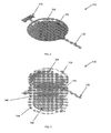
- FIG. 5 A plan view of an exemplary pump 100 having a cannula 120, suture holes 295, and a check-valve coupler 300 for affixing a check-valve, is shown in FIG. 5 .
- the coupler 300 facilitates affixation of the cannula 120 to a separate check-valve assembly by mechanical and/or adhesive means.
- the illustrated pump 100 includes six suture holes 295 positioned at an outer edge of the shell 160 and along the length of the cannula 120 to facilitate affixation of the pump 100 at a treatment site.
- the suture holes 295 may have an inner diameter, for example, of 400 ⁇ m and an outer diameter of 800 ⁇ m, although larger or smaller suture holes may be used. Additionally, a greater or lesser number of suture holes 295 may be used, and the suture holes 295 may be located at any appropriate location on the shell 160 and/or cannula 120 of the pump 100.
- the parylene layers used to form the diaphragm 150 and/or other pump layers have a 20 ⁇ m thickness.
- the outer dimensions of the drug chamber 130 may form a substantially elliptical shape having dimensions of 9mm x 6mm, while the outer dimensions of the corrugated diaphragm 150 may form an elliptical shape having dimensions of 7mm x 6mm.
- the delivery cannula 120 may be 6mm long and 400 ⁇ m wide, with an inner channel dimension of 20 ⁇ m x 100 ⁇ m.
- larger or smaller pumps and/or components thereof may be used, and the pump 100 may have any appropriate geometrical shape including, but not limited to, an ellipse, a circle, a square, or a rectangle.
- FIG. 6 A perspective view of an exemplary implantable pump 310 is shown in FIG. 6 , while an exploded perspective view of the pump 310 is shown in FIG. 7 .
- the pump 310 includes a top layer 320 including a domed portion 330 with a cannula 120 attached thereto.
- a middle deflection layer 340 forms the diaphragm 150 dividing the drug chamber from the electrolysis chamber.
- this diaphragm 150 may include corrugations 350 to facilitate expansion and contraction of the diaphragm 150 in response to electrolysis of gas from the electrolytic fluid in the electrolysis chamber.
- the diaphragm 150 may have a bellows type structure in addition to, or in place of, the corrugations 350.
- the layers forming the pump 310 may include, or consist essentially of, parylene.
- the pump 310 further includes a bottom layer 360 with electrolysis electrodes 380 coupled thereto or embedded therein.
- the electrolysis electrodes 380 are coupled to integrated control circuitry 370 for providing power to the electrolysis electrodes 380, and thereby controlling the pumping of fluid from the drug chamber.
- the circuitry 370 may be located in the same plane as the electrolysis electrodes 380 or may be positioned below the electrolysis electrodes 380.
- the three Parylene layers 320, 340, and 360 may be bonded together using thermal bonding, or through other appropriate bonding techniques including, but not limited to, chemical bonding, epoxy bonding, and/or pressure bonding.
- a drug chamber is formed between the top layer 320 and the middle deflection layer 340, while the electrolysis chamber is formed between the middle deflection layer 340 and the bottom layer 360.
- One or more openings may be left for filling electrolyte and drug separately into the electrolysis chamber and the drug chamber.
- the opening may then bonded and the chambers sealed, e.g., by thermal bonding.
- one or more refill ports that utilize a one-way valve can be incorporated to allow for filling/refilling, flushing, etc. of the drug and/or electrolysis chambers.
- a pump 100, 310 may, if desired, include multiple cannulas 120 arranged to extend from one or more locations on the pump 100,310 toward multiple treatment sites surrounding the pump 100, 310.
- each cannula has a separate check valve 220 , pressure sensor, chemical sensor, and/or flow sensor 205 associated therewith.
- a check valve 200 may be used to control the flow through multiple cannulas 120, and/or a single pressure sensor and/or flow sensor 205 may monitor conditions within multiple cannulas 120.
- the cannulas 120 may surround the dorsal nerve root of a recently fused spine, with the pump 100,310 impelling steroids for an extended period (e.g., six months) after surgery to reduce inflammation, improve healing time, and lower pain (and possibly the need for another surgery).
- the device can be superficially placed just below the fat pad, allowing a minimally invasive procedure to be performed to explant the device with limited risk and cost to the patient (compared to the cost/risk of removing a larger drug-delivery device or long catheter).
- no cannula is required, with the drug being pumped through one or more holes/perforations in one or more walls of the drug chamber 130 directly into the surrounding body.
- One embodiment of the invention includes a pump 100 including multiple drug chambers 130 each of which can be associated with separate electrolysis chambers 140 or be driven be a single electrolysis chamber 140. Separate cannulas 120 and/or refill ports 220 may be associated with each of the plurality of drug chambers 130.
- One embodiment of the invention may include a plurality of electrolysis chambers 140, with separate electrolysis electrodes 240 associated therewith. Refill ports 220 may be placed in fluid communication with one or more of the chambers 130, 140.
- the diaphragm 150 is controllably expanded toward a drug chamber 130 using other methods in addition to, or in place of, inducing gas electrolysis from a fluid held within an electrolysis chamber.
- Such methods may include, but are not limited to, mechanically driven means (e.g., threaded motors), electro-magnetically driven means, pneumatic means, or combinations thereof.
- one embodiment of the invention includes an implantable drug-delivery pump 100 having a drug chamber 130 and an electrolysis chamber 140 with a perforated shell 400 positioned above the drug chamber 130.
- the perforated shell 400 provides protection for the pump components while allowing a body fluid to flow through the perforated shell 400 to offset any vacuum pressure generated on the surface of the drug chamber 130 as the volume of drug within the drug chamber 130 is reduced through the pumping of the drug through the cannula 120 and into a treatment site.
- vacuum pressure is generally generated on the outer wall 110 of the drug chamber 130. This pressure resists fluid outflow from the drug chamber 130, thereby increasing the force that must be exerted by the expanding membrane 150 to expel fluid from the drug chamber 130.
- vacuum pressure may also be generated against the drug chamber 130 as the diaphragm 150 of the electrolysis chamber 140 returns to its original position.
- the protective shell 400 having one or more perforations 410 to permit ingress of surrounding body fluid into the space between the shell 400 and the outer wall 110 of the drug chamber 130, the vacuum pressure exerted on the drug chamber 130 is automatically balanced by the inflowing bodily fluid, thereby maintaining a consistent actuation time and conserving battery power.
- the protective shell 400 may be a substantially solid shell, while the perforations 410 may be of any size, shape, and/or number necessary to provide a sufficient flow rate from the surrounding bodily fluid into the cavity between the shell 400 and the drug chamber 130.
- the perforations 410 may cover the entire portion of the shell 400 covering the drug chamber 130, or only a portion thereof.
- the shell 400 may include, or consist essentially of, polypropylene.
- the shell 400 may include, or consist essentially of, any other appropriate material such as, but not limited to, a biocompatible plastic material, a metal (e.g., titanium, niobium, tantalum), or other material providing sufficient rigidity and mechanical strength to protect the pump 100 while exhibiting sufficient biocompatibility to be placed within a patient for an extended period.
- the shell 400, or a portion thereof has a thickness greater than 0.1 mm.
- the perforated shell 400 may be at least partially coated by a coating such as, but not limited to, a biocompatible material (e.g. parylene).
- the perforated shell 400 has three main functions: mechanical protection, balancing vacuum pressure in the drug chamber 130, and integration of the refill port 220.
- the hard shell 400 provides protection against mechanical damage during implantation, refilling, or at any time that the pump 100 is exposed to large pressures (which, if transmitted to the drug chamber 130, may cause unwanted delivery of the drug).
- the mechanical strength of the shell 400 can be designed and optimized by selecting different materials, shell thicknesses, 3-D profile, and geometry (e.g., shape, size, etc.) and distribution of the perforations 410.
- the perforations 410 may be large enough to create minimal resistance to fluid inflow and outflow, but small enough to provide adequate protection against mechanical damage.
- the perforations 410 have diameters smaller than the diameter of a refill needle, thereby preventing its entry.
- the perforations 410 are larger but covered, so that a uniformly solid exterior is presented to external objects that approach the pump 100.
- each perforation 410 may have an overlying cover, which is larger in diameter than the perforation 410 and supported thereover by pillars or other appropriate structures.
- the cover may be supported over a perforation 410 by a mesh or screen.
- the shell 400 comprises a meshed and/or woven structure.
- one embodiment of the invention includes an implantable drug-delivery system including a pump 450 driven by a passive osmosis-based mechanism.
- Implantable drug-delivery systems that utilize a passive mechanism for drug delivery can eliminate or limit the need for control electronics and power sources, thereby potentially reducing size, cost, complexity, safety, biocompatibility concerns, etc.
- Such pump-delivery systems can be placed in proximity to the surgical site after a surgical procedure, enabling targeted dispensing of a drug through one or more cannulas 120 in a localized region.
- active or passive osmotic pumps can be beneficial to ocular applications by lowering the size, cost, and power requirements over existing pumps, while still delivering active medication directly to the anterior or posterior chamber or subretinal area.
- some traditional drug-pump cannulas may be subject to biofouling, or the clogging of tissue and cells in the cannula, which prevents the outflow of drag particularly in devices where considerable time elapses between bolus injections.
- biofouling or the clogging of tissue and cells in the cannula, which prevents the outflow of drag particularly in devices where considerable time elapses between bolus injections.
- a drug pump only impels drug every 24 hours, it is almost always dormant, and therefore debris and cells can clog the system, making it less efficient or plugging the outflow.
- biological debris can be prevented from collecting due to the continuous operation of the device.
- the osmosis-driven pump 450 includes active electronics, powered by a battery or inductive telemetry, to control the opening and closing of an active check valve 200, thereby achieving active control of the pulsatile delivery of the osmotic device, while still keeping overall system power requirements below those of, for example, electrolysis-based pumps.
- the osmotic drug-delivery pump 450 includes a drug chamber/reservoir 130 containing one or more drugs or other therapeutic delivery agents.
- a cannula 120, or other tube or orifice is in fluid communication with the drug chamber 130 to facilitate accurate delivery of a drug held within the drug chamber 130 to a targeted treatment site within a patient.
- the pump 450 further includes an osmosis chamber 460 containing a solvent (e.g., water) and solute (e.g., NaCl).
- a membrane 150 e.g., a corrugated, elastic, and/or bellows membrane
- At least a portion of an outer wall of the osmosis chamber 460 includes a permeable or semi-permeable membrane 470 that, for example, permits passage of the solvent but is not (or is minimally) permeable to the solute contained in the osmosis chamber 460.
- the permeable membrane 470 is manufactured as part of the osmosis chamber 460. In an alternative embodiment, the permeable membrane 470 is manufactured separately and integrated with the chamber 460 in a separate step.
- placing the pump 450 in a solvent results in a net flux of the solvent across the permeable or semi-permeable membrane 470.
- the magnitude of the flux is determined in part by the degree of permeability of the membrane 470 to the solvent.
- This net flux results in a flow of solvent (e.g. water) into the osmosis chamber 460 from the surrounding body, which in turn increases the pressure in the osmosis chamber 460.
- solvent e.g. water
- the increase in pressure deflects the membrane 150 into the drug chamber 130, thereby decreasing its volume and forcing the drug held within the drug chamber 130 through the cannula 120 and out to the targeted treatment site.
- the pump 450 includes other (e.g., biocompatible) components, such as a protective shell, housing, enclosure, or covering, that provide protection to, and/or help maintain the structural integrity of, the pump 450.
- Other components that may be incorporated into the pump 450 include refill ports for one or both of the chambers 130, 460, one or more flow and/or pressure sensors 205, and/or one or more check-valves 200 to prevent back-flow.
- the pump 450 may also incorporate active electronics, e.g., to monitor flow rate of the drug, record dosing schedules, and/or ensure proper function.
- the osmotic drug-delivery pump 450 may be monolithically microfabricated utilizing multiple polymer layers that are later bonded together using any of a number of common packaging techniques (e.g., thermal bonding of the layers).
- the pump 450 utilizes parylene or other biocompatible material to achieve an active device with full biocompatibility.
- the drug chamber 130, cannula 120, and check valve 200 may all be formed from one or more parylene sheets.
- the pump 450 is flexible and easy to fit into a protective shell with optimized implantation 3D geometry.
- another embodiment of the invention includes an implantable drug-delivery system including a pump 500 having an osmosis chamber 510 to prevent, as earlier described, the accumulation of vacuum pressure on the drug chamber 130.
- This osmosis chamber 510 may be utilized to automatically balance a vacuum pressure on the drug chamber 130 after each electrolysis dosing, thereby maintaining a consistent actuation time and conserving battery power.
- the pump 500 includes an electrolysis chamber 140 and electrolysis electrodes 240, as described hereinabove.
- the osmosis chamber 510 overlies the drug chamber 130 and these two chambers are separated by a fluid barrier such as, but not limited to, a corrugated diaphragm 520.
- the top layer 530 of the osmosis chamber 510 may include a thin-film, semi-permeable osmotic membrane 540 that may, in one embodiment, be integrated with (e.g., uniformly attached to) a perforated protective hard shell 550.
- the perforations expose the osmotic membrane 540 to surrounding fluid.
- no permeable hard shell 550 is required, with the semi-permeable osmotic membrane 540 itself being structured with sufficient strength and rigidity to provide a protective covering for the pump 500.
- one or more of the chambers 130, 140, 510 include a refill port in fluid communication therewith.
- a refill port 560 may be coupled to the osmosis chamber 510, and may, for example, be mounted through the hard shell 550.
- the osmosis chamber 510 may be filed with a fluid such as, but not limited to, a solute and solvent (e.g., NaCl in water).
- Fluids that may be used in the osmosis chamber 510 also include a saline solution, a solution including magnesium sulfate, a solution including sodium sulfate, pure water, or any non-toxic solution.
- the electrolyte when current is supplied to the electrolysis electrodes 240, the electrolyte generates electrolysis gas, expanding the diaphragm 150, and forcing liquid out of the drug chamber 130 through the cannula 120.
- the current to the electrolysis electrodes 240 is stopped, and the gas dissipates back into its liquid state within the electrolysis chamber 140, the corrugated diaphragm 150 above the electrolysis chamber 140 recovers its space-efficient corrugations. Because of the reduced drug volume after dosing and the closed check valve 200 in the cannula 120, vacuum pressure is generated against the drug chamber 130 as the diaphragm 150 above the electrolysis chamber 140 returns to its original position.
- fluid e.g., water
- the osmosis chamber 510 may initially be charged with a liquid that is hypertonic relative to the external bodily fluid.
- water tends to flow through the osmotic membrane 540 and into the osmotic chamber 510.
- the incoming water equalizes the pressure on both sides of the upper drug chamber membrane 520, with the equalized pressure in the drug chamber 130 helping to reduce the deflection of the diaphragm 150 necessary to generate a check valve cracking pressure, therefore saving pump operation power.
- osmotic pressure when the pump 100 is in rest status, osmotic pressure will reach balance with the drug chamber 130 pressure, which is lower than a check valve cracking pressure, until the next dosing which creates lower pressure in the drug chamber 130, after which a new balance status will be reached.
- concentration of the osmosis chamber is selected such that the balance pressure after the final dosage won't exceed a check valve cracking pressure.
- the osmotic pressure driving the flow depends on the solute concentration in the osmotic chamber 510 (relative to the surrounding fluid) and the degree of permeability of the membrane 540.
- the solute concentration in the osmotic chamber 510 is low enough to keep the osmotic pressure well below the cracking pressure of the cannula check valve 200 (so that fluid is never improperly expelled from the drug chamber 130).
- the concentration of osmotic solute decreases. Accordingly, while the initial solute concentration cannot be so high as to cause fluid to be driven out of the drug chamber 130, it should be sufficiently high that, despite its gradual dilution, it remains adequate to draw liquid through the osmotic membrane 540 until the supply of drug has been fully dispensed.
- the drug chamber 130 may be refilled through the refill port 220, and the osmosis chamber 510 is purged and refilled with the hypertonic liquid through the osmosis chamber refill port 560.
- filling the drug chamber 130 with the osmosis-chamber refill port 560 open may accomplish the necessary purging of the osmosis chamber 510.
- the invention includes an outer package to provide a protective enclosure for at least a portion of the pump.
- Exemplary packages 600 are shown in FIGS. 13 through 19 .
- the package 600 may be manufactured, at least in part, from materials such as, but not limited to, a metal (e.g. titanium, tantalum, or niobium), an alloy (e.g. nitinol (TiNi)) polypropylene, polyimide, polyetheretherketone (PEEK), glass, ceramic, and/or epoxy.
- the shell may be fabricated using techniques such as, but not limited to, computer numerical control (CNC) milling, stamping, extrusion, and/or injection molding.
- the package 600 may be at least partially coated by a coating such as, but not limited to, a biocompatible material (e.g. parylene).
- a first exemplary package 600 for an implantable drug-delivery pump is shown in FIGS. 13 andl4.
- the package 600 includes a hermetic enclosure 635 and a dome-shaped protective shell 160 that has a recessed shape (including a concave lower portion 610) that may be obtained through, for example, hydraulic stamping or CNC-machining.
- the dimensions and height of the device depend on the function, location, size of electronics and power source, etc., and can be tailored to a specific application and/or patient.
- the package 600 is designed for intra-ocular deployment and has dimensions of approximately 14mm (L) x 10mm (W) x 4mm (H). In alternative embodiments, smaller, larger, or differently proportioned shells may be utilized.
- the hermetic enclosure 635 may provide a housing containing elements including, but not limited to, the control electronics, a power source, and/or a communication means, as described herein. Elements such as the electronics and power source may be disposed within the hermetic enclosure 635 in a stacked configuration to provide a smaller footprint, or side-by-side to provide a shallower form factor.
- the hermetic enclosure 635 includes an endplate 620 enclosing the recessed area, which can be attached thereto in a manner suited to the material, e.g., welding or bonding, to provide a hermetic seal.
- the hermetic enclosure 635 (or another surface of the enclosure) may include feed-through elements to allow electrical connections to span the internal electronics and external elements accessible outside the hermetically sealed pump. These external elements may include, for example, a coil for a wireless charging/telemetry link, the electrolysis electrodes and sensor connections in the pump, and/or the electrodes in a stimulation device, etc. Removal of the endplate 620 facilitates access to these "external" components.
- the coil may be molded to the package 600.
- the hermetic enclosure 635 may be fabricated from injection-molded plastic or potted epoxy, such that all of the electronics and power source are hermetically encased within the hermetic enclosure 635 as it is manufactured so that no separate endplate is necessary.
- the hermetic enclosure 635 includes an upper an lower surface that are hermetically sealed together after placing the circuitry 170 and/or other components therein.
- One or more cannulas 120 may extend through the shell and be in fluid communication with one or more drug chambers housed within the package 600.
- the cannula(s) 120 may be of any appropriate length, diameter, and curvature as required to deliver drug to a particular treatment site.
- a silicone or similar tube is added around the cannula 120 (and may be backfilled with a silicone-type adhesive) for added strength/durability and/or to create rounded edges to minimize irritation to surrounding tissue and at the incision/point of entry (e.g., into the vitreous cavity).
- the shape and size of the package 600 are dictated by its function and can be designed to suit any particular geometry.
- the package 600 houses an intra-ocular drug pump and is shaped to match the curvature of an eyeball upon which it is to be surgically mounted. This may be achieved by milling, injection molding (in the case of polymers such as polypropylene), or by doming the structure, e.g., with a hydraulic press and tooling (in the case of a metal such as titanium).
- the endplate 620 can be shaped to match the curvature of the package 600 so that the interior volume of the package 600 remains constant.
- the thickness and/or width of the package 600 are tapered, providing a teardrop shape.
- the profile and edges of the package 600 may be rounded to minimize the risk of damage to tissue structures in direct contact therewith, as well as to maximize comfort for the patient and ease implantation for the surgeon.
- the rounded corners and edges (alone or in conjunction with the teardrop shape previously mentioned) on an intraocular drug pump can ease surgical implantation when inserted into an incision in the conjunctiva or sclera of the eye, or the parenchyma of the brain, and also reduce irritation or inflammation at the site of implantation.
- the device is a small drug pump with a protective shell 160 that covers a drug reservoir and an electrolysis chamber.
- the shell 160 may be made from a durable material such as, but not limited to, titanium, nitinol, tantalum, niobium, polypropylene, polyimide, glass, ceramic, PEEK, and/or epoxy, as described above, and may be added to protect components of the pump, such as, but not limited to one or more drug chambers.
- the shell 160 may have perforations or holes to permit the influx of a fluid for pressure equalization of the drug chamber of the pump.
- a shell 160 (with a drug chamber 130 and electrolysis chamber 140 enclosed thereunder) may be coupled to, and sit atop, the hermetic enclosure 635, enclosing the electronics and battery.
- the drug chamber 130, electrolysis chamber, and/or protective shell 160 may be attached in a manner suitable to the material of the hermetic enclosure 635, such as, but not limited to, adhesive means.
- the shell 160, and pump elements e.g. drug chamber 130 and electrolysis chamber, may be located adjacent to the hermetic enclosure 635 as opposed to atop the hermetic enclosure 635, thereby reducing the overall height.
- FIGS. 20 to 23 An example package 600 having a shell 160 (with drug chamber 130 and electrolysis chamber 140 enclosed thereunder) adjacent to the electronics and power source sub-assemblies 660 is shown in FIGS. 20 to 23 .
- Affixation using an adhesive has the advantage, for example, of allowing a two-step sterilization process. For example, it may not be possible to expose the package 600 to gamma radiation (e.g., because it encloses vulnerable electronics or is itself subject to damage), but it can be sterilized with, e.g., ethylene oxide gas.
- the shell 160 and pump elements may be impervious to ethylene oxide gas but amenable to sterilization with gamma radiation. In such implementations, it is possible to sterilize the shell 160 and pump elements with gamma radiation, attach it to the hermetic enclosure 635 in a sterile environment, and then sterilize the whole package 600 using ethylene oxide.
- the cannula 120 is fed through the shell 160 and the interface between the cannula 120 and the shell 160 sealed with a silicone or other suitable material, e.g., epoxy.
- a silicone or other suitable material e.g., epoxy.
- This configuration may be beneficial in providing protection to the pump structure without requiring an additional shell above the dome of the pump to add structural support.
- the shell 160 may be encased with the other sub-assemblies in an injection-molded or potted epoxy enclosure.
- the cannula 120 may be contained within a tubing sleeve made, for example, from silicone or a similar material, to provide additional structural integrity and protection to the cannula 120. This sleeve may be backfilled with a silicone or similar adhesive.
- the rigid enclosure can also serve as a safety "stop" to prevent the needle from going too far and damaging the device or injuring the patient and/or to assist in guiding the needle into the refill port.
- the outer shell may contain a refill port 690 fabricated from silicone or a similar material.
- the refill port 690 may be located at any appropriate position on the package 600 and provide easy access by a surgeon after implantation, using the rigid shell to prevent over-insertion of the needle or alternately to guide the needle (e.g., a channel in the rigid shell).
- the shell may include eyelets 670, or other structures extending from the hermetic enclosure 635, for securing the device to a treatment site using sutures.
- the eyelets 670 are rounded to prevent irritation or damage to the surrounding tissue, and are located at the top of the device to aid in implanting and securing the device against the eye. This can also be helpful in the brain, spine and knee.
- one or more suture eyelets 670 may be positioned at any location around an exterior of a package 600 to allow the device to be secured in place easily by the surgeon.
- the package 600 may include a portion including one or more perforations to enables a fluid flow to pass through the shell to an interior portion thereof to provide pressure equalization, solvent permeation in an osmotic pump, etc.
- the shell is manufactured with one or more coils 680 integrated therein to provide wireless telemetry and/or recharging. This may be achieved, for example, by injection molding of the package 600 with the coil 680 in place.
- FIG. 24 depicts a schematic sectional view of another pump 100 embodiment that has a package 600 including a hermetically enclosure 635 containing the electronics and battery.
- a ceramic header 675 with electrical feed-throughs 685 is brazed to top of the biocompatible metal (e.g. titanium, niobium, tantalum or nitinol) case to form the hermetic enclosure.
- the metal or ceramic alone can form the entire hermetic enclosure 635 with insulated feed-throughs 685 brazed on.
- the feed-throughs 685 are for the control of the electrolysis electrode, the sensors and/or for the connection to the telemetry coil/antenna (not shown) that is molded on the shell 160.
- the ceramic electrolysis chip 665 containing the electrolysis electrodes is located on top of the hermetic enclosure 635.
- a spacer 670 with a set thickness may be placed around and beneath the edge of the diaphragm 150 to create volume.
- a filling tube can be coupled to the fill hole and sealed after filling.
- the spacer 670 may be formed from a material such as, but not limited to, a metal (e.g. Titanium), ceramic, plastic, and/or other biocompatible material.
- the top drug reservoir wall 160 may have two fluid ports. One port 655 is to couple with a cannula for drug delivery and the other 220 for connecting with a refill port through a tube (not shown).
- Power for the device can be provided by several different technologies including both standard chemical-based batteries and/or capacitors that store a charge in an electric field. It is also possible to provide power via a wireless inductive link instead of on-board power-storage capabilities. (Alternatively, as described below, the inductive link can be used to charge/recharge an on-board battery or capacitor.)
- the power source may include a coil in an inductive link, which may include a ferrite core.
- the power source is provided by a primary (i.e., non-rechargeable) or secondary (i.e., rechargeable) lithium-based battery (e.g., a lithium-ion, lithium-polymer, or lithium phosphorus oxynitride (LiPON) battery).
- a primary (i.e., non-rechargeable) or secondary (i.e., rechargeable) lithium-based battery e.g., a lithium-ion, lithium-polymer, or lithium phosphorus oxynitride (LiPON) battery.
- LiPON lithium-ion, lithium-polymer, or lithium phosphorus oxynitride
- the device utilizes a LiPON thin-film solid-state battery, which offers high charge density in extremely thin and small form factors.
- the solid-state structure of LiPON is inherently safer than many other lithium and liquid/chemical based batteries that can suffer outgassing, leakage, and even explosion.
- Providing an extremely thin power source allows
- an a rigid outer enclosure or shell (formed, for example, from a biocompatible material such as, but not limited to, titanium, tantalum, nitinol, or niobium) may encase components of the pump to provide protection for the components.
- the protective shell may house both pump components and electronic components such as, but not limited to the battery, the device electronics and the battery technology may be enclosed in a single, hermetically-sealed shell without the need to provide separate shells for different components.
- the battery and electronics power and control a drug pump made from parylene.
- a LiPON battery is deposited on a layer or sheet of parylene that may or may not be integrated with the parylene pump structure.
- An energy-storage source suitable for use in connection with a drug pump may include a battery and/or capacitor integrated into the implantable device.
- the battery utilizes a LiPON thin film as a lithium electrolyte.
- LiPON may be advantageous, for example, by providing improved size/geometry, safety, and/or charge capacity than certain other technologies.
- LiPON technology for example, it is possible to achieve a high charge density in a small form factor, which may be critical for implantable devices.
- LiPON batteries can also be made extremely thin, allowing for a flexible design that can fit the curvature of an implantable device designed to lie flat against the eye or brain, for example. Because they are inherently thin, several individual cells may be stacked to increase voltage (by connecting the cells in series) or to increase capacity (by connecting them in parallel) while still maintaining a thin profile.
- LiPON batteries may be manufactured by depositing thin layers of different materials on a substrate to form the anode, cathode, and electrolyte. After deposition, the layers are typically sealed (e.g., by means of a laminate) in order to prevent chemical reactions caused by interaction with the surrounding air that would significantly shorten the life of the battery. The battery's lifespan can further be extended by installing the battery in a hermetically sealed enclosure containing an inert environment (e.g., argon).
- the substrate comprises, or consists essentially of, a polyimide sheet (e.g., KAPTON).
- the advantage of depositing the battery onto a polyimide sheet is that this substrate can additionally serve as the circuit board for the electronics, providing electrical interconnects between different components that are mounted on the polyimide substrate through standard electronics-manufacturing techniques (solder, conductive epoxy, etc.). Therefore, the battery and electronics are all borne by a single monolithic substrate.
- the underside of a polyimide sheet can support multiple battery layers while the electronic components and integrated circuits can be mounted on the topside.
- the battery layers are deposited on a thin sheet of parylene, from which the mechanical pumping mechanism may be formed.
- This approach also has the benefit of providing a single, integrated structure for the battery and another component of the implant (in this case, the pumping mechanism).
- the battery layers can be deposited on a sheet of parylene that is not used for any other function. Parylene can also be deposited over the exposed battery structures (e.g., anode, electrolyte, cathode) in sufficient thicknesses (e.g., 3 ⁇ m or greater) to ensure pinhole-free seals protecting the battery structures from exposure to surrounding air.
- a backup power source such as a second battery
- the second battery can serve as a total replacement for the first (so that it continues to power all functions) or it can exist merely to provide enough power to properly shut the device down, alert the user, or perform some other critical function in the event of a failure of the main power source.
- LiPON batteries for example, are well suited to this task, at least because of their stackable nature.
- the battery is actually two (or more) battery elements stacked on top of each other.
- the capacity of the backup battery can match that of the main battery, or it can store only a fraction of the energy stored in the main battery (e.g., 20% of the main battery's capacity). Circuitry incorporated in the electronics sub-assembly of the implantable device, or even within the battery sub-assembly itself, can detect failure (such as a short circuit or depleted power) and switch to the backup battery if necessary.
- One embodiment of the invention may include a power supply including a rechargeable battery, such as, but not limited to, a rechargeable LiPON battery.
- a rechargeable battery such as, but not limited to, a rechargeable LiPON battery.
- This may be highly desirable in an implanted device, as it obviates or at least defers the need for additional surgical procedures for changing batteries, etc.
- recharging is accomplished through utilization of an RF-coupled wireless power link and, for example, a near-field (e.g., inductively coupled) link, typically employing coils in the transmitter and receiver, or a far-field link, which may employ antennas in the receiver and coil.
- a near-field link typically employing coils in the transmitter and receiver
- a far-field link typically employ antennas in the receiver and coil.
- the frequency of operation can be chosen to suit the application; higher frequencies (e.g., 10 MHz) typically facilitate use of smaller electronic components, as well as enabling greater tissue penetration and higher efficiencies in power coupling, while lower frequencies (e.g., 400 kHz) typically offer lower power consumption and less potential tissue heating due to absorption.
- higher frequencies e.g., 10 MHz
- lower frequencies e.g., 400 kHz
- the substrate on which the battery is deposited also includes recharging circuitry such as, but not limited to, a coil and a capacitor connected to form a resonant circuit for inductive coupling, a rectification stage that converts the resulting alternating current (AC) to direct current (DC) and filters the resulting DC (e.g., through a lowpass filter stage) and a voltage-regulation stage that maintains the proper charging voltage regardless of external influences (movement of the coil, etc.) during the charging process.
- recharging circuitry such as, but not limited to, a coil and a capacitor connected to form a resonant circuit for inductive coupling, a rectification stage that converts the resulting alternating current (AC) to direct current (DC) and filters the resulting DC (e.g., through a lowpass filter stage) and a voltage-regulation stage that maintains the proper charging voltage regardless of external influences (movement of the coil, etc.) during the charging process.
- AC alternating current
- DC direct current
- recharging capability is accomplished using a photovoltaic cell on the same substrate as the LiPON battery.
- a photovoltaic cell on the same substrate as the LiPON battery.
- energy can be coupled to the device via the photovoltaic cell and a light source, e.g., a laser focused on the location of the implant.
- Suitable electronics may provide control and monitoring capabilities as well as any additional required functions for the device.
- the electronics control the pumping mechanism and measure the amount of drug administered.
- the complexity of the electronics depends on the required functionality, but may include highly complex and integrated functionality that can be packaged in small forms.
- the electronics includes off-the-shelf components such as, but not limited to, microcontrollers, op-amps, transistors, resistors, and/or capacitors enclosed in small packages. These components may be mounted on a printed circuit board that provides electrical interconnectivity.
- this printed circuit board is of the flex circuit variety (on a polyimide, e.g., KAPTON substrate) to minimize thickness and also provide flexibility so the electronics can match the curvature of the shell (which is itself designed to match the curvature of the eye, knee or brain).
- the components are packaged together in a system-on-chip (SoC) configuration, e.g., using chip-scale packaging or wafer/die-level and wirebond assembly.
- SoC system-on-chip
- the electronics functions may be custom-designed in an application-specific integrated circuit (ASIC).
- ASIC application-specific integrated circuit
- the electronics may be coated with a thin conformal coating (such as, but not limited to, epoxy or parylene) to prevent the possibility of a short circuit in the case of a conductive outer shell.
- a thin conformal coating such as, but not limited to, epoxy or parylene
- the electronics may also be potted in epoxy either with the shell, or the epoxy potting may serve as the shell itself.
- the electronics may be housed (e.g., in die or wafer form) in a parylene structure forming a portion of the pump system.
- the electronics may be wirebonded together, or connective traces may be integrated into the parylene.
- implantable pumps may include means of communicating with, and/or charging, the pump after implantation into a body. This may be advantageous, for example, where hardwired connections to a supply power and/or data communication functionality is impractical for an implanted device.
- embodiments of the present invention may utilize a wireless telemetry configuration, whereby power and data are transferred to and from the implant using electromagnetic radiation through means including, but not limited to, an RF link.
- the microelectronic implantable device may be coupled to an external device (a "reader/charger"). This external device may provide functions such as, but not limited to, a power supply, battery recharging, and/or forward and reverse telemetry.
- the external device can be used to provide power when in proximity to the implanted device, while for devices that incorporate an internal battery or other energy-storage device, the external device can be used to recharge the energy-storage device.
- the external device can also be used to transmit data to the implanted device and/or receive data sent by the implanted device. This data may include, but is not limited to, pump performance data, drug storage information, and/or medical readings. These functions may be integrated into a single external device, or may be divided among multiple devices. For example, one device may provide power and recharging capabilities while a different device may provide data telemetry functionality.
- the reader/charger (which may be a single device or multiple devices) is controlled by a microcontroller, microprocessor, FPGA, or other digital logic device as well as ancillary circuitry (e.g., random access memory, power regulation, etc.) to enable program storage and otherwise allow the processor to perform its function, and a power source such as rechargeable batteries or a transformer and regulator to facilitate connection to line voltage (110VAC/220VAC).
- the reader/charger may also incorporate non-volatile memory such as flash memory to store data of various types.
- the reader/charger may have USB or other interface capabilities to allow for data download, firmware updates, etc.
- the reader/charger may also incorporate a user interface, with a display (e.g., an LCD) that shows information, and buttons or a keypad enabling the user or clinician to interact with the reader/charger (and, thereby, the implanted device).
- the reader/charger includes a coil or antenna and driver circuitry including a power-amplification stage (e.g., class-C or class-E) specifically designed to couple to resonant circuitry (i.e., a coil and capacitor tuned to the resonant frequency) in the implantable device.
- the coil/antenna may be located within the same enclosure that houses the other components, or it may be external to the enclosure, for example, to facilitate charging and data transfer.
- the implantable device is an intraocular drug pump configured for surgical implantation below the conjunctiva on the eye or brain.
- the coil/antenna may be separate from the rest of the reader/charger and installed in a pair of eyeglasses, an eye patch for the eye, a headband for the brain, a kneebrace for the knee, or even a hat, and connected to the main reader/charger circuitry by a cable (or, in some cases, wirelessly).
- the coil is strategically located in a wearable appliance such that, with the appliance properly and naturally positioned on a user, optimal alignment between the implant coil and the reader/charger coil is enforced. This maximizes energy transfer and therefore minimizes recharge time.
- the frame when worn, will have a consistent alignment with the anatomy that does not vary substantially across wearers.
- This configuration enables the patient to wear the eyeglasses comfortably during the recharging cycle (which, depending on multiple factors, may take tens of minutes to a few hours).
- the bulk of the reader/charger can be located elsewhere, such as, but not limited to, in a unit that may be clipped to a patient's belt.
- the implantable device can communicate with a reader/charger including an audiovisual component, such as, but not limited to, a pair of "video glasses” or virtual-reality goggles.
- the eyeglasses may, if desired, have integrated LCD displays similar to virtual-reality goggles or the "video glasses” currently being sold to interface to audiovisual devices such as iPods. These glasses are capable of displaying video images.
- the patient can comfortably watch a movie or television show, for example, or an informative or educational video relevant to his or her treatment.
- the display can also be designed to display information regarding the charge/data telemetry cycle, such as time elapsed/remaining, percent charged, etc.
- the displays may be offset relative to the patient's line of sight so that the patient is forced to view the display at an angle, for example by turning his or her eyes toward the left or the right. This can be useful in achieving optimal coupling to an implant on one of the patient's eyes (e.g., so that the coupling occurs through air, which causes lower attenuation of the signal power than coupling through the flesh and bone near the temple).
- implantable pump systems in accordance with the invention may include a power and/or data telemetry system.
- a power telemetry system can convert received AC signals transmitted by the external device coil into a DC voltage, which can power the pump and/or recharge the pump's internal power supply.
- Power transmission is unidirectional and may be accomplished by wirelessly coupling power from an external coil to an internal coil integrated with the pump device packaging.
- the internal coil includes or consists essentially of a single or multiple strands (e.g., Litz) of wire with polymer insulation thermally formed by heat treatment into a specific shape.
- the coil can be shaped to conform to an anatomical surface, e.g., the eye, to which the pump is attached.
- the coil is fabricated through the deposition and etching of a conductive film (e.g., of gold or silver).
- the coil is fabricated through a lithographic process. More generally, the coil may be fabricated according to any approach convenient to the overall manufacturing process; numerous alternatives (e.g., using Litz wire) are well-known in the art.
- an implantable gold coil having a diameter of 1 cm, can achieve >100 mW coupling power using a portable, wearable, external coil.
- a data telemetry link may use the same set of coils as the power telemetry link, or may use a separate coil.
- the implanted coil can serve as both the transmit and the receive coil.
- the data telemetry functionality can be used, for example, to program device parameters before or after implantation, verify proper programming and functionality, and download status alerts, dosing schedules, and other relevant information stored by the pump (e.g., in non-volatile memory).
- antennas and/or coils may be located inside or integrated within a shell material for a pump system (in the case of non-attenuating materials such as polypropylene) or on the outside (in the case of metals and other shielding materials).
- a telemetry/recharging coil may be integrated into a parylene structure forming a portion of the pump system.
- an implantable pump in accordance with the invention can also incorporate a simple and inexpensive unidirectional, optical data-telemetry system (typically requiring fewer components, and less cost and space, than a radio frequency or inductive telemetry link) utilizing, for example, a photodiode or phototransistor.
- an external device transmits light signals (for example via a laser or LED) that have been modulated with data; these signals are detected by the photodiode or phototransistor and interpreted by the pump-borne microcontroller or other control circuitry.
- the phototransistor and device electronics are located in an enclosure made from a material such as, but not limited to, polypropylene, that is transparent to the wavelength of the optical signals.
- the electronics and phototransistor are located in an opaque (e.g., titanium) enclosure containing a transparent (e.g., sapphire) window hermetically sealed (e.g., through a brazing or welding process).
- a transparent (e.g., sapphire) window hermetically sealed (e.g., through a brazing or welding process).
- sapphire window is to allow an LED light source, attached to and controlled by the electronics, inside the enclosure to signal the patient or another use of some type of message, such as an error light or low battery signal.
- Other indicators in addition to light include vibration, audible signals, or shock (such as transcutaneous neural stimulation).
- the optical telemetry is used to program pump settings (e.g., the current date and time, the desired flow rate, dosing schedule, etc.) immediately prior to implantation, without removing the device from its package (assuming the packaging material is penetrable by the wavelength of the particular light source).
- program pump settings e.g., the current date and time, the desired flow rate, dosing schedule, etc.
- the optical communication can be made bidirectional (thereby enabling the pump to transmit data as well) by adding a light-emitting diode (LED) to the pump circuitry.
- the LED can emit in the infrared or visible spectrum; for example, an indicator LED may be used for communication functions in addition to display.
- the bidirectional communication enables the pump to communicate with an external device, for example, to verify proper programming and settings before implantation.
- the LED may also be used as a photodiode either in photovoltaic mode or photocurrent mode, thereby saving cost and space by using a single component for both transmit and receive functions.
- control circuitry described herein may be used to detect electrical failures and, for example, switch to a backup battery, if necessary. More generally, the control circuit can be configured to detect any number of failure conditions and to take appropriate ameliorative action. For example, if a malfunction or fault state in the pumping mechanism is detected, the control circuitry may trigger an alert to the patient.
- the alert may take the form of an optical signal (from the LED described above, for example, which will be immediately visible in ocular deployments); vibration; transcutaneous electric neurostimulation (e.g. giving an electrical shock to the eye); or an audible signal.
- the alert may include one or more lights blinking from an LED on the surface of the pump to alert patient in mirror, or LED on an undersurface of a pump to alert the patient's eye through endoillumination.
- Alerts may be used to notify a patient of events such as, but not limited to, malfunction, low battery, low drug.
- the control circuitry may communicate details of the failure condition to the wireless reader when it is brought into proximity.
- Other alerts such as audible signals (e.g. beeping), noises, vibration, and electrical shock may also be used in addition to. Or instead of, an optical signal, as described above.
- an implantable drug-delivery pump may be manufactured using techniques including, but not limited to, bonding (e.g., thermal bonding), lithographic etching, and/or other suitable manufacturing techniques. Exemplary techniques for manufacturing various components of the pumps described herein are described below. It should be noted that the methods of manufacture described below are presented as representative examples, and any of the pumps and/or components thereof may be formed using any of the manufacturing methods described, as appropriate, or other suitable methods.
- FIGS. 25A-25F An exemplary method of manufacturing a drug chamber 130 with integrated cannula 120 for a pump 100 using lithographic fabrication processes is shown in FIGS. 25A-25F .
- a pump 100 having a drug chamber 130, electrolysis chamber 140, and integrated cannula 120 is formed from a plurality of patterned parylene layers.
- the fabrication process flow includes the steps of:
- the drug chamber 130 and cannula 120 are both appropriate form implantation within a body for safe extended use.
- multiple parylene layers can be processed to make other layers of a pump 100, such as, but not limited to a bottom layer of an electrolysis chamber 140.
- a pump 100 may be manufactured by separately forming the discrete layers of the pump 100 (e.g., an upper surface of a drug chamber 130 with integrated cannula 120, a diaphragm 150 dividing the drug chamber 130 and electrolysis chamber 140, and/or a bottom later of an electrolysis chamber 140), and thereafter bonding these layers together through, e.g., thermal and/or chemical bonding.
- the discrete layers of the pump 100 e.g., an upper surface of a drug chamber 130 with integrated cannula 120, a diaphragm 150 dividing the drug chamber 130 and electrolysis chamber 140, and/or a bottom later of an electrolysis chamber 140
- a top layer 700 of a drug chamber 130 including an integrated cannula 120 may be manufactured through methods including, but not limited to, molding and/or lithographic etching techniques. An exemplary method of forming a top layer 700 is described below.
- the top layer 700 may have dimensions such as, but not limited to, 9mm in diameter and 4mm in height, with a 9mm cannula 120 with a micro-channel (9mm in length, 150 ⁇ m in width and 20 ⁇ m in height).
- the top layer 700 is formed by coating a layer of material, such as, but not limited to, parylene, of a predetermined thickness onto a mold (e.g., a metal mold formed, for example, from aluminum). After the parylene coating has set, the resulting parylene dome structure may simply be peeled off of the mechanical mold. A cannula 120 may thereafter be inserted into, and/or bonded onto, the parylene structure through a preformed hole.
- the preformed hole in the top layer 700 may be formed after molding the top layer, for example by piercing the top layer 700 with a sharp object, or may be formed during the molding process itself (with the hole feature created by the mold.
- a top layer 700 is fabricated using a CNC machined mold.
- a release layer is applied to the mold using spray, dip, and/or other coating methods. Parylene is then deposited on the mold. Afterwards, the molds are soaked in a solution that will dissolve the release layer.
- the top layer 700 is formed by placing a sheet of material (e.g., parylene) between opposing mating surface of a preformed mold.
- the opposing mating surfaces may be formed from a metal (e.g., aluminum), a plastic, rubber, or another material exhibiting the required strength, thermal properties, and chemical stability.
- the parylene dome structure for the top layer 700 is then made by pressing a flat parylene sheet between the mold portions, and annealed in a vacuum oven (e.g., at a temperature such as, but not limited to, under 180°C to 200°C), after which the mold may be separated and the completed part removed.
- a parylene cannula 120 incorporating a micro-channel may be fabricated by a lithography process using two parylene layers, as shown in FIGS. 27A-27F .
- the steps include:
- a parylene dome structure 730 may be bonded to the cannula 120, as shown in FIG. 28 .
- a through-hole is created, e.g., with a hot metal probe, at the edge of the dome 730 and the parylene cannula 120 is bonded to the parylene dome 730, e.g., using a biocompatible epoxy, while ensuring the through holes in the dome structure and the parylene cannula are properly aligned.
- a cannula 120 and top layer of a drug chamber 130 may be formed using a lithography process.
- another parylene layer e.g., 20 ⁇ m in thickness
- this method integrates the parylene cannula 120 and the dome structure using lithography. As a result, the alignment and epoxy bonding work is not needed.
- the lithography fabrication method may increase the reliability of the device. The steps include:
- One manufacturing method includes a lithography process to integrate a check valve 200 and flow sensor 205 inside a parylene micro-channel cannula 120.
- the check valve 200 is used to prevent drug leakage from the drug chamber when the pump 100 is at rest and during the refilling.
- the check valve 200 also prevents back-flow due to intraocular pressure after implantation, such as during a patient's sneeze or pressurization on an airplane.
- An exemplary check valve 200 is a bandpass check valve.
- the check valve's cracking pressure prevents leakage when the pump is at rest (and during the refill process), but the valve will open to allow forward flow when the electrolysis pumping action is working normally to generate a pressure exceeding the cracking pressure.
- the check valve 200 will shut down the forward the flow.
- the check valve 200 will prevent backward flow resulting from the intraocular pressure.
- a bandpass check valve may be manufactured by combining one normally closed and one normally open check valve, as shown in FIG. 30 .
- a thermal, time-of-fight, capacitive or other type of flow sensor 205 may be used in the micro-channel cannula 120.
- the flow sensor 205 may be on upstream or downstream of the check valve to monitor the drug pumping rate and/or the total volume.
- the flow sensor includes two parts: a heater on the upstream side to generate a heat pulse in the flow, and a thermal sensor or other type of sensor to sense and pick up the pulse. By monitoring the exact time between application of the heat pulse and its detection by the sensor the flow rate may be precisely established and, using a microcontroller, a total volume of pumped drug may be calculated.
- FIGS. 31A-31J An exemplary process for manufacturing a micro-channel cannula 120 with integrated check valve 200 and flow sensor 205 is shown in FIGS. 31A-31J .
- the manufacturing steps include:
- a diaphragm 150 with corrugations may be formed by coating a layer of material such as, but not limited to, parylene, over a mold.
- diaphragm 150 with corrugations may be formed by placing a parylene sheet between two complementary mold portions, and annealing the mold and sheet at a set temperature to form the required structure.
- a diaphragm 150 with corrugations may be formed by a lithographic process, as shown in FIGS. 33A-33E .
- the manufacturing steps include:
- a diaphragm 150 with bellows may be formed by coating a layer of material such as, but not limited to, parylene, over a mold.
- diaphragm 150 with bellows may be formed by placing a parylene sheet between two complementary mold portions, and annealing the mold and sheet at a set temperature to form the required structure.
- a diaphragm 150 with bellows may be formed by a lithographic process, as shown in FIGS. 34A-34H .
- the manufacturing steps include:
- a bottom layer of an electrolysis chamber 140 within electrolysis electrodes 240 attached thereto may be formed by a lithographic process, as shown in FIGS. 35A-35E .
- the electrolysis electrode 240 is a sandwich structure with a platinum layer between two parylene layers. The platinum layer is deposited and patterned on a parylene substrate layer (having a thickness, for example, of approximately 20 ⁇ m), and a top parylene layer is coated and patterned to open the center area of the platinum electrode, forming a protective layer for the electrode during electrolysis.
- the manufacturing steps include:
- an osmosis chamber for a pump 100 may be manufactured through lithography-based fabrication.
- the permeable portion may be formed, for example, by using parylene layers; areas with multiple layers of parylene are substantially impermeable, whereas areas with a single layer of parylene are permeable or semi-permeable.
- a film layer may be domed to create the saline chamber.
- a membrane may be made from a flat film of parylene and subsequently attached to a base layer.
- the manufacturing steps, as shown in FIGS. 36A-36E include:
- an electrolysis chamber 140 may be formed by thermally bonding the edges of a parylene film with platinum electrodes with a corrugated parylene diaphragm 150.
- the diaphragm 150 may have a step (e.g., 0.4 mm high) on the edge so that when it is placed upside down, the recess can be filled with electrolyte and the edges then thermally bonded (through, for example, local heating only) to seal the electrolyte inside the chamber.
- An exemplary process for manufacturing a parylene film with platinum electrodes is shown in FIG. 37 .
- a thin photoresist layer (e.g., 1 ⁇ m) is spin-coated onto a silicon substrate as a sacrificial layer for releasing the finished device from the substrate.
- a parylene layer is then deposited thereon, and a platinum layer is deposited over the parylene layer. The platinum layer is patterned by etching.
- a second parylene layer is deposited over the patterned platinum, and this layer is itself patterned by etching.
- the photoresist layer is removed by subjection to photoresist stripper, and the backside of the revealed parylene layer is etched to open contact regions using a shadow mask. Annealing is performed at, e.g., 200°C in a vacuum oven for 10 hours.
- the total parylene thickness in most areas will be approximately 20 ⁇ m.
- the electrolysis electrode material may be pure platinum with no adhesion layer (because a typical adhesion layer would generally not survive electrolysis). The adhesion between platinum as deposited and parylene is sufficient to survive the fabrication process. However, even with another parylene layer coated to cover the side and patterned to expose the top surface partially, electrolysis might still delaminate the platinum and parylene in as little as 10 min.
- One approach to solving this problem is to anneal the finished film at 200°C in a vacuum oven for 10 hours.
- One embodiment of a pump utilizes a circular diaphragm 10 mm in diameter with corrugations 100 ⁇ m deep and 100 ⁇ m wide.
- the peak vertical displacement is 2 mm under a differential pressure of 1.2 psi.
- Increasing the parylene thickness decreases liquid permeation about linearly, but will stiffen the diaphragm. It may be helpful to blocking permeation that a thin layer of platinum is deposited on electrolysis side. This platinum also assists gas recombination following electrolysis. However, platinum cannot be stretched as much as parylene.
- An exemplary process for manufacturing a corrugated diaphragm 150 is shown in FIG. 38 .
- a bare silicon wafer is patterned using deep reactive ion etching.
- a photoresist (e.g., SU-8) layer is selectively applied to the patterned silicon wafer outside the area of patterning in order to elevate the profile, and a thin layer of photoresist is then spray-coated over the entire structure.
- a layer of parylene (e.g., 10 ⁇ m) is applied over the photoresist. If necessary, platinum may be applied using a shadow mask to cover areas outside the corrugations. The resulting parylene diaphragm may then be cut and released.
- corrugations may be formed by photopatering a thick photoresist layer on a silicon wafer.
- the parylene is then deposited directly on the photoresist.
- the diaphragms can be coated with platinum if necessary.
- the diaphragms are then cut and released, as before.
- photoresist is used to create the mold features instead of ion etched silicon.
- the use of photoresist as the mold structure also negates the need to spray a thing photoresist release layer prior to Parylene deposition.
- a drug reservoir 130 may be formed by bonding a parylene-coated hard shell to the edge of the parylene film with platinum electrodes, e.g., using laser bonding. Since the bonding temperature may exceed 290°C, one suitable material for the shell may include, or consist essentially of, a ceramic.
- a refill port formed, for example, from NU-SIL silicone, may be integrated with the shell.
- a drug reservoir 130 may also be manufactured where the dome structure is manufactured by providing a mold having a domed shape, conformably coating a layer of material on the mold, and after the material has set, peeling the resulting dome structure from the mold.
- the dome structure may be manufactured according to steps including providing a first mold element having a domed shape, providing a second complementary mold element, conformably disposing a sheet of material between the first mold element and the second complementary mold element, heating the first mold element, the second complementary mold element, and the conformed sheet of material to anneal the sheet of material, and removing the first mold element and second complementary mold element from the annealed sheet of material.
- a cannula 120 may be formed as long parylene channel (having dimensions, for example, of 10 ⁇ m high, 100 ⁇ m wide and over 1 cm long) with a normally closed check valve 200 near the entrance and a time-of-flight flow sensor 205 somewhere in the middle.
- a thin photoresist layer (e.g., 1 ⁇ m) is applied to a silicon substrate as a sacrificial layer for releasing the finished device from the substrate.
- the first parylene layer is then deposited.
- a layer of platinum is deposited and patterned, and a second layer of parylene coated thereon.
- a layer of Ti/Au is then deposited and patterned.
- the parylene layers are patterned to open the inlet to the valve, and a self-assembled monolayer (SAM) is applied thereon.
- SAM self-assembled monolayer
- Two successive steps of coating and patterning a photoresist layer, followed by depositing a parylene layer thereon, are then performed. All photoresist layers are removed by soaking in photoresist stripper and the cannula thereby released. The backside contacts are opened using a shadow mask.
- the design may be modified slightly by adding another parylene layer, as shown in FIG. 40 .
- the inlet is horizontal and can have a long length. After testing, the inlet can be cut before the check valve 200 and the device are re-used.
- the pump 100 may be configured to allow for semi-automated volume production.
- a jig assembly may be used to align the multiple parylene layers and facilitate thermal bonding.
- the parylene chambers are aligned with each other, with small spouts (e.g., hypodermic tubing) inserted into each chamber during the alignment process and before thermal bonding occurs.
- the parylene layers are then thermally bonded, electrolyte and drug are dispensed via the spouts into their respective chambers, the spouts are retracted and the fill holes are then thermally sealed.
- a refill port is aligned with the three parylene layers prior to thermal bonding and is permanently attached to the drug and/or electrolysis chambers during the bonding process.
- the electrolyte and drug chambers may be filled during the bonding process, as described above, or afterwards via the refill port.
- the multiple parylene layers of the pump including, for example, the top parylene layer with dome structure and cannula, the middle deflection layer with corrugation or bellows, and the bottom parylene layer with electrolysis electrodes, may be bonded together to seal the drug chamber and electrolysis chamber at the same time using thermal bonding.
- One embodiment of the invention includes methods of sterilizing a drug-delivery pump, or components thereof.
- Sterilization techniques may be used to sterilize any of the pumps, or components, described herein.
- sterilization may include a two-step sterilization process with gamma radiation on just the parylene structure followed by sterilizing gas exposure on the entire assembled device.
- An exemplary sterilization technique includes the sterilization of a drug-delivery pump having at least two sealed chambers, i.e., an electrolysis chamber filed with a working fluid and a drug reservoir filled with a drug.
- the pump may also have a sealed enclosure containing electrical components for control and/or monitoring of the pump.
- the membranes that form at least one wall of at least one of the sealed chambers may, for example, be corrugated parylene diaphragms.
- the sterilization technique sterilizes a pump in a manner that does not damage heat-sensitive components. This may be achieved, for example, by subjecting portions of the pump to radiational sterilization (e.g., exposure to E-beam radiation or gamma radiation) and/or exposing the pump to a sterilizing gas such as, but not limited to, ethylene oxide (EtO).
- radiational sterilization e.g., exposure to E-beam radiation or gamma radiation
- a sterilizing gas such as, but not limited to, ethylene oxide (EtO).
- Sterilization of a pump may include the following steps. Firstly, one or more membranes used to construct the chambers of the pump are subjected to radiational sterilization or to a sterilizing gas. The sterilized membranes are then attached to the sealed enclosure to form the sealed chambers thereover.
- the sealed chambers themselves are then sterilized, for example, by introducing a sterilizing gas (e.g., EtO) through their respective refill ports.
- a sterilizing gas e.g., EtO
- the chambers can first be subjected to negative pressure through their refill ports to create a vacuum therein, after which the sterilizing gas may be introduced.
- the chambers are filled with their respective working liquids (e.g., a drug, a electrolysis fluid, etc).
- the entire structure including, for example, the sealed enclosure and sealed chambers, and also including any reservoir wall mounted over the drug-reservoir membrane
- a sterilization technique such as exposure to a sterilizing gas that does not harm heat-sensitive components.
- the device may now be hermetically packaged in sterilized form.
- sterilization techniques may include additional or different methods of sterilizing components of the pumps, and/or include additional or differently ordered sterilization processes, depending on the particular pump construction and use.
- One embodiment of the invention includes the incorporation of the drug delivery pumps described herein into medical treatment devices such as, but not limited to, a glaucoma drainage device.
- An example glaucoma drainage device 800 including a pump 810 is shown in FIG. 41 .
- the drug pump 810 is coupled to a glaucoma drainage device end plate 820 and simultaneously acts to dissipate aqueous fluid.
- Two parallel cannulas 830, 840 extend from the drug pump 810 / end plate 820 structure, with one cannula 830 serving as a pathway for aqueous outflow from the eye to the end plate 820, and the other cannula 840 serving as a pathway for the drug to be delivered into the anterior chamber from the pump 810.
- Check valves 850, 860 are located with the cannulas 830, 840 to control the fluid flow therethrough.
- the check valve 850 in the drug delivery pump cannula 840 only allows liquid flowing from the drug chamber of the pump 810 into the target treatment site within the eye.
- a separate cannula 830 (with a reverse check valve 860) is also in fluid communication with the target treatment site but opens up when Intraocular Pressure (IOP) rises above a certain amount such as 17mm HG (in early to mid stage Glaucoma) and 12mm HG (for late stage glaucoma). This allows fluid to flow back through the cannula 830 into the glaucoma drainage device 800 when the pressure exceeds the set limit.
- the two cannulas 830, 840 may be assembled into a single cannula sleeve 870, thereby requiring only one cut to insert the cannulas 830, 840 during implantation.
Landscapes
- Health & Medical Sciences (AREA)
- Engineering & Computer Science (AREA)
- Public Health (AREA)
- Veterinary Medicine (AREA)
- Biomedical Technology (AREA)
- Heart & Thoracic Surgery (AREA)
- Vascular Medicine (AREA)
- Life Sciences & Earth Sciences (AREA)
- Animal Behavior & Ethology (AREA)
- General Health & Medical Sciences (AREA)
- Hematology (AREA)
- Anesthesiology (AREA)
- Ophthalmology & Optometry (AREA)
- Physics & Mathematics (AREA)
- Fluid Mechanics (AREA)
- Mechanical Engineering (AREA)
- Nuclear Medicine, Radiotherapy & Molecular Imaging (AREA)
- Surgery (AREA)
- Media Introduction/Drainage Providing Device (AREA)
- Infusion, Injection, And Reservoir Apparatuses (AREA)
- Prostheses (AREA)
Claims (15)
- Pompe électrolytique implantable (100) comprenant :une première membrane extensible (150) et une seconde membrane flexible ;des première et deuxième chambres destinées chacune à contenir un fluide, la première membrane extensible séparant les première et deuxième chambres et assurant une barrière aux fluides entre celles-ci, et la deuxième chambre étant constituée entre la première membrane extensible et la seconde membrane flexible ;une coque perforée (160) disposée par-dessus la seconde membrane flexible ;une canule destinée à conduire le liquide issu de la deuxième chambre ; etdes électrodes d'électrolyse (240) situées à l'intérieur de la première chambre et destinées à y entraîner la production d'un gaz en dilatant ainsi la membrane extensible de manière que le fluide soit forcé hors de la deuxième chambre dans la canule, moyennant quoi un fluide corporel est admis par les perforations de la coque pour réduire la dépression exercée sur la deuxième chambre.
- Pompe selon la revendication 1, dans laquelle les membranes comprennent ou se composent sensiblement de parylène ou d'un matériau composite.
- Pompe selon la revendication 2, dans laquelle le matériau composite consiste en du platine et du parylène.
- Pompe selon la revendication 1, dans laquelle la première chambre renferme au moins un fluide dégageant un gaz après activation des électrodes d'électrolyse et dans laquelle le gaz retrouve un état liquide après désactivation des électrodes d'électrolyse.
- Pompe selon la revendication 4, dans laquelle l'au moins un fluide comprend une solution physiologique, une solution comprenant du sulfate de magnésium, une solution comprenant du sulfate de sodium ou de l'eau pure.
- Pompe selon la revendication 1, dans laquelle la première chambre comprend un catalyseur de recombinaison.
- Pompe selon la revendication 6, dans laquelle le catalyseur de recombinaison comprend le platine.
- Pompe selon la revendication 1, comprenant en outre une membrane osmotique entre la seconde membrane flexible et la coque perforée.
- Pompe selon la revendication 8, dans laquelle une troisième chambre est constituée entre la seconde membrane flexible et la membrane osmotique.
- Pompe selon la revendication 9, dans laquelle la membrane osmotique est au moins partiellement ancrée à la coque perforée.
- Pompe selon la revendication 9, comprenant en outre au moins un fluide de chambre osmotique à l'intérieur de la troisième chambre.
- Pompe selon la revendication 11, dans laquelle l'au moins un fluide de chambre osmotique comprend au moins un solvant et au moins un soluté.
- Pompe selon la revendication 11, dans laquelle le fluide comprend une solution physiologique, une solution comprenant du sulfate de magnésium ou une solution comprenant du sulfate de sodium.
- Pompe selon la revendication 9, comprenant en outre un orifice de recharge (220) en communication fluidique avec la troisième chambre.
- Pompe selon la revendication 9, dans laquelle la membrane osmotique permet à un fluide corporel environnant de pénétrer dans la troisième chambre à une vitesse suffisante pour compenser sensiblement une pression appliquée sur la seconde membrane flexible.
Priority Applications (2)
| Application Number | Priority Date | Filing Date | Title |
|---|---|---|---|
| EP15151252.2A EP2891501B1 (fr) | 2008-05-08 | 2009-05-08 | Procédés de fabrication de pompes d'administration de médicament |
| ES09743771.9T ES2534865T3 (es) | 2008-05-08 | 2009-05-08 | Bombas de administración de fármacos |
Applications Claiming Priority (7)
| Application Number | Priority Date | Filing Date | Title |
|---|---|---|---|
| US5142208P | 2008-05-08 | 2008-05-08 | |
| US19775008P | 2008-10-30 | 2008-10-30 | |
| US19781708P | 2008-10-30 | 2008-10-30 | |
| US19814408P | 2008-11-03 | 2008-11-03 | |
| US20119708P | 2008-12-08 | 2008-12-08 | |
| US15051509P | 2009-02-06 | 2009-02-06 | |
| PCT/US2009/043325 WO2009137785A2 (fr) | 2008-05-08 | 2009-05-08 | Pompes d’administration de médicament et procédés de fabrication |
Related Child Applications (2)
| Application Number | Title | Priority Date | Filing Date |
|---|---|---|---|
| EP15151252.2A Division EP2891501B1 (fr) | 2008-05-08 | 2009-05-08 | Procédés de fabrication de pompes d'administration de médicament |
| EP15151252.2A Division-Into EP2891501B1 (fr) | 2008-05-08 | 2009-05-08 | Procédés de fabrication de pompes d'administration de médicament |
Publications (2)
| Publication Number | Publication Date |
|---|---|
| EP2323716A2 EP2323716A2 (fr) | 2011-05-25 |
| EP2323716B1 true EP2323716B1 (fr) | 2015-03-04 |
Family
ID=41212229
Family Applications (2)
| Application Number | Title | Priority Date | Filing Date |
|---|---|---|---|
| EP20090743771 Not-in-force EP2323716B1 (fr) | 2008-05-08 | 2009-05-08 | Pompes d'administration de médicaments |
| EP15151252.2A Not-in-force EP2891501B1 (fr) | 2008-05-08 | 2009-05-08 | Procédés de fabrication de pompes d'administration de médicament |
Family Applications After (1)
| Application Number | Title | Priority Date | Filing Date |
|---|---|---|---|
| EP15151252.2A Not-in-force EP2891501B1 (fr) | 2008-05-08 | 2009-05-08 | Procédés de fabrication de pompes d'administration de médicament |
Country Status (6)
| Country | Link |
|---|---|
| US (8) | US8486278B2 (fr) |
| EP (2) | EP2323716B1 (fr) |
| CN (1) | CN102202708B (fr) |
| CA (1) | CA2723753A1 (fr) |
| ES (2) | ES2603027T3 (fr) |
| WO (1) | WO2009137785A2 (fr) |
Cited By (3)
| Publication number | Priority date | Publication date | Assignee | Title |
|---|---|---|---|---|
| US9107995B2 (en) | 2008-05-08 | 2015-08-18 | Minipumps, Llc | Drug-delivery pumps and methods of manufacture |
| US9271866B2 (en) | 2007-12-20 | 2016-03-01 | University Of Southern California | Apparatus and methods for delivering therapeutic agents |
| US9693894B2 (en) | 2006-03-14 | 2017-07-04 | The University Of Southern California | MEMS device and method for delivery of therapeutic agents |
Families Citing this family (191)
| Publication number | Priority date | Publication date | Assignee | Title |
|---|---|---|---|---|
| US7431710B2 (en) | 2002-04-08 | 2008-10-07 | Glaukos Corporation | Ocular implants with anchors and methods thereof |
| US11779476B2 (en) | 2007-02-06 | 2023-10-10 | Deka Products Limited Partnership | Arm prosthetic device |
| US10426638B2 (en) | 2007-02-06 | 2019-10-01 | Deka Products Limited Partnership | Arm prosthetic device |
| US9381099B2 (en) * | 2007-02-06 | 2016-07-05 | Deka Products Limited Partnership | Arm prosthetic device |
| EP2727616B1 (fr) | 2008-01-03 | 2017-04-26 | University Of Southern California | Dispositifs de distribution de médicaments implantables, appareil et procédés de remplissage des dispositifs |
| US9873001B2 (en) | 2008-01-07 | 2018-01-23 | Salutaris Medical Devices, Inc. | Methods and devices for minimally-invasive delivery of radiation to the eye |
| KR101634983B1 (ko) | 2008-01-07 | 2016-07-01 | 살루타리스 메디컬 디바이스즈, 인코퍼레이티드 | 눈의 후부에 대한 방사선의 전달을 위한 외안의 최소한의 수술 방법 및 장치 |
| US10022558B1 (en) | 2008-01-07 | 2018-07-17 | Salutaris Medical Devices, Inc. | Methods and devices for minimally-invasive delivery of radiation to the eye |
| US8608632B1 (en) | 2009-07-03 | 2013-12-17 | Salutaris Medical Devices, Inc. | Methods and devices for minimally-invasive extraocular delivery of radiation and/or pharmaceutics to the posterior portion of the eye |
| US9056201B1 (en) | 2008-01-07 | 2015-06-16 | Salutaris Medical Devices, Inc. | Methods and devices for minimally-invasive delivery of radiation to the eye |
| US8602959B1 (en) | 2010-05-21 | 2013-12-10 | Robert Park | Methods and devices for delivery of radiation to the posterior portion of the eye |
| CN102202719B (zh) | 2008-05-08 | 2014-11-26 | 迷你泵有限责任公司 | 可植入泵和用于可植入泵的插管 |
| WO2009137777A2 (fr) | 2008-05-08 | 2009-11-12 | Replenish Pumps, Llc | Dispositifs implantables d'administration de médicaments, et appareils et procédés de remplissage de ces dispositifs |
| US9333297B2 (en) | 2008-05-08 | 2016-05-10 | Minipumps, Llc | Drug-delivery pump with intelligent control |
| DK2328636T3 (da) * | 2008-08-28 | 2013-09-02 | Medingo Ltd | Anordning til forbedret subkutan insulinabsorption |
| US20100130984A1 (en) * | 2008-11-21 | 2010-05-27 | John Alan Ritter | Systems and methods for wireless ophthalmic surgical modules |
| USD691267S1 (en) | 2009-01-07 | 2013-10-08 | Salutaris Medical Devices, Inc. | Fixed-shape cannula for posterior delivery of radiation to eye |
| USD691270S1 (en) | 2009-01-07 | 2013-10-08 | Salutaris Medical Devices, Inc. | Fixed-shape cannula for posterior delivery of radiation to an eye |
| USD691268S1 (en) | 2009-01-07 | 2013-10-08 | Salutaris Medical Devices, Inc. | Fixed-shape cannula for posterior delivery of radiation to eye |
| USD691269S1 (en) | 2009-01-07 | 2013-10-08 | Salutaris Medical Devices, Inc. | Fixed-shape cannula for posterior delivery of radiation to an eye |
| US9222819B2 (en) | 2009-02-20 | 2015-12-29 | University Of Southern California | Tracking and controlling fluid delivery from chamber |
| US20110303016A1 (en) * | 2009-02-24 | 2011-12-15 | University Of Southern California | Flexible polymer-based encapsulated-fluid devices |
| FR2943129B1 (fr) * | 2009-03-12 | 2011-09-30 | Commissariat Energie Atomique | Dispositif de caracterisation tactile de texture de surface |
| USD629503S1 (en) * | 2009-05-08 | 2010-12-21 | Sean Caffey | Implantable drug-delivery pump |
| US10206813B2 (en) | 2009-05-18 | 2019-02-19 | Dose Medical Corporation | Implants with controlled drug delivery features and methods of using same |
| US12478503B2 (en) | 2009-05-18 | 2025-11-25 | Glaukos Corporation | Implants with controlled drug delivery features and methods of using same |
| JP5937004B2 (ja) | 2009-05-18 | 2016-06-22 | ドーズ メディカル コーポレーションDose Medical Corporation | 薬剤溶出眼内インプラント |
| EP2432525A1 (fr) * | 2009-05-20 | 2012-03-28 | Sanofi-Aventis Deutschland GmbH | Dispositif d'administration de médicament |
| CA2765444A1 (fr) * | 2009-07-14 | 2011-01-20 | Sanofi-Aventis Deutschland Gmbh | Recipient pour medicament a couche interne souple et a couche externe rigide |
| US10449373B2 (en) * | 2009-07-31 | 2019-10-22 | Medtronic, Inc. | Connector enclosure assemblies of medical devices including an angled lead passageway |
| US12179028B2 (en) | 2009-07-31 | 2024-12-31 | Medtronic, Inc. | Implantable medical device |
| KR101697388B1 (ko) | 2009-08-18 | 2017-01-17 | 미니펌프스, 엘엘씨 | 적응 제어기를 갖춘 전해 약품 운반 펌프 |
| US8708979B2 (en) * | 2009-08-26 | 2014-04-29 | Apollo Endosurgery, Inc. | Implantable coupling device |
| EP2473226A1 (fr) * | 2009-09-04 | 2012-07-11 | Minipumps LLC | Timbre transdermique adhésif avec pompe d'administration sous-cutanée de médicament |
| US8545431B2 (en) * | 2009-09-21 | 2013-10-01 | Alcon Research, Ltd. | Lumen clearing valve for glaucoma drainage device |
| US8419673B2 (en) | 2009-09-21 | 2013-04-16 | Alcon Research, Ltd. | Glaucoma drainage device with pump |
| US20110071454A1 (en) * | 2009-09-21 | 2011-03-24 | Alcon Research, Ltd. | Power Generator For Glaucoma Drainage Device |
| US8257295B2 (en) * | 2009-09-21 | 2012-09-04 | Alcon Research, Ltd. | Intraocular pressure sensor with external pressure compensation |
| US8721580B2 (en) * | 2009-09-21 | 2014-05-13 | Alcon Research, Ltd. | Power saving glaucoma drainage device |
| US8323270B2 (en) * | 2009-10-19 | 2012-12-04 | Pharmaco-Kinesis Corporation | Enhanced method for delivering bevacizumab (avastin) into a brain tumor using an implanted magnetic breather pump |
| WO2011053908A1 (fr) * | 2009-11-02 | 2011-05-05 | Salutaris Medical Devices, Inc. | Procédés et dispositifs d'application d'un rayonnement extraoculaire approprié avec effraction minimale |
| US8328757B2 (en) * | 2010-01-08 | 2012-12-11 | Wisconsin Alumni Research Foundation | Bladder arrangement for microneedle-based drug delivery device |
| US20130066263A1 (en) * | 2010-03-16 | 2013-03-14 | Snu R&Db Foundation | Microjet drug delivery system and microjet injector |
| US20110245753A1 (en) * | 2010-04-05 | 2011-10-06 | Sunalp Murad A | Apparatus and method for lowering intraocular pressure in an eye |
| US8920376B2 (en) * | 2010-04-20 | 2014-12-30 | Minipumps, Llc | Fill-status sensors for drug pump devices |
| EP2393090A1 (fr) * | 2010-06-01 | 2011-12-07 | Nxp B.V. | Condensateur à film mince à haute densité d'intégration comportant une cathode amorphe |
| US8585648B2 (en) | 2010-07-19 | 2013-11-19 | Minipumps, Llc | Catheter drug pump |
| WO2012019047A2 (fr) * | 2010-08-05 | 2012-02-09 | Forsight Vision4, Inc. | Implant sous-conjonctival pour une administration d'un médicament dans le segment postérieur |
| CA2807552A1 (fr) | 2010-08-06 | 2012-02-09 | Moderna Therapeutics, Inc. | Acides nucleiques modifies et leurs procedes d'utilisation |
| ES3005233T3 (en) | 2010-10-01 | 2025-03-14 | Modernatx Inc | Modified nucleosides, nucleotides, and nucleic acids, and uses thereof |
| US8876771B2 (en) * | 2010-11-16 | 2014-11-04 | Palyon Medical (Bvi) Limited | Propellant pillow manufacturing technique |
| US9668915B2 (en) | 2010-11-24 | 2017-06-06 | Dose Medical Corporation | Drug eluting ocular implant |
| EP2669913B1 (fr) | 2011-03-09 | 2016-05-25 | Panasonic Intellectual Property Management Co., Ltd. | Module de charge sans contact, dispositif de charge sans contact, et procédé de fabrication de module de charge sans contact |
| US10286146B2 (en) * | 2011-03-14 | 2019-05-14 | Minipumps, Llc | Implantable drug pumps and refill devices therefor |
| US9919099B2 (en) | 2011-03-14 | 2018-03-20 | Minipumps, Llc | Implantable drug pumps and refill devices therefor |
| US9603997B2 (en) | 2011-03-14 | 2017-03-28 | Minipumps, Llc | Implantable drug pumps and refill devices therefor |
| JP2014511687A (ja) | 2011-03-31 | 2014-05-19 | モデルナ セラピューティクス インコーポレイテッド | 工学操作された核酸の送達および製剤 |
| EP2704767A1 (fr) * | 2011-05-06 | 2014-03-12 | Sanofi-Aventis Deutschland GmbH | Géométrie de robinet flexible pour l'utilisation de matériaux rigides |
| US10245178B1 (en) | 2011-06-07 | 2019-04-02 | Glaukos Corporation | Anterior chamber drug-eluting ocular implant |
| EP2717944B1 (fr) * | 2011-06-08 | 2015-11-18 | MiniPumps, LLC | Dispositif implantable comprenant une bobine de télémétrie conformable et procédés de réalisation de celui-ci |
| WO2012176171A1 (fr) | 2011-06-23 | 2012-12-27 | Debiotech S.A. | Réservoir désaéré pour pompe médicale |
| EP2556815A1 (fr) * | 2011-08-10 | 2013-02-13 | Debiotech S.A. | Récipient de stockage de médicament tel que l'insuline |
| US9464124B2 (en) | 2011-09-12 | 2016-10-11 | Moderna Therapeutics, Inc. | Engineered nucleic acids and methods of use thereof |
| EP4193907B1 (fr) * | 2011-09-13 | 2026-04-15 | Glaukos Corporation | Capteur physiologique intraoculaire |
| US20130085470A1 (en) * | 2011-09-29 | 2013-04-04 | Animas Corporation | Method for pressure-independent, refillable drug infusion device |
| EP2763701B1 (fr) | 2011-10-03 | 2018-12-19 | Moderna Therapeutics, Inc. | Nucléosides, nucléotides et acides nucléiques modifiés, et leurs utilisations |
| US20130090633A1 (en) * | 2011-10-07 | 2013-04-11 | University Of Southern California | Osmotic patch pump |
| US8585631B2 (en) | 2011-10-18 | 2013-11-19 | Alcon Research, Ltd. | Active bimodal valve system for real-time IOP control |
| US8685106B2 (en) | 2011-11-15 | 2014-04-01 | Abraham Lin | Method of a pharmaceutical delivery system for use within a joint replacement |
| EP2780055A2 (fr) * | 2011-11-18 | 2014-09-24 | Minipumps, LLC | Commande d'écoulement précis dans dispositifs de pompe à médicaments |
| US8753305B2 (en) | 2011-12-06 | 2014-06-17 | Alcon Research, Ltd. | Bubble-driven IOP control system |
| US8956325B2 (en) * | 2011-12-07 | 2015-02-17 | Stmicroelectronics, Inc. | Piezoelectric microfluidic pumping device and method for using the same |
| US8840578B2 (en) | 2011-12-09 | 2014-09-23 | Alcon Research, Ltd. | Multilayer membrane actuators |
| US8579848B2 (en) | 2011-12-09 | 2013-11-12 | Alcon Research, Ltd. | Active drainage systems with pressure-driven valves and electronically-driven pump |
| US9622910B2 (en) | 2011-12-12 | 2017-04-18 | Alcon Research, Ltd. | Active drainage systems with dual-input pressure-driven values |
| US8603024B2 (en) | 2011-12-12 | 2013-12-10 | Alcon Research, Ltd. | Glaucoma drainage devices including vario-stable valves and associated systems and methods |
| US9333115B2 (en) * | 2011-12-13 | 2016-05-10 | Alcon Research, Ltd. | Separation of gas and liquid in membrane valves |
| US9339187B2 (en) | 2011-12-15 | 2016-05-17 | Alcon Research, Ltd. | External pressure measurement system and method for an intraocular implant |
| JP2015501844A (ja) | 2011-12-16 | 2015-01-19 | モデルナ セラピューティクス インコーポレイテッドModerna Therapeutics,Inc. | 修飾ヌクレオシド、ヌクレオチドおよび核酸組成物 |
| US9872982B2 (en) * | 2012-01-10 | 2018-01-23 | University of Pittsburgh—of the Commonwealth System of Higher Education | Electroosmotic convection-enhanced delivery system |
| US9155653B2 (en) | 2012-02-14 | 2015-10-13 | Alcon Research, Ltd. | Pressure-driven membrane valve for pressure control system |
| US8986240B2 (en) | 2012-02-14 | 2015-03-24 | Alcon Research, Ltd. | Corrugated membrane actuators |
| US8998838B2 (en) | 2012-03-29 | 2015-04-07 | Alcon Research, Ltd. | Adjustable valve for IOP control with reed valve |
| US9254311B2 (en) | 2012-04-02 | 2016-02-09 | Moderna Therapeutics, Inc. | Modified polynucleotides for the production of proteins |
| US9572897B2 (en) | 2012-04-02 | 2017-02-21 | Modernatx, Inc. | Modified polynucleotides for the production of cytoplasmic and cytoskeletal proteins |
| US9283287B2 (en) | 2012-04-02 | 2016-03-15 | Moderna Therapeutics, Inc. | Modified polynucleotides for the production of nuclear proteins |
| WO2013151663A1 (fr) | 2012-04-02 | 2013-10-10 | modeRNA Therapeutics | Polynucléotides modifiés pour la production de protéines membranaires |
| WO2013150646A1 (fr) * | 2012-04-06 | 2013-10-10 | 国立大学法人東北大学 | Dispositif de pompe à entraînement magnétique |
| US8824161B2 (en) | 2012-06-15 | 2014-09-02 | Medtronic, Inc. | Integrated circuit packaging for implantable medical devices |
| US9252415B2 (en) | 2012-06-15 | 2016-02-02 | Medtronic, Inc. | Power sources suitable for use in implantable medical devices and corresponding fabrication methods |
| US8652085B2 (en) | 2012-07-02 | 2014-02-18 | Alcon Research, Ltd. | Reduction of gas escape in membrane actuators |
| EP3735918B1 (fr) * | 2012-07-10 | 2024-08-28 | Becton Dickinson France S.A.S | Système d'injection intégré et dispositif de communication |
| US8864701B2 (en) * | 2012-08-13 | 2014-10-21 | Alcon Research, Ltd. | Implantable MEMS device and method |
| US9181086B1 (en) | 2012-10-01 | 2015-11-10 | The Research Foundation For The State University Of New York | Hinged MEMS diaphragm and method of manufacture therof |
| WO2014055989A1 (fr) * | 2012-10-05 | 2014-04-10 | University Of Southern California | Oxygénateur implantable avec électrolyte autonome |
| WO2014056895A1 (fr) | 2012-10-08 | 2014-04-17 | Universität Leipzig | Dispositif pour le traitement médical de la sclère |
| US9259353B2 (en) * | 2012-10-11 | 2016-02-16 | Alcon Research, Ltd. | Capillary action in flow-regulating systems |
| ES2921623T3 (es) | 2012-11-26 | 2022-08-30 | Modernatx Inc | ARN modificado terminalmente |
| US9572712B2 (en) | 2012-12-17 | 2017-02-21 | Novartis Ag | Osmotically actuated fluidic valve |
| US9295389B2 (en) | 2012-12-17 | 2016-03-29 | Novartis Ag | Systems and methods for priming an intraocular pressure sensor in an intraocular implant |
| US9528633B2 (en) | 2012-12-17 | 2016-12-27 | Novartis Ag | MEMS check valve |
| DE102012113087A1 (de) * | 2012-12-24 | 2014-07-10 | B. Braun Melsungen Ag | Pumpe für medizinische Zwecke |
| MX2015010152A (es) | 2013-02-06 | 2015-12-16 | California Inst Of Techn | Dispositivos implantables, miniaturizados de sensor electroquimico. |
| US9730638B2 (en) | 2013-03-13 | 2017-08-15 | Glaukos Corporation | Intraocular physiological sensor |
| US8980864B2 (en) | 2013-03-15 | 2015-03-17 | Moderna Therapeutics, Inc. | Compositions and methods of altering cholesterol levels |
| AU2014241163B2 (en) | 2013-03-28 | 2018-09-27 | Forsight Vision4, Inc. | Ophthalmic implant for delivering therapeutic substances |
| EP3010567A1 (fr) * | 2013-06-17 | 2016-04-27 | MiniPumps, LLC | Dispositif implantable ventilé d'administration de médicament |
| CN105492372A (zh) * | 2013-06-27 | 2016-04-13 | 迷你泵有限责任公司 | 制造带波纹的挠曲隔膜的方法 |
| US9226851B2 (en) | 2013-08-24 | 2016-01-05 | Novartis Ag | MEMS check valve chip and methods |
| US9283115B2 (en) | 2013-08-26 | 2016-03-15 | Novartis Ag | Passive to active staged drainage device |
| US9289324B2 (en) | 2013-08-26 | 2016-03-22 | Novartis Ag | Externally adjustable passive drainage device |
| KR20160067219A (ko) | 2013-10-03 | 2016-06-13 | 모더나 세라퓨틱스, 인코포레이티드 | 저밀도 지단백질 수용체를 암호화하는 폴리뉴클레오타이드 |
| EP2875845B1 (fr) * | 2013-11-21 | 2016-02-24 | BIOTRONIK SE & Co. KG | Confinement stérilisable pour dispositif médical implantable |
| US9859052B2 (en) | 2013-11-25 | 2018-01-02 | A.K. Stamping Co., Inc. | Wireless charging coil |
| US9490656B2 (en) | 2013-11-25 | 2016-11-08 | A.K. Stamping Company, Inc. | Method of making a wireless charging coil |
| WO2015100248A1 (fr) * | 2013-12-23 | 2015-07-02 | Minipumps, Llc | Système d'applicateur avec remplissage de médicaments et son procédé d'utilisation |
| EP3092016A4 (fr) * | 2014-01-07 | 2017-12-27 | MiniPumps, LLC | Gestion de la pression pour des dispositifs implantables d'administration de médicaments |
| US20150365738A1 (en) * | 2014-01-09 | 2015-12-17 | Rick Purvis | Telemetry arrangements for implantable devices |
| CN103736206B (zh) * | 2014-01-23 | 2015-11-25 | 北京品驰医疗设备有限公司 | 一种具有失效安全保护功能的植入式医疗设备 |
| US9681983B2 (en) | 2014-03-13 | 2017-06-20 | Novartis Ag | Debris clearance system for an ocular implant |
| US9603742B2 (en) | 2014-03-13 | 2017-03-28 | Novartis Ag | Remote magnetic driven flow system |
| CN106413642B (zh) * | 2014-04-23 | 2019-03-08 | 塞罗斯医学有限责任公司 | 真空辅助药物递送装置 |
| US20150342875A1 (en) | 2014-05-29 | 2015-12-03 | Dose Medical Corporation | Implants with controlled drug delivery features and methods of using same |
| US9743885B1 (en) | 2014-06-12 | 2017-08-29 | Verily Life Sciences Llc | Method of two-step parylene patterning and etching to release a parylene sandwiched device |
| EP3157479B1 (fr) * | 2014-06-19 | 2020-10-14 | California Institute of Technology | Dispositif de transport de petite molécule pour administration de médicament ou élimination de déchet |
| WO2016022713A1 (fr) * | 2014-08-05 | 2016-02-11 | Purvis Rick | Agencements de télémétrie pour des dispositifs implantables |
| US10357899B2 (en) | 2014-08-05 | 2019-07-23 | Minipumps, Llc. | Flexible manufacture of polymeric tubing including flow-altering structures |
| CA3241573A1 (fr) | 2014-09-22 | 2016-03-31 | Becton, Dickinson And Company | Plaque ayant des canaux de trajet de fluide d'une seule piece |
| US10507101B2 (en) | 2014-10-13 | 2019-12-17 | W. L. Gore & Associates, Inc. | Valved conduit |
| JP7037360B2 (ja) | 2014-11-10 | 2022-03-16 | フォーサイト・ビジョン フォー・インコーポレーテッド | 拡張可能な薬物送達デバイス |
| US20160206811A1 (en) * | 2014-12-30 | 2016-07-21 | Jason Shih | Implantable Electrolytic Diaphragm Pumps |
| US20160184515A1 (en) * | 2014-12-31 | 2016-06-30 | Jason Shih | Electrolytic Diaphragm Pumps Having Rigid Reservoirs |
| US20180104059A1 (en) * | 2015-03-11 | 2018-04-19 | President And Fellows Of Harvard College | Delivery of Therapy to Living Tissue |
| US11291377B2 (en) | 2015-03-31 | 2022-04-05 | California Institute Of Technology | Biocompatible packaging for long term implantable sensors and electronics |
| US9655777B2 (en) | 2015-04-07 | 2017-05-23 | Novartis Ag | System and method for diagphragm pumping using heating element |
| US11160489B2 (en) * | 2015-07-02 | 2021-11-02 | The Board Of Trustees Of The University Of Illinois | Wireless optofluidic systems for programmable in vivo pharmacology and optogenetics |
| US10368788B2 (en) * | 2015-07-23 | 2019-08-06 | California Institute Of Technology | System and methods for wireless drug delivery on command |
| WO2017040853A1 (fr) | 2015-09-02 | 2017-03-09 | Glaukos Corporation | Implants d'administration de médicament présentant capacité d'administration bidirectionnelle |
| CN110811979A (zh) * | 2015-09-11 | 2020-02-21 | 加州理工学院 | 可植入的氧气发生器和输送器 |
| EP3799903B1 (fr) | 2015-09-21 | 2024-04-10 | Becton, Dickinson and Company | Schéma de raccordement fluidique entre réservoir, pompe et élément de remplissage |
| WO2017053885A1 (fr) | 2015-09-25 | 2017-03-30 | Glaukos Corporation | Implants lacrymaux à caractéristiques d'administration de médicament régulée et leurs procédés d'utilisation |
| US20170095653A1 (en) * | 2015-10-06 | 2017-04-06 | The Johns Hopkins University | Universal microport |
| BR112018070383A2 (pt) | 2016-04-05 | 2019-02-05 | Forsight Vision4 Inc | dispositivos para aplicação de fármaco oculares implantáveis |
| WO2017178616A1 (fr) * | 2016-04-14 | 2017-10-19 | Sanofi-Aventis Deutschland Gmbh | Ensemble aiguille et dispositif d'administration de médicament comportant un tel ensemble aiguille |
| US11318043B2 (en) | 2016-04-20 | 2022-05-03 | Dose Medical Corporation | Bioresorbable ocular drug delivery device |
| USD814638S1 (en) | 2016-05-11 | 2018-04-03 | Salutaris Medical Devices, Inc. | Brachytherapy device |
| USD814637S1 (en) | 2016-05-11 | 2018-04-03 | Salutaris Medical Devices, Inc. | Brachytherapy device |
| USD815285S1 (en) | 2016-05-11 | 2018-04-10 | Salutaris Medical Devices, Inc. | Brachytherapy device |
| US10786155B2 (en) * | 2016-05-13 | 2020-09-29 | Cognos Therapeutics Inc. | Skull-mounted drug and pressure sensor |
| FR3052077A1 (fr) * | 2016-06-02 | 2017-12-08 | Oreal | Dispositif electrique a reservoir deformable et conducteur |
| KR101967659B1 (ko) * | 2016-08-02 | 2019-04-11 | 주식회사 피글 | 플라즈마 약물 적용 장치 |
| US10406336B2 (en) * | 2016-08-03 | 2019-09-10 | Neil S. Davey | Adjustable rate drug delivery implantable device |
| USD808529S1 (en) | 2016-08-31 | 2018-01-23 | Salutaris Medical Devices, Inc. | Holder for a brachytherapy device |
| USD808528S1 (en) | 2016-08-31 | 2018-01-23 | Salutaris Medical Devices, Inc. | Holder for a brachytherapy device |
| EP3525841B1 (fr) * | 2016-10-17 | 2026-02-25 | Micromed Co., Ltd. | Micro-dispositif d'administration |
| US11523940B2 (en) * | 2017-03-17 | 2022-12-13 | W. L. Gore & Associates, Inc. | Delivery aids for glaucoma shunts |
| CN110520031B (zh) | 2017-05-12 | 2023-02-21 | 加州理工学院 | 可植入腔室外压力传感器 |
| CN110691571A (zh) | 2017-05-22 | 2020-01-14 | 加州理工学院 | 具有用于药物输送或废物清除的抗凝结填充器的小分子输送装置 |
| US10866431B2 (en) * | 2017-09-08 | 2020-12-15 | Verily Life Sciences Llc | Self healing lead wires in humid environments |
| JP2021514762A (ja) | 2018-03-01 | 2021-06-17 | ミニパンプス, エルエルシー | 植え込み型定常流ポンプ |
| CN108578059B (zh) * | 2018-05-30 | 2020-05-08 | 清华大学深圳研究生院 | 一种可控药物缓释的角膜接触镜 |
| US12239573B2 (en) | 2018-08-29 | 2025-03-04 | W. L. Gore & Associates, Inc. | Drug therapy delivery systems and methods |
| US11583627B1 (en) * | 2018-10-18 | 2023-02-21 | University Of South Florida | Implantable drug storage devices for drug delivery |
| WO2020086859A1 (fr) * | 2018-10-24 | 2020-04-30 | Bard Peripheral Vascular, Inc. | Dispositif implantable de traitement de l'hypervolémie |
| EP3870267B1 (fr) * | 2018-10-25 | 2024-06-19 | Pacesetter, Inc. | Traversée de biostimulateur ayant une électrode cupule intégrée |
| US11471239B2 (en) * | 2018-10-30 | 2022-10-18 | Mentor Worldwide Llc | Tissue expanders having integrated drainage and moveable barrier membranes |
| CN111184602B (zh) * | 2018-11-14 | 2022-12-02 | 财团法人工业技术研究院 | 眼用配戴装置 |
| US11678983B2 (en) | 2018-12-12 | 2023-06-20 | W. L. Gore & Associates, Inc. | Implantable component with socket |
| KR102650504B1 (ko) | 2019-01-09 | 2024-03-22 | 트웬티 트웬티 테라퓨틱스 엘엘씨 | 치료제 방출을 위한 눈 장착형 장치 |
| IL284726B2 (en) | 2019-01-09 | 2024-09-01 | Twenty Twenty Therapeutics Llc | Programmed administration of a drug through an ocular device |
| US11460020B2 (en) * | 2019-02-19 | 2022-10-04 | MicroMED Co., Ltd. | Micro-delivery device |
| US10888655B2 (en) * | 2019-02-19 | 2021-01-12 | Tandem Diabetes Care, Inc. | System and method of pairing an infusion pump with a remote control device |
| CN110367927B (zh) * | 2019-08-01 | 2022-04-08 | 中山大学 | 青光眼眼压连续检测系统及其检测方法 |
| US11779699B2 (en) | 2019-09-04 | 2023-10-10 | Lynntech, Inc. | Micropump |
| US11701504B2 (en) | 2020-01-17 | 2023-07-18 | California Institute Of Technology | Implantable intracranial pressure sensor |
| TW202140071A (zh) * | 2020-02-14 | 2021-11-01 | 美商英福卡斯公司 | 用於治療眼部疾病之具有一自我密封儲存槽之可植入式藥物遞送裝置 |
| US20210260276A1 (en) * | 2020-02-21 | 2021-08-26 | MicroMED Co., Ltd. | Electrochemical pump and delivery device |
| US20230173167A1 (en) * | 2020-05-12 | 2023-06-08 | Pocket Clinic Tecnologia Da Informaçâo Ltda, | Automated drug microinjection pump with wireless communication and method of use |
| CN116634926A (zh) * | 2020-10-09 | 2023-08-22 | 心脏起搏器股份公司 | 使用介电材料形成的容纳馈通件的imd壳体 |
| TWI806182B (zh) * | 2020-11-18 | 2023-06-21 | 潔霺生醫科技股份有限公司 | 多段式氣體致動供藥裝置及方法 |
| CN113143377B (zh) * | 2021-04-01 | 2023-03-28 | 湖南贝烨医疗器械有限公司 | 一种整形手术用止血料带 |
| US20220313491A1 (en) * | 2021-04-02 | 2022-10-06 | Twenty Twenty Therapeutics Llc | Passive intraocular pressure control and associated systems, devices, and methods |
| WO2022260764A2 (fr) * | 2021-04-21 | 2022-12-15 | Northwestern University | Cellules modifiées pour la production d'agents thérapeutiques à administrer par un dispositif bioélectronique hybride |
| CN116059530A (zh) * | 2021-11-02 | 2023-05-05 | 洁霺生医科技股份有限公司 | 用于药剂递送的电化学泵及其药剂递送装置 |
| US12527691B2 (en) | 2021-11-05 | 2026-01-20 | W. L. Gore & Associates, Inc. | Fluid drainage devices, systems, and methods |
| US12544262B2 (en) | 2021-11-05 | 2026-02-10 | W. L. Gore & Associates, Inc. | Fluid drainage devices, systems, and methods |
| CN118541118A (zh) * | 2022-01-12 | 2024-08-23 | W.L.戈尔及同仁股份有限公司 | 生物流体引流装置、系统和方法 |
| US20230372151A1 (en) * | 2022-05-20 | 2023-11-23 | Twenty Twenty Therapeutics Llc | Implantable pump for eye disease management |
| CN115120810A (zh) * | 2022-06-24 | 2022-09-30 | 北京大学 | 一种基于电化学反应的药物注射泵及其制造方法 |
| US20230414872A1 (en) * | 2022-06-24 | 2023-12-28 | Peking University | Drug injection device based on electrochemical reaction and fabrication method for drug injection pump |
| WO2024202781A1 (fr) * | 2023-03-30 | 2024-10-03 | テルモ株式会社 | Dispositif d'administration |
Family Cites Families (323)
| Publication number | Priority date | Publication date | Assignee | Title |
|---|---|---|---|---|
| US2445477A (en) | 1945-03-12 | 1948-07-20 | Marvin L Folkman | Ampoule |
| DE1071897B (fr) * | 1957-12-19 | 1959-12-24 | ||
| US3175558A (en) | 1962-03-14 | 1965-03-30 | James C Caillonette | Thermal therapeutic pack |
| FR2091189A5 (fr) | 1970-05-18 | 1972-01-14 | Regents University Minne | |
| US3731681A (en) | 1970-05-18 | 1973-05-08 | Univ Minnesota | Implantable indusion pump |
| US3760805A (en) | 1971-01-13 | 1973-09-25 | Alza Corp | Osmotic dispenser with collapsible supply container |
| BE792363A (fr) | 1971-12-06 | 1973-06-06 | Mpl Inc | Dispensateur de liquide et procede et appareil pour le remplir |
| CH557178A (de) | 1972-08-10 | 1974-12-31 | Siemens Ag | Geraet fuer die zufuehrung von medikamenten. |
| US3916899A (en) | 1973-04-25 | 1975-11-04 | Alza Corp | Osmotic dispensing device with maximum and minimum sizes for the passageway |
| US3961628A (en) * | 1974-04-10 | 1976-06-08 | Alza Corporation | Ocular drug dispensing system |
| US3977404A (en) | 1975-09-08 | 1976-08-31 | Alza Corporation | Osmotic device having microporous reservoir |
| DE2626348C3 (de) | 1976-06-11 | 1980-01-31 | Siemens Ag, 1000 Berlin Und 8000 Muenchen | Implantierbare Dosiereinrichtung |
| DE2626294C3 (de) | 1976-06-11 | 1980-01-10 | Siemens Ag, 1000 Berlin Und 8000 Muenchen | Implantierbare Dosiereinrichtung |
| US4164560A (en) | 1977-01-05 | 1979-08-14 | Folkman Moses J | Systems for the controlled release of macromolecules |
| US4180375A (en) | 1977-01-21 | 1979-12-25 | Altex Scientific, Inc. | Liquid chromatography pump |
| US4150673A (en) | 1977-02-03 | 1979-04-24 | Pharmachem Corporation | Coded entry system for blood bag |
| US4203441A (en) | 1978-12-18 | 1980-05-20 | Alza Corporation | Osmotically triggered device with gas generating means |
| US4237881A (en) | 1978-12-26 | 1980-12-09 | Anatros Corporation | Device for the intravenous or enteric infusion of liquids into the human body at a predetermined constant rate |
| DE2906830C2 (de) | 1979-02-22 | 1981-07-16 | B. Braun Melsungen Ag, 3508 Melsungen | Gerät für Dauerinfusionen |
| US4265241A (en) | 1979-02-28 | 1981-05-05 | Andros Incorporated | Implantable infusion device |
| US4525165A (en) | 1979-04-27 | 1985-06-25 | The Johns Hopkins University | Fluid handling system for medication infusion system |
| US4373527B1 (en) * | 1979-04-27 | 1995-06-27 | Univ Johns Hopkins | Implantable programmable medication infusion system |
| US4375228A (en) | 1981-02-23 | 1983-03-01 | General Motors Corporation | Two-stage flow restrictor valve assembly |
| US4553973A (en) | 1982-07-12 | 1985-11-19 | Alza Corporation | Process for preparing osmotic device |
| US4888176A (en) * | 1984-05-21 | 1989-12-19 | Massachusetts Institute Of Technology | Controlled drug delivery high molecular weight polyanhydrides |
| US4708716A (en) | 1983-08-18 | 1987-11-24 | Drug Delivery Systems Inc. | Transdermal drug applicator |
| WO1986007269A1 (fr) | 1985-06-10 | 1986-12-18 | Drug Delivery Systems Inc. | Commande programmable et systeme de montage d'un applicateur de medicaments transdermiques |
| US4543088A (en) | 1983-11-07 | 1985-09-24 | American Hospital Supply Corporation | Self-sealing subcutaneous injection site |
| US4692145A (en) * | 1984-10-15 | 1987-09-08 | American Hospital Supply Corporation | Power system for infusion pumps |
| ATE67066T1 (de) * | 1985-03-15 | 1991-09-15 | Immanuel J Wilk | Verfahren und vorrichtungen zur gesteuerten freisetzung. |
| US4687423A (en) | 1985-06-07 | 1987-08-18 | Ivac Corporation | Electrochemically-driven pulsatile drug dispenser |
| DE3680055D1 (de) | 1985-09-18 | 1991-08-08 | Clark Faraday Crites | Transport- und vorratsystem fuer endlose streifen. |
| US4738657A (en) * | 1985-09-30 | 1988-04-19 | Mcghan Medical Corporation | Self-sealing injection reservoir |
| NO165378C (no) | 1985-11-22 | 1991-02-06 | Ellingsen O & Co | Medikamentavgivende innretning for implantering i menneskekroppen. |
| US4781675A (en) | 1985-11-27 | 1988-11-01 | White Thomas C | Infusion cannula |
| US4959217A (en) * | 1986-05-22 | 1990-09-25 | Syntex (U.S.A.) Inc. | Delayed/sustained release of macromolecules |
| CA1311686C (fr) | 1986-06-25 | 1992-12-22 | John Weldon Shell | Systeme d'administration de medicaments bioerodables a degagement controle |
| US4781695A (en) | 1986-07-11 | 1988-11-01 | Dalton Michael J | Implantable fluid dispenser |
| US4751926A (en) * | 1986-09-12 | 1988-06-21 | Dow Corning Wright Corporation | Instrument for subcutaneous insertion of an injection reservoir |
| US5147647A (en) | 1986-10-02 | 1992-09-15 | Sohrab Darougar | Ocular insert for the fornix |
| US5989579A (en) | 1986-10-02 | 1999-11-23 | Escalon Medical Corp. | Ocular insert with anchoring protrusions |
| US4886499A (en) | 1986-12-18 | 1989-12-12 | Hoffmann-La Roche Inc. | Portable injection appliance |
| GB8701731D0 (en) * | 1987-01-27 | 1987-03-04 | Patcentre Benelux Nv Sa | Pumps |
| US4902278A (en) | 1987-02-18 | 1990-02-20 | Ivac Corporation | Fluid delivery micropump |
| US4760837A (en) | 1987-02-19 | 1988-08-02 | Inamed Development Company | Apparatus for verifying the position of needle tip within the injection reservoir of an implantable medical device |
| WO1988009187A1 (fr) | 1987-05-18 | 1988-12-01 | Disetronic Ag | Appareil pour faire des perfusions |
| US4838887A (en) | 1987-12-15 | 1989-06-13 | Shiley Infusaid Inc. | Programmable valve pump |
| US4853224A (en) | 1987-12-22 | 1989-08-01 | Visionex | Biodegradable ocular implants |
| US5066276A (en) | 1988-06-21 | 1991-11-19 | Alcon Laboratories, Inc. | Method and apparatus for injecting viscous fluid into the eye to lift pre-retinal and post-retinal membrane with linear pressure control |
| DD274863A1 (de) | 1988-08-12 | 1990-01-03 | Komb Medizin Und Labor Technik | Sicherheitsventil fuer minimale durchflussmengen, insbesondere fuer implantierbare infusionspumpen |
| US5062834A (en) | 1989-02-24 | 1991-11-05 | Product Development (S.G.Z.) Ltd | Device for dispensing a liquid particularly useful for delivering medicaments at a predetermined rate |
| JPH0341967A (ja) | 1989-07-11 | 1991-02-22 | Olympus Optical Co Ltd | 薬剤徐放装置 |
| FR2649617A1 (fr) | 1989-07-12 | 1991-01-18 | Veprol | Dispositif de delivrance d'un principe actif pharmacologique par pompage electrolytique |
| US5164188A (en) | 1989-11-22 | 1992-11-17 | Visionex, Inc. | Biodegradable ocular implants |
| US5207227A (en) | 1990-03-02 | 1993-05-04 | Powers Alexandros D | Multiprobes with thermal diffusion flow monitor |
| US5213568A (en) | 1990-03-30 | 1993-05-25 | Medtronic Inc. | Activity controlled electrotransport drug delivery device |
| US5135498A (en) * | 1990-04-02 | 1992-08-04 | Kam Robert J | Controlled release infusion device |
| US5318540A (en) | 1990-04-02 | 1994-06-07 | Pharmetrix Corporation | Controlled release infusion device |
| US5397300A (en) * | 1990-05-31 | 1995-03-14 | Iovision, Inc. | Glaucoma implant |
| US5476445A (en) | 1990-05-31 | 1995-12-19 | Iovision, Inc. | Glaucoma implant with a temporary flow restricting seal |
| US5178604A (en) | 1990-05-31 | 1993-01-12 | Iovision, Inc. | Glaucoma implant |
| US5045064A (en) | 1990-06-01 | 1991-09-03 | Infusaid, Inc. | Constant pressure implantable pump reservoir |
| US5242406A (en) | 1990-10-19 | 1993-09-07 | Sil Medics Ltd. | Liquid delivery device particularly useful for delivering drugs |
| US5090963A (en) | 1990-10-19 | 1992-02-25 | Product Development (Z.G.S.) Ltd. | Electrochemically driven metering medicament dispenser |
| US5108372A (en) | 1990-12-12 | 1992-04-28 | Houston Advanced Research Center | Intravenous fluid temperature regulation method and apparatus |
| US5527288A (en) | 1990-12-13 | 1996-06-18 | Elan Medical Technologies Limited | Intradermal drug delivery device and method for intradermal delivery of drugs |
| US5163909A (en) | 1991-01-28 | 1992-11-17 | Alan E. Jordan | Medical fluid delivery system |
| US5279607A (en) | 1991-05-30 | 1994-01-18 | The State University Of New York | Telemetry capsule and process |
| US5425716A (en) | 1991-08-09 | 1995-06-20 | Atom Kabushiki Kaisha | Infusion apparatus |
| US5171213A (en) * | 1991-08-14 | 1992-12-15 | Price Jr Francis W | Technique for fistulization of the eye and an eye filtration prosthesis useful therefor |
| DE69231073T2 (de) | 1991-10-24 | 2001-02-15 | Insutech, Inc. | Durch mittels elektrolyse in hydrogel erzeugten gasdruck angetriebenes infusionssystem |
| US5462739A (en) * | 1991-11-21 | 1995-10-31 | Yeda Research And Development Co., Ltd. | Microdelivery device and method for enhanced drug administration to the eye |
| US5629008A (en) | 1992-06-02 | 1997-05-13 | C.R. Bard, Inc. | Method and device for long-term delivery of drugs |
| US5407441A (en) | 1992-06-04 | 1995-04-18 | Greenbaum; Scott | Ophthalmologic cannula |
| AU4058993A (en) | 1992-06-15 | 1994-01-04 | Max Wyssmann | Device for the intentional and controllable distribution of a liquid or visquous material |
| US5318557A (en) | 1992-07-13 | 1994-06-07 | Elan Medical Technologies Limited | Medication administering device |
| IE930532A1 (en) | 1993-07-19 | 1995-01-25 | Elan Med Tech | Liquid material dispenser and valve |
| US5676651A (en) * | 1992-08-06 | 1997-10-14 | Electric Boat Corporation | Surgically implantable pump arrangement and method for pumping body fluids |
| US5242408A (en) | 1992-09-23 | 1993-09-07 | Becton, Dickinson And Company | Method and apparatus for determining pressure and detecting occlusions in a syringe pump |
| US5252192A (en) * | 1992-10-19 | 1993-10-12 | Hughes Aircraft Company | Electrolytic pump |
| CA2083555A1 (fr) | 1992-11-23 | 1994-05-24 | David H. Laing | Infuseur portable |
| US5290240A (en) | 1993-02-03 | 1994-03-01 | Pharmetrix Corporation | Electrochemical controlled dispensing assembly and method for selective and controlled delivery of a dispensing fluid |
| US5474527A (en) | 1993-03-29 | 1995-12-12 | Bettinger; David S. | Positive displacement transdermal system |
| US5398851A (en) | 1993-08-06 | 1995-03-21 | River Medical, Inc. | Liquid delivery device |
| US5458095A (en) | 1993-09-15 | 1995-10-17 | Energy Reductions Systems, Inc. | Air pump-assisted hydrogen/oxygen fuel cell for use with internal combustion engine |
| DE4333736A1 (de) | 1993-10-04 | 1995-04-06 | Anschuetz & Co Gmbh | Infusionspumpe |
| US5443505A (en) | 1993-11-15 | 1995-08-22 | Oculex Pharmaceuticals, Inc. | Biocompatible ocular implants |
| US5505697A (en) | 1994-01-14 | 1996-04-09 | Mckinnon, Jr.; Charles N. | Electrically powered jet injector |
| CN1229346C (zh) | 1994-05-16 | 2005-11-30 | 默里尔药物公司 | 丁苯哌丁醇的非对映体盐 |
| US5472436A (en) | 1994-07-26 | 1995-12-05 | Fremstad; Daria A. | Ocular appliance for delivering medication |
| JPH0858897A (ja) | 1994-08-12 | 1996-03-05 | Japan Storage Battery Co Ltd | 流体供給装置 |
| DE4436540C2 (de) | 1994-10-13 | 1997-03-06 | Fresenius Ag | Sperrvorrichtung für eine Vorrichtung zum Zuführen eines flüssigen Medikaments unter Druck |
| IE72524B1 (en) * | 1994-11-04 | 1997-04-23 | Elan Med Tech | Analyte-controlled liquid delivery device and analyte monitor |
| ATE232089T1 (de) * | 1994-11-10 | 2003-02-15 | Univ Kentucky Res Found | Implantierbare wiederauffüllbare vorrichtung mit gesteuerter freisetzung zur verabreichung von arzneistoffen unmittelbar an einen inneren teil des körpers |
| US5725493A (en) | 1994-12-12 | 1998-03-10 | Avery; Robert Logan | Intravitreal medicine delivery |
| IL113723A (en) * | 1995-05-14 | 2002-11-10 | Optonol Ltd | Intraocular implant |
| US5616219A (en) | 1995-06-13 | 1997-04-01 | Patterson; James A. | System and method for electrolysis and heating of water |
| US5707499A (en) | 1995-10-06 | 1998-01-13 | Ceramatec, Inc. | Storage-stable, fluid dispensing device using a hydrogen gas generator |
| JP4341986B2 (ja) | 1996-02-15 | 2009-10-14 | インターフェイス バイオロジックス インコーポレイテッド | 生体応答性、薬理学的活性重合体及びこれから製造された物品 |
| US5904144A (en) | 1996-03-22 | 1999-05-18 | Cytotherapeutics, Inc. | Method for treating ophthalmic diseases |
| US6904318B2 (en) | 2000-09-26 | 2005-06-07 | Medtronic, Inc. | Method and system for monitoring and controlling systemic and pulmonary circulation during a medical procedure |
| US5798114A (en) | 1996-04-30 | 1998-08-25 | Medtronic Incorporated | Refillable body powered drug delivery techniques |
| US5785688A (en) | 1996-05-07 | 1998-07-28 | Ceramatec, Inc. | Fluid delivery apparatus and method |
| ITFI960154A1 (it) | 1996-06-27 | 1997-12-29 | Giglio Mauro Del | Metodo e sistema per la terapia delle aritmie ipercinetiche atriali |
| US5713857A (en) | 1996-06-28 | 1998-02-03 | Becton Dickinson France, S.A. | Sequential stopper |
| US6544193B2 (en) | 1996-09-04 | 2003-04-08 | Marcio Marc Abreu | Noninvasive measurement of chemical substances |
| US5711987A (en) * | 1996-10-04 | 1998-01-27 | Dow Corning Corporation | Electronic coatings |
| US5725017A (en) | 1997-01-27 | 1998-03-10 | Medtronic, Inc. | In-line pressure check valve for drug-delivery systems |
| US5782799A (en) | 1997-02-07 | 1998-07-21 | Sarcos, Inc. | Method for automatic dosing of drugs |
| US5785681A (en) | 1997-02-25 | 1998-07-28 | Minimed Inc. | Flow rate controller for a medication infusion pump |
| US6416510B1 (en) | 1997-03-13 | 2002-07-09 | Biocardia, Inc. | Drug delivery catheters that attach to tissue and methods for their use |
| US5993374A (en) | 1997-06-17 | 1999-11-30 | Radiance Medical Systems, Inc. | Microcapsules for site-specific delivery |
| MY125849A (en) | 1997-07-25 | 2006-08-30 | Alza Corp | Osmotic delivery system, osmotic delivery system semipermeable body assembly, and method for controlling delivery rate of beneficial agents from osmotic delivery systems |
| US5951538A (en) | 1997-08-07 | 1999-09-14 | Ceramatec, Inc. | Gas generating device for delivering beneficial agents to a body cavity |
| US6390791B1 (en) | 1997-08-20 | 2002-05-21 | Westonbridge International Limited | Micro pump comprising an inlet control member for its self-priming |
| US6527744B1 (en) | 1997-08-27 | 2003-03-04 | Science Incorporated | Fluid delivery device with light activated energy source |
| WO1999017749A1 (fr) | 1997-10-02 | 1999-04-15 | Iep Group, Inc. | Valve fabriquee par micro-usinage pour applications fluidiques |
| US6345502B1 (en) | 1997-11-12 | 2002-02-12 | California Institute Of Technology | Micromachined parylene membrane valve and pump |
| ATE400358T1 (de) | 1997-12-24 | 2008-07-15 | Cepheid | Vorrichtung und verfahren zur lyse |
| US7780623B2 (en) | 1998-01-29 | 2010-08-24 | Soltanpour David P | Implantable pump apparatuses |
| US6589198B1 (en) * | 1998-01-29 | 2003-07-08 | David Soltanpour | Implantable micro-pump assembly |
| US6203523B1 (en) | 1998-02-02 | 2001-03-20 | Medtronic Inc | Implantable drug infusion device having a flow regulator |
| US7070577B1 (en) * | 1998-02-02 | 2006-07-04 | Medtronic, Inc | Drive circuit having improved energy efficiency for implantable beneficial agent infusion or delivery device |
| US6048328A (en) | 1998-02-02 | 2000-04-11 | Medtronic, Inc. | Implantable drug infusion device having an improved valve |
| US6370970B1 (en) | 1998-03-18 | 2002-04-16 | Satoshi Hosokawa | Cargo handling machine including force control |
| EP1082151A1 (fr) | 1998-06-04 | 2001-03-14 | ELAN CORPORATION, Plc | Dispositif d'administration de medicament a commande a gaz |
| US6537268B1 (en) | 1998-06-18 | 2003-03-25 | Medtronic Minimed, Inc. | Medical infusion device with a source of controlled compliance |
| WO2000000098A1 (fr) | 1998-06-30 | 2000-01-06 | Arthrocare Corporation | Systemes et procedes d'ablation electrochirurgicale de structures corporelles viables |
| US20040028656A1 (en) * | 1998-07-29 | 2004-02-12 | University Of South Florida, A Non-Profit Institution | Survival of neurons |
| US6697694B2 (en) | 1998-08-26 | 2004-02-24 | Electronic Materials, L.L.C. | Apparatus and method for creating flexible circuits |
| US6254586B1 (en) | 1998-09-25 | 2001-07-03 | Minimed Inc. | Method and kit for supplying a fluid to a subcutaneous placement site |
| US7766873B2 (en) | 1998-10-29 | 2010-08-03 | Medtronic Minimed, Inc. | Method and apparatus for detecting occlusions in an ambulatory infusion pump |
| AU1710300A (en) | 1998-10-29 | 2000-05-22 | University Of Iowa Research Foundation, The | Therapeutics and diagnostics for ocular abnormalities |
| WO2000029770A2 (fr) | 1998-11-16 | 2000-05-25 | California Institute Of Technology | Micro-clapet anti-retour en parylene et son procede de fabrication |
| EP1154691A4 (fr) * | 1999-01-05 | 2004-07-07 | Massachusetts Eye & Ear Infirm | Administration ciblee de medicament a liberation regulee vers la retine et la choroide a travers la sclerotique |
| JP2002538124A (ja) | 1999-03-01 | 2002-11-12 | ヴィスタ サイエンティフィック エルエルシー | ムチンを含む眼科用調合物 |
| US6835194B2 (en) | 1999-03-18 | 2004-12-28 | Durect Corporation | Implantable devices and methods for treatment of pain by delivery of fentanyl and fentanyl congeners |
| US6458102B1 (en) | 1999-05-28 | 2002-10-01 | Medtronic Minimed, Inc. | External gas powered programmable infusion device |
| CA2376128C (fr) | 1999-06-04 | 2009-01-06 | Georgia Tech Research Corporation | Dispositifs et procedes permettant d'ameliorer la penetration d'une microaiguille a travers des barrieres tissulaires |
| JP2003501156A (ja) * | 1999-06-08 | 2003-01-14 | メディカル リサーチ グループ インコーポレイテッド | 埋め込み可能な注入デバイスにおける化学反応を利用した液体の注入法およびその装置 |
| US6852097B1 (en) | 1999-06-24 | 2005-02-08 | Fulton, Iii Richard E. | Mechanically active infusion catheter |
| NZ533466A (en) | 1999-06-28 | 2005-10-28 | California Inst Of Techn | Microfabricated elastomeric valve and pump systems |
| US6899137B2 (en) * | 1999-06-28 | 2005-05-31 | California Institute Of Technology | Microfabricated elastomeric valve and pump systems |
| US7033603B2 (en) | 1999-08-06 | 2006-04-25 | Board Of Regents The University Of Texas | Drug releasing biodegradable fiber for delivery of therapeutics |
| US6471689B1 (en) | 1999-08-16 | 2002-10-29 | Thomas Jefferson University | Implantable drug delivery catheter system with capillary interface |
| ATE290364T1 (de) | 1999-08-18 | 2005-03-15 | Microchips Inc | Thermisch aktivierbarer microchip als abgabevorrichtung für chemikalien |
| US6416777B1 (en) | 1999-10-21 | 2002-07-09 | Alcon Universal Ltd. | Ophthalmic drug delivery device |
| US7758521B2 (en) | 1999-10-29 | 2010-07-20 | Medtronic, Inc. | Methods and systems for accessing the pericardial space |
| US6264971B1 (en) | 1999-11-04 | 2001-07-24 | Btg International Limited | Ocular insert |
| US6520930B2 (en) | 1999-11-24 | 2003-02-18 | Medrad, Inc. | Injectors, injector systems and injector control |
| US6589205B1 (en) | 1999-12-17 | 2003-07-08 | Advanced Bionica Corporation | Externally-controllable constant-flow medication delivery system |
| WO2001056633A2 (fr) | 2000-02-03 | 2001-08-09 | Medtronic, Inc. | Dispositif d'administration de substance therapeutique a usage unique avec regulation de vitesse de perfusion |
| US20030014014A1 (en) | 2000-02-10 | 2003-01-16 | Zvi Nitzan | Drug delivery device and method |
| AU2001241641A1 (en) | 2000-03-08 | 2001-09-17 | Rosemount, Inc. | Piston position measuring device |
| US6558361B1 (en) | 2000-03-09 | 2003-05-06 | Nanopass Ltd. | Systems and methods for the transport of fluids through a biological barrier and production techniques for such systems |
| US6375972B1 (en) * | 2000-04-26 | 2002-04-23 | Control Delivery Systems, Inc. | Sustained release drug delivery devices, methods of use, and methods of manufacturing thereof |
| US20040175410A1 (en) | 2000-04-26 | 2004-09-09 | Control Delivery Systems, Inc. | Sustained release device and method for ocular delivery of carbonic anhydrase inhibitors |
| US20040208910A1 (en) | 2000-04-26 | 2004-10-21 | Control Delivery Systems, Inc. | Sustained release device and method for ocular delivery of adrenergic agents |
| US7860583B2 (en) | 2004-08-25 | 2010-12-28 | Carefusion 303, Inc. | System and method for dynamically adjusting patient therapy |
| ATE404140T1 (de) * | 2000-08-30 | 2008-08-15 | Univ Johns Hopkins | Vorrichtung zur intraokularen wirkstoffverabreichung |
| JP2004524869A (ja) | 2000-10-04 | 2004-08-19 | インシュレット コーポレイション | 患者の輸液システム用のデータ収集アセンブリ |
| JP2002143318A (ja) | 2000-11-14 | 2002-05-21 | Ci Medeikku:Kk | イントロデューシングカテーテルと診断治療用カテーテルとの組立体 |
| EP1341576A2 (fr) * | 2000-12-14 | 2003-09-10 | Control Delivery Systems, Inc. | Dispositif de distribution de medicament a liberation controlee implantable, a orifices et pouvant etre recharge |
| AU2002239823B2 (en) | 2001-01-08 | 2008-01-17 | President And Fellows Of Harvard College | Valves and pumps for microfluidic systems and method for making microfluidic systems |
| CA2432438C (fr) | 2001-01-09 | 2011-04-26 | Microchips, Inc. | Dispositifs flexibles a micropuces a usage ophtalmique ou autre |
| US6602241B2 (en) | 2001-01-17 | 2003-08-05 | Transvascular, Inc. | Methods and apparatus for acute or chronic delivery of substances or apparatus to extravascular treatment sites |
| US6520477B2 (en) | 2001-02-01 | 2003-02-18 | William Trimmer | Micro pump |
| US7181287B2 (en) * | 2001-02-13 | 2007-02-20 | Second Sight Medical Products, Inc. | Implantable drug delivery device |
| US6575961B2 (en) * | 2001-02-20 | 2003-06-10 | Microlin, L.C. | Fluid delivery device and associated method |
| US6713081B2 (en) | 2001-03-15 | 2004-03-30 | The United States Of America As Represented By The Department Of Health And Human Services | Ocular therapeutic agent delivery devices and methods for making and using such devices |
| US20070106557A1 (en) | 2001-04-12 | 2007-05-10 | Kivin Varghese | Advertisements with Compensation for Attention |
| US7083593B2 (en) | 2001-04-18 | 2006-08-01 | Advanced Bionics Corporation | Programmable implantable pump with accessory reservoirs and multiple independent lumen catheter |
| WO2002089767A1 (fr) | 2001-05-03 | 2002-11-14 | Massachusetts Eye And Ear Infirmary | Dispositif d'administration de medicament implantable et utilisation associee |
| US6491684B1 (en) | 2001-05-22 | 2002-12-10 | Durect Corporation | Fluid delivery device having a water generating electrochemical/chemical pump and associated method |
| US6973718B2 (en) * | 2001-05-30 | 2005-12-13 | Microchips, Inc. | Methods for conformal coating and sealing microchip reservoir devices |
| JP4677538B2 (ja) | 2001-06-12 | 2011-04-27 | ジョンズ ホプキンズ ユニヴァーシティ スクール オヴ メディシン | 眼内薬物送達のためのリザーバデバイス |
| US6955670B2 (en) | 2001-06-15 | 2005-10-18 | Martin Francis J | Nanopump system |
| WO2003000314A2 (fr) | 2001-06-20 | 2003-01-03 | The Regents Of The University Of California | Systeme et procede d'hemodialyse |
| EP1409040A4 (fr) | 2001-06-27 | 2009-08-12 | Durect Corp | Catheter pour administration de medicaments a invasion minimale |
| DE60217679T2 (de) | 2001-07-23 | 2007-10-25 | Alcon Inc. | Vorrichtung zur freisetzung eines ophthalmischen arzneimittels |
| US7195774B2 (en) | 2001-08-29 | 2007-03-27 | Carvalho Ricardo Azevedo Ponte | Implantable and sealable system for unidirectional delivery of therapeutic agents to tissues |
| US6723077B2 (en) | 2001-09-28 | 2004-04-20 | Hewlett-Packard Development Company, L.P. | Cutaneous administration system |
| US7429258B2 (en) | 2001-10-26 | 2008-09-30 | Massachusetts Institute Of Technology | Microneedle transport device |
| US7048963B2 (en) | 2001-11-30 | 2006-05-23 | Cambridge Polymers Group, Inc. | Layered aligned polymer structures and methods of making same |
| KR100507593B1 (ko) | 2002-02-08 | 2005-08-10 | 주식회사 이화양행 | 액체공급장치 |
| AUPS081502A0 (en) | 2002-02-28 | 2002-03-21 | Cochlear Limited | Connector for drug delivery system |
| US6978174B2 (en) | 2002-04-08 | 2005-12-20 | Ardian, Inc. | Methods and devices for renal nerve blocking |
| US7458965B2 (en) * | 2002-05-01 | 2008-12-02 | Microlin, Llc | Fluid delivery device having an electrochemical pump with an ion-exchange membrane and associated method |
| US7896867B2 (en) | 2002-05-01 | 2011-03-01 | Microlin, Llc | Fluid delivery device having an electrochemical pump with an ion-exchange membrane and associated method |
| US7470267B2 (en) | 2002-05-01 | 2008-12-30 | Microlin, Llc | Fluid delivery device having an electrochemical pump with an anionic exchange membrane and associated method |
| WO2003092665A2 (fr) | 2002-05-02 | 2003-11-13 | Massachusetts Eye And Ear Infirmary | Systemes oculaires de distribution de medicament et utilisation associee |
| US20040124085A1 (en) | 2002-06-26 | 2004-07-01 | California Institute Of Technology | Microfluidic devices and methods with electrochemically actuated sample processing |
| US7517440B2 (en) | 2002-07-17 | 2009-04-14 | Eksigent Technologies Llc | Electrokinetic delivery systems, devices and methods |
| US8486426B2 (en) | 2002-07-29 | 2013-07-16 | Kimberly-Clark Worldwide, Inc. | Methods and compositions for treatment of dermal conditions |
| US7225683B2 (en) | 2002-07-31 | 2007-06-05 | Sandia National Laboratories | Composition pulse time-of-flight mass flow sensor |
| ES2283849T3 (es) | 2002-08-09 | 2007-11-01 | Ottawa Health Research Institute | Matriz biosintetica y utilizaciones de la misma. |
| US20040116905A1 (en) | 2002-09-09 | 2004-06-17 | Pedersen Per Elgard | Flow restrictor with safety feature |
| US7534241B2 (en) * | 2002-09-23 | 2009-05-19 | Microchips, Inc. | Micro-reservoir osmotic release systems and microtube array device |
| CN1669031A (zh) | 2002-09-24 | 2005-09-14 | 山洋电气株式会社 | 利用网络的组合机器选择系统 |
| EP1403519A1 (fr) | 2002-09-27 | 2004-03-31 | Novo Nordisk A/S | Pompe à membrane avec membrane extensible |
| US20040068224A1 (en) | 2002-10-02 | 2004-04-08 | Couvillon Lucien Alfred | Electroactive polymer actuated medication infusion pumps |
| EP1560642A4 (fr) | 2002-10-09 | 2006-05-03 | Univ Illinois | Systemes et composants microfluidiques |
| US6932458B2 (en) | 2002-11-25 | 2005-08-23 | Ricoh Printing Systems America, Inc. | Obtaining high frequency performance by controlling chamber pressure |
| US6932584B2 (en) | 2002-12-26 | 2005-08-23 | Medtronic Minimed, Inc. | Infusion device and driving mechanism and process for same with actuator for multiple infusion uses |
| US20040143221A1 (en) | 2002-12-27 | 2004-07-22 | Shadduck John H. | Biomedical implant for sustained agent release |
| US20040188648A1 (en) | 2003-01-15 | 2004-09-30 | California Institute Of Technology | Integrated surface-machined micro flow controller method and apparatus |
| US7090471B2 (en) | 2003-01-15 | 2006-08-15 | California Institute Of Technology | Integrated electrostatic peristaltic pump method and apparatus |
| US7794437B2 (en) * | 2003-01-24 | 2010-09-14 | Doheny Retina Institute | Reservoirs with subretinal cannula for subretinal drug delivery |
| IL154243A0 (en) | 2003-02-02 | 2003-09-17 | Silex Projectors Ltd | Stable infusion device |
| US20060167435A1 (en) * | 2003-02-18 | 2006-07-27 | Adamis Anthony P | Transscleral drug delivery device and related methods |
| US7627817B2 (en) | 2003-02-21 | 2009-12-01 | Motionpoint Corporation | Analyzing web site for translation |
| JP2006519070A (ja) | 2003-02-27 | 2006-08-24 | バクスター・インターナショナル・インコーポレイテッド | 注射器のためのピストンアセンブリ |
| US20040199130A1 (en) * | 2003-04-03 | 2004-10-07 | Chornenky Victor I. | Apparatus and method for treatment of macular degeneration |
| US20060069382A1 (en) | 2003-04-11 | 2006-03-30 | Novo Nordisk A/S | Delivery device |
| US7367968B2 (en) | 2003-09-05 | 2008-05-06 | Codman & Shurtleff, Inc. | Implantable pump with adjustable flow rate |
| US7470266B2 (en) | 2003-09-16 | 2008-12-30 | I-Flow Corporation | Fluid medication delivery device |
| US20050076242A1 (en) | 2003-10-01 | 2005-04-07 | Rolf Breuer | Wireless access management and control for personal computing devices |
| CA2540549C (fr) | 2003-10-02 | 2010-06-29 | Ams Research Corporation | Reservoirs de fluides pour dispositifs d'implants peniens et procedes de fabrication |
| WO2005046769A2 (fr) | 2003-11-12 | 2005-05-26 | Vidacare Corporation | Appareil et procede destines a acceder a la moelle osseuse du sternum |
| EP1711517A4 (fr) | 2004-01-21 | 2008-02-13 | Univ Utah Res Found | CANAL SODIQUE NAv1.7 MUTANT ET PROCEDES ASSOCIES |
| US20050187515A1 (en) | 2004-02-19 | 2005-08-25 | Advanced Neuromodulation Systems, Inc. | Reduced size programmable drug pump |
| US20080102119A1 (en) | 2006-11-01 | 2008-05-01 | Medtronic, Inc. | Osmotic pump apparatus and associated methods |
| US7276050B2 (en) | 2004-03-02 | 2007-10-02 | Alan Franklin | Trans-scleral drug delivery method and apparatus |
| US8313308B2 (en) | 2004-03-26 | 2012-11-20 | Hospira, Inc. | Medical infusion pump with closed loop stroke feedback system and method |
| FR2871777B1 (fr) | 2004-06-17 | 2006-09-15 | Airbus France Sas | Systeme d'aide au pilotage d'un aeronef lors de l'approche d'une piste d'atterrissage en vue d'un atterrissage |
| US20060079839A1 (en) | 2004-06-29 | 2006-04-13 | Becton, Dickinson And Company | Single-use syringe |
| KR100696472B1 (ko) | 2004-07-15 | 2007-03-19 | 삼성에스디아이 주식회사 | 증착 마스크, 이를 이용한 유기 전계 발광 소자의 제조방법 |
| AU2005269599A1 (en) | 2004-07-26 | 2006-02-09 | Clarity Corporation | Implantable device having reservoir with controlled release of medication and method of manufacturing the same |
| DE102004036358B4 (de) | 2004-07-27 | 2016-11-03 | Giesecke & Devrient Gmbh | Dosiervorrichtung |
| WO2006015299A2 (fr) | 2004-07-30 | 2006-02-09 | Microchips, Inc. | Dispositif multi-reservoir pour la delivrance de medicament transdermique et la detection |
| US8246569B1 (en) | 2004-08-17 | 2012-08-21 | California Institute Of Technology | Implantable intraocular pressure drain |
| JP5107041B2 (ja) | 2004-09-01 | 2012-12-26 | マイクロチップス・インコーポレーテッド | レザバ内容物の制御された放出または曝露のための、マルチキャップレザバデバイス |
| US8308726B2 (en) | 2004-09-03 | 2012-11-13 | Atul Kumar | Electromagnetically controlled tissue cavity distending system |
| US8187441B2 (en) | 2004-10-19 | 2012-05-29 | Evans Christine E | Electrochemical pump |
| US7637897B2 (en) | 2004-10-25 | 2009-12-29 | Codman Neuro Sciences Sarl | Implantable pump with integrated refill detection |
| US20080009801A1 (en) | 2004-12-02 | 2008-01-10 | Nickel Janice H | Method for dispensing material into a drug delivery device |
| US7837644B2 (en) | 2004-12-03 | 2010-11-23 | Innfocus, Llc | Glaucoma implant device |
| US9259175B2 (en) | 2006-10-23 | 2016-02-16 | Abbott Diabetes Care, Inc. | Flexible patch for fluid delivery and monitoring body analytes |
| DE102005000799A1 (de) | 2005-01-05 | 2006-07-13 | Roche Diagnostics Gmbh | Fluidische Struktur und Verfahren zum Erzeugen einer fluidischen Struktur |
| WO2006075016A1 (fr) | 2005-01-17 | 2006-07-20 | Novo Nordisk A/S | Dispositif de distribution de fluide a controle integre de caracteristiques physiologiques |
| JP2008532568A (ja) | 2005-01-18 | 2008-08-21 | コーニンクレッカ フィリップス エレクトロニクス エヌ ヴィ | 電子制御されるカプセル |
| CN101237903A (zh) | 2005-01-18 | 2008-08-06 | 皇家飞利浦电子股份有限公司 | 用于控制所摄入胶囊通过的系统和方法 |
| EP1688085A1 (fr) | 2005-02-02 | 2006-08-09 | Disetronic Licensing AG | Dispositif médical à application ambulatoire et procédé de communication entre deux dispositifs médicaux |
| US7517346B2 (en) | 2005-02-08 | 2009-04-14 | Boston Scientific Scimed, Inc. | Radio frequency ablation system with integrated ultrasound imaging |
| US8475145B2 (en) | 2005-02-21 | 2013-07-02 | Koninklijke Philips Electronics N.V. | Micro-fluidic systems based on actuator elements |
| US7569050B2 (en) | 2005-05-06 | 2009-08-04 | Medtronic Minimed, Inc. | Infusion device and method with drive device in infusion device and method with drive device in separable durable housing portion |
| US20080097291A1 (en) | 2006-08-23 | 2008-04-24 | Hanson Ian B | Infusion pumps and methods and delivery devices and methods with same |
| US7637892B2 (en) * | 2005-05-10 | 2009-12-29 | Palyon Medical (Bvi) Limited | Variable flow infusion pump system |
| US8114055B2 (en) | 2005-05-10 | 2012-02-14 | Palyon Medical (Bvi) Limited | Implantable pump with infinitely variable resistor |
| US20060258994A1 (en) * | 2005-05-12 | 2006-11-16 | Avery Robert L | Implantable delivery device for administering pharmacological agents to an internal portion of a body |
| CA2607887A1 (fr) | 2005-05-18 | 2006-11-23 | Kolo Technologies, Inc. | Methodes pour la fabrication de dispositif micro-electro-mecanique |
| US8372040B2 (en) | 2005-05-24 | 2013-02-12 | Chrono Therapeutics, Inc. | Portable drug delivery device including a detachable and replaceable administration or dosing element |
| JP4328764B2 (ja) | 2005-07-14 | 2009-09-09 | ジーイー・メディカル・システムズ・グローバル・テクノロジー・カンパニー・エルエルシー | 撮影装置およびトランスファボード移動装置 |
| US20070021735A1 (en) * | 2005-07-15 | 2007-01-25 | Sai Bhavaraju | Dual membrane electro-osmotic fluid delivery device |
| CN101267852B (zh) | 2005-07-22 | 2010-12-08 | 麦德托尼克公司 | 小型给药泵 |
| US20070078414A1 (en) | 2005-08-05 | 2007-04-05 | Mcallister Devin V | Methods and devices for delivering agents across biological barriers |
| US20090227855A1 (en) | 2005-08-16 | 2009-09-10 | Medtronic Minimed, Inc. | Controller device for an infusion pump |
| US20070060870A1 (en) | 2005-08-16 | 2007-03-15 | Tolle Mike Charles V | Controller device for an infusion pump |
| WO2007035621A1 (fr) | 2005-09-16 | 2007-03-29 | (Osi) Eyetech, Inc. | Seringue oculaire |
| WO2007035654A2 (fr) | 2005-09-19 | 2007-03-29 | Lifescan, Inc. | Systèmes et procédés pour détecter une position de cloison dans une pompe à perfusion |
| US20070093753A1 (en) | 2005-09-19 | 2007-04-26 | Lifescan, Inc. | Malfunction Detection Via Pressure Pulsation |
| US8168584B2 (en) | 2005-10-08 | 2012-05-01 | Potentia Pharmaceuticals, Inc. | Methods of treating age-related macular degeneration by compstatin and analogs thereof |
| US7416084B2 (en) | 2005-10-13 | 2008-08-26 | Wst International (Holdings) Limited | Apparatus for piercing garbage bags and collecting nonrigid, elongate objects and powder |
| US7935104B2 (en) | 2005-11-07 | 2011-05-03 | Medingo, Ltd. | Systems and methods for sustained medical infusion and devices related thereto |
| EP1960018A1 (fr) | 2005-12-08 | 2008-08-27 | Novo Nordisk A/S | Système médical comprenant un dispositif de capteur |
| US7763034B2 (en) | 2006-01-24 | 2010-07-27 | Medtronic, Inc. | Transobturator lead implantation for pelvic floor stimulation |
| MX2008010341A (es) | 2006-02-09 | 2008-11-18 | Deka Products Lp | Sistemas y metodos adhesivos y perifericos para dispositivos medicos. |
| EP2319558B1 (fr) | 2006-03-14 | 2014-05-21 | University Of Southern California | Dispositif Mems de livraison d'agents therapeutiques |
| CA2643758C (fr) | 2006-03-24 | 2014-12-09 | University Of Utah Research Foundation | Mesure de l'epaisseur de films dielectriques sur des surfaces |
| WO2007114912A2 (fr) | 2006-03-30 | 2007-10-11 | Wayne State University | Micro-pompe à diaphragme et clapet anti-retour |
| EP2004172B1 (fr) | 2006-03-31 | 2019-03-13 | Mati Therapeutics Inc. | Structures d'administration de médicaments et compositions utilisées dans le système nasolacrymal |
| US8323267B2 (en) | 2006-04-27 | 2012-12-04 | Medtronic, Inc. | Infusion device with active and passive check valves |
| US20070255125A1 (en) | 2006-04-28 | 2007-11-01 | Moberg Sheldon B | Monitor devices for networked fluid infusion systems |
| US8491547B2 (en) * | 2006-04-28 | 2013-07-23 | Medtronic, Inc. | Septum monitoring system and method for an implantable therapeutic substance delivery device |
| US8100871B2 (en) | 2006-04-28 | 2012-01-24 | Medtronic, Inc. | Implantable therapeutic substance delivery system with catheter access port control and method of use |
| US20090177157A1 (en) | 2006-04-28 | 2009-07-09 | Koninklijke Philips Electronics | Micropump with at least one gas releasing material |
| US8273063B2 (en) | 2006-05-30 | 2012-09-25 | Yossi Gross | Implantable pump for drug delivery to treat erectile dysfunction |
| US20080015494A1 (en) | 2006-07-11 | 2008-01-17 | Microchips, Inc. | Multi-reservoir pump device for dialysis, biosensing, or delivery of substances |
| JP4374584B2 (ja) | 2006-07-28 | 2009-12-02 | Smc株式会社 | 位置検出センサ |
| US20080039768A1 (en) * | 2006-08-10 | 2008-02-14 | Medtronic, Inc. | Implantable devices with photocatalytic surfaces for treating hydrocephalus |
| US8905999B2 (en) | 2006-09-01 | 2014-12-09 | Cardiac Pacemakers, Inc. | Method and apparatus for endolymphatic drug delivery |
| JP2010504797A (ja) | 2006-09-29 | 2010-02-18 | コーニンクレッカ フィリップス エレクトロニクス エヌ ヴィ | 複数ノズル経皮ドラッグデリバリー(drugdelivery)システム |
| CA2668184A1 (fr) | 2006-10-31 | 2008-05-08 | Chrono Therapeutics, Inc. | Techniques d'administration transdermique pour des medicaments, des nutraceutiques et d'autres substances actives |
| WO2008053396A2 (fr) | 2006-10-31 | 2008-05-08 | Koninklijke Philips Electronics N.V. | Dispositif de dosage ingérable à buses multiples pour administration de médicaments dans le tractus gastro-intestinal |
| CA2703801A1 (fr) | 2006-11-03 | 2008-05-08 | Mcgill University | Microsoupape electrique et procede de fabrication de celle-ci |
| UY30883A1 (es) | 2007-01-31 | 2008-05-31 | Alcon Res | Tapones punctales y metodos de liberacion de agentes terapeuticos |
| US8251960B2 (en) | 2007-03-24 | 2012-08-28 | The Alfred E. Mann Foundation For Scientific Research | Valves, valved fluid transfer devices and ambulatory infusion devices including the same |
| US8226602B2 (en) | 2007-03-30 | 2012-07-24 | Reshape Medical, Inc. | Intragastric balloon system and therapeutic processes and products |
| US7892213B2 (en) | 2007-04-20 | 2011-02-22 | Carefusion 303, Inc. | Fluid flow control system having capillary fluid flow restrictor |
| US20080269714A1 (en) | 2007-04-25 | 2008-10-30 | Medtronic Minimed, Inc. | Closed loop/semi-closed loop therapy modification system |
| ES3038412T3 (en) | 2007-05-11 | 2025-10-13 | Hoffmann La Roche | A positive displacement pump |
| WO2008151667A1 (fr) | 2007-06-13 | 2008-12-18 | Maquet Critical Care Ab | Système de sécurité pour un appareil respiratoire d'administration d'agent anesthésique |
| US8932250B2 (en) | 2007-06-15 | 2015-01-13 | Animas Corporation | Systems and methods to pair a medical device and a remote controller for such medical device |
| EP2178584A2 (fr) | 2007-07-26 | 2010-04-28 | Entra Pharmaceuticals Inc. | Systèmes et procédés pour administrer des médicaments |
| WO2009039203A2 (fr) | 2007-09-17 | 2009-03-26 | Satish Sundar | Contrôleur de pompe à perfusion de haute précision |
| EP2192935B1 (fr) | 2007-10-01 | 2020-03-04 | Roche Diabetes Care GmbH | Adaptateur de cartouche destiné à être utilisé dans un système de perfusion |
| WO2009046989A2 (fr) | 2007-10-11 | 2009-04-16 | Roche Diagnostics Gmbh | Support pour un système de perfusion |
| DE102007055636A1 (de) | 2007-11-21 | 2009-05-28 | Robert Bosch Gmbh | Medikamenten-Dosiervorrichtung zum Verabreichen eines flüssigen Medikaments |
| US8409133B2 (en) | 2007-12-18 | 2013-04-02 | Insuline Medical Ltd. | Drug delivery device with sensor for closed-loop operation |
| EP2666510B1 (fr) | 2007-12-20 | 2017-10-18 | University Of Southern California | Appareil de distribution contrôlée des agents thérapeutiques |
| US8002736B2 (en) | 2007-12-21 | 2011-08-23 | Carticept Medical, Inc. | Injection systems for delivery of fluids to joints |
| EP2727616B1 (fr) | 2008-01-03 | 2017-04-26 | University Of Southern California | Dispositifs de distribution de médicaments implantables, appareil et procédés de remplissage des dispositifs |
| US20090205399A1 (en) | 2008-02-15 | 2009-08-20 | Bayer Healthcare, Llc | Auto-calibrating test sensors |
| US8425595B2 (en) | 2008-03-12 | 2013-04-23 | Visiogen, Inc. | Method for inserting an intraocular lens |
| US7847276B2 (en) | 2008-03-14 | 2010-12-07 | Fluidnet Corporation | Impulse analysis for flow sensor-based fluid control system |
| US20090259176A1 (en) | 2008-04-09 | 2009-10-15 | Los Gatos Research, Inc. | Transdermal patch system |
| WO2009137777A2 (fr) | 2008-05-08 | 2009-11-12 | Replenish Pumps, Llc | Dispositifs implantables d'administration de médicaments, et appareils et procédés de remplissage de ces dispositifs |
| CN102202719B (zh) | 2008-05-08 | 2014-11-26 | 迷你泵有限责任公司 | 可植入泵和用于可植入泵的插管 |
| EP2323716B1 (fr) | 2008-05-08 | 2015-03-04 | MiniPumps, LLC | Pompes d'administration de médicaments |
| US20090281528A1 (en) * | 2008-05-12 | 2009-11-12 | Medtronic, Inc. | Osmotic pump apparatus and associated methods |
| JP5265680B2 (ja) | 2008-07-02 | 2013-08-14 | テルモ株式会社 | コネクタおよび輸液チューブセット |
| WO2010141118A2 (fr) | 2009-02-20 | 2010-12-09 | University Of Southern California | Actionneur de soufflet électrochimique à mems |
| EP2724739B1 (fr) | 2009-07-30 | 2015-07-01 | Tandem Diabetes Care, Inc. | Système de pompe à perfusion ambulatoire |
| KR101697388B1 (ko) | 2009-08-18 | 2017-01-17 | 미니펌프스, 엘엘씨 | 적응 제어기를 갖춘 전해 약품 운반 펌프 |
| US8317698B2 (en) | 2009-08-31 | 2012-11-27 | Hospira, Inc. | Method of monitoring an automated point-of-care fluid testing system |
| CN102013308A (zh) | 2009-09-04 | 2011-04-13 | 奥斯兰姆有限公司 | 电子变压器 |
| EP2473226A1 (fr) | 2009-09-04 | 2012-07-11 | Minipumps LLC | Timbre transdermique adhésif avec pompe d'administration sous-cutanée de médicament |
| US20130184640A1 (en) | 2010-04-20 | 2013-07-18 | Minipumps, Llc | Accurate flow control in drug pump devices |
| US8920376B2 (en) | 2010-04-20 | 2014-12-30 | Minipumps, Llc | Fill-status sensors for drug pump devices |
| US8585648B2 (en) | 2010-07-19 | 2013-11-19 | Minipumps, Llc | Catheter drug pump |
| US8397577B2 (en) | 2011-03-06 | 2013-03-19 | Alexander Henry Slocum, Sr. | Rolling diaphragm pressure sensor |
| US20130178826A1 (en) | 2011-11-18 | 2013-07-11 | Minipumps, Llc. | Accurate flow control in drug pump devices |
| WO2014025796A2 (fr) | 2012-08-06 | 2014-02-13 | Minipumps, Llc. | Dispositifs de pompe à piston |
-
2009
- 2009-05-08 EP EP20090743771 patent/EP2323716B1/fr not_active Not-in-force
- 2009-05-08 US US12/463,258 patent/US8486278B2/en not_active Expired - Fee Related
- 2009-05-08 CN CN200980126556.2A patent/CN102202708B/zh not_active Expired - Fee Related
- 2009-05-08 ES ES15151252.2T patent/ES2603027T3/es active Active
- 2009-05-08 CA CA 2723753 patent/CA2723753A1/fr not_active Abandoned
- 2009-05-08 WO PCT/US2009/043325 patent/WO2009137785A2/fr not_active Ceased
- 2009-05-08 US US12/463,254 patent/US8231609B2/en not_active Expired - Fee Related
- 2009-05-08 US US12/463,251 patent/US8231608B2/en not_active Expired - Fee Related
- 2009-05-08 EP EP15151252.2A patent/EP2891501B1/fr not_active Not-in-force
- 2009-05-08 ES ES09743771.9T patent/ES2534865T3/es active Active
- 2009-05-08 US US12/463,255 patent/US9162024B2/en not_active Expired - Fee Related
-
2012
- 2012-07-03 US US13/541,005 patent/US8529538B2/en not_active Expired - Fee Related
- 2012-07-03 US US13/541,012 patent/US8684997B2/en not_active Expired - Fee Related
-
2013
- 2013-06-07 US US13/912,562 patent/US9107995B2/en not_active Expired - Fee Related
-
2015
- 2015-07-17 US US14/802,503 patent/US9861525B2/en active Active
Cited By (6)
| Publication number | Priority date | Publication date | Assignee | Title |
|---|---|---|---|---|
| US9693894B2 (en) | 2006-03-14 | 2017-07-04 | The University Of Southern California | MEMS device and method for delivery of therapeutic agents |
| US9271866B2 (en) | 2007-12-20 | 2016-03-01 | University Of Southern California | Apparatus and methods for delivering therapeutic agents |
| US9308124B2 (en) | 2007-12-20 | 2016-04-12 | University Of Southern California | Apparatus and methods for delivering therapeutic agents |
| US10117774B2 (en) | 2007-12-20 | 2018-11-06 | University Of Southern California | Apparatus and methods for delivering therapeutic agents |
| US9107995B2 (en) | 2008-05-08 | 2015-08-18 | Minipumps, Llc | Drug-delivery pumps and methods of manufacture |
| US9861525B2 (en) | 2008-05-08 | 2018-01-09 | Minipumps, Llc | Drug-delivery pumps and methods of manufacture |
Also Published As
| Publication number | Publication date |
|---|---|
| US8684997B2 (en) | 2014-04-01 |
| WO2009137785A3 (fr) | 2009-12-30 |
| ES2534865T3 (es) | 2015-04-29 |
| US8486278B2 (en) | 2013-07-16 |
| US8529538B2 (en) | 2013-09-10 |
| US8231609B2 (en) | 2012-07-31 |
| WO2009137785A2 (fr) | 2009-11-12 |
| EP2323716A2 (fr) | 2011-05-25 |
| US20120323218A1 (en) | 2012-12-20 |
| ES2603027T3 (es) | 2017-02-23 |
| US9107995B2 (en) | 2015-08-18 |
| US20160015564A1 (en) | 2016-01-21 |
| US20090312742A1 (en) | 2009-12-17 |
| US9861525B2 (en) | 2018-01-09 |
| US20130276974A1 (en) | 2013-10-24 |
| CA2723753A1 (fr) | 2009-11-12 |
| CN102202708A (zh) | 2011-09-28 |
| EP2891501A1 (fr) | 2015-07-08 |
| US20090306594A1 (en) | 2009-12-10 |
| US8231608B2 (en) | 2012-07-31 |
| US20090311133A1 (en) | 2009-12-17 |
| US9162024B2 (en) | 2015-10-20 |
| US20100004639A1 (en) | 2010-01-07 |
| CN102202708B (zh) | 2015-01-21 |
| US20120277733A1 (en) | 2012-11-01 |
| EP2891501B1 (fr) | 2016-09-21 |
Similar Documents
| Publication | Publication Date | Title |
|---|---|---|
| US9861525B2 (en) | Drug-delivery pumps and methods of manufacture | |
| US8764708B2 (en) | MEMS device and method for delivery of therapeutic agents | |
| US9271866B2 (en) | Apparatus and methods for delivering therapeutic agents | |
| KR101697388B1 (ko) | 적응 제어기를 갖춘 전해 약품 운반 펌프 | |
| WO2021087249A1 (fr) | Systèmes d'administration d'agent, dispositifs et méthodes |
Legal Events
| Date | Code | Title | Description |
|---|---|---|---|
| PUAI | Public reference made under article 153(3) epc to a published international application that has entered the european phase |
Free format text: ORIGINAL CODE: 0009012 |
|
| 17P | Request for examination filed |
Effective date: 20101208 |
|
| AK | Designated contracting states |
Kind code of ref document: A2 Designated state(s): AT BE BG CH CY CZ DE DK EE ES FI FR GB GR HR HU IE IS IT LI LT LU LV MC MK MT NL NO PL PT RO SE SI SK TR |
|
| AX | Request for extension of the european patent |
Extension state: AL BA RS |
|
| RAP1 | Party data changed (applicant data changed or rights of an application transferred) |
Owner name: MINIPUMPS, LLC |
|
| DAX | Request for extension of the european patent (deleted) | ||
| GRAP | Despatch of communication of intention to grant a patent |
Free format text: ORIGINAL CODE: EPIDOSNIGR1 |
|
| INTG | Intention to grant announced |
Effective date: 20140919 |
|
| GRAS | Grant fee paid |
Free format text: ORIGINAL CODE: EPIDOSNIGR3 |
|
| GRAA | (expected) grant |
Free format text: ORIGINAL CODE: 0009210 |
|
| AK | Designated contracting states |
Kind code of ref document: B1 Designated state(s): AT BE BG CH CY CZ DE DK EE ES FI FR GB GR HR HU IE IS IT LI LT LU LV MC MK MT NL NO PL PT RO SE SI SK TR |
|
| REG | Reference to a national code |
Ref country code: GB Ref legal event code: FG4D |
|
| REG | Reference to a national code |
Ref country code: CH Ref legal event code: EP |
|
| REG | Reference to a national code |
Ref country code: IE Ref legal event code: FG4D |
|
| REG | Reference to a national code |
Ref country code: AT Ref legal event code: REF Ref document number: 713290 Country of ref document: AT Kind code of ref document: T Effective date: 20150415 |
|
| REG | Reference to a national code |
Ref country code: DE Ref legal event code: R096 Ref document number: 602009029780 Country of ref document: DE Effective date: 20150416 |
|
| REG | Reference to a national code |
Ref country code: ES Ref legal event code: FG2A Ref document number: 2534865 Country of ref document: ES Kind code of ref document: T3 Effective date: 20150429 |
|
| REG | Reference to a national code |
Ref country code: CH Ref legal event code: NV Representative=s name: MARKS AND CLERK (LUXEMBOURG) LLP, CH |
|
| REG | Reference to a national code |
Ref country code: NL Ref legal event code: T3 |
|
| REG | Reference to a national code |
Ref country code: AT Ref legal event code: MK05 Ref document number: 713290 Country of ref document: AT Kind code of ref document: T Effective date: 20150304 |
|
| PG25 | Lapsed in a contracting state [announced via postgrant information from national office to epo] |
Ref country code: FI Free format text: LAPSE BECAUSE OF FAILURE TO SUBMIT A TRANSLATION OF THE DESCRIPTION OR TO PAY THE FEE WITHIN THE PRESCRIBED TIME-LIMIT Effective date: 20150304 Ref country code: HR Free format text: LAPSE BECAUSE OF FAILURE TO SUBMIT A TRANSLATION OF THE DESCRIPTION OR TO PAY THE FEE WITHIN THE PRESCRIBED TIME-LIMIT Effective date: 20150304 Ref country code: SE Free format text: LAPSE BECAUSE OF FAILURE TO SUBMIT A TRANSLATION OF THE DESCRIPTION OR TO PAY THE FEE WITHIN THE PRESCRIBED TIME-LIMIT Effective date: 20150304 Ref country code: NO Free format text: LAPSE BECAUSE OF FAILURE TO SUBMIT A TRANSLATION OF THE DESCRIPTION OR TO PAY THE FEE WITHIN THE PRESCRIBED TIME-LIMIT Effective date: 20150604 Ref country code: LT Free format text: LAPSE BECAUSE OF FAILURE TO SUBMIT A TRANSLATION OF THE DESCRIPTION OR TO PAY THE FEE WITHIN THE PRESCRIBED TIME-LIMIT Effective date: 20150304 |
|
| REG | Reference to a national code |
Ref country code: LT Ref legal event code: MG4D |
|
| PG25 | Lapsed in a contracting state [announced via postgrant information from national office to epo] |
Ref country code: AT Free format text: LAPSE BECAUSE OF FAILURE TO SUBMIT A TRANSLATION OF THE DESCRIPTION OR TO PAY THE FEE WITHIN THE PRESCRIBED TIME-LIMIT Effective date: 20150304 Ref country code: GR Free format text: LAPSE BECAUSE OF FAILURE TO SUBMIT A TRANSLATION OF THE DESCRIPTION OR TO PAY THE FEE WITHIN THE PRESCRIBED TIME-LIMIT Effective date: 20150605 Ref country code: LV Free format text: LAPSE BECAUSE OF FAILURE TO SUBMIT A TRANSLATION OF THE DESCRIPTION OR TO PAY THE FEE WITHIN THE PRESCRIBED TIME-LIMIT Effective date: 20150304 |
|
| PG25 | Lapsed in a contracting state [announced via postgrant information from national office to epo] |
Ref country code: CZ Free format text: LAPSE BECAUSE OF FAILURE TO SUBMIT A TRANSLATION OF THE DESCRIPTION OR TO PAY THE FEE WITHIN THE PRESCRIBED TIME-LIMIT Effective date: 20150304 Ref country code: SK Free format text: LAPSE BECAUSE OF FAILURE TO SUBMIT A TRANSLATION OF THE DESCRIPTION OR TO PAY THE FEE WITHIN THE PRESCRIBED TIME-LIMIT Effective date: 20150304 Ref country code: EE Free format text: LAPSE BECAUSE OF FAILURE TO SUBMIT A TRANSLATION OF THE DESCRIPTION OR TO PAY THE FEE WITHIN THE PRESCRIBED TIME-LIMIT Effective date: 20150304 Ref country code: PT Free format text: LAPSE BECAUSE OF FAILURE TO SUBMIT A TRANSLATION OF THE DESCRIPTION OR TO PAY THE FEE WITHIN THE PRESCRIBED TIME-LIMIT Effective date: 20150706 Ref country code: RO Free format text: LAPSE BECAUSE OF FAILURE TO SUBMIT A TRANSLATION OF THE DESCRIPTION OR TO PAY THE FEE WITHIN THE PRESCRIBED TIME-LIMIT Effective date: 20150304 |
|
| PG25 | Lapsed in a contracting state [announced via postgrant information from national office to epo] |
Ref country code: IS Free format text: LAPSE BECAUSE OF FAILURE TO SUBMIT A TRANSLATION OF THE DESCRIPTION OR TO PAY THE FEE WITHIN THE PRESCRIBED TIME-LIMIT Effective date: 20150704 Ref country code: PL Free format text: LAPSE BECAUSE OF FAILURE TO SUBMIT A TRANSLATION OF THE DESCRIPTION OR TO PAY THE FEE WITHIN THE PRESCRIBED TIME-LIMIT Effective date: 20150304 |
|
| REG | Reference to a national code |
Ref country code: DE Ref legal event code: R097 Ref document number: 602009029780 Country of ref document: DE |
|
| PLBE | No opposition filed within time limit |
Free format text: ORIGINAL CODE: 0009261 |
|
| STAA | Information on the status of an ep patent application or granted ep patent |
Free format text: STATUS: NO OPPOSITION FILED WITHIN TIME LIMIT |
|
| PG25 | Lapsed in a contracting state [announced via postgrant information from national office to epo] |
Ref country code: MC Free format text: LAPSE BECAUSE OF FAILURE TO SUBMIT A TRANSLATION OF THE DESCRIPTION OR TO PAY THE FEE WITHIN THE PRESCRIBED TIME-LIMIT Effective date: 20150304 Ref country code: LU Free format text: LAPSE BECAUSE OF FAILURE TO SUBMIT A TRANSLATION OF THE DESCRIPTION OR TO PAY THE FEE WITHIN THE PRESCRIBED TIME-LIMIT Effective date: 20150508 Ref country code: DK Free format text: LAPSE BECAUSE OF FAILURE TO SUBMIT A TRANSLATION OF THE DESCRIPTION OR TO PAY THE FEE WITHIN THE PRESCRIBED TIME-LIMIT Effective date: 20150304 |
|
| 26N | No opposition filed |
Effective date: 20151207 |
|
| REG | Reference to a national code |
Ref country code: IE Ref legal event code: MM4A |
|
| PG25 | Lapsed in a contracting state [announced via postgrant information from national office to epo] |
Ref country code: SI Free format text: LAPSE BECAUSE OF FAILURE TO SUBMIT A TRANSLATION OF THE DESCRIPTION OR TO PAY THE FEE WITHIN THE PRESCRIBED TIME-LIMIT Effective date: 20150304 |
|
| PG25 | Lapsed in a contracting state [announced via postgrant information from national office to epo] |
Ref country code: IE Free format text: LAPSE BECAUSE OF NON-PAYMENT OF DUE FEES Effective date: 20150508 |
|
| REG | Reference to a national code |
Ref country code: FR Ref legal event code: PLFP Year of fee payment: 8 |
|
| PGFP | Annual fee paid to national office [announced via postgrant information from national office to epo] |
Ref country code: NL Payment date: 20160519 Year of fee payment: 8 |
|
| PGFP | Annual fee paid to national office [announced via postgrant information from national office to epo] |
Ref country code: DE Payment date: 20160520 Year of fee payment: 8 Ref country code: ES Payment date: 20160512 Year of fee payment: 8 Ref country code: GB Payment date: 20160520 Year of fee payment: 8 Ref country code: CH Payment date: 20160519 Year of fee payment: 8 |
|
| PG25 | Lapsed in a contracting state [announced via postgrant information from national office to epo] |
Ref country code: BE Free format text: LAPSE BECAUSE OF FAILURE TO SUBMIT A TRANSLATION OF THE DESCRIPTION OR TO PAY THE FEE WITHIN THE PRESCRIBED TIME-LIMIT Effective date: 20150304 |
|
| PGFP | Annual fee paid to national office [announced via postgrant information from national office to epo] |
Ref country code: IT Payment date: 20160524 Year of fee payment: 8 Ref country code: FR Payment date: 20160520 Year of fee payment: 8 |
|
| PG25 | Lapsed in a contracting state [announced via postgrant information from national office to epo] |
Ref country code: MT Free format text: LAPSE BECAUSE OF FAILURE TO SUBMIT A TRANSLATION OF THE DESCRIPTION OR TO PAY THE FEE WITHIN THE PRESCRIBED TIME-LIMIT Effective date: 20150304 |
|
| PG25 | Lapsed in a contracting state [announced via postgrant information from national office to epo] |
Ref country code: BG Free format text: LAPSE BECAUSE OF FAILURE TO SUBMIT A TRANSLATION OF THE DESCRIPTION OR TO PAY THE FEE WITHIN THE PRESCRIBED TIME-LIMIT Effective date: 20150304 Ref country code: HU Free format text: LAPSE BECAUSE OF FAILURE TO SUBMIT A TRANSLATION OF THE DESCRIPTION OR TO PAY THE FEE WITHIN THE PRESCRIBED TIME-LIMIT; INVALID AB INITIO Effective date: 20090508 |
|
| PG25 | Lapsed in a contracting state [announced via postgrant information from national office to epo] |
Ref country code: CY Free format text: LAPSE BECAUSE OF FAILURE TO SUBMIT A TRANSLATION OF THE DESCRIPTION OR TO PAY THE FEE WITHIN THE PRESCRIBED TIME-LIMIT Effective date: 20150304 |
|
| PG25 | Lapsed in a contracting state [announced via postgrant information from national office to epo] |
Ref country code: TR Free format text: LAPSE BECAUSE OF FAILURE TO SUBMIT A TRANSLATION OF THE DESCRIPTION OR TO PAY THE FEE WITHIN THE PRESCRIBED TIME-LIMIT Effective date: 20150304 |
|
| REG | Reference to a national code |
Ref country code: DE Ref legal event code: R119 Ref document number: 602009029780 Country of ref document: DE |
|
| REG | Reference to a national code |
Ref country code: CH Ref legal event code: PL |
|
| REG | Reference to a national code |
Ref country code: NL Ref legal event code: MM Effective date: 20170601 |
|
| GBPC | Gb: european patent ceased through non-payment of renewal fee |
Effective date: 20170508 |
|
| PG25 | Lapsed in a contracting state [announced via postgrant information from national office to epo] |
Ref country code: CH Free format text: LAPSE BECAUSE OF NON-PAYMENT OF DUE FEES Effective date: 20170531 Ref country code: LI Free format text: LAPSE BECAUSE OF NON-PAYMENT OF DUE FEES Effective date: 20170531 |
|
| REG | Reference to a national code |
Ref country code: FR Ref legal event code: ST Effective date: 20180131 |
|
| PG25 | Lapsed in a contracting state [announced via postgrant information from national office to epo] |
Ref country code: NL Free format text: LAPSE BECAUSE OF NON-PAYMENT OF DUE FEES Effective date: 20170601 |
|
| PG25 | Lapsed in a contracting state [announced via postgrant information from national office to epo] |
Ref country code: GB Free format text: LAPSE BECAUSE OF NON-PAYMENT OF DUE FEES Effective date: 20170508 Ref country code: DE Free format text: LAPSE BECAUSE OF NON-PAYMENT OF DUE FEES Effective date: 20171201 |
|
| PG25 | Lapsed in a contracting state [announced via postgrant information from national office to epo] |
Ref country code: IT Free format text: LAPSE BECAUSE OF NON-PAYMENT OF DUE FEES Effective date: 20170508 Ref country code: FR Free format text: LAPSE BECAUSE OF NON-PAYMENT OF DUE FEES Effective date: 20170531 |
|
| PG25 | Lapsed in a contracting state [announced via postgrant information from national office to epo] |
Ref country code: MK Free format text: LAPSE BECAUSE OF FAILURE TO SUBMIT A TRANSLATION OF THE DESCRIPTION OR TO PAY THE FEE WITHIN THE PRESCRIBED TIME-LIMIT Effective date: 20150304 |
|
| REG | Reference to a national code |
Ref country code: ES Ref legal event code: FD2A Effective date: 20180710 |
|
| PG25 | Lapsed in a contracting state [announced via postgrant information from national office to epo] |
Ref country code: ES Free format text: LAPSE BECAUSE OF NON-PAYMENT OF DUE FEES Effective date: 20170509 |
|
| P01 | Opt-out of the competence of the unified patent court (upc) registered |
Effective date: 20230527 |