EP2325020B1 - Dispositif de déformation d'un dos de couverture de livre aligné sur un dos de bloc de livre d'une couverture de livre - Google Patents
Dispositif de déformation d'un dos de couverture de livre aligné sur un dos de bloc de livre d'une couverture de livre Download PDFInfo
- Publication number
- EP2325020B1 EP2325020B1 EP09405201.6A EP09405201A EP2325020B1 EP 2325020 B1 EP2325020 B1 EP 2325020B1 EP 09405201 A EP09405201 A EP 09405201A EP 2325020 B1 EP2325020 B1 EP 2325020B1
- Authority
- EP
- European Patent Office
- Prior art keywords
- backing
- rails
- tool
- spine
- book
- Prior art date
- Legal status (The legal status is an assumption and is not a legal conclusion. Google has not performed a legal analysis and makes no representation as to the accuracy of the status listed.)
- Active
Links
Images



Classifications
-
- B—PERFORMING OPERATIONS; TRANSPORTING
- B42—BOOKBINDING; ALBUMS; FILES; SPECIAL PRINTED MATTER
- B42C—BOOKBINDING
- B42C7/00—Manufacturing bookbinding cases or covers of books or loose-leaf binders
- B42C7/005—Creasing the back of covers
Definitions
- the invention relates to a device for deforming a book block back approximately evenly aligned, possibly on the inside of a back insert having Buchdeckeschreibens a lying outstretched positioned book cover, consisting of a on the book block back facing inside of the book cover back movable, this between two lateral, opposing Formfalzschienen auslanderden, forming a web on the Buchdeckeschreiben forming tool having two adjacent and parallel to the Falzformschienen extending support strips which are adapted to adjust the web width of Buchdeckeschens transversely to the longitudinal extension of the Falzformschienen together the mutual distance changing adjustable.
- the object of the invention to provide a robust and compact device that is suitable for the deformation of different width Buchdecker backs and is adjustable, adjustable and easy to use.
- This solution is characterized i.a. with an adjusting mechanism in particular, in which the support strips are coupled in the guide plane in each case with two spaced along its longitudinal extension and eccentrically rotatable about a vertical axis driven drivers.
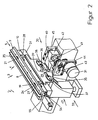
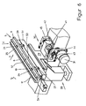
- Fig. 1 to 3 . 6 and 7 show means 1 for deforming a approximately evenly distributed on a Buckblockrücken aligned, optionally on the inside with a back insert, also called Schrenz, provided Buchdeckerücken 7 lying in the deformation lying out book cover 2, consisting essentially of two book covers and the book cover backs 7 forming middle part consists.
- the back insert is located between the covers of the book cover on the reference benefit and consists for example of cardboard or waste paper. Further relevant information can be found in DE 10'057 ⁇ 600, DE 10 ⁇ 057 ⁇ 602 or in the above-mentioned paperback book "Industrial Bookbinding".
- the Fig. 1 Figure 1 illustrates a device 1 according to the invention in an initial standby or rest position in which a deformation tool 3, designated 3, is set for the forthcoming deformation preferred for straight back formation.
- the deformation tool 3 which extends at least approximately over the length of a book height, is in the starting position at a distance below a book cover 2 for forming the Buchdecke Wegens 7 serving support level 48, which extends transversely to the conveying direction of the book block in a Ein distressmaschine (see, for example DE 1'436'086 A).
- the part of a device 1 forming deformation tool 3 consists of two facing, vertical resp.
- the tool bar 10 has approximately the length of the support strips 4, 5 and more than the width of the support strips at the largest web width. In the Fig. 2 . 3 and 6 the deformation tool 3 is in the raised position. Furthermore, the support surface 11 is provided as a management level of the tool bar 10 with sliding properties for the support strips 4, 5, so that thereon the skirting boards 8, 9 resp. let the support strips 4, 5 move easily.
- the tool bar 10 is used according to Fig.
- rotating bodies for example, about vertical axes 16, 17 drivable discs 12, 13, which are mounted in spaced along the tool carrier 10 recesses 14, 15 and at the top with respect to rotation axis 16, 17 respectively opposite drivers 18, 19; 20, 21.
- the discs 12, 13 are sunk in the tool bar 10 so that they do not touch the underside of the support strips 4, 5.
- the support strips 4, 5 have in theticianological Scheme parallel to the axis of rotation 16, 17 of the discs 12, 13 extending through openings 22, 23; 24, 25 or grooves, of the drivers 18, 19; 20, 21 are at least partially penetrated, wherein the drivers 18, 19; 20, 21 may be formed as stud bolts.
- a controller connected to a (controllable) motor can also be used.
- the on one side of the tool bar 10 above movement cam 27, 28 are by means of joints 32 or lateral guides with the oscillating on a frame 33, respectively.
- slidably mounted slide 29 connected.
- the support strips 4, 5 On the underside of the support strips 4, 5 has. This ensures that the support strips 4, 5 are adjustable transversely to the longitudinal extent of the deformation tool 3 exclusively.
- the deformation tool 3 is designed to be interchangeable, so that other support strips 4, 5 are used.
- the support strips 4, 5 can be exchanged on a deformation tool 3.
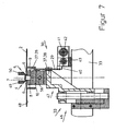
- Fig. 7 shows the arrangement between the deformation tool 3, which is also connected to the frame 33, and the sliding device 30, the slide 29 according to the execution of the Fig. 1 to 3 is connected to the deformation tool 3.
- the drive connected to the discs 12, 13, flat downwardly extending slide 29 has in the surface area a guide assembly for its displacement parallel to the longitudinal extension of the tool bar 10, on the one hand two spaced in the direction of displacement and extending in the latter slots 35, 36 and on the other a fixed to the frame 33, the slots 35, 36 associated and immersed in this sliding block 37, 38 on which the slider 29 is moved back and forth.
- a bottom-up reaching slot-like opening 39 for as Carrier trained drive cam 40 is provided which is indirectly connected to the drive motor 31.
- the slot-like opening 39 allows raising and lowering of the deformation tool 3 connected to the frame 33 Fig.
- the output shaft 41 is formed as a spindle, which intersperses a spindle nut of an adjusting 42 meshing, to which the drive cam 40 is fixed, and that on a rod 43 in the direction of the sliding movements of the slider 29 is guided.
- the 4 and 5 show the formation of the deformation tool 3 on the basis of a partial view / longitudinal section representation of the anti-slip connection between the top 11 of the tool bar 10, which rests on an intermediate element 51 designed as a heating element.
- the support strips 4, 5 may be provided on the underside, for example, with magnetic forces that generate large attraction forces on the top of the iron-containing tool bar 10.
- the support strips 4, 5 are in particular for the deformation processes at the bottom over the length of the skirting 8, 9 distributed equipped with permanent magnets 52 which are button-like and in the skirting boards 8, 9 are fixed interchangeably, for example by means of screw or adhesive.
- the magnetic surface of the permanent magnets 52 is preferably flush with the underside of the support strips 4, 5 resp. Skirts 8, 9 aligned, also on and off switchable electromagnets could be used instead of the permanent magnets.
- Known permanent magnets withstand temperatures up to 500 ° C.
- the support strips 4, 5 can be pressed over the skirting boards 8, 9 by means of screws and compression springs on the tool bar 10, wherein the support strips 4, 5 are screwed into the tool bar 10 inserted and displaceable sliding blocks.
- the in the Fig. 1 to 3 and 6 recognizable lift hook 54 is used for lifting or installation of a deformation tool 3 from the resp. in the device 1 by means of a hoist.
- a connected to the frame 33 conical positioning pin 55 is provided, which is locked under spring pressure in a designated hole on the front side of the tool bar 10.
- the intermediate element 51 is provided below the tool bar 10, which is equipped with heating elements 56 and from which the heat is transferred to the support strips 4, 5.
Landscapes
- Engineering & Computer Science (AREA)
- Manufacturing & Machinery (AREA)
- Mechanical Engineering (AREA)
- Perforating, Stamping-Out Or Severing By Means Other Than Cutting (AREA)
- Milling, Drilling, And Turning Of Wood (AREA)
- Specific Conveyance Elements (AREA)
Claims (22)
- Dispositif (1) pour façonner un dos de couverture (7) - aligné en étant approximativement uniformément réparti sur un dos de corps d'ouvrage et présentant éventuellement une garniture de dos sur le côté intérieur - d'une couverture d'ouvrage (2) positionnée en étant horizontalement déployée, constitué d'un outil de façonnage (3) pouvant être déplacé en direction du côté intérieur - tourné vers le dos de corps d'ouvrage - du dos de couverture (7), soulevant ce dos de couverture (7) entre deux rails latéraux opposés de formation de plis (49, 50) et formant un profil en U (6) sur le dos de couverture (7), outil qui présente deux barres de soutien voisines (4, 5) s'étendant parallèlement aux rails de formation de plis (49, 50), caractérisé en ce que les barres de soutien (4, 5) sont conçues conjointement mobiles transversalement à l'étendue longitudinale des rails de formation de plis (49, 50) de manière à modifier leur distance mutuelle afin de régler la largeur du profil en U du dos de couverture (7), et en ce que les barres de soutien (4, 5) reposent sur une barre d'outil (10) de l'outil de façonnage (3), barre qui présente sur le dessus un plan de guidage, et elles lui sont assemblées par adhérence ou par engagement positif, sachant que les barres de soutien (4, 5) sont respectivement accouplées à deux entraîneurs entraînés (18, 19 ; 20, 21).
- Dispositif selon la revendication 1, caractérisé en ce que les barres de soutien (4, 5) sont, en reposant dans un plan de guidage, respectivement accouplées aux deux entraîneurs (18, 19 ; 20, 21) espacés le long de leur étendue longitudinale et entraînés excentriquement en rotation autour d'un axe vertical (16, 17).
- Dispositif selon la revendication 2, caractérisé en ce que deux entraîneurs (18, 19 ; 20, 21) fixés sur un disque rotatif (12, 13) sont respectivement associés à un axe (16, 17).
- Dispositif selon la revendication 3, caractérisé en ce que les entraîneurs (18, 19 ; 20, 21) sont fixés sur le disque rotatif (12, 13) en étant mutuellement opposés par rapport à l'axe (16, 17).
- Dispositif selon la revendication 3 ou 4, caractérisé en ce que les disques (12, 13) sont montés dans une barre d'outil (10) de l'outil de façonnage (3).
- Dispositif selon l'une des revendications 1 à 5, caractérisé en ce que le plan de guidage est formé par une surface d'appui (11) sur la barre d'outil (10).
- Dispositif selon l'une des revendications 1 à 6, caractérisé en ce que les barres de soutien (4, 5) sont assemblées par adhérence ou par engagement positif à la surface d'appui (11) de la barre d'outil (10).
- Dispositif selon la revendication 7, caractérisé en ce que les barres de soutien (4, 5) sont assemblées par des forces magnétiques à la barre d'outil (10).
- Dispositif selon la revendication 8, caractérisé en ce que les barres de soutien (4, 5) présentent sur le dessous des aimants permanents (52) répartis sur la longueur, dont la surface agissant magnétiquement sur la barre d'outil (10) est respectivement alignée à fleur du dessous des barres de soutien (4, 5), respectivement des barres d'embase (8, 9) des barres de soutien (4, 5).
- Dispositif selon l'une des revendications 7 à 9, caractérisé en ce que la barre d'outil (10) présente une surface au moins partiellement magnétique, agissant sur les éléments de soutien (4, 5) contenant du fer.
- Dispositif selon l'une des revendications 3 à 10, caractérisé en ce que les disques rotatifs (12, 13) sont reliés en entraînement à un dispositif de translation (30).
- Dispositif selon l'une des revendications 3 à 11, caractérisé en ce que les disques (12, 13) sont respectivement rotatifs d'un angle aigu sur l'axe (16, 17).
- Dispositif selon l'une des revendications 3 à 12, caractérisé en ce que les disques (12, 13) présentent respectivement sur le pourtour une came de déplacement (27, 28) reliée au coulisseau (29).
- Dispositif selon l'une des revendications 3 à 13, caractérisé en ce que les disques rotatifs (12, 13) peuvent être séparés du dispositif de translation (30) en relevant la barre d'outil (10).
- Dispositif selon l'une des revendications 11 à 14, caractérisé en ce que le dispositif de translation (30) est relié à un entraînement à broche.
- Dispositif selon l'une des revendications 1 à 15, caractérisé en ce que les barres de soutien (4, 5) peuvent être déplacées dans un ensemble de guidage (34) s'étendant transversalement à leur étendue longitudinale.
- Dispositif selon la revendication 16, caractérisé en ce que l'ensemble de guidage (34) présente une rainure de guidage (53), s'étendant dans la barre d'outil (10) transversalement à l'étendue longitudinale des barres de soutien (4, 5) et destinée à recevoir une clavette de guidage (55) des barres de soutien (4, 5).
- Dispositif selon l'une des revendications 11 à 17, caractérisé en ce que les mouvements de déplacement du dispositif de translation (30) sont orientés parallèlement à l'étendue longitudinale des barres de soutien (4, 5).
- Dispositif selon l'une des revendications 11 à 18, caractérisé en ce qu'un coulisseau (29) du dispositif de translation (30) est guidé en translation dans un ensemble de translation (35, 37 ; 36, 38) fixé sur un bâti (33).
- Dispositif selon la revendication 19, caractérisé en ce que le coulisseau (29), qui fait saillie vers le bas, présente une ouverture (39) s'étendant verticalement dans laquelle parvient une came d'entraînement (40) d'un organe de déplacement (42) relié à l'entraînement à broche.
- Dispositif selon la revendication 20, caractérisé en ce que le coulisseau (29) est fixé à l'organe de déplacement (42).
- Dispositif selon l'une des revendications 5 à 21, caractérisé en ce que la barre d'outil (10) est disposée sur un élément chauffant réalisé sous forme d'élément intermédiaire (51).
Priority Applications (2)
| Application Number | Priority Date | Filing Date | Title |
|---|---|---|---|
| EP09405201.6A EP2325020B1 (fr) | 2009-11-23 | 2009-11-23 | Dispositif de déformation d'un dos de couverture de livre aligné sur un dos de bloc de livre d'une couverture de livre |
| US12/952,942 US8439621B2 (en) | 2009-11-23 | 2010-11-23 | Device for shaping a back of a book cover that is aligned with a book block spine |
Applications Claiming Priority (1)
| Application Number | Priority Date | Filing Date | Title |
|---|---|---|---|
| EP09405201.6A EP2325020B1 (fr) | 2009-11-23 | 2009-11-23 | Dispositif de déformation d'un dos de couverture de livre aligné sur un dos de bloc de livre d'une couverture de livre |
Publications (2)
| Publication Number | Publication Date |
|---|---|
| EP2325020A1 EP2325020A1 (fr) | 2011-05-25 |
| EP2325020B1 true EP2325020B1 (fr) | 2013-06-19 |
Family
ID=41728476
Family Applications (1)
| Application Number | Title | Priority Date | Filing Date |
|---|---|---|---|
| EP09405201.6A Active EP2325020B1 (fr) | 2009-11-23 | 2009-11-23 | Dispositif de déformation d'un dos de couverture de livre aligné sur un dos de bloc de livre d'une couverture de livre |
Country Status (2)
| Country | Link |
|---|---|
| US (1) | US8439621B2 (fr) |
| EP (1) | EP2325020B1 (fr) |
Families Citing this family (5)
| Publication number | Priority date | Publication date | Assignee | Title |
|---|---|---|---|---|
| DE102014004614A1 (de) * | 2014-03-29 | 2015-10-01 | Kolbus Gmbh & Co. Kg | Vorrichtung zum Formen von Buchdecken |
| JP2017136831A (ja) * | 2016-02-01 | 2017-08-10 | ミュラー・マルティニ・ホルディング・アクチエンゲゼルシヤフト | ブックブロックの予備成形及び丸味出しのための装置 |
| JP2017193176A (ja) | 2016-04-21 | 2017-10-26 | ミュラー・マルティニ・ホルディング・アクチエンゲゼルシヤフト | ブックカバーを変形させる変形工具のための予熱ステーション |
| EP3235654B1 (fr) | 2016-04-21 | 2019-01-30 | Müller Martini Holding AG | Outil de façonnage et dispositif de façonnage de couvertures de livre |
| JP2017193175A (ja) | 2016-04-21 | 2017-10-26 | ミュラー・マルティニ・ホルディング・アクチエンゲゼルシヤフト | ブックカバーを変形させるための装置 |
Citations (1)
| Publication number | Priority date | Publication date | Assignee | Title |
|---|---|---|---|---|
| DE102006033117A1 (de) * | 2006-07-18 | 2008-01-24 | Kolbus Gmbh & Co. Kg | Verfahren und Vorrichtung zur Schaffung einer scharnierartigen, biegbaren Zone in einem Bogen aus Papier, Pappe, Karton oder Folie |
Family Cites Families (14)
| Publication number | Priority date | Publication date | Assignee | Title |
|---|---|---|---|---|
| US2640208A (en) * | 1948-11-13 | 1953-06-02 | Florez Company Inc De | Method and apparatus for building in the cases of books |
| US3201810A (en) | 1962-10-04 | 1965-08-24 | Smyth Mfg Co | Heating means for casing-in machine |
| US3398038A (en) * | 1965-10-24 | 1968-08-20 | Crawford Jay | Book cover turning-in machine |
| GB1501443A (en) * | 1975-01-29 | 1978-02-15 | Korsgaard J | Method and apparatus for binding a book |
| US5203590A (en) * | 1990-10-31 | 1993-04-20 | Hertzberg-New Method, Inc. | Bound book with reinforced fabric strips |
| DE19729529B4 (de) * | 1996-09-13 | 2010-04-08 | Kolbus Gmbh & Co. Kg | Verfahren und Vorrichtung zum Herstellen eines Buches |
| US5980182A (en) * | 1998-06-23 | 1999-11-09 | Duplo Usa Corporation | Case-in device of adhesive bookbinder |
| DE19853254A1 (de) * | 1998-11-18 | 2000-05-25 | Kolbus Gmbh & Co Kg | Vorrichtung zum Runden von Buchdecken |
| US6364590B1 (en) * | 2000-08-01 | 2002-04-02 | Hewlett-Packard Company | Book cover preparation system |
| DE10057600B4 (de) | 2000-11-21 | 2008-10-09 | Kolbus Gmbh & Co. Kg | Vorrichtung zum Zuführen von Rückeneinlagen für das maschinelle Herstellen von Bucheinbanddecken |
| DE10057602C5 (de) | 2000-11-21 | 2014-09-11 | Kolbus Gmbh & Co. Kg | Vorrichtung zum Herstellen von Bucheinbanddecken |
| JP4760512B2 (ja) * | 2005-08-11 | 2011-08-31 | コニカミノルタビジネステクノロジーズ株式会社 | 製本装置 |
| DK1780038T3 (da) * | 2005-10-25 | 2011-04-11 | Mueller Martini Holding Ag | Indretning til fasttrykning af en bogafdækning på de limede udvendige flader af bogblokke med en separat drivindretning |
| JP4868933B2 (ja) * | 2006-05-02 | 2012-02-01 | ニスカ株式会社 | 製本装置及びこれを備えた画像形成装置 |
-
2009
- 2009-11-23 EP EP09405201.6A patent/EP2325020B1/fr active Active
-
2010
- 2010-11-23 US US12/952,942 patent/US8439621B2/en active Active
Patent Citations (1)
| Publication number | Priority date | Publication date | Assignee | Title |
|---|---|---|---|---|
| DE102006033117A1 (de) * | 2006-07-18 | 2008-01-24 | Kolbus Gmbh & Co. Kg | Verfahren und Vorrichtung zur Schaffung einer scharnierartigen, biegbaren Zone in einem Bogen aus Papier, Pappe, Karton oder Folie |
Also Published As
| Publication number | Publication date |
|---|---|
| EP2325020A1 (fr) | 2011-05-25 |
| US20110123298A1 (en) | 2011-05-26 |
| US8439621B2 (en) | 2013-05-14 |
Similar Documents
| Publication | Publication Date | Title |
|---|---|---|
| EP2392438B1 (fr) | Dispositif de traitement | |
| EP2139634B1 (fr) | Dispositif de coupe | |
| EP2325020B1 (fr) | Dispositif de déformation d'un dos de couverture de livre aligné sur un dos de bloc de livre d'une couverture de livre | |
| AT516708B1 (de) | Auflagetisch für Biegemaschine | |
| EP2923852B1 (fr) | Dispositif de formage de couvertures de livre | |
| EP2949437B1 (fr) | Dispositif de raclage | |
| EP3112083B1 (fr) | Système de portique d'une machine-outil et machine-outil avec un tel système de portique | |
| DE202020002598U1 (de) | Biegemaschine zum Biegen eines Werkstücks aus Flachmaterial und Steuereinheit für eine solche Biegemaschine | |
| EP1780038B2 (fr) | Dispositif pour le broyage d'une couverture sur un dos collé de bloc de livre avec un entraînement séparé | |
| EP2191948B1 (fr) | Dispositif pour travailler les côtés de panneaux | |
| EP3406456B1 (fr) | Encolleuse | |
| EP3235653B1 (fr) | Station de préchauffage pour un outil de façonnage de couvertures de livre | |
| EP3235654B1 (fr) | Outil de façonnage et dispositif de façonnage de couvertures de livre | |
| EP2347912B1 (fr) | Dispositif de déformation d'une couverture de livre | |
| EP3235652B1 (fr) | Dispositif de façonnage de couvertures de livre | |
| EP2277710B1 (fr) | Dispositif de déformation d'un dos de couverture de livre aligné sur un dos de bloc de livre d'une couverture de livre | |
| EP2650138B1 (fr) | Machine pour former et presser des livres | |
| WO2011054488A1 (fr) | Unité de fermeture pour une machine de moulage par injection | |
| EP3199369B1 (fr) | Procédé destiné à préformer et à arrondir une tranche de livre | |
| AT516434B1 (de) | Endbearbeitungsaggregat mit lageverstellbarer Kopiereinrichtung | |
| EP2650139B1 (fr) | Machine pour former et presser des livres | |
| EP3527341B1 (fr) | Dispositif ainsi que procédé de mise en uvre d'au moins un processus de coupe | |
| EP2711192B1 (fr) | Dispositif destiné à l'installation d'un bloc de livre | |
| DE19514395C2 (de) | Verfahren zum Handhaben eines Blattstapels und Vorrichtung zur Ausführung dieses Verfahrens | |
| EP2347913B1 (fr) | Dispositif pour le formage de couvertures de livres |
Legal Events
| Date | Code | Title | Description |
|---|---|---|---|
| PUAI | Public reference made under article 153(3) epc to a published international application that has entered the european phase |
Free format text: ORIGINAL CODE: 0009012 |
|
| AK | Designated contracting states |
Kind code of ref document: A1 Designated state(s): AT BE BG CH CY CZ DE DK EE ES FI FR GB GR HR HU IE IS IT LI LT LU LV MC MK MT NL NO PL PT RO SE SI SK SM TR |
|
| AX | Request for extension of the european patent |
Extension state: AL BA RS |
|
| 17P | Request for examination filed |
Effective date: 20110830 |
|
| 17Q | First examination report despatched |
Effective date: 20110919 |
|
| GRAP | Despatch of communication of intention to grant a patent |
Free format text: ORIGINAL CODE: EPIDOSNIGR1 |
|
| GRAP | Despatch of communication of intention to grant a patent |
Free format text: ORIGINAL CODE: EPIDOSNIGR1 |
|
| INTG | Intention to grant announced |
Effective date: 20130402 |
|
| GRAS | Grant fee paid |
Free format text: ORIGINAL CODE: EPIDOSNIGR3 |
|
| GRAA | (expected) grant |
Free format text: ORIGINAL CODE: 0009210 |
|
| AK | Designated contracting states |
Kind code of ref document: B1 Designated state(s): AT BE BG CH CY CZ DE DK EE ES FI FR GB GR HR HU IE IS IT LI LT LU LV MC MK MT NL NO PL PT RO SE SI SK SM TR |
|
| REG | Reference to a national code |
Ref country code: GB Ref legal event code: FG4D Free format text: NOT ENGLISH |
|
| REG | Reference to a national code |
Ref country code: CH Ref legal event code: EP |
|
| REG | Reference to a national code |
Ref country code: AT Ref legal event code: REF Ref document number: 617423 Country of ref document: AT Kind code of ref document: T Effective date: 20130715 |
|
| REG | Reference to a national code |
Ref country code: IE Ref legal event code: FG4D Free format text: LANGUAGE OF EP DOCUMENT: GERMAN |
|
| REG | Reference to a national code |
Ref country code: DE Ref legal event code: R096 Ref document number: 502009007366 Country of ref document: DE Effective date: 20130814 |
|
| PG25 | Lapsed in a contracting state [announced via postgrant information from national office to epo] |
Ref country code: SE Free format text: LAPSE BECAUSE OF FAILURE TO SUBMIT A TRANSLATION OF THE DESCRIPTION OR TO PAY THE FEE WITHIN THE PRESCRIBED TIME-LIMIT Effective date: 20130619 Ref country code: SI Free format text: LAPSE BECAUSE OF FAILURE TO SUBMIT A TRANSLATION OF THE DESCRIPTION OR TO PAY THE FEE WITHIN THE PRESCRIBED TIME-LIMIT Effective date: 20130619 Ref country code: FI Free format text: LAPSE BECAUSE OF FAILURE TO SUBMIT A TRANSLATION OF THE DESCRIPTION OR TO PAY THE FEE WITHIN THE PRESCRIBED TIME-LIMIT Effective date: 20130619 Ref country code: ES Free format text: LAPSE BECAUSE OF FAILURE TO SUBMIT A TRANSLATION OF THE DESCRIPTION OR TO PAY THE FEE WITHIN THE PRESCRIBED TIME-LIMIT Effective date: 20130930 Ref country code: LT Free format text: LAPSE BECAUSE OF FAILURE TO SUBMIT A TRANSLATION OF THE DESCRIPTION OR TO PAY THE FEE WITHIN THE PRESCRIBED TIME-LIMIT Effective date: 20130619 Ref country code: NO Free format text: LAPSE BECAUSE OF FAILURE TO SUBMIT A TRANSLATION OF THE DESCRIPTION OR TO PAY THE FEE WITHIN THE PRESCRIBED TIME-LIMIT Effective date: 20130919 Ref country code: GR Free format text: LAPSE BECAUSE OF FAILURE TO SUBMIT A TRANSLATION OF THE DESCRIPTION OR TO PAY THE FEE WITHIN THE PRESCRIBED TIME-LIMIT Effective date: 20130920 |
|
| REG | Reference to a national code |
Ref country code: LT Ref legal event code: MG4D |
|
| PG25 | Lapsed in a contracting state [announced via postgrant information from national office to epo] |
Ref country code: HR Free format text: LAPSE BECAUSE OF FAILURE TO SUBMIT A TRANSLATION OF THE DESCRIPTION OR TO PAY THE FEE WITHIN THE PRESCRIBED TIME-LIMIT Effective date: 20130619 Ref country code: BG Free format text: LAPSE BECAUSE OF FAILURE TO SUBMIT A TRANSLATION OF THE DESCRIPTION OR TO PAY THE FEE WITHIN THE PRESCRIBED TIME-LIMIT Effective date: 20130919 |
|
| REG | Reference to a national code |
Ref country code: NL Ref legal event code: VDEP Effective date: 20130619 |
|
| PG25 | Lapsed in a contracting state [announced via postgrant information from national office to epo] |
Ref country code: LV Free format text: LAPSE BECAUSE OF FAILURE TO SUBMIT A TRANSLATION OF THE DESCRIPTION OR TO PAY THE FEE WITHIN THE PRESCRIBED TIME-LIMIT Effective date: 20130619 |
|
| PG25 | Lapsed in a contracting state [announced via postgrant information from national office to epo] |
Ref country code: PT Free format text: LAPSE BECAUSE OF FAILURE TO SUBMIT A TRANSLATION OF THE DESCRIPTION OR TO PAY THE FEE WITHIN THE PRESCRIBED TIME-LIMIT Effective date: 20131021 Ref country code: CY Free format text: LAPSE BECAUSE OF FAILURE TO SUBMIT A TRANSLATION OF THE DESCRIPTION OR TO PAY THE FEE WITHIN THE PRESCRIBED TIME-LIMIT Effective date: 20130717 Ref country code: EE Free format text: LAPSE BECAUSE OF FAILURE TO SUBMIT A TRANSLATION OF THE DESCRIPTION OR TO PAY THE FEE WITHIN THE PRESCRIBED TIME-LIMIT Effective date: 20130619 Ref country code: CZ Free format text: LAPSE BECAUSE OF FAILURE TO SUBMIT A TRANSLATION OF THE DESCRIPTION OR TO PAY THE FEE WITHIN THE PRESCRIBED TIME-LIMIT Effective date: 20130619 Ref country code: SK Free format text: LAPSE BECAUSE OF FAILURE TO SUBMIT A TRANSLATION OF THE DESCRIPTION OR TO PAY THE FEE WITHIN THE PRESCRIBED TIME-LIMIT Effective date: 20130619 Ref country code: IS Free format text: LAPSE BECAUSE OF FAILURE TO SUBMIT A TRANSLATION OF THE DESCRIPTION OR TO PAY THE FEE WITHIN THE PRESCRIBED TIME-LIMIT Effective date: 20131019 |
|
| PG25 | Lapsed in a contracting state [announced via postgrant information from national office to epo] |
Ref country code: NL Free format text: LAPSE BECAUSE OF FAILURE TO SUBMIT A TRANSLATION OF THE DESCRIPTION OR TO PAY THE FEE WITHIN THE PRESCRIBED TIME-LIMIT Effective date: 20130619 Ref country code: PL Free format text: LAPSE BECAUSE OF FAILURE TO SUBMIT A TRANSLATION OF THE DESCRIPTION OR TO PAY THE FEE WITHIN THE PRESCRIBED TIME-LIMIT Effective date: 20130619 Ref country code: RO Free format text: LAPSE BECAUSE OF FAILURE TO SUBMIT A TRANSLATION OF THE DESCRIPTION OR TO PAY THE FEE WITHIN THE PRESCRIBED TIME-LIMIT Effective date: 20130619 |
|
| PG25 | Lapsed in a contracting state [announced via postgrant information from national office to epo] |
Ref country code: CY Free format text: LAPSE BECAUSE OF FAILURE TO SUBMIT A TRANSLATION OF THE DESCRIPTION OR TO PAY THE FEE WITHIN THE PRESCRIBED TIME-LIMIT Effective date: 20130619 |
|
| PLBE | No opposition filed within time limit |
Free format text: ORIGINAL CODE: 0009261 |
|
| STAA | Information on the status of an ep patent application or granted ep patent |
Free format text: STATUS: NO OPPOSITION FILED WITHIN TIME LIMIT |
|
| PG25 | Lapsed in a contracting state [announced via postgrant information from national office to epo] |
Ref country code: DK Free format text: LAPSE BECAUSE OF FAILURE TO SUBMIT A TRANSLATION OF THE DESCRIPTION OR TO PAY THE FEE WITHIN THE PRESCRIBED TIME-LIMIT Effective date: 20130619 |
|
| 26N | No opposition filed |
Effective date: 20140320 |
|
| BERE | Be: lapsed |
Owner name: MULLER MARTINI HOLDING A.G. Effective date: 20131130 |
|
| REG | Reference to a national code |
Ref country code: DE Ref legal event code: R097 Ref document number: 502009007366 Country of ref document: DE Effective date: 20140320 |
|
| GBPC | Gb: european patent ceased through non-payment of renewal fee |
Effective date: 20131123 |
|
| PG25 | Lapsed in a contracting state [announced via postgrant information from national office to epo] |
Ref country code: MC Free format text: LAPSE BECAUSE OF FAILURE TO SUBMIT A TRANSLATION OF THE DESCRIPTION OR TO PAY THE FEE WITHIN THE PRESCRIBED TIME-LIMIT Effective date: 20130619 |
|
| REG | Reference to a national code |
Ref country code: FR Ref legal event code: ST Effective date: 20140731 |
|
| REG | Reference to a national code |
Ref country code: IE Ref legal event code: MM4A |
|
| PG25 | Lapsed in a contracting state [announced via postgrant information from national office to epo] |
Ref country code: BE Free format text: LAPSE BECAUSE OF NON-PAYMENT OF DUE FEES Effective date: 20131130 |
|
| PG25 | Lapsed in a contracting state [announced via postgrant information from national office to epo] |
Ref country code: IE Free format text: LAPSE BECAUSE OF NON-PAYMENT OF DUE FEES Effective date: 20131123 |
|
| PG25 | Lapsed in a contracting state [announced via postgrant information from national office to epo] |
Ref country code: GB Free format text: LAPSE BECAUSE OF NON-PAYMENT OF DUE FEES Effective date: 20131123 Ref country code: FR Free format text: LAPSE BECAUSE OF NON-PAYMENT OF DUE FEES Effective date: 20131202 |
|
| PG25 | Lapsed in a contracting state [announced via postgrant information from national office to epo] |
Ref country code: SM Free format text: LAPSE BECAUSE OF FAILURE TO SUBMIT A TRANSLATION OF THE DESCRIPTION OR TO PAY THE FEE WITHIN THE PRESCRIBED TIME-LIMIT Effective date: 20130619 |
|
| PG25 | Lapsed in a contracting state [announced via postgrant information from national office to epo] |
Ref country code: TR Free format text: LAPSE BECAUSE OF FAILURE TO SUBMIT A TRANSLATION OF THE DESCRIPTION OR TO PAY THE FEE WITHIN THE PRESCRIBED TIME-LIMIT Effective date: 20130619 |
|
| PG25 | Lapsed in a contracting state [announced via postgrant information from national office to epo] |
Ref country code: MK Free format text: LAPSE BECAUSE OF FAILURE TO SUBMIT A TRANSLATION OF THE DESCRIPTION OR TO PAY THE FEE WITHIN THE PRESCRIBED TIME-LIMIT Effective date: 20130619 Ref country code: HU Free format text: LAPSE BECAUSE OF FAILURE TO SUBMIT A TRANSLATION OF THE DESCRIPTION OR TO PAY THE FEE WITHIN THE PRESCRIBED TIME-LIMIT; INVALID AB INITIO Effective date: 20091123 Ref country code: LU Free format text: LAPSE BECAUSE OF NON-PAYMENT OF DUE FEES Effective date: 20131123 |
|
| PG25 | Lapsed in a contracting state [announced via postgrant information from national office to epo] |
Ref country code: MT Free format text: LAPSE BECAUSE OF FAILURE TO SUBMIT A TRANSLATION OF THE DESCRIPTION OR TO PAY THE FEE WITHIN THE PRESCRIBED TIME-LIMIT Effective date: 20130619 |
|
| REG | Reference to a national code |
Ref country code: AT Ref legal event code: MM01 Ref document number: 617423 Country of ref document: AT Kind code of ref document: T Effective date: 20141123 |
|
| PG25 | Lapsed in a contracting state [announced via postgrant information from national office to epo] |
Ref country code: AT Free format text: LAPSE BECAUSE OF NON-PAYMENT OF DUE FEES Effective date: 20141123 |
|
| PGFP | Annual fee paid to national office [announced via postgrant information from national office to epo] |
Ref country code: CH Payment date: 20200221 Year of fee payment: 11 |
|
| REG | Reference to a national code |
Ref country code: CH Ref legal event code: PL |
|
| PG25 | Lapsed in a contracting state [announced via postgrant information from national office to epo] |
Ref country code: LI Free format text: LAPSE BECAUSE OF NON-PAYMENT OF DUE FEES Effective date: 20201130 Ref country code: CH Free format text: LAPSE BECAUSE OF NON-PAYMENT OF DUE FEES Effective date: 20201130 |
|
| PGFP | Annual fee paid to national office [announced via postgrant information from national office to epo] |
Ref country code: DE Payment date: 20251201 Year of fee payment: 17 |
|
| PGFP | Annual fee paid to national office [announced via postgrant information from national office to epo] |
Ref country code: IT Payment date: 20251127 Year of fee payment: 17 |