EP2325539A1 - Collier multifonctions - Google Patents
Collier multifonctions Download PDFInfo
- Publication number
- EP2325539A1 EP2325539A1 EP10161787A EP10161787A EP2325539A1 EP 2325539 A1 EP2325539 A1 EP 2325539A1 EP 10161787 A EP10161787 A EP 10161787A EP 10161787 A EP10161787 A EP 10161787A EP 2325539 A1 EP2325539 A1 EP 2325539A1
- Authority
- EP
- European Patent Office
- Prior art keywords
- receiving
- mounting part
- pipe clamp
- mounting
- receiving part
- Prior art date
- Legal status (The legal status is an assumption and is not a legal conclusion. Google has not performed a legal analysis and makes no representation as to the accuracy of the status listed.)
- Granted
Links
Images



Classifications
-
- F—MECHANICAL ENGINEERING; LIGHTING; HEATING; WEAPONS; BLASTING
- F16—ENGINEERING ELEMENTS AND UNITS; GENERAL MEASURES FOR PRODUCING AND MAINTAINING EFFECTIVE FUNCTIONING OF MACHINES OR INSTALLATIONS; THERMAL INSULATION IN GENERAL
- F16L—PIPES; JOINTS OR FITTINGS FOR PIPES; SUPPORTS FOR PIPES, CABLES OR PROTECTIVE TUBING; MEANS FOR THERMAL INSULATION IN GENERAL
- F16L3/00—Supports for pipes, cables or protective tubing, e.g. hangers, holders, clamps, cleats, clips, brackets
- F16L3/08—Supports for pipes, cables or protective tubing, e.g. hangers, holders, clamps, cleats, clips, brackets substantially surrounding the pipe, cable or protective tubing
- F16L3/10—Supports for pipes, cables or protective tubing, e.g. hangers, holders, clamps, cleats, clips, brackets substantially surrounding the pipe, cable or protective tubing divided, i.e. with two members engaging the pipe, cable or protective tubing
- F16L3/1008—Supports for pipes, cables or protective tubing, e.g. hangers, holders, clamps, cleats, clips, brackets substantially surrounding the pipe, cable or protective tubing divided, i.e. with two members engaging the pipe, cable or protective tubing with two members engaging the pipe, cable or tubing, both being made of thin band material completely surrounding the pipe
- F16L3/1025—Supports for pipes, cables or protective tubing, e.g. hangers, holders, clamps, cleats, clips, brackets substantially surrounding the pipe, cable or protective tubing divided, i.e. with two members engaging the pipe, cable or protective tubing with two members engaging the pipe, cable or tubing, both being made of thin band material completely surrounding the pipe the members being joined by quick-acting means
-
- F—MECHANICAL ENGINEERING; LIGHTING; HEATING; WEAPONS; BLASTING
- F16—ENGINEERING ELEMENTS AND UNITS; GENERAL MEASURES FOR PRODUCING AND MAINTAINING EFFECTIVE FUNCTIONING OF MACHINES OR INSTALLATIONS; THERMAL INSULATION IN GENERAL
- F16L—PIPES; JOINTS OR FITTINGS FOR PIPES; SUPPORTS FOR PIPES, CABLES OR PROTECTIVE TUBING; MEANS FOR THERMAL INSULATION IN GENERAL
- F16L3/00—Supports for pipes, cables or protective tubing, e.g. hangers, holders, clamps, cleats, clips, brackets
- F16L3/08—Supports for pipes, cables or protective tubing, e.g. hangers, holders, clamps, cleats, clips, brackets substantially surrounding the pipe, cable or protective tubing
- F16L3/10—Supports for pipes, cables or protective tubing, e.g. hangers, holders, clamps, cleats, clips, brackets substantially surrounding the pipe, cable or protective tubing divided, i.e. with two members engaging the pipe, cable or protective tubing
- F16L3/11—Supports for pipes, cables or protective tubing, e.g. hangers, holders, clamps, cleats, clips, brackets substantially surrounding the pipe, cable or protective tubing divided, i.e. with two members engaging the pipe, cable or protective tubing and hanging from a pendant
-
- F—MECHANICAL ENGINEERING; LIGHTING; HEATING; WEAPONS; BLASTING
- F16—ENGINEERING ELEMENTS AND UNITS; GENERAL MEASURES FOR PRODUCING AND MAINTAINING EFFECTIVE FUNCTIONING OF MACHINES OR INSTALLATIONS; THERMAL INSULATION IN GENERAL
- F16L—PIPES; JOINTS OR FITTINGS FOR PIPES; SUPPORTS FOR PIPES, CABLES OR PROTECTIVE TUBING; MEANS FOR THERMAL INSULATION IN GENERAL
- F16L3/00—Supports for pipes, cables or protective tubing, e.g. hangers, holders, clamps, cleats, clips, brackets
- F16L3/24—Supports for pipes, cables or protective tubing, e.g. hangers, holders, clamps, cleats, clips, brackets with special member for attachment to profiled girders
- F16L3/243—Supports for pipes, cables or protective tubing, e.g. hangers, holders, clamps, cleats, clips, brackets with special member for attachment to profiled girders the special member being inserted in the profiled girder
-
- F—MECHANICAL ENGINEERING; LIGHTING; HEATING; WEAPONS; BLASTING
- F16—ENGINEERING ELEMENTS AND UNITS; GENERAL MEASURES FOR PRODUCING AND MAINTAINING EFFECTIVE FUNCTIONING OF MACHINES OR INSTALLATIONS; THERMAL INSULATION IN GENERAL
- F16L—PIPES; JOINTS OR FITTINGS FOR PIPES; SUPPORTS FOR PIPES, CABLES OR PROTECTIVE TUBING; MEANS FOR THERMAL INSULATION IN GENERAL
- F16L55/00—Devices or appurtenances for use in, or in connection with, pipes or pipe systems
- F16L55/02—Energy absorbers; Noise absorbers
- F16L55/033—Noise absorbers
- F16L55/035—Noise absorbers in the form of specially adapted hangers or supports
-
- F—MECHANICAL ENGINEERING; LIGHTING; HEATING; WEAPONS; BLASTING
- F16—ENGINEERING ELEMENTS AND UNITS; GENERAL MEASURES FOR PRODUCING AND MAINTAINING EFFECTIVE FUNCTIONING OF MACHINES OR INSTALLATIONS; THERMAL INSULATION IN GENERAL
- F16L—PIPES; JOINTS OR FITTINGS FOR PIPES; SUPPORTS FOR PIPES, CABLES OR PROTECTIVE TUBING; MEANS FOR THERMAL INSULATION IN GENERAL
- F16L59/00—Thermal insulation in general
- F16L59/12—Arrangements for supporting insulation from the wall or body insulated, e.g. by means of spacers between pipe and heat-insulating material; Arrangements specially adapted for supporting insulated bodies
- F16L59/135—Hangers or supports specially adapted for insulated pipes
-
- H—ELECTRICITY
- H02—GENERATION; CONVERSION OR DISTRIBUTION OF ELECTRIC POWER
- H02G—INSTALLATION OF ELECTRIC CABLES OR LINES, OR OF COMBINED OPTICAL AND ELECTRIC CABLES OR LINES
- H02G3/00—Installations of electric cables or lines or protective tubing therefor in or on buildings, equivalent structures or vehicles
- H02G3/30—Installations of cables or lines on walls, floors or ceilings
- H02G3/32—Installations of cables or lines on walls, floors or ceilings using mounting clamps
Definitions
- the invention relates to a pipe clamp according to the preamble of patent claim 1.
- Pipe clamps are used for the installation of pipes, in particular pipes, which are to be firmly connected to a building and to be kept stable at a mounting position.
- Part 12 of the standard DIN 4102 describes the requirements, tests and measures for achieving the functional integrity of electrical cable systems in case of fire. This standard thus enables the testing of a complete cable system under practical conditions. These include insulated power lines, installation lines for telecommunications and information processing equipment, pipes and related fasteners, carrying devices and brackets.
- a pipe clamp which has a plate-shaped mounting part with a receiving a conduit receiving part, which is connectable to two end pieces by means of screws with end pieces of a metal terminating element, through which the installed pipe is enclosed in the pipe clamp.
- the mounting part is usually connected in horizontal alignment, for example with a rail.
- Other mounting options such as the installation of this clamp on a wall, on the ceiling or on the floor, are not given.
- WO 0104529 A1 is known a clamping device with screwable elements, by means of which lines can be installed.
- this clamping device which is hardly suitable for the installation of pipes, but offers no convenient installation options and no advantageous handling of the cables to be installed.
- FR 2214343 A5 Clamps are shown in elementary configurations.
- Connecting devices which have only a metal receiving part on which the cable is fixed by means of a cable tie.
- these pipe clamps are mounted horizontally with the receiving part open at the top. If these pipe clamps are mounted on the wall or the ceiling, the cable is not held in the receiving part, so it must be fixed with the cable tie, which releases the line in case of fire.
- a clamping device is known by means of the cables can be mounted without screws are required.
- a mounting part is provided, which has a U-shaped recess in the the line is inserted.
- at least one toothing is provided, in which the toothing of a wedge can engage.
- the wedge is inserted under force into the recess, after which the inserted line is deformed and the teeth firmly intermesh.
- This clamping device has significant disadvantages with regard to the desired types of installation. If the line is not deformed sufficiently strongly, there is a risk that the teeth will be disengaged.
- a pipe clamp which consists of a versatile mountable system part, in which a line is inserted, which is fixed by means of a cable tie or a hold-down. In case of fire, a deformation of the system part and the cable tie may result. Furthermore, it would be desirable in this clamp, to facilitate the installation of the lines on. In particular, it would be desirable if conduits and tubes with minimal Expenditure, especially on a trial basis, could be mounted quickly and safely.
- the present invention is therefore an object of the invention to provide an improved pipe clamp, which ensures a secure hold an installed pipe or pipe even in case of fire.
- the installation process should be carried out quickly and conveniently, so that an installation, in particular a temporary installation, which ensures a secure holding a pipe or a pipe, and the corresponding deinstallation are possible with just a handle.
- the pipe clamp which allows for a fire-proof installation of a pipe, in particular a pipe, comprises a mounting part and a receiving part, which are integrally formed from a metal sheet and connectable to each other and serve to hold the installed line.
- the U-shaped mounting part comprises a base plate provided with at least one mounting element and two side walls.
- the receiving part has a holding the line serving and at least approximately V-shaped receiving segment and on both sides outwardly projecting connecting elements which engage positively each in an opening in the side walls of the mounting part, between which the receiving part selectively facing the mounting part or from this is facing away mountable.
- the manufacture of the mounting part and the receiving part in one piece from a metal sheet is possible with little effort on material and work.
- a starting material is used, which has a high fire resistance.
- stainless steel sheets or normal or high-temperature steels are used, which are provided with a protective layer, such as zinc.
- U-profile for the mounting part is particularly advantageous in terms of fire.
- a U-profile preferably a U-profile with reinforced base plate, instead of deformation, only an expansion of the mounting part, which is not critical to the functional integrity of the pipe clamp.
- An effective reinforcement of the base plate, even with thin sheet metal can be realized by the embossing of beads, which give the base plate to a multiple higher bending stiffness.
- the choice of a receiving part with an at least approximately V-shaped receiving segment allows to accommodate pipes and pipes of different diameters and to keep stable.
- the pipes and pipes are therefore on the receiving segment and not on the mounting part.
- the on the receiving part on both sides outwardly projecting connecting elements, which can positively engage each in an opening in the side walls of the mounting part, allow to mount the receiving part with a handle in the mounting part.
- the mounting part and the receiving part are dimensioned and configured such that the receiving part can be selectively connected to the receiving part facing the mounting part or facing away from this with the mounting part. This opens up numerous advantageous possibilities for mounting the pipe clamp and for handling a cable to be installed.
- the mounting part is preferably mounted with only one mounting screw, which e.g. is connected by means of nuts with the base plate of the mounting part.
- the mounting screw for example a threaded rod or a concrete anchor, can be anchored in the ceiling, a wall or in the floor of a room or on any side of an object.
- the ability to selectively insert the receiving part now allows the conduit or pipe to be installed in a convenient manner. If the mounting part mounted on the floor or on an object is opened upwards, the receiving part can be inserted with the receiving segment facing the mounting part into the mounting part. Subsequently, the line can be placed on the receiving segment, so that it is supported by the receiving segment. If the mounted on the ceiling mounting part is open downwards, the receiving part is mounted with the receiving part facing away from the mounting part in the mounting part. In both freely selectable installation variants, the receiving part or the receiving part can be installed together with the line with a handle.
- the fixation of the line can be done in various ways.
- cable ties are used, which connect the installed cable firmly with the receiving part.
- a metal closure member such as a U-shaped or L-shaped bracket may be used.
- the pipe clamp can therefore be used so flexibly that virtually all relevant installation requirements can be taken into account with a single pipe clamp.
- the receiving part has two adjoining the receiving segment and at least approximately parallel side pieces, which are provided with outwardly directed hooks which engage through the preferably rectangular openings in the side walls of the mounting part.
- the two side pieces abut against the side walls of the mounting part, after the connecting elements serving as hooks were inserted into the openings.
- the two side pieces of the receiving part are provided in addition to the hooks with outwardly directed locking elements which are arranged such that they protrude on the side in the openings in the side walls of the mounting part, which is opposite to the side of the openings on the the hooks rest.
- the locking elements ensures that the hooks can not solve themselves from the openings.
- the locking elements can be released and the receiving part can be unhooked from the mounting part.
- connection which can be additionally secured by the side pieces of the receiving part and the side walls of the mounting part, which are preferably designed plate-shaped and at least approximately parallel to each other abutment, for example, by means of screwing pressed against each other.
- This additional backup is realized according to the invention by means of a fixation of the line serving retaining clip, which is provided on both sides each with a retaining screw through which presses each side wall of the mounting member against the corresponding side piece of the receiving part and the headband. After mounting the retaining clip, the side walls and the side pieces abut each other, which is why the locking element is held in the opening and the hook can not be solved.
- By mounting the retaining bracket also results in a second, at least positive connection between the mounting part and the receiving part.
- An additional positive connection can be achieved by providing the side walls and the side pieces with intermeshing deformations. The installed pipe clamp is thus protected twice after installation to avoid a fire in case of fire separation.
- the retaining bracket comprises a voltage applied to the installed line hold-down and at least one side member which is provided with an opening or a threaded bore through which a retaining screw is guided, by means of which the headband is connected at least to the receiving part and / or the mounting part.
- the side walls of the mounting part preferably have separate openings which are self-contained. In the first openings in the side walls therefore engage the hook and the locking elements of the receiving part.
- the retaining screws of the retaining clip are guided such that the headband along the side walls of the mounting member can be guided upwards and downwards.
- the second opening which is preferably designed as a longitudinal slot, runs near the base plate, preferably in a curve, which makes it possible to guide the retaining bracket into a parking space to the side and to fix it there. If the headband is rotated in addition to the side, the space below the base plate is released, so that can be accessed with a tool on the mounting screw. After installing the pipe clamp, the headband can be loosened, turned and driven against the pipe.
- the side pieces of the receiving part have on the side facing away from the receiving segment depending on an outwardly open mounting slot, which runs parallel to the second opening in the associated side wall of the mounting part.
- the retaining screws can therefore be moved out of the parking space and driven along the associated longitudinal slot in the side walls of the mounting part in the open to the outside mounting slots in the side pieces of the receiving part.
- the side pieces of the receiving part are preferably exposed, so that the headband can be inserted into the receiving part by the retaining screws are inserted into the mounting slots.
- the receiving segment of the receiving part and the hold-down part of the retaining clip are preferably provided with at least one elastic element.
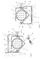
- FIGS. 1a-1d show a pipe clamp 1 according to the invention, which comprises a mounting part 12 and a receiving part 11, which are made in one piece from a metal sheet and without screws positively connected with each other and are releasable again.
- the mounting part 12 is formed into a U-profile and comprises a base plate 122 provided with a mounting opening 125 and two side walls 121 adjoining on both sides thereof, 123.
- the receiving part 11 comprises a holding the line 6 serving and at least approximately V-shaped receiving segment 111 and on both sides outwardly projecting connecting elements 112 which are arranged on at least approximately mutually parallel side pieces 110 of the receiving part 11.
- the connecting elements 112 engage positively each in an opening 126 in the side walls 121, 123 of the mounting part 12, between which the receiving part 11 either with the receiving segment 111 facing the mounting part 12 or facing away from this receiving segment 111 can be mounted.
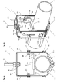
- FIGS. 3a and 3b show a pipe clamp 1 according to the invention in a further preferred embodiment, in which in turn a mounting part 12 and a receiving part 11 are provided, which in turn by connecting elements 112; 1121, 1122 and 126 are positively connected with each other. Furthermore, a closure element 2 is provided in the embodiment of a retaining clip, by means of which an installed line 6 is fixed.
- the U-shaped mounting member 12 which in the Figures 7a, 7b and 7c is shown isolated, is made of a thin sheet metal and has a base plate 122 to which a perpendicular thereto aligned side wall 121 and 123 connects on each side.
- the base plate 123 is provided with two reinforcing beads 1221 extending from one to the other side wall 121, 123. Between the two beads 1221, the mounting hole 125 is provided, in which a mounting screw 91 or a threaded anchor is fastened by means of nuts 92.
- the beads 1221 ensures that the thin base plate 122 can not bend even under the influence of load in case of fire. Despite the low material thickness, the base plate therefore has a high flexural strength.
- the side walls 121, 123 of the mounting part 12 are loaded only on train and do not bend under load even in case of fire, could be dispensed with the formation of beads.
- the side walls 121, 123 have on the underside a rectangular first opening 126 and closer to the base plate 122 a slot-shaped second opening 1260 which has the shape of an "L" whose foot element faces the base plate 122 and forms a parking space 1261.
- a hook-shaped connecting element 1121 and a locking element 1122 are held, which are each arranged on a side piece 110 of the receiving part 11.
- each a retaining screw 81 is guided, by means of which a headband 2 between the side walls 121, 123 and held along the second opening 1260, down against the installed line 6 and up to the parking space 1260 each retaining screw 81 is mobile.
- the in Figure 7a shown separately has a U-profile with a hold-down 21, connect to the both sides by 90 ° angled side elements 22, which are each provided with a threaded hole 220, in which engage the two retaining screw 81.
- the parking space 1261 of the second opening 1260 and the side members 22 of the retaining clip 2 allow the hold-down member 21 provided with an elastic member 28 to move sideways and pivot so as to expose the space below the base plate 122 and access to the mounting screw 91 and the associated nuts 92 is kept free.
- the further space between the side walls 121, 123 is also kept free, so that manipulations with the receiving part 11 and the line to be installed 6 are not hindered.
- the pipe clamp 1 is delivered with such pre-assembled or parked headband 2.
- the side walls 121, 123 have outwardly projecting short wing pieces 120, which allow the receiving part 11 to slide freely into the mounting part 12.
- FIG. 8a, 8b and 8c Sporadically shown integrally formed from sheet metal receiving part 11 has a V-shaped receiving segment 111, connect to the two-sided ends side pieces 110 which extend parallel to the side walls 121, 123 of the mounting member 12.
- the receiving segment 111 is provided with two beads 1110 which give the receiving segment 111 a high flexural strength even in the event of fire.
- the side pieces 110 are flat plates which at the top have a longitudinal slot 1101 opened against the base plate 122 of the mounting part 12, which is parallel to the lower part of the second opening 1260 in the side walls 121, 123 of the mounting part 12 runs.
- the receiving part 11 can therefore be inserted from below into the mounting part 12, after which the retaining screws 81 of the retaining clip 2 not only in the second opening 1260 of the side walls 121,123 of the mounting member 12, but also in the longitudinal slot 1101 is displaceable. Like this in the FIGS. 3a and 3b is shown, the side walls 121, 123 of the mounting part 12 and on the inside adjacent thereto side pieces 110 of the receiving part 11 are pressed after tightening the retaining screws 81 against the side members 22 of the retaining clip 2.
- the side pieces 110 are as in FIG. 8c shown in detail, each provided with a downwardly directed hook 1121 and an upwardly directed locking element 1122, which can engage in the first opening 126 in the side walls 121, 123 of the mounting part 12.
- the hook 1121 and locking elements 1122 are cut out of the side walls 121, 123 and pushed outwards.
- the elastic side walls 121, 123 of the mounting member 12 are pressed apart until the hooks 1121 can engage in the first opening 126 and the side walls 121, 123 again rotate against each other until they rest against the locking elements 1122. If the receiving part 11 is now pulled down, then the locking elements 1122 can also penetrate into the first opening 126.
- the locking elements 1122 is now prevented that the receiving part 11 can be pushed back up and the hooks 1121 can be solved from the first opening 126 of the side walls 121, 123.
- the retaining screws 81 by means of which the headband 2 is fixed, the side walls 121, 123 and the side pieces 110 are pressed together, so that the locking elements 1122 can not solve or extend.
- the side walls 121, 123 and the side pieces 110 are therefore after the assembly therefore on the one hand by the connecting elements 1121, 1122, 126 form-fitting and on the other hand by the retaining screws 81st at least positively connected with each other. If the side walls 121, 123 and the side pieces 110 are provided with mutually corresponding recesses, results in a further positive connection.
- the installed pipe clamp 1 is therefore optimally secured in case of fire.
- Figure 4c is shown in a detailed view that the side walls 121, 123 and the side pieces 110 are preferably provided with mutually corresponding deformations, eg teeth, which can engage with each other.
- the retaining screws 81 When pressing the thus configured side walls 121, 123 and side pieces 110 after tightening the retaining screws 81 is not only a frictional, but also a positive connection between these parts. This avoids that the retaining screws 81 are subjected to shear. In this case, the receiving part 11 can still be easily inserted into the mounting part 12.
- FIGS. 5a, 5b . 6a and 6c show various mounting options of the pipe clamp 1.
- Die FIGS. 5a and 5b show the mounted on a wall clamp 1 of FIG. 3 holding a vertically or horizontally oriented pipe 6.
- FIG. 5c shows the already described connecting elements 126, 1121, 1122, by means of which the mounting part 12 and the receiving part 11 are screwless and positively connected with each other, in a detailed spatial view.
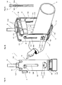
- FIG. 6a and 6b show the clamp 1 of FIG. 3 with the mounted on the ground or on an object mounting part 12, in which the receiving part 11 is suspended in such a way that the receiving segment 111 faces the mounting part 12.
- the tube 6 is inserted, which is fixed to the headband 2.
- the headband 2 is connected by means of the retaining screws 81 with the side pieces 110 of the receiving part 11.
- the retaining screws 81 are guided only in the slot openings 1101 of the side pieces 110, the overhang the mounting part 12.
- the connecting elements 1121, 1122 are in the same manner, but rotated by 180 ° in the first openings 126 of the side walls 121, 123 held.
- FIG. 7a, 7b, 7c and 7c show the mounting part 12 and the bracket 2 of the pipe clamp 1 of FIG. 3 from different perspectives
- FIGS. 8a and 8b show the receiving part 11 of the pipe clamp 1 of FIG. 3 from different perspectives.
- FIG. 8c shows the already described connecting elements 126, 1121, 1122, by means of which the mounting part 12 and the receiving part 11 are screwless and positively connected with each other, in a detailed view from the side.
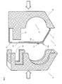
- FIG. 9 shows the mounting member 12 and the inserted receiving part 11 with a two insulation shells 5a, 5b existing fire protection insulation.
- the mutually complementary insulation shells 5a, 5b which are made, for example, of a fiber composite material or a foamed plastic, such as polyethylene, polystyrene, neopor, polyurethane, are shaped such that they cover the metal structure of the pipe clamp 1.
- the free space above the installed line 6 is preferably used to couple the two insulation shells 5a, 5b, the corresponding coupling elements 51, 52 and a recess for receiving the line 6 with each other.
- the insulation shells 5a, 5b are held by the wing elements 120. Furthermore, further outwardly directed holding elements can be provided, which engage or cut into the material of the insulation shells 5a, 5b.
Landscapes
- Engineering & Computer Science (AREA)
- General Engineering & Computer Science (AREA)
- Mechanical Engineering (AREA)
- Architecture (AREA)
- Civil Engineering (AREA)
- Structural Engineering (AREA)
- Clamps And Clips (AREA)
- Supports For Pipes And Cables (AREA)
Priority Applications (1)
| Application Number | Priority Date | Filing Date | Title |
|---|---|---|---|
| EP10161787.6A EP2325539B1 (fr) | 2009-11-13 | 2010-05-03 | Collier multifonctions |
Applications Claiming Priority (2)
| Application Number | Priority Date | Filing Date | Title |
|---|---|---|---|
| EP09176003A EP2322830A1 (fr) | 2009-11-13 | 2009-11-13 | Collier multifonctions |
| EP10161787.6A EP2325539B1 (fr) | 2009-11-13 | 2010-05-03 | Collier multifonctions |
Publications (2)
| Publication Number | Publication Date |
|---|---|
| EP2325539A1 true EP2325539A1 (fr) | 2011-05-25 |
| EP2325539B1 EP2325539B1 (fr) | 2016-07-13 |
Family
ID=51417918
Family Applications (1)
| Application Number | Title | Priority Date | Filing Date |
|---|---|---|---|
| EP10161787.6A Not-in-force EP2325539B1 (fr) | 2009-11-13 | 2010-05-03 | Collier multifonctions |
Country Status (1)
| Country | Link |
|---|---|
| EP (1) | EP2325539B1 (fr) |
Cited By (10)
| Publication number | Priority date | Publication date | Assignee | Title |
|---|---|---|---|---|
| CN103363190A (zh) * | 2013-07-30 | 2013-10-23 | 中国人民解放军总后勤部油料研究所 | 管线拉力器 |
| DE102014001161A1 (de) * | 2014-01-31 | 2015-08-06 | Murrplastik Systemtechnik Gmbh | Haltevorrichtung für Langkörper, insbesondere für Kabel |
| CN106226082A (zh) * | 2016-07-12 | 2016-12-14 | 中国航空工业集团公司沈阳发动机设计研究所 | 一种可调节的对开式测试引线固定装置 |
| CN110036228A (zh) * | 2016-11-30 | 2019-07-19 | J·范瓦尔拉芬私人控股有限公司 | 管吊架 |
| GB2572656A (en) * | 2018-08-17 | 2019-10-09 | Midland Fixings Ltd | Metal fastening for cables |
| EP3702652A1 (fr) | 2019-02-27 | 2020-09-02 | Gerster, Gaby | Collier |
| CN112827106A (zh) * | 2021-01-29 | 2021-05-25 | 武汉凤安技术有限公司 | 一种消防喷淋管道的吊式固定装置 |
| EP3865749A1 (fr) | 2020-02-16 | 2021-08-18 | Zurecon AG | Collier de serrage |
| CN115929992A (zh) * | 2022-11-29 | 2023-04-07 | 青岛市地铁六号线有限公司 | 综合支吊架体系及其施工方法 |
| WO2024063908A1 (fr) * | 2022-09-22 | 2024-03-28 | Panduit Corp. | Système de gestion de câbles |
Citations (15)
| Publication number | Priority date | Publication date | Assignee | Title |
|---|---|---|---|---|
| DE1851413U (de) * | 1962-03-15 | 1962-05-10 | Hilti Montage Technik Ges M B | Rohrschelle. |
| US3051424A (en) | 1959-09-28 | 1962-08-28 | Duhamel Gerard | Pipe hanger |
| FR2214343A5 (fr) | 1973-01-15 | 1974-08-09 | Gaillard Et Cie | |
| FR2520945A1 (fr) * | 1982-01-29 | 1983-08-05 | Essilor Int | Dispositif de fixation de cable d'alimentation ou de sortie |
| CH644436A5 (en) | 1981-11-03 | 1984-07-31 | Marc Luisier | Device for positioning pipes in a concrete slab |
| EP0666443A1 (fr) * | 1994-02-08 | 1995-08-09 | CO.PRO.TEC. S.r.l. | Dispositif pour fixation de tubes à une structure de support |
| JPH07293754A (ja) * | 1994-04-19 | 1995-11-10 | Howa Sangyo:Kk | 配管支持金具用保温具 |
| US5848770A (en) * | 1997-02-27 | 1998-12-15 | Sigma-Aldrich Co. | Clevis hanger |
| WO2001004529A1 (fr) | 1999-07-09 | 2001-01-18 | Eilif Elvegaard | Dispositif de serrage pour serrer des tubes ou analogues |
| EP1530272A2 (fr) * | 2003-10-25 | 2005-05-11 | Zurecon Ag | Dispositif de montage pour dispositif de guidage de cable |
| FR2880211A1 (fr) | 2004-12-23 | 2006-06-30 | Valeo Electronique Sys Liaison | Dispositif de fixation de gaines annelees |
| EP1741965A1 (fr) | 2005-07-07 | 2007-01-10 | Zurecon Ag | Collier de serrage pour tuyaux |
| EP1808629A2 (fr) | 2005-12-15 | 2007-07-18 | MBM Elettronica S.r.L. | Dispositif de serre-câble avec une pièce de verrouillage encliquetable/dégageable |
| DE102006033800A1 (de) | 2006-07-19 | 2008-01-31 | Siemens Ag | Kabelbefestigungsvorrichtung und Kabel mit Kabelbefestigungsvorrichtung |
| EP2112413A1 (fr) | 2008-04-25 | 2009-10-28 | Zurecon AG | Collier de serrage pour tuyaux |
-
2010
- 2010-05-03 EP EP10161787.6A patent/EP2325539B1/fr not_active Not-in-force
Patent Citations (15)
| Publication number | Priority date | Publication date | Assignee | Title |
|---|---|---|---|---|
| US3051424A (en) | 1959-09-28 | 1962-08-28 | Duhamel Gerard | Pipe hanger |
| DE1851413U (de) * | 1962-03-15 | 1962-05-10 | Hilti Montage Technik Ges M B | Rohrschelle. |
| FR2214343A5 (fr) | 1973-01-15 | 1974-08-09 | Gaillard Et Cie | |
| CH644436A5 (en) | 1981-11-03 | 1984-07-31 | Marc Luisier | Device for positioning pipes in a concrete slab |
| FR2520945A1 (fr) * | 1982-01-29 | 1983-08-05 | Essilor Int | Dispositif de fixation de cable d'alimentation ou de sortie |
| EP0666443A1 (fr) * | 1994-02-08 | 1995-08-09 | CO.PRO.TEC. S.r.l. | Dispositif pour fixation de tubes à une structure de support |
| JPH07293754A (ja) * | 1994-04-19 | 1995-11-10 | Howa Sangyo:Kk | 配管支持金具用保温具 |
| US5848770A (en) * | 1997-02-27 | 1998-12-15 | Sigma-Aldrich Co. | Clevis hanger |
| WO2001004529A1 (fr) | 1999-07-09 | 2001-01-18 | Eilif Elvegaard | Dispositif de serrage pour serrer des tubes ou analogues |
| EP1530272A2 (fr) * | 2003-10-25 | 2005-05-11 | Zurecon Ag | Dispositif de montage pour dispositif de guidage de cable |
| FR2880211A1 (fr) | 2004-12-23 | 2006-06-30 | Valeo Electronique Sys Liaison | Dispositif de fixation de gaines annelees |
| EP1741965A1 (fr) | 2005-07-07 | 2007-01-10 | Zurecon Ag | Collier de serrage pour tuyaux |
| EP1808629A2 (fr) | 2005-12-15 | 2007-07-18 | MBM Elettronica S.r.L. | Dispositif de serre-câble avec une pièce de verrouillage encliquetable/dégageable |
| DE102006033800A1 (de) | 2006-07-19 | 2008-01-31 | Siemens Ag | Kabelbefestigungsvorrichtung und Kabel mit Kabelbefestigungsvorrichtung |
| EP2112413A1 (fr) | 2008-04-25 | 2009-10-28 | Zurecon AG | Collier de serrage pour tuyaux |
Non-Patent Citations (1)
| Title |
|---|
| PETER NAUSE,: "Brandverhalten von Befestigungssystemen in der Installationstechnik", MATERIALPRUFANSTALT FUR DAS BAUWESEN, BRAUNSCHWEIG |
Cited By (13)
| Publication number | Priority date | Publication date | Assignee | Title |
|---|---|---|---|---|
| CN103363190A (zh) * | 2013-07-30 | 2013-10-23 | 中国人民解放军总后勤部油料研究所 | 管线拉力器 |
| DE102014001161A1 (de) * | 2014-01-31 | 2015-08-06 | Murrplastik Systemtechnik Gmbh | Haltevorrichtung für Langkörper, insbesondere für Kabel |
| CN106226082A (zh) * | 2016-07-12 | 2016-12-14 | 中国航空工业集团公司沈阳发动机设计研究所 | 一种可调节的对开式测试引线固定装置 |
| CN106226082B (zh) * | 2016-07-12 | 2019-03-08 | 中国航空工业集团公司沈阳发动机设计研究所 | 一种可调节的对开式测试引线固定装置 |
| CN110036228B (zh) * | 2016-11-30 | 2021-09-17 | J·范瓦尔拉芬私人控股有限公司 | 管吊架 |
| CN110036228A (zh) * | 2016-11-30 | 2019-07-19 | J·范瓦尔拉芬私人控股有限公司 | 管吊架 |
| GB2572656A (en) * | 2018-08-17 | 2019-10-09 | Midland Fixings Ltd | Metal fastening for cables |
| GB2572656B (en) * | 2018-08-17 | 2021-04-21 | Midland Fixings Ltd | Metal fastening for cables |
| EP3702652A1 (fr) | 2019-02-27 | 2020-09-02 | Gerster, Gaby | Collier |
| EP3865749A1 (fr) | 2020-02-16 | 2021-08-18 | Zurecon AG | Collier de serrage |
| CN112827106A (zh) * | 2021-01-29 | 2021-05-25 | 武汉凤安技术有限公司 | 一种消防喷淋管道的吊式固定装置 |
| WO2024063908A1 (fr) * | 2022-09-22 | 2024-03-28 | Panduit Corp. | Système de gestion de câbles |
| CN115929992A (zh) * | 2022-11-29 | 2023-04-07 | 青岛市地铁六号线有限公司 | 综合支吊架体系及其施工方法 |
Also Published As
| Publication number | Publication date |
|---|---|
| EP2325539B1 (fr) | 2016-07-13 |
Similar Documents
| Publication | Publication Date | Title |
|---|---|---|
| EP2325539B1 (fr) | Collier multifonctions | |
| DE60021469T2 (de) | Aufhängestange und Befestigungsklammeranordnung | |
| EP2313662B1 (fr) | Lien de fixation | |
| EP1833133B1 (fr) | Dispositif de montage pour un caniveau de câbles et caniveau de câbles | |
| EP2093524A1 (fr) | Dispositif destiné au montage de modules solaires | |
| EP2112413A1 (fr) | Collier de serrage pour tuyaux | |
| DE102005046766B3 (de) | Leitungshalterung in einem Flugzeug | |
| DE102009019337B4 (de) | Modulare Haltevorrichtung für innerhalb eines Flugzeugrumpfs verlegte Anbauteile | |
| EP3787137A1 (fr) | Dispositif de raccordement, garniture de raccordement et chemin de câbles | |
| EP4130409A1 (fr) | Système de fixation pour éléments de revêtement | |
| DE102008009703A1 (de) | Haltevorrichtung für plattenförmige Elemente | |
| CH669438A5 (en) | Clip and anchoring part | |
| DE202016104509U1 (de) | Ausleger | |
| DE3936003C2 (fr) | ||
| DE10352084B4 (de) | Befestigungselement und Verfahren zur Festlegung von Leitungen | |
| EP2403084A2 (fr) | Guidage de câble et de conduite | |
| DE3803335C2 (de) | Aufhängevorrichtung zum Befestigen einer Kabelmuffe am Tragseil eines Luftkabels | |
| CH684448A5 (de) | Montageschiene für Installationen in Gebäuden. | |
| DE4308566A1 (de) | Wandinstallationskanal | |
| DE102013105047B4 (de) | Anordnung zum Befestigen einer Schiene | |
| DE102008064940B3 (de) | Verbindungsanordnung für auf einem Sockel positionierte schrankförmige, vorgefertigte modulartige Aufsatzteile | |
| EP1420211B1 (fr) | Dispositif de support mural d'un radiateur | |
| DE202010003259U1 (de) | Befestigungssystem zur Halterung von Kabeln und Schläuchen an einem Träger | |
| CH697796B1 (de) | Verfahren zur Montage bzw. zum Einbringen eines Hohlkörpers in eine Betonwand oder Betondecke. | |
| DE19711316B4 (de) | Tragsystem für Kabel sowie Hängelager und Kabelrinne für ein solches Tragsystem |
Legal Events
| Date | Code | Title | Description |
|---|---|---|---|
| PUAI | Public reference made under article 153(3) epc to a published international application that has entered the european phase |
Free format text: ORIGINAL CODE: 0009012 |
|
| AK | Designated contracting states |
Kind code of ref document: A1 Designated state(s): AL AT BE BG CH CY CZ DE DK EE ES FI FR GB GR HR HU IE IS IT LI LT LU LV MC MK MT NL NO PL PT RO SE SI SK SM TR |
|
| AX | Request for extension of the european patent |
Extension state: BA ME RS |
|
| 17P | Request for examination filed |
Effective date: 20111125 |
|
| GRAP | Despatch of communication of intention to grant a patent |
Free format text: ORIGINAL CODE: EPIDOSNIGR1 |
|
| RIC1 | Information provided on ipc code assigned before grant |
Ipc: F16L 55/035 20060101ALI20140904BHEP Ipc: F16L 59/135 20060101AFI20140904BHEP Ipc: H02G 3/32 20060101ALI20140904BHEP Ipc: F16L 3/11 20060101ALI20140904BHEP Ipc: F16L 3/10 20060101ALI20140904BHEP Ipc: F16L 3/24 20060101ALI20140904BHEP |
|
| INTG | Intention to grant announced |
Effective date: 20141008 |
|
| 17Q | First examination report despatched |
Effective date: 20150206 |
|
| INTG | Intention to grant announced |
Effective date: 20151222 |
|
| GRAS | Grant fee paid |
Free format text: ORIGINAL CODE: EPIDOSNIGR3 |
|
| GRAA | (expected) grant |
Free format text: ORIGINAL CODE: 0009210 |
|
| AK | Designated contracting states |
Kind code of ref document: B1 Designated state(s): AL AT BE BG CH CY CZ DE DK EE ES FI FR GB GR HR HU IE IS IT LI LT LU LV MC MK MT NL NO PL PT RO SE SI SK SM TR |
|
| REG | Reference to a national code |
Ref country code: GB Ref legal event code: FG4D Free format text: NOT ENGLISH |
|
| REG | Reference to a national code |
Ref country code: AT Ref legal event code: REF Ref document number: 812634 Country of ref document: AT Kind code of ref document: T Effective date: 20160715 Ref country code: CH Ref legal event code: EP |
|
| REG | Reference to a national code |
Ref country code: CH Ref legal event code: NV Representative=s name: PETER RUTZ, CH |
|
| REG | Reference to a national code |
Ref country code: IE Ref legal event code: FG4D Free format text: LANGUAGE OF EP DOCUMENT: GERMAN |
|
| REG | Reference to a national code |
Ref country code: DE Ref legal event code: R096 Ref document number: 502010011989 Country of ref document: DE |
|
| REG | Reference to a national code |
Ref country code: LT Ref legal event code: MG4D |
|
| REG | Reference to a national code |
Ref country code: NL Ref legal event code: MP Effective date: 20160713 |
|
| PG25 | Lapsed in a contracting state [announced via postgrant information from national office to epo] |
Ref country code: NO Free format text: LAPSE BECAUSE OF FAILURE TO SUBMIT A TRANSLATION OF THE DESCRIPTION OR TO PAY THE FEE WITHIN THE PRESCRIBED TIME-LIMIT Effective date: 20161013 Ref country code: HR Free format text: LAPSE BECAUSE OF FAILURE TO SUBMIT A TRANSLATION OF THE DESCRIPTION OR TO PAY THE FEE WITHIN THE PRESCRIBED TIME-LIMIT Effective date: 20160713 Ref country code: LT Free format text: LAPSE BECAUSE OF FAILURE TO SUBMIT A TRANSLATION OF THE DESCRIPTION OR TO PAY THE FEE WITHIN THE PRESCRIBED TIME-LIMIT Effective date: 20160713 Ref country code: FI Free format text: LAPSE BECAUSE OF FAILURE TO SUBMIT A TRANSLATION OF THE DESCRIPTION OR TO PAY THE FEE WITHIN THE PRESCRIBED TIME-LIMIT Effective date: 20160713 Ref country code: IS Free format text: LAPSE BECAUSE OF FAILURE TO SUBMIT A TRANSLATION OF THE DESCRIPTION OR TO PAY THE FEE WITHIN THE PRESCRIBED TIME-LIMIT Effective date: 20161113 Ref country code: IT Free format text: LAPSE BECAUSE OF FAILURE TO SUBMIT A TRANSLATION OF THE DESCRIPTION OR TO PAY THE FEE WITHIN THE PRESCRIBED TIME-LIMIT Effective date: 20160713 Ref country code: NL Free format text: LAPSE BECAUSE OF FAILURE TO SUBMIT A TRANSLATION OF THE DESCRIPTION OR TO PAY THE FEE WITHIN THE PRESCRIBED TIME-LIMIT Effective date: 20160713 |
|
| PG25 | Lapsed in a contracting state [announced via postgrant information from national office to epo] |
Ref country code: PL Free format text: LAPSE BECAUSE OF FAILURE TO SUBMIT A TRANSLATION OF THE DESCRIPTION OR TO PAY THE FEE WITHIN THE PRESCRIBED TIME-LIMIT Effective date: 20160713 Ref country code: LV Free format text: LAPSE BECAUSE OF FAILURE TO SUBMIT A TRANSLATION OF THE DESCRIPTION OR TO PAY THE FEE WITHIN THE PRESCRIBED TIME-LIMIT Effective date: 20160713 Ref country code: PT Free format text: LAPSE BECAUSE OF FAILURE TO SUBMIT A TRANSLATION OF THE DESCRIPTION OR TO PAY THE FEE WITHIN THE PRESCRIBED TIME-LIMIT Effective date: 20161114 Ref country code: ES Free format text: LAPSE BECAUSE OF FAILURE TO SUBMIT A TRANSLATION OF THE DESCRIPTION OR TO PAY THE FEE WITHIN THE PRESCRIBED TIME-LIMIT Effective date: 20160713 Ref country code: SE Free format text: LAPSE BECAUSE OF FAILURE TO SUBMIT A TRANSLATION OF THE DESCRIPTION OR TO PAY THE FEE WITHIN THE PRESCRIBED TIME-LIMIT Effective date: 20160713 Ref country code: GR Free format text: LAPSE BECAUSE OF FAILURE TO SUBMIT A TRANSLATION OF THE DESCRIPTION OR TO PAY THE FEE WITHIN THE PRESCRIBED TIME-LIMIT Effective date: 20161014 |
|
| REG | Reference to a national code |
Ref country code: DE Ref legal event code: R097 Ref document number: 502010011989 Country of ref document: DE |
|
| PG25 | Lapsed in a contracting state [announced via postgrant information from national office to epo] |
Ref country code: RO Free format text: LAPSE BECAUSE OF FAILURE TO SUBMIT A TRANSLATION OF THE DESCRIPTION OR TO PAY THE FEE WITHIN THE PRESCRIBED TIME-LIMIT Effective date: 20160713 Ref country code: EE Free format text: LAPSE BECAUSE OF FAILURE TO SUBMIT A TRANSLATION OF THE DESCRIPTION OR TO PAY THE FEE WITHIN THE PRESCRIBED TIME-LIMIT Effective date: 20160713 |
|
| PLBE | No opposition filed within time limit |
Free format text: ORIGINAL CODE: 0009261 |
|
| STAA | Information on the status of an ep patent application or granted ep patent |
Free format text: STATUS: NO OPPOSITION FILED WITHIN TIME LIMIT |
|
| PG25 | Lapsed in a contracting state [announced via postgrant information from national office to epo] |
Ref country code: SM Free format text: LAPSE BECAUSE OF FAILURE TO SUBMIT A TRANSLATION OF THE DESCRIPTION OR TO PAY THE FEE WITHIN THE PRESCRIBED TIME-LIMIT Effective date: 20160713 Ref country code: BG Free format text: LAPSE BECAUSE OF FAILURE TO SUBMIT A TRANSLATION OF THE DESCRIPTION OR TO PAY THE FEE WITHIN THE PRESCRIBED TIME-LIMIT Effective date: 20161013 Ref country code: CZ Free format text: LAPSE BECAUSE OF FAILURE TO SUBMIT A TRANSLATION OF THE DESCRIPTION OR TO PAY THE FEE WITHIN THE PRESCRIBED TIME-LIMIT Effective date: 20160713 Ref country code: DK Free format text: LAPSE BECAUSE OF FAILURE TO SUBMIT A TRANSLATION OF THE DESCRIPTION OR TO PAY THE FEE WITHIN THE PRESCRIBED TIME-LIMIT Effective date: 20160713 Ref country code: SK Free format text: LAPSE BECAUSE OF FAILURE TO SUBMIT A TRANSLATION OF THE DESCRIPTION OR TO PAY THE FEE WITHIN THE PRESCRIBED TIME-LIMIT Effective date: 20160713 |
|
| REG | Reference to a national code |
Ref country code: FR Ref legal event code: PLFP Year of fee payment: 8 |
|
| 26N | No opposition filed |
Effective date: 20170418 |
|
| PG25 | Lapsed in a contracting state [announced via postgrant information from national office to epo] |
Ref country code: LU Free format text: LAPSE BECAUSE OF NON-PAYMENT OF DUE FEES Effective date: 20170531 Ref country code: SI Free format text: LAPSE BECAUSE OF FAILURE TO SUBMIT A TRANSLATION OF THE DESCRIPTION OR TO PAY THE FEE WITHIN THE PRESCRIBED TIME-LIMIT Effective date: 20160713 |
|
| GBPC | Gb: european patent ceased through non-payment of renewal fee |
Effective date: 20170503 |
|
| PG25 | Lapsed in a contracting state [announced via postgrant information from national office to epo] |
Ref country code: MC Free format text: LAPSE BECAUSE OF FAILURE TO SUBMIT A TRANSLATION OF THE DESCRIPTION OR TO PAY THE FEE WITHIN THE PRESCRIBED TIME-LIMIT Effective date: 20160713 |
|
| REG | Reference to a national code |
Ref country code: IE Ref legal event code: MM4A |
|
| PG25 | Lapsed in a contracting state [announced via postgrant information from national office to epo] |
Ref country code: LU Free format text: LAPSE BECAUSE OF NON-PAYMENT OF DUE FEES Effective date: 20170503 |
|
| REG | Reference to a national code |
Ref country code: BE Ref legal event code: MM Effective date: 20170531 |
|
| PG25 | Lapsed in a contracting state [announced via postgrant information from national office to epo] |
Ref country code: GB Free format text: LAPSE BECAUSE OF NON-PAYMENT OF DUE FEES Effective date: 20170503 Ref country code: IE Free format text: LAPSE BECAUSE OF NON-PAYMENT OF DUE FEES Effective date: 20170503 |
|
| REG | Reference to a national code |
Ref country code: AT Ref legal event code: MM01 Ref document number: 812634 Country of ref document: AT Kind code of ref document: T Effective date: 20170503 |
|
| PGFP | Annual fee paid to national office [announced via postgrant information from national office to epo] |
Ref country code: CH Payment date: 20180523 Year of fee payment: 9 Ref country code: DE Payment date: 20180522 Year of fee payment: 9 |
|
| PG25 | Lapsed in a contracting state [announced via postgrant information from national office to epo] |
Ref country code: BE Free format text: LAPSE BECAUSE OF NON-PAYMENT OF DUE FEES Effective date: 20170531 Ref country code: AT Free format text: LAPSE BECAUSE OF NON-PAYMENT OF DUE FEES Effective date: 20170503 |
|
| REG | Reference to a national code |
Ref country code: CH Ref legal event code: PCAR Free format text: NEW ADDRESS: ALPENSTRASSE 14 POSTFACH 7627, 6302 ZUG (CH) |
|
| REG | Reference to a national code |
Ref country code: FR Ref legal event code: PLFP Year of fee payment: 9 |
|
| PG25 | Lapsed in a contracting state [announced via postgrant information from national office to epo] |
Ref country code: MT Free format text: LAPSE BECAUSE OF FAILURE TO SUBMIT A TRANSLATION OF THE DESCRIPTION OR TO PAY THE FEE WITHIN THE PRESCRIBED TIME-LIMIT Effective date: 20160713 |
|
| PG25 | Lapsed in a contracting state [announced via postgrant information from national office to epo] |
Ref country code: AL Free format text: LAPSE BECAUSE OF FAILURE TO SUBMIT A TRANSLATION OF THE DESCRIPTION OR TO PAY THE FEE WITHIN THE PRESCRIBED TIME-LIMIT Effective date: 20160713 |
|
| PGFP | Annual fee paid to national office [announced via postgrant information from national office to epo] |
Ref country code: FR Payment date: 20180911 Year of fee payment: 9 |
|
| PG25 | Lapsed in a contracting state [announced via postgrant information from national office to epo] |
Ref country code: HU Free format text: LAPSE BECAUSE OF FAILURE TO SUBMIT A TRANSLATION OF THE DESCRIPTION OR TO PAY THE FEE WITHIN THE PRESCRIBED TIME-LIMIT; INVALID AB INITIO Effective date: 20100503 |
|
| PG25 | Lapsed in a contracting state [announced via postgrant information from national office to epo] |
Ref country code: CY Free format text: LAPSE BECAUSE OF NON-PAYMENT OF DUE FEES Effective date: 20160713 |
|
| PG25 | Lapsed in a contracting state [announced via postgrant information from national office to epo] |
Ref country code: MK Free format text: LAPSE BECAUSE OF FAILURE TO SUBMIT A TRANSLATION OF THE DESCRIPTION OR TO PAY THE FEE WITHIN THE PRESCRIBED TIME-LIMIT Effective date: 20160713 |
|
| REG | Reference to a national code |
Ref country code: DE Ref legal event code: R119 Ref document number: 502010011989 Country of ref document: DE |
|
| REG | Reference to a national code |
Ref country code: CH Ref legal event code: PL |
|
| PG25 | Lapsed in a contracting state [announced via postgrant information from national office to epo] |
Ref country code: LI Free format text: LAPSE BECAUSE OF NON-PAYMENT OF DUE FEES Effective date: 20190531 Ref country code: CH Free format text: LAPSE BECAUSE OF NON-PAYMENT OF DUE FEES Effective date: 20190531 |
|
| PG25 | Lapsed in a contracting state [announced via postgrant information from national office to epo] |
Ref country code: TR Free format text: LAPSE BECAUSE OF FAILURE TO SUBMIT A TRANSLATION OF THE DESCRIPTION OR TO PAY THE FEE WITHIN THE PRESCRIBED TIME-LIMIT Effective date: 20160713 |
|
| PG25 | Lapsed in a contracting state [announced via postgrant information from national office to epo] |
Ref country code: DE Free format text: LAPSE BECAUSE OF NON-PAYMENT OF DUE FEES Effective date: 20191203 |
|
| PG25 | Lapsed in a contracting state [announced via postgrant information from national office to epo] |
Ref country code: FR Free format text: LAPSE BECAUSE OF NON-PAYMENT OF DUE FEES Effective date: 20190531 |