EP2325593B1 - Échangeur de chaleur - Google Patents
Échangeur de chaleur Download PDFInfo
- Publication number
- EP2325593B1 EP2325593B1 EP09290872.2A EP09290872A EP2325593B1 EP 2325593 B1 EP2325593 B1 EP 2325593B1 EP 09290872 A EP09290872 A EP 09290872A EP 2325593 B1 EP2325593 B1 EP 2325593B1
- Authority
- EP
- European Patent Office
- Prior art keywords
- opening
- connection
- fluid
- heat exchanger
- arrangement
- Prior art date
- Legal status (The legal status is an assumption and is not a legal conclusion. Google has not performed a legal analysis and makes no representation as to the accuracy of the status listed.)
- Active
Links
Images
Classifications
-
- F—MECHANICAL ENGINEERING; LIGHTING; HEATING; WEAPONS; BLASTING
- F28—HEAT EXCHANGE IN GENERAL
- F28F—DETAILS OF HEAT-EXCHANGE AND HEAT-TRANSFER APPARATUS, OF GENERAL APPLICATION
- F28F9/00—Casings; Header boxes; Auxiliary supports for elements; Auxiliary members within casings
- F28F9/02—Header boxes; End plates
- F28F9/0246—Arrangements for connecting header boxes with flow lines
- F28F9/0248—Arrangements for sealing connectors to header boxes
-
- F—MECHANICAL ENGINEERING; LIGHTING; HEATING; WEAPONS; BLASTING
- F28—HEAT EXCHANGE IN GENERAL
- F28D—HEAT-EXCHANGE APPARATUS, NOT PROVIDED FOR IN ANOTHER SUBCLASS, IN WHICH THE HEAT-EXCHANGE MEDIA DO NOT COME INTO DIRECT CONTACT
- F28D1/00—Heat-exchange apparatus having stationary conduit assemblies for one heat-exchange medium only, the media being in contact with different sides of the conduit wall, in which the other heat-exchange medium is a large body of fluid, e.g. domestic or motor car radiators
- F28D1/02—Heat-exchange apparatus having stationary conduit assemblies for one heat-exchange medium only, the media being in contact with different sides of the conduit wall, in which the other heat-exchange medium is a large body of fluid, e.g. domestic or motor car radiators with heat-exchange conduits immersed in the body of fluid
- F28D1/04—Heat-exchange apparatus having stationary conduit assemblies for one heat-exchange medium only, the media being in contact with different sides of the conduit wall, in which the other heat-exchange medium is a large body of fluid, e.g. domestic or motor car radiators with heat-exchange conduits immersed in the body of fluid with tubular conduits
- F28D1/053—Heat-exchange apparatus having stationary conduit assemblies for one heat-exchange medium only, the media being in contact with different sides of the conduit wall, in which the other heat-exchange medium is a large body of fluid, e.g. domestic or motor car radiators with heat-exchange conduits immersed in the body of fluid with tubular conduits the conduits being straight
- F28D1/0535—Heat-exchange apparatus having stationary conduit assemblies for one heat-exchange medium only, the media being in contact with different sides of the conduit wall, in which the other heat-exchange medium is a large body of fluid, e.g. domestic or motor car radiators with heat-exchange conduits immersed in the body of fluid with tubular conduits the conduits being straight the conduits having a non-circular cross-section
- F28D1/05366—Assemblies of conduits connected to common headers, e.g. core type radiators
-
- F—MECHANICAL ENGINEERING; LIGHTING; HEATING; WEAPONS; BLASTING
- F28—HEAT EXCHANGE IN GENERAL
- F28F—DETAILS OF HEAT-EXCHANGE AND HEAT-TRANSFER APPARATUS, OF GENERAL APPLICATION
- F28F9/00—Casings; Header boxes; Auxiliary supports for elements; Auxiliary members within casings
- F28F9/02—Header boxes; End plates
- F28F9/0246—Arrangements for connecting header boxes with flow lines
Definitions
- the invention relates to a heat exchanger according to the preamble of claim 1, a method for producing a heat exchanger according to the preamble of claim 6 and an automotive air conditioning system.
- a heat exchanger is out US 5,363,910 known.
- Heat exchangers are used for various technical applications for cooling and / or for heating fluids.
- a fluid to be cooled or heated to be heated by the heat exchanger and by means of a heat transfer fluid flowing around the fluid in the heat exchanger can be cooled or heated.
- Heat exchangers generally have a multiplicity of tubes, which are mechanically and hydraulically connected to two manifolds at the ends of the tubes. This creates a hydraulic connection between the two headers and the pipes. Between the tubes, which are designed in particular as flat tubes, are generally corrugated fins. At the manifold is an inlet port and an outlet port for introducing and discharging the fluid to be cooled or heated arranged.
- a connection device for connecting a line to a connection opening and a fastening device for the line or a device arranged on the line is located at the inlet opening and at the outlet opening.
- the incoming or outgoing fluid is thus first passed from the line through the connection device and then from the connection device into the inlet or outlet opening on the collection tube.
- Heat exchangers can also be used as refrigerant condensers in motor vehicle air conditioners and are used for cooling and liquefying a fluid to be cooled, namely refrigerant, which is passed through the refrigerant condenser.
- connection devices for the heat exchanger are produced by cutting off the individual connection devices from a solid profile or rod produced by means of extrusion. In these cut parts is then machined, for example by drilling or milling, a connection opening and a fluid opening incorporated. Furthermore, a mounting hole is incorporated and, for example, a screw is screwed into the mounting hole after incorporating a thread. By means of the screw as a fastening device, a line or a device can be attached to the line to the connection device. At the collecting pipe, a passage is formed at the inlet and outlet openings and the passage is inserted into the fluid opening of the connection device and then soldered. The connection device is thus complicated to manufacture and expensive.
- connection device Due to the use of a full profile produced by means of extrusion in the production of the connection device, the connection device has a high material requirement and due to the high cost of this material, it is generally aluminum, high cost therefore arise alone. Furthermore, many manufacturing steps are required for the machining of the connection device required, so that this also incurs high costs in the production of the connection device disadvantageously.
- the object of the present invention is therefore to provide a heat exchanger, a method for producing a heat exchanger and a motor vehicle air conditioning system, in which a connection device has a low material requirement and the production of the connection device is simple and inexpensive with only a few production steps.
- connection device thus advantageously comprises a connection pipe socket which is not a solid profile according to the design of the connection device in the prior art. As a result, material can be saved during production for the connection device.
- connection device comprises a connection plate with a connection opening and the connection pipe connection piece is connected to the connection plate at the connection opening and / or one end of the connection connection piece forms the connection opening.
- connection plate serves to connect the line to the connection device, so that there is a large contact surface for a device on the tube, without requiring a high material requirement because the connection plate is merely a plate with a small material thickness and not a solid profile.
- the thickness of at least one wall of the connection pipe socket and / or the connection plate is less than 2 cm, 1 cm, 0.5 cm or 0.3 cm. Due to the thickness of the at least one wall thus little material is required for the connection device.
- the at least one connection device preferably consists at least partially, in particular completely of metal, for example aluminum or steel.
- connection plate is substantially perpendicular to an axis of the connection pipe socket and / or the connection plate is provided with a mounting opening, in particular mounting hole, and in the mounting opening, the fastening device, for.
- the axis of the connection pipe socket is at a deviation of less than 30 °, 20 ° or 10 ° perpendicular to the connection plate, ie a plane of the connection plate.
- the plane of the connection plate is a plane which is aligned parallel to the largest extension of the connection plate and / or is aligned parallel to the largest planar partial surface of the connection plate.
- the heat exchanger comprises a collecting container with a dryer and / or a filter and / or the connection pipe socket is provided with a fluid opening.
- the heat exchanger comprises the collecting container with the dryer and / or the filter.
- the collecting pipe has a passage and in the fluid opening of the connecting pipe connection, the passage is arranged, so that thereby a mechanical connection between the boundary of the fluid opening at the connection pipe socket and the passage to the collecting pipe consists.
- a method according to the invention for producing a heat exchanger, heat exchanger described in this patent application, for cooling or heating a fluid to be passed through the heat exchanger, in particular a refrigerant condenser for an automotive air conditioning system comprising the steps of: providing tubes, providing at least one collecting tube with openings, Arranging the tubes in the openings of the at least one collecting tube, producing at least one connecting device for connecting a line for the fluid with a connection opening and preferably a fastening device for the line, connecting the tubes, the at least one collecting tube and preferably the at least one connecting device, in particular by means of brazing in a brazing furnace, so that they are mechanically connected to one another and a fluid-conducting connection between the tubes, the at least one collecting tube and the at least one connecting device, wherein the at least one connecting device with pressure forming, for example with extrusion, especially reverse extrusion, and / or deep drawing, from at least one workpiece blank is made in one piece.
- connection device Due to the production of the at least one connection device with extruding, in particular backward extrusion and / or deep drawing, a connection device can be produced from a workpiece blank in a simple manner, which has low wall thicknesses and thus there is a low material requirement in the production of the at least one connection device.
- the at least one connection device can be produced inexpensively with a low material requirement, for example aluminum.
- connection pipe socket with extrusions in particular with backward extrusion presses, is produced from one, preferably only one, workpiece blank, and a fluid opening, in particular a fluid bore, is worked into the connection pipe socket.
- a connection pipe socket is first produced from a first workpiece blank by means of backward extrusion.
- the connection pipe socket preferably has two sections with a different diameter.
- connection pipe stub made by means of backward extrusion, which is open at one end and has a connection opening and has no opening at the other end, ie is closed, is in the area or in the vicinity of the end without the opening perpendicular to an axis of the connection pipe socket, ie radially, incorporated a fluid opening.
- the fluid opening is preferably machined, for example by means of drilling or milling, incorporated into the connection pipe socket produced by means of backward extrusion.
- connection plate with a connection opening and a fastening opening is provided, preferably the connection plate is produced with punching from a raw plate, and the connection pipe connection piece is fastened in the connection opening of the connection plate.
- the connecting plates are punched out of the metal blank plate from a metal blank plate produced, for example, by means of rolling, so that the connecting plate can be produced or made available in a simple manner with a low manufacturing outlay.
- the connection opening and the attachment opening is stamped into this punched-out connection plate during punching or after punching out the outlet opening and / or the attachment opening is machined, for example by means of drilling or milling, into the stamped connection plate.
- connection pipe socket produced by extrusion is attached to the connection opening of the connection plate. This is performed for example cohesively and / or non-positively and / or positively.
- the connection pipe socket can be fixed for example by means of a press fit in the connection opening of the connection plate.
- soldering the connection pipe socket can be attached to the connection plate.
- a collecting container is provided and the collecting container, the tubes, the at least one collecting tube and the at least one connecting device are connected to one another so that they are mechanically connected to one another and a fluid-conducting connection between the collecting container, the tubes, the at least a manifold and the at least one connection device consists.
- a heat exchanger as a refrigerant condenser and a collection container is required.
- a dryer and / or a filter is preferably arranged.
- the at least one connection device with a connection pipe socket and a connection plate is produced from a workpiece blank with deep drawing.
- the connection device with the connection pipe socket and the connection plate can thus also be produced from only one workpiece blank by means of deep drawing.
- the connection device already has the connection pipe socket and the connection plate and these are already connected to one another due to the production of only one workpiece blank.
- the fluid opening is incorporated, for example by machining, in particular by means of drilling and / or milling.
- a fastening opening in particular fastening bore, is incorporated in the connecting plate and in the fastening opening is a fastening device, for.
- a fastening device for.
- a fastening device such as a screw or bolt
- a fastening device attached, preferably screwed by previously been incorporated into the mounting hole a thread or when screwing the screw into the mounting hole, the thread on the terminal plate automatically from the thread of the screw is produced.
- a line can be attached to the connection device.
- the line at the end of a corresponding device and on this device a corresponding counter-fastening device is arranged, by means of which the device can be attached to the line to the fastening device.
- the counter-fastening device is in this case to a corresponding thread into which the screw is screwed to the connection plate can be.
- the line is thereby fluidly connected to the connection opening of the connection device.
- an inlet opening and / or an outlet opening is incorporated in the at least one collecting tube and / or in the collecting container, a passage is preferably incorporated at the inlet opening and / or the outlet opening, and the at least one connection device, in particular the fluid opening of the connecting pipe connection , is connected to the at least one collecting tube and / or the collecting container at the inlet opening and / or the outlet opening, in particular soldered in a soldering oven and / or grained.
- the passage at the inlet opening and / or the outlet opening is inserted into the fluid opening of the connection pipe socket.
- An automotive air conditioning system comprises a heat exchanger described in this patent application.
- the motor vehicle air conditioning system comprises a refrigerant evaporator and / or a refrigerant condenser and / or a compressor and / or a control unit and / or a blower.
- the refrigerant condenser and / or the refrigerant evaporator are designed as a heat exchanger described in this patent application.
- corrugated fins are arranged on the heat exchanger between the tubes.
- the corrugated fins on the tubes are materially connected, in particular by means of soldering.
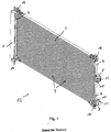
- Fig. 1 is a view of a known from the prior art heat exchanger 1 is shown. Between two headers 4, a plurality of tubes 3 are arranged. Between the tubes 3, corrugated fins, not shown, are formed of aluminum, which connect the tubes 3 both mechanically and thermally. The corrugated fins serve to increase the surface of the heat exchanger 1 and thereby increase the heat transfer.
- a connection device 8 On the right hand manifold 4 is an in Fig. 1 not shown inlet opening 6 and an outlet opening 7, not shown, which are each surrounded by a connection device 8 or closed. By means of the connection device 8, a line (not shown) is connected to the heat exchanger 1.
- the heat exchanger 1 serves as a refrigerant condenser 2 in an automotive air conditioning system.
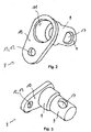
- the heat exchanger 1 according to the invention as a refrigerant condenser 2 substantially corresponds to the in Fig. 1 Only the connection devices 8 of the heat exchanger 1 have a different structure and are in the Fig. 2 to 4 displayed.
- the connection device 8 has a connection pipe socket 9 and a connection plate 10.
- the connection pipe socket 9 is produced by means of reverse extrusion from a first workpiece blank and has two sections with a different diameter.
- the connection pipe socket 9 points at one, in Fig. 2 shown above a connection opening 11 and a second end of the connecting pipe socket 9 has no opening, ie is closed. In the region of the end of the connection pipe socket 9 without opening, a fluid opening 17 is formed on a wall.
- connection plate 10 has the connection opening 11 and a fastening opening 12 designed as a fastening bore 13.
- the connection pipe socket 9 is fastened in the region of its connection opening 11 to the connection opening 11 of the connection plate 10 by means of a press fit and preferably additionally by means of soldering.
- the connection plate 10 is produced by punching from a raw plate and the connection opening 11 and the mounting hole 13 are already made during punching out of the raw plate, so that thereby a low production cost for the connection plate 10 is obtained.
- connection plate 10 and the connecting pipe socket 9 have a small thickness, for. B. of 0.3 mm or 0.2 mm.
- a low material requirement is required in the production of the connection device 8.
- connection pipe socket 9 and the connection plate 10 is generally used aluminum.
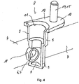
- connection device 8 is fastened with the fluid opening 17 on a passage 18 of the collecting pipe 4 ( Fig. 4 ).
- the tubes 3, as well as the not shown interposed corrugated fins and the manifold 4 and the reservoir 5 of the heat exchanger 1 are plated on the surface with solder.
- an inlet opening 6 and an outlet opening 7 are each incorporated with passages 18 at a collecting pipe 4.
- connection device 8 is fastened to the fluid opening 17.
- the fluid opening 17 is attached to the passage 18 by means of graining.
- the heat exchanger 1 comprising the tubes 3, the corrugated fins, the two manifolds 4, the collecting container 5 and the two connection devices 8 are introduced into a soldering oven for soldering. Due to the plating of the components of the heat exchanger 1 in particular also of the manifold 4 with the passage 18, the connection device 8 is soldered to the fluid opening 17 with the passage 18 of the manifold 4 by means of soldering. This is a fluid-tight Connection between the connection device 8 and the collecting pipe 4.
- connection opening 11 on the connection device 8 can be introduced or discharged through the connection opening 11 on the connection device 8, which then flows in or out through the connection pipe connection 9 and subsequently the connection pipe connection 9 at the fluid opening 17 leaves or flows back there and flows through the inlet or outlet port 6, 7 in the manifold 4 or flows out.
- connection plate 10 of the connection device 8 On the connection plate 10 of the connection device 8, a line, not shown, to be attached to the line in the refrigerant in the connection pipe socket 9 or divert.
- a fastening device 14 designed as a screw 15 is fastened to the fastening opening 12 by means of screws.
- the device on the line (not shown) in this case has a correspondingly formed counter-fastening device (not shown), for example a thread or a snap closure, so that thereby the device of the line, not shown, can be mechanically and also fluid-tightly fastened to the connection device 8.
- the screw 15 consists of iron, which is provided with a corrosion protection or a corrosion coating.
- the screw 15 is attached to the connector 8 only after brazing in the brazing furnace in which temperatures in the range of about 700 ° C are present. If, in the manufacture of the connection device 8, the screw 15 is already fastened to the connection plate 10 before soldering in the soldering oven, the screw 15 is to be made of stainless steel, because a screw made of iron with a corrosion coating does not meet the high temperatures in the soldering oven of about 700 ° C. withstand.
- connection device 8 namely the connection plate 10 and the connection pipe socket 9
- connection plate 10 and the connection pipe socket 9 are produced by extrusion and stamping and have a small wall thickness.
- a low material requirement for the connection plate 10 and the connection pipe socket 9 made of aluminum is required.
- the manufacturing costs can thus both be reduced because a low material requirement for the connection pipe socket 9 and the connection plate 10 is required and also little manufacturing steps are required.
Landscapes
- Engineering & Computer Science (AREA)
- Physics & Mathematics (AREA)
- Thermal Sciences (AREA)
- Mechanical Engineering (AREA)
- General Engineering & Computer Science (AREA)
- Air-Conditioning For Vehicles (AREA)
- Heat-Exchange Devices With Radiators And Conduit Assemblies (AREA)
Claims (14)
- Echangeur de chaleur (1) servant au refroidissement ou au chauffage d'un fluide devant traverser l'échangeur de chaleur (1), en particulier le condenseur de fluide frigorigène (2) prévu pour un système de climatisation d'un véhicule automobile, ledit échangeur de chaleur comprenant :- une multiplicité de tubes (3),- au moins un tube collecteur (4) ayant des ouvertures dans lesquelles les tubes (3) sont disposés, pour permettre un raccordement hydraulique entre les tubes (3) et le tube collecteur (4) au moins au nombre de un,- une ouverture d'entrée (6) servant à l'introduction d'un fluide,- une ouverture de sortie (7) servant à l'évacuation du fluide,- au moins un dispositif de raccordement (8) servant au raccordement d'une conduite pour le fluide, ledit dispositif de raccordement ayant une ouverture de raccordement (11) et, de préférence, un dispositif de fixation (14) pour la conduite,où le dispositif de raccordement (8) au moins au nombre de un est disposé au niveau de l'ouverture d'entrée (6) et / ou de l'ouverture de sortie (7),
où le dispositif de raccordement (8) au moins au nombre de un comprend une tubulure de raccordement (9), où la tubulure de raccordement (9) est dotée, dans sa surface de paroi de forme tubulaire, d'une ouverture de fluide (17), et un passage de forme tubulaire (18) est disposé, dans l'ouverture de fluide (17), au niveau de l'ouverture d'entrée (6) et / ou de l'ouverture de sortie (7) placée au niveau du tube collecteur (4) au moins au nombre de un et / ou au niveau du réservoir collecteur (5), où le dispositif de raccordement (8) est monobloc,
caractérisé en ce que le dispositif de raccordement (8) est fabriqué par formage. - Echangeur de chaleur selon la revendication 1, caractérisé en ce que le dispositif de raccordement (8) comprend une plaque de raccordement (10) ayant une ouverture de raccordement (11), et la tubulure de raccordement (9) est reliée, au niveau de l'ouverture de raccordement (11), à la plaque de raccordement (10), et / ou une extrémité de la tubulure de raccordement (9) forme l'ouverture de raccordement (11).
- Echangeur de chaleur selon la revendication 1 ou 2, caractérisé en ce que l'épaisseur au moins d'une paroi de la tubulure de raccordement (9) et / ou de la plaque de raccordement (10) est inférieure à 2 cm, à 1 cm, à 0,5 cm ou à 0,3 cm.
- Echangeur de chaleur selon la revendication 2 ou 3, caractérisé en ce que la plaque de raccordement (10) est pratiquement perpendiculaire à un axe de la tubulure de raccordement (9) et / ou la plaque de raccordement (10) est dotée d'une ouverture de fixation (12), en particulier d'un perçage (13) pour la fixation, et le dispositif de fixation (14), par exemple une vis (15) ou un boulon, est fixé dans l'ouverture de fixation (12), pour fixer la conduite sur le dispositif de raccordement (8).
- Echangeur de chaleur selon l'une quelconque ou plusieurs des revendications précédentes, caractérisé en ce que l'échangeur de chaleur (1) comprend un réservoir collecteur (5) comportant un déshydrateur et / ou un filtre.
- Procédé de fabrication d'un échangeur de chaleur (1) selon l'une quelconque ou plusieurs des revendications précédentes, ledit échangeur de chaleur servant au refroidissement ou au chauffage d'un fluide devant traverser l'échangeur de chaleur (1), en particulier le condenseur de fluide frigorigène (2) prévu pour un système de climatisation d'un véhicule automobile, ledit procédé comprenant les étapes consistant :- à fournir des tubes (3),- à fournir au moins un tube collecteur (4) ayant des ouvertures,- à agencer les tubes (3) dans les ouvertures du tube collecteur (4) au moins au nombre de un,- à fabriquer au moins un dispositif de raccordement (8) servant au raccordement d'une conduite pour le fluide, ledit dispositif de raccordement ayant une ouverture de raccordement (11) et, de préférence, un dispositif de fixation (14) pour la conduite,- à procéder à l'assemblage des tubes (3), du tube collecteur (4) au moins au nombre de un et, de préférence, du dispositif de raccordement (8) au moins au nombre de un, l'assemblage étant réalisé en particulier par brasage dans un four à braser, de sorte que ces éléments sont combinés mécaniquement les uns avec les autres, et il se produit une communication permettant au fluide de circuler entre les tubes (3), le tube collecteur (4) au moins au nombre de un et entre le dispositif de raccordement (8) au moins au nombre de un,caractérisé en ce que le dispositif de raccordement (8) au moins au nombre de un est fabriqué de façon monobloc, à partir au moins d'une ébauche de la pièce à usiner, la fabrication étant réalisée par formage sous pression, par exemple par extrusion, en particulier par extrusion en arrière et / ou par emboutissage profond.
- Procédé selon la revendication 6, caractérisé en ce qu'une tubulure de raccordement (9) est fabriquée à partir d'une ébauche de la pièce à usiner, la fabrication étant réalisée par extrusion, en particulier par extrusion en arrière, et une ouverture de fluide (17), en particulier un perçage pour le fluide, est usiné(e) dans la tubulure de raccordement (9).
- Procédé selon la revendication 7, caractérisé en ce qu'une plaque de raccordement (10) est fournie, ladite plaque ayant une ouverture de raccordement (11) et une ouverture de fixation (12), la plaque de raccordement (10) étant fabriquée, de préférence, par estampage à partir d'une plaque brute, et la tubulure de raccordement (9) est fixée dans l'ouverture de raccordement (11) de la plaque de raccordement (10).
- Procédé selon l'une quelconque ou plusieurs des revendications 6 à 8, caractérisé en ce qu'un réservoir collecteur (5) est fourni, et le réservoir collecteur (5), les tubes (3), le tube collecteur (4) au moins au nombre de un et le dispositif de raccordement (8) au moins au nombre de un sont assemblés les uns avec les autres, de sorte que ces éléments sont combinés mécaniquement les uns avec les autres, et il se produit une communication permettant au fluide de circuler entre le réservoir collecteur (5), les tubes (3), le tube collecteur (4) au moins au nombre de un et entre le dispositif de raccordement (8) au moins au nombre de un.
- Procédé selon la revendication 6 ou 9, caractérisé en ce que le dispositif de raccordement (8) au moins au nombre de un comportant une tubulure de raccordement (9) et une plaque de raccordement (10) est fabriqué par emboutissage profond, à partir d'une ébauche de la pièce à usiner.
- Procédé selon l'une quelconque ou plusieurs des revendications 6 à 10, caractérisé en ce qu'une ouverture de fixation (12), en particulier un perçage (13) pour la fixation, est usiné (e) dans la plaque de raccordement (10), et un dispositif de fixation (14), par exemple une vis (15) ou un boulon, est fixé dans l'ouverture de fixation (12).
- Procédé selon l'une quelconque ou plusieurs des revendications 6 à 11, caractérisé en ce qu'une ouverture d'entrée (6) et / ou une ouverture de sortie (7) est usinée dans le tube collecteur (4) au moins au nombre de un et / ou dans le réservoir collecteur (5), un passage (18) étant usiné de préférence au niveau de l'ouverture d'entrée (6) et / ou de l'ouverture de sortie (7), et le dispositif de raccordement (8) au moins au nombre de un, en particulier l'ouverture de fluide (17) de la tubulure de raccordement (9), est relié(e) au tube collecteur (4) au moins au nombre de un et / ou au réservoir collecteur (5), au niveau de l'ouverture d'entrée (6) et / ou de l'ouverture de sortie (7), ladite ouverture de fluide étant en particulier brasée dans un four à braser et / ou est soumise à un amorçage au pointeau.
- Procédé selon la revendication 12, caractérisé en ce que le passage (18) formé au niveau de l'ouverture d'entrée (6) et / ou de l'ouverture de sortie (7) est inséré dans l'ouverture de fluide (17) de la tubulure de raccordement (9).
- Système de climatisation d'un véhicule automobile comprenant un échangeur de chaleur (1), caractérisé en ce que l'échangeur de chaleur (1) est conçu comme un échangeur de chaleur (1) selon l'une quelconque ou plusieurs des revendications 1 à 6.
Priority Applications (1)
| Application Number | Priority Date | Filing Date | Title |
|---|---|---|---|
| EP09290872.2A EP2325593B1 (fr) | 2009-11-19 | 2009-11-19 | Échangeur de chaleur |
Applications Claiming Priority (1)
| Application Number | Priority Date | Filing Date | Title |
|---|---|---|---|
| EP09290872.2A EP2325593B1 (fr) | 2009-11-19 | 2009-11-19 | Échangeur de chaleur |
Publications (2)
| Publication Number | Publication Date |
|---|---|
| EP2325593A1 EP2325593A1 (fr) | 2011-05-25 |
| EP2325593B1 true EP2325593B1 (fr) | 2019-05-08 |
Family
ID=43305611
Family Applications (1)
| Application Number | Title | Priority Date | Filing Date |
|---|---|---|---|
| EP09290872.2A Active EP2325593B1 (fr) | 2009-11-19 | 2009-11-19 | Échangeur de chaleur |
Country Status (1)
| Country | Link |
|---|---|
| EP (1) | EP2325593B1 (fr) |
Families Citing this family (1)
| Publication number | Priority date | Publication date | Assignee | Title |
|---|---|---|---|---|
| DE102011077755A1 (de) * | 2011-06-17 | 2012-12-20 | Behr Gmbh & Co. Kg | Anschlussvorrichtung für einen Wärmeübertrager, Wärmeübertrager und Verfahren zum Herstellen einer Wärmeübertragervorrichtung |
Family Cites Families (6)
| Publication number | Priority date | Publication date | Assignee | Title |
|---|---|---|---|---|
| JP2541409B2 (ja) * | 1991-11-15 | 1996-10-09 | 日本電装株式会社 | 熱交換器 |
| US7229103B2 (en) * | 2002-06-25 | 2007-06-12 | T. Rad Co., Ltd | Heat exchanger tank-pipe connection structure |
| JP3894079B2 (ja) * | 2002-09-17 | 2007-03-14 | 株式会社デンソー | 熱交換器のヘッダと配管との接続構造 |
| FR2875897A1 (fr) * | 2004-09-28 | 2006-03-31 | Valeo Thermique Moteur Sas | Echangeur de chaleur comportant au moins une bride pour un collecteur de cet echangeur |
| JP2006322636A (ja) * | 2005-05-17 | 2006-11-30 | Valeo Thermal Systems Japan Corp | 熱交換器 |
| JP2007170717A (ja) * | 2005-12-20 | 2007-07-05 | Denso Corp | 熱交換器 |
-
2009
- 2009-11-19 EP EP09290872.2A patent/EP2325593B1/fr active Active
Non-Patent Citations (1)
| Title |
|---|
| None * |
Also Published As
| Publication number | Publication date |
|---|---|
| EP2325593A1 (fr) | 2011-05-25 |
Similar Documents
| Publication | Publication Date | Title |
|---|---|---|
| DE102007007571B4 (de) | Rohrverbindungsvorrichtung, Rohrverbindungskonstruktion eines Wärmetauschers und Verfahren zum Montieren eines Rohrs an einem Wärmetauscher | |
| DE69804007T2 (de) | Verfahren zum zusammensetzen von wärmetauscher | |
| EP1816425A2 (fr) | Echangeur thermique de gaz d'échappement dans un agencement de recyclage des gaz d'échappement | |
| EP0566899B1 (fr) | Echangeur de chaleur, notamment évaporateur | |
| DE19933913C2 (de) | Verdampfer einer Kraftfahrzeugklimaanlage | |
| DE10324454B3 (de) | Rohrverteiler und Verfahren zur Herstellung eines Rohrverteilers | |
| EP2293001A2 (fr) | Échangeur de chaleur avec accumulateur de froid integré | |
| DE4330214B4 (de) | Wärmetauscher | |
| DE102015111393A1 (de) | Vorrichtung zur Wärmeübertragung | |
| EP1757888B1 (fr) | Agencement de deux échangeurs de chaleur | |
| EP2325593B1 (fr) | Échangeur de chaleur | |
| EP1568959B1 (fr) | Echangeur de chaleur brazé, en particulier condenseur pour automobiles | |
| DE102008007937A1 (de) | Zweiteilige Kopfteil/Sammelrohr-Konstruktion für einen Wärmetauscher, welcher abgeflachte Röhren aufweist | |
| EP1577627B1 (fr) | Condensateur pour appareil de climatisation d'un véhicule | |
| DE102015111398A1 (de) | Vorrichtung zur Wärmeübertragung | |
| EP1668304B1 (fr) | Unite d'echange thermique pour vehicules automobiles | |
| DE102011088635A1 (de) | Wärmeübertrager | |
| WO2010000311A1 (fr) | Bloc échangeur thermique et procédé de fabrication d'un bloc échangeur thermique | |
| EP1229295B1 (fr) | Bloc d'échangeur de chaleur avec plusieurs chambres collectrices munies de fentes | |
| DE102008058808A1 (de) | Wärmeübertragerbaugruppe | |
| EP1520146A1 (fr) | Echangeur de chaleur | |
| EP1813902A1 (fr) | Échangeur de chaleur et dispositif de fixation. Procédé de fabrication d'un échangeur de chaleur et d'un dispositif de fixation. | |
| WO2011154175A2 (fr) | Échangeur de chaleur et procédé de brasage permettant de fabriquer un échangeur de chaleur | |
| EP2307841A1 (fr) | Bloc d'échangeur thermique et procédé de mouillage d'un bloc d'échangeur thermique | |
| WO2010105689A2 (fr) | Raccord de liaison, bloc d'échangeur thermique ainsi que procédé de fabrication d'un bloc d'échangeur thermique |
Legal Events
| Date | Code | Title | Description |
|---|---|---|---|
| PUAI | Public reference made under article 153(3) epc to a published international application that has entered the european phase |
Free format text: ORIGINAL CODE: 0009012 |
|
| AK | Designated contracting states |
Kind code of ref document: A1 Designated state(s): AT BE BG CH CY CZ DE DK EE ES FI FR GB GR HR HU IE IS IT LI LT LU LV MC MK MT NL NO PL PT RO SE SI SK SM TR |
|
| AX | Request for extension of the european patent |
Extension state: AL BA RS |
|
| 17P | Request for examination filed |
Effective date: 20111125 |
|
| RAP3 | Party data changed (applicant data changed or rights of an application transferred) |
Owner name: BEHR FRANCE HAMBACH S.A.R.L. |
|
| RAP1 | Party data changed (applicant data changed or rights of an application transferred) |
Owner name: MAHLE BEHR FRANCE HAMBACH S.A.S |
|
| 17Q | First examination report despatched |
Effective date: 20150605 |
|
| STAA | Information on the status of an ep patent application or granted ep patent |
Free format text: STATUS: EXAMINATION IS IN PROGRESS |
|
| GRAP | Despatch of communication of intention to grant a patent |
Free format text: ORIGINAL CODE: EPIDOSNIGR1 |
|
| STAA | Information on the status of an ep patent application or granted ep patent |
Free format text: STATUS: GRANT OF PATENT IS INTENDED |
|
| INTG | Intention to grant announced |
Effective date: 20181123 |
|
| GRAJ | Information related to disapproval of communication of intention to grant by the applicant or resumption of examination proceedings by the epo deleted |
Free format text: ORIGINAL CODE: EPIDOSDIGR1 |
|
| STAA | Information on the status of an ep patent application or granted ep patent |
Free format text: STATUS: EXAMINATION IS IN PROGRESS |
|
| GRAR | Information related to intention to grant a patent recorded |
Free format text: ORIGINAL CODE: EPIDOSNIGR71 |
|
| GRAS | Grant fee paid |
Free format text: ORIGINAL CODE: EPIDOSNIGR3 |
|
| STAA | Information on the status of an ep patent application or granted ep patent |
Free format text: STATUS: GRANT OF PATENT IS INTENDED |
|
| GRAA | (expected) grant |
Free format text: ORIGINAL CODE: 0009210 |
|
| STAA | Information on the status of an ep patent application or granted ep patent |
Free format text: STATUS: THE PATENT HAS BEEN GRANTED |
|
| INTC | Intention to grant announced (deleted) | ||
| INTG | Intention to grant announced |
Effective date: 20190327 |
|
| AK | Designated contracting states |
Kind code of ref document: B1 Designated state(s): AT BE BG CH CY CZ DE DK EE ES FI FR GB GR HR HU IE IS IT LI LT LU LV MC MK MT NL NO PL PT RO SE SI SK SM TR |
|
| REG | Reference to a national code |
Ref country code: GB Ref legal event code: FG4D Free format text: NOT ENGLISH |
|
| REG | Reference to a national code |
Ref country code: CH Ref legal event code: EP Ref country code: AT Ref legal event code: REF Ref document number: 1130833 Country of ref document: AT Kind code of ref document: T Effective date: 20190515 |
|
| REG | Reference to a national code |
Ref country code: DE Ref legal event code: R096 Ref document number: 502009015767 Country of ref document: DE Ref country code: IE Ref legal event code: FG4D Free format text: LANGUAGE OF EP DOCUMENT: GERMAN |
|
| REG | Reference to a national code |
Ref country code: NL Ref legal event code: MP Effective date: 20190508 |
|
| REG | Reference to a national code |
Ref country code: LT Ref legal event code: MG4D |
|
| PG25 | Lapsed in a contracting state [announced via postgrant information from national office to epo] |
Ref country code: ES Free format text: LAPSE BECAUSE OF FAILURE TO SUBMIT A TRANSLATION OF THE DESCRIPTION OR TO PAY THE FEE WITHIN THE PRESCRIBED TIME-LIMIT Effective date: 20190508 Ref country code: PT Free format text: LAPSE BECAUSE OF FAILURE TO SUBMIT A TRANSLATION OF THE DESCRIPTION OR TO PAY THE FEE WITHIN THE PRESCRIBED TIME-LIMIT Effective date: 20190908 Ref country code: NL Free format text: LAPSE BECAUSE OF FAILURE TO SUBMIT A TRANSLATION OF THE DESCRIPTION OR TO PAY THE FEE WITHIN THE PRESCRIBED TIME-LIMIT Effective date: 20190508 Ref country code: HR Free format text: LAPSE BECAUSE OF FAILURE TO SUBMIT A TRANSLATION OF THE DESCRIPTION OR TO PAY THE FEE WITHIN THE PRESCRIBED TIME-LIMIT Effective date: 20190508 Ref country code: SE Free format text: LAPSE BECAUSE OF FAILURE TO SUBMIT A TRANSLATION OF THE DESCRIPTION OR TO PAY THE FEE WITHIN THE PRESCRIBED TIME-LIMIT Effective date: 20190508 Ref country code: FI Free format text: LAPSE BECAUSE OF FAILURE TO SUBMIT A TRANSLATION OF THE DESCRIPTION OR TO PAY THE FEE WITHIN THE PRESCRIBED TIME-LIMIT Effective date: 20190508 Ref country code: NO Free format text: LAPSE BECAUSE OF FAILURE TO SUBMIT A TRANSLATION OF THE DESCRIPTION OR TO PAY THE FEE WITHIN THE PRESCRIBED TIME-LIMIT Effective date: 20190808 Ref country code: LT Free format text: LAPSE BECAUSE OF FAILURE TO SUBMIT A TRANSLATION OF THE DESCRIPTION OR TO PAY THE FEE WITHIN THE PRESCRIBED TIME-LIMIT Effective date: 20190508 |
|
| PG25 | Lapsed in a contracting state [announced via postgrant information from national office to epo] |
Ref country code: LV Free format text: LAPSE BECAUSE OF FAILURE TO SUBMIT A TRANSLATION OF THE DESCRIPTION OR TO PAY THE FEE WITHIN THE PRESCRIBED TIME-LIMIT Effective date: 20190508 Ref country code: GR Free format text: LAPSE BECAUSE OF FAILURE TO SUBMIT A TRANSLATION OF THE DESCRIPTION OR TO PAY THE FEE WITHIN THE PRESCRIBED TIME-LIMIT Effective date: 20190809 Ref country code: BG Free format text: LAPSE BECAUSE OF FAILURE TO SUBMIT A TRANSLATION OF THE DESCRIPTION OR TO PAY THE FEE WITHIN THE PRESCRIBED TIME-LIMIT Effective date: 20190808 |
|
| PG25 | Lapsed in a contracting state [announced via postgrant information from national office to epo] |
Ref country code: DK Free format text: LAPSE BECAUSE OF FAILURE TO SUBMIT A TRANSLATION OF THE DESCRIPTION OR TO PAY THE FEE WITHIN THE PRESCRIBED TIME-LIMIT Effective date: 20190508 Ref country code: RO Free format text: LAPSE BECAUSE OF FAILURE TO SUBMIT A TRANSLATION OF THE DESCRIPTION OR TO PAY THE FEE WITHIN THE PRESCRIBED TIME-LIMIT Effective date: 20190508 Ref country code: SK Free format text: LAPSE BECAUSE OF FAILURE TO SUBMIT A TRANSLATION OF THE DESCRIPTION OR TO PAY THE FEE WITHIN THE PRESCRIBED TIME-LIMIT Effective date: 20190508 Ref country code: EE Free format text: LAPSE BECAUSE OF FAILURE TO SUBMIT A TRANSLATION OF THE DESCRIPTION OR TO PAY THE FEE WITHIN THE PRESCRIBED TIME-LIMIT Effective date: 20190508 Ref country code: CZ Free format text: LAPSE BECAUSE OF FAILURE TO SUBMIT A TRANSLATION OF THE DESCRIPTION OR TO PAY THE FEE WITHIN THE PRESCRIBED TIME-LIMIT Effective date: 20190508 |
|
| REG | Reference to a national code |
Ref country code: DE Ref legal event code: R097 Ref document number: 502009015767 Country of ref document: DE |
|
| PG25 | Lapsed in a contracting state [announced via postgrant information from national office to epo] |
Ref country code: IT Free format text: LAPSE BECAUSE OF FAILURE TO SUBMIT A TRANSLATION OF THE DESCRIPTION OR TO PAY THE FEE WITHIN THE PRESCRIBED TIME-LIMIT Effective date: 20190508 Ref country code: SM Free format text: LAPSE BECAUSE OF FAILURE TO SUBMIT A TRANSLATION OF THE DESCRIPTION OR TO PAY THE FEE WITHIN THE PRESCRIBED TIME-LIMIT Effective date: 20190508 |
|
| PLBE | No opposition filed within time limit |
Free format text: ORIGINAL CODE: 0009261 |
|
| STAA | Information on the status of an ep patent application or granted ep patent |
Free format text: STATUS: NO OPPOSITION FILED WITHIN TIME LIMIT |
|
| PG25 | Lapsed in a contracting state [announced via postgrant information from national office to epo] |
Ref country code: TR Free format text: LAPSE BECAUSE OF FAILURE TO SUBMIT A TRANSLATION OF THE DESCRIPTION OR TO PAY THE FEE WITHIN THE PRESCRIBED TIME-LIMIT Effective date: 20190508 |
|
| 26N | No opposition filed |
Effective date: 20200211 |
|
| PG25 | Lapsed in a contracting state [announced via postgrant information from national office to epo] |
Ref country code: PL Free format text: LAPSE BECAUSE OF FAILURE TO SUBMIT A TRANSLATION OF THE DESCRIPTION OR TO PAY THE FEE WITHIN THE PRESCRIBED TIME-LIMIT Effective date: 20190508 |
|
| PG25 | Lapsed in a contracting state [announced via postgrant information from national office to epo] |
Ref country code: SI Free format text: LAPSE BECAUSE OF FAILURE TO SUBMIT A TRANSLATION OF THE DESCRIPTION OR TO PAY THE FEE WITHIN THE PRESCRIBED TIME-LIMIT Effective date: 20190508 |
|
| REG | Reference to a national code |
Ref country code: CH Ref legal event code: PL |
|
| PG25 | Lapsed in a contracting state [announced via postgrant information from national office to epo] |
Ref country code: LU Free format text: LAPSE BECAUSE OF NON-PAYMENT OF DUE FEES Effective date: 20191119 Ref country code: CH Free format text: LAPSE BECAUSE OF NON-PAYMENT OF DUE FEES Effective date: 20191130 Ref country code: MC Free format text: LAPSE BECAUSE OF FAILURE TO SUBMIT A TRANSLATION OF THE DESCRIPTION OR TO PAY THE FEE WITHIN THE PRESCRIBED TIME-LIMIT Effective date: 20190508 Ref country code: LI Free format text: LAPSE BECAUSE OF NON-PAYMENT OF DUE FEES Effective date: 20191130 |
|
| REG | Reference to a national code |
Ref country code: BE Ref legal event code: MM Effective date: 20191130 |
|
| GBPC | Gb: european patent ceased through non-payment of renewal fee |
Effective date: 20191119 |
|
| PG25 | Lapsed in a contracting state [announced via postgrant information from national office to epo] |
Ref country code: IE Free format text: LAPSE BECAUSE OF NON-PAYMENT OF DUE FEES Effective date: 20191119 Ref country code: GB Free format text: LAPSE BECAUSE OF NON-PAYMENT OF DUE FEES Effective date: 20191119 Ref country code: FR Free format text: LAPSE BECAUSE OF NON-PAYMENT OF DUE FEES Effective date: 20191130 |
|
| PG25 | Lapsed in a contracting state [announced via postgrant information from national office to epo] |
Ref country code: BE Free format text: LAPSE BECAUSE OF NON-PAYMENT OF DUE FEES Effective date: 20191130 |
|
| REG | Reference to a national code |
Ref country code: AT Ref legal event code: MM01 Ref document number: 1130833 Country of ref document: AT Kind code of ref document: T Effective date: 20191119 |
|
| PG25 | Lapsed in a contracting state [announced via postgrant information from national office to epo] |
Ref country code: AT Free format text: LAPSE BECAUSE OF NON-PAYMENT OF DUE FEES Effective date: 20191119 |
|
| PG25 | Lapsed in a contracting state [announced via postgrant information from national office to epo] |
Ref country code: CY Free format text: LAPSE BECAUSE OF FAILURE TO SUBMIT A TRANSLATION OF THE DESCRIPTION OR TO PAY THE FEE WITHIN THE PRESCRIBED TIME-LIMIT Effective date: 20190508 |
|
| PG25 | Lapsed in a contracting state [announced via postgrant information from national office to epo] |
Ref country code: IS Free format text: LAPSE BECAUSE OF FAILURE TO SUBMIT A TRANSLATION OF THE DESCRIPTION OR TO PAY THE FEE WITHIN THE PRESCRIBED TIME-LIMIT Effective date: 20190908 |
|
| PG25 | Lapsed in a contracting state [announced via postgrant information from national office to epo] |
Ref country code: HU Free format text: LAPSE BECAUSE OF FAILURE TO SUBMIT A TRANSLATION OF THE DESCRIPTION OR TO PAY THE FEE WITHIN THE PRESCRIBED TIME-LIMIT; INVALID AB INITIO Effective date: 20091119 Ref country code: MT Free format text: LAPSE BECAUSE OF FAILURE TO SUBMIT A TRANSLATION OF THE DESCRIPTION OR TO PAY THE FEE WITHIN THE PRESCRIBED TIME-LIMIT Effective date: 20190508 |
|
| PG25 | Lapsed in a contracting state [announced via postgrant information from national office to epo] |
Ref country code: MK Free format text: LAPSE BECAUSE OF FAILURE TO SUBMIT A TRANSLATION OF THE DESCRIPTION OR TO PAY THE FEE WITHIN THE PRESCRIBED TIME-LIMIT Effective date: 20190508 |
|
| P01 | Opt-out of the competence of the unified patent court (upc) registered |
Free format text: CASE NUMBER: APP_36352/2024 Effective date: 20240618 |
|
| PGFP | Annual fee paid to national office [announced via postgrant information from national office to epo] |
Ref country code: DE Payment date: 20251119 Year of fee payment: 17 |