EP2327281B1 - Systeme und verfahren zur verwendung einer intensitätsmodulierten röntgenquelle - Google Patents
Systeme und verfahren zur verwendung einer intensitätsmodulierten röntgenquelle Download PDFInfo
- Publication number
- EP2327281B1 EP2327281B1 EP09807013.9A EP09807013A EP2327281B1 EP 2327281 B1 EP2327281 B1 EP 2327281B1 EP 09807013 A EP09807013 A EP 09807013A EP 2327281 B1 EP2327281 B1 EP 2327281B1
- Authority
- EP
- European Patent Office
- Prior art keywords
- ray
- source
- intensity
- predetermined threshold
- minimum
- Prior art date
- Legal status (The legal status is an assumption and is not a legal conclusion. Google has not performed a legal analysis and makes no representation as to the accuracy of the status listed.)
- Active
Links
Images


Classifications
-
- G—PHYSICS
- G01—MEASURING; TESTING
- G01V—GEOPHYSICS; GRAVITATIONAL MEASUREMENTS; DETECTING MASSES OR OBJECTS; TAGS
- G01V5/00—Prospecting or detecting by the use of ionising radiation, e.g. of natural or induced radioactivity
- G01V5/20—Detecting prohibited goods, e.g. weapons, explosives, hazardous substances, contraband or smuggled objects
- G01V5/22—Active interrogation, i.e. by irradiating objects or goods using external radiation sources, e.g. using gamma rays or cosmic rays
-
- G—PHYSICS
- G01—MEASURING; TESTING
- G01N—INVESTIGATING OR ANALYSING MATERIALS BY DETERMINING THEIR CHEMICAL OR PHYSICAL PROPERTIES
- G01N23/00—Investigating or analysing materials by the use of wave or particle radiation, e.g. X-rays or neutrons, not covered by groups G01N3/00 – G01N17/00, G01N21/00 or G01N22/00
- G01N23/02—Investigating or analysing materials by the use of wave or particle radiation, e.g. X-rays or neutrons, not covered by groups G01N3/00 – G01N17/00, G01N21/00 or G01N22/00 by transmitting the radiation through the material
- G01N23/04—Investigating or analysing materials by the use of wave or particle radiation, e.g. X-rays or neutrons, not covered by groups G01N3/00 – G01N17/00, G01N21/00 or G01N22/00 by transmitting the radiation through the material and forming images of the material
-
- G—PHYSICS
- G01—MEASURING; TESTING
- G01N—INVESTIGATING OR ANALYSING MATERIALS BY DETERMINING THEIR CHEMICAL OR PHYSICAL PROPERTIES
- G01N23/00—Investigating or analysing materials by the use of wave or particle radiation, e.g. X-rays or neutrons, not covered by groups G01N3/00 – G01N17/00, G01N21/00 or G01N22/00
- G01N23/02—Investigating or analysing materials by the use of wave or particle radiation, e.g. X-rays or neutrons, not covered by groups G01N3/00 – G01N17/00, G01N21/00 or G01N22/00 by transmitting the radiation through the material
-
- G—PHYSICS
- G01—MEASURING; TESTING
- G01V—GEOPHYSICS; GRAVITATIONAL MEASUREMENTS; DETECTING MASSES OR OBJECTS; TAGS
- G01V5/00—Prospecting or detecting by the use of ionising radiation, e.g. of natural or induced radioactivity
- G01V5/20—Detecting prohibited goods, e.g. weapons, explosives, hazardous substances, contraband or smuggled objects
- G01V5/281—Detecting prohibited goods, e.g. weapons, explosives, hazardous substances, contraband or smuggled objects detecting special nuclear material [SNM], e.g. Uranium-235, Uranium-233 or Plutonium-239
-
- G—PHYSICS
- G01—MEASURING; TESTING
- G01N—INVESTIGATING OR ANALYSING MATERIALS BY DETERMINING THEIR CHEMICAL OR PHYSICAL PROPERTIES
- G01N2223/00—Investigating materials by wave or particle radiation
- G01N2223/03—Investigating materials by wave or particle radiation by transmission
-
- G—PHYSICS
- G01—MEASURING; TESTING
- G01N—INVESTIGATING OR ANALYSING MATERIALS BY DETERMINING THEIR CHEMICAL OR PHYSICAL PROPERTIES
- G01N2223/00—Investigating materials by wave or particle radiation
- G01N2223/10—Different kinds of radiation or particles
- G01N2223/101—Different kinds of radiation or particles electromagnetic radiation
- G01N2223/1016—X-ray
-
- G—PHYSICS
- G01—MEASURING; TESTING
- G01N—INVESTIGATING OR ANALYSING MATERIALS BY DETERMINING THEIR CHEMICAL OR PHYSICAL PROPERTIES
- G01N2223/00—Investigating materials by wave or particle radiation
- G01N2223/20—Sources of radiation
- G01N2223/201—Sources of radiation betatron
-
- G—PHYSICS
- G01—MEASURING; TESTING
- G01N—INVESTIGATING OR ANALYSING MATERIALS BY DETERMINING THEIR CHEMICAL OR PHYSICAL PROPERTIES
- G01N2223/00—Investigating materials by wave or particle radiation
- G01N2223/50—Detectors
- G01N2223/501—Detectors array
-
- G—PHYSICS
- G01—MEASURING; TESTING
- G01N—INVESTIGATING OR ANALYSING MATERIALS BY DETERMINING THEIR CHEMICAL OR PHYSICAL PROPERTIES
- G01N2223/00—Investigating materials by wave or particle radiation
- G01N2223/60—Specific applications or type of materials
- G01N2223/626—Specific applications or type of materials radioactive material
Definitions
- the present invention generally relates to the field of radiant energy imaging systems, and more specifically to systems and techniques for detecting special nuclear materials (SNM) and other contraband using high intensity X-ray radiation sources.
- the present invention relates to improved methods and systems for delivering the minimum X-ray intensity needed to sufficiently penetrate cargo, and therefore detect SNM and other contraband.
- X-ray radiography imaging of cargo containers and trucks for the detection of Special Nuclear Material (SNM) and other contraband requires high-intensity X-ray radiation sources.
- SNM Special Nuclear Material
- the X-ray source intensity of an inspection system is set to the highest level allowable under the particular circumstances of the system and the inspection area, referred to as the Output Set Point (OSP) of the source, and all cargo is inspected using this fixed intensity, whether an accurate inspection of the cargo requires this intensity or not.
- This OSP is typically not the highest rated intensity that the source is capable of producing.
- the OSP is set so that the source does not exceed a predetermined specified radiation dose limit at the boundary of a predefined exclusion zone, or, in the case of a portal inspection system (where truck drivers drive their trucks through the inspection system), to stay below a certain dose limit to the driver of the inspected truck.
- the Oral Program of SORMA West 2008 disclsoes and abstract relating to an x-ray cargo inspection system for achieving high penetration and a low radiation footprint. It achieves this by anticipating the needed intensity for each x-ray pulse by evaluating signal strength in the cargo inspection system detector array for the previous pulse.
- US6438201 relates to a dual-energy medical imaging device which dynamically adjusts its x-ray flux based on the minimum detected x-ray attenuation.
- WO0159485 relates to a cargo scanning device which optimises the beam penetration and ambient radiation levels by using ambient radiation monitors and a rotating filter to expose each pixel to both attenuated and unattenuated beam. What is needed therefore is an inspection system and method of using such inspection system that has the capability of delivering the minimum X-ray intensity needed to sufficiently image and/or penetrate cargo.
- the present invention is directed toward an X-ray cargo scanning system according to claim 1.
- the X-ray source comprises a controller that receives said adjustment signal and, based on said signal, adjusts an X-ray pulse duration.
- the controller compares said minimum X- ray transmission level to a first predetermined threshold and, if said minimum X-ray transmission level is below said first predetermined threshold, generates an adjustment signal that causes said X-ray source to increase an X-ray pulse duration.
- the controller compares said minimum X-ray transmission level to a first predetermined threshold and second predetermined threshold and, if said minimum X-ray transmission level is above said first predetermined threshold but below said second predetermined threshold, generates an adjustment signal that causes said X-ray source to not modify an X-ray pulse duration.
- the controller compares said minimum X-ray transmission level to a first predetermined threshold and second predetermined threshold and, if said minimum X-ray transmission level is above said second predetermined threshold, generates an adjustment signal that causes said X-ray source to decrease an X-ray pulse duration.
- the controller comprises a computer having a processing unit and wherein said processing unit interfaces with an input/output board that receives signals from at least one of said plurality of detectors.
- the processing unit is at least one of a field programmable gate array or an application specific integrated circuit.
- the plurality of detectors comprise a first detector array, said first detector array being configured to measure a required source intensity for a subsequent X-ray pulse, and a second detector array, said second detector array being configured to measure a transmission image and not said required source intensity.
- the X-ray source is configured to adjust a duration of a second X-ray pulse based on an adjustment signal generated from a first X-ray pulse occurring immediately prior to said second X-ray pulse.
- the present invention is directed toward a method according to claim 8.
- the penetration capability is increased by a distance ranging from 1 cm to 10 cm.
- the average radiation footprint is improved by a factor between 1 and 9.
- the controller compares said minimum X-ray transmission level to a first predetermined threshold and, if said minimum X-ray transmission level is below said first predetermined threshold, generates an adjustment signal that causes said X-ray source to increase an X-ray pulse duration.
- the controller compares said minimum X-ray transmission level to a first predetermined threshold and second predetermined threshold and, if said minimum X-ray transmission level is above said first predetermined threshold but below said second predetermined threshold, generates an adjustment signal that causes said X-ray source to not modify an X-ray pulse duration.
- the controller compares said minimum X-ray transmission level to a first predetermined threshold and second predetermined threshold and, if said minimum X-ray transmission level is above said second predetermined threshold, generates an adjustment signal that causes said X-ray source to decrease an X-ray pulse duration.
- the controller comprises a computer having a processing unit and wherein said processing unit interfaces with an input/output board that receives signals from at least one of said plurality of detectors.
- the plurality of detectors comprise a first detector array, said first detector array being configured to measure a required source intensity for a subsequent X-ray pulse, and a second detector array, said second detector array being configured to measure a transmission image and not said required source intensity.
- the X-ray source is configured to adjust a duration of a second X-ray pulse based on an adjustment signal generated from a first X-ray pulse occurring immediately prior to said second X-ray pulse.
- X-ray cargo inspection systems for the detection and verification of threats and contraband must address competing performance requirements.
- High X-ray intensity is needed to penetrate dense cargo, while low intensity is desirable to minimize the radiation footprint (the size of the controlled area), required shielding and the dose to personnel.
- X-ray sources used for the purposes of cargo inspection are linear-accelerator based, where electrons are discharged from an electron gun in a pulsed fashion. These electrons are then accelerated in a linear accelerator up to a certain kinetic energy. For typical sources used in the industry, this kinetic energy is between 1 and 15 MeV, including 1 MeV, 4 MeV, 4.5 MeV, 6 MeV, and 9 MeV.
- the accelerated electrons then strike a target made of a dense material, such as (but not limited to) tungsten, causing the release of X-rays, which are then used in the inspection system.
- the average intensity of the X-ray beam is directly proportional to the number of electrons striking the target per second. Electrons are charged, and the total charge striking the target, per second, is called the average electron current (in MeV) in the accelerator.
- Linear accelerators are pulsed devices, with each pulse lasting, typically, a few microseconds. Average current is determined by using peak current in the accelerator, the number of pulses per second, and the duration of each pulse.
- the peak current in the accelerator is the current of electrons, as measured during an actual pulse. Because each pulse lasts only a short time, and there are not very many pulses each second (up to about -400), the average current in the accelerator is much smaller than the peak current - most of the time there is no electron current in the accelerator at all.
- the average electron current in the accelerator and, hence, the average X-ray output intensity of the source There are, therefore, three ways to control the average electron current in the accelerator and, hence, the average X-ray output intensity of the source: the peak current, the number of pulses per second, and the pulse duration.
- conventional sources When conventional sources are used, they are preset to a fixed intensity by, for example, adjusting the peak current of the accelerator, and a number of other properties, not only of the X-ray source itself, but also of the modulator (which provides proper phasing and timing of the radio-frequency (RF) electromagnetic waves used to accelerate the electrons) and the RF source itself. Typically, this is done in such a fashion as not to change the pulse duration or the electron kinetic energy.
- RF radio-frequency
- OSP Output Set Point
- an intensity-modulated X-ray source can be used to significantly enhance the imaging penetration performance of cargo inspection systems while maintaining the same average radiation footprint in terms of size of exclusion zone and radiation dose to cargo and personnel.
- the present invention is directed towards improved methods and systems for delivering, on a pulse-to-pulse basis, just the X-ray intensity needed for sufficient imaging penetration of the cargo to detect SNM and other contraband.
- the present invention preferably modulates the pulse duration, thereby eliminating fluctuations in energy that would arise from modifying the peak current and avoiding the complexities associated with modifying pulse rates.
- the present invention is also directed towards improved methods and systems for varying, on a pulse-to-pulse basis, the X-ray intensity of the source, based on the signal strengths measured in the inspection system's detector array during the previous pulse.
- the present invention is also directed towards a feed-back system in which the intensity of a standard linear-accelerator-based pulsed X-ray source can be changed in a plurality of ways, including by changing the pulse width and/or the peak beam current, under computer control from one pulse to the next.
- the system uses the measured X-ray intensities as part of a feedback loop to modulate the intensity of the X-ray source.
- the present invention is also directed towards a cargo inspection system employing a linear-accelerator-based x-ray source, where, with a 6 MeV source, it is capable of achieving up to two inches greater penetration capability of steel (or steel-equivalent) than conventional systems, while on average producing the same or smaller radiation footprint as present fixed-intensity sources.
- the present invention can be used to retrofit an existing X-ray system to improve the average radiation footprint by a factor of between 1 and 3 and improve penetration by a distance of 1 to 5 cm steel or steel-equivalent.
- the above performance figures may be different; however, the performance is expected to improve with increasing X-ray source energy.
- the system and method of the present invention has the potential to improve the radiation footprint (reduce it) from a low factor of 1.05 to 2 for a 1 MeV energy source to a high factor of 5 to 10 for a 15 MeV energy source and has the potential to increase the penetration a distance of 0.5 to 1 cm for 1 MeV to a distance of about 5 to 10 cm for 15 MeV.
- the present invention is directed towards a cargo inspection system that is capable of anticipating the x-ray intensity needed for each pulse by evaluating signal strength in the cargo inspection system detector array for the previous pulse.
- the present invention is thus directed towards a linear accelerator (linac)-based X-ray source that is capable of 1) changing intensity from one pulse to the next via an electronic signal and 2) determining the required source intensity for the next pulse via detector array electronics.
- linac linear accelerator
- the present invention is directed towards a cargo inspection system that employs a relatively small linear accelerator system with its respective shielding, as compared to comparable conventional sources.
- the present invention is directed towards multiple embodiments. Reference will now be made to specific embodiments of the present invention. The embodiments described herein are not a general disavowal of any one specific embodiment or used to limit the claims beyond the meaning of the terms used therein. It should be noted that while the present invention can be used with any inspection system, having any type of detector array, the present invention is described with respect to a cargo inspection system that employs linear accelerator-based pulsed high-energy X-ray sources. Thus, the description is by no means to be construed as limiting.
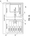
- the cargo inspection system 100 of the present invention comprises an X-ray source 102 and a detector array 104.
- the detector array 104 comprises a plurality of detectors 106 and a Source Intensity Controller (SIC) 108, which further comprises suitable electronics and interconnects to determine, for a given X-ray pulse, the X-ray transmission in the plurality of detectors 106 in the detector array 104 and to find the detector which has recorded the minimum transmission level.
- SIC Source Intensity Controller
- the SIC 108 determines whether the minimum transmission level is below a predetermined and preprogrammed first level A; or above a predetermined and preprogrammed first level A, but below a predetermined and preprogrammed second level, B; or above a predetermined and preprogrammed second level B.
- A has a value of 300 and B has a value of 600, in arbitrary units.
- the SIC can be implemented in a plurality of embodiments, as is obvious to those of ordinary skill in the art.
- the present invention employs a commercially available embedded computer with an FPGA.
- the FPGA interfaces to a custom I/O board which reads the signals from the detector array.
- the FPGA has custom firmware which performs the calculations described above, determines the required signal that needs to be sent to the X-ray source, and subsequently sends that signal to the X-ray source. It should also be noted herein, as evident to those of ordinary skill in the art, that it is possible to use an ASIC versus an FPGA.
- the SIC 108 sends a signal, either along an electrical and/or an optical connection, or wirelessly, to the X-ray source 102. If the minimum transmission level is below a predetermined and preprogrammed first level A, a first signal instructs the X-ray source 102 to increase its X-ray intensity for the next pulse. Optionally, if the minimum transmission level is above a predetermined and preprogrammed first level, A, but below a predetermined and preprogrammed second level B, a second signal instructs the source to stay at the same intensity. It should be noted, however, that the second signal may be eliminated and the source will stay at the same intensity by default.
- a third signal instructs the source to decrease its X-ray intensity for the next pulse.
- a fourth signal is used to instruct the source to perform the X-ray pulse itself. This last signal is sent after a predetermined period of time has elapsed for the source to settle in its new intensity setting.
- the present invention is capable of modulating the intensity of the X-ray source 102 on a pulse-to-pulse basis (i.e. in a few milliseconds).
- the X-ray source 102 is modified so that the system 100 is capable of pulse-to-pulse variation of intensity.
- the X-ray source 102 further comprises a linear accelerator 103.
- the X-ray source 102 further comprises a Source Intensity Control Receiver (SICR) 112, which is an electronics circuit that receives the signals from the SIC and performs the necessary functions to prepare the X-ray source 102 for the required intensity level for the next pulse.
- SICR Source Intensity Control Receiver
- the X-ray source 102 further comprises an apparatus and method to physically change the intensity level of the source for the next pulse.
- the X-ray source 102 further comprises a reference/monitor detector 114, which is read on each pulse to provide the exact intensity of the source during that pulse. Since monitor detectors are well-known to those of ordinary skill in the art for use with X-ray sources, they will not be described in detail herein.
- source intensity depends on three factors: the pulse duration, the peak current of electrons in the linac, and the pulse rate.
- the source intensity is modulated by changing the duration of the pulse, as described in greater detail below with respect to Figure 3 .
- Changing just the pulse duration as a method of modulating the X-ray intensity avoids a number of complications.
- Changing the pulse rate (number of pulses per second) is possible but requires major modifications to the inspection system operation.
- Changing the peak current of electrons in the accelerator is also possible, but this results in a change of an accelerator property called beam loading, as described below, and this affects the energy of the accelerated electrons.
- beam loading an accelerator property called beam loading
- the source intensity is modulated by changing the peak current.
- Changing the peak current also leads to a change in beam loading: while the electrons are drawing energy out of the accelerator structure, the available energy drops and subsequently, the electrons gain less energy.
- a change in the peak current changes the number of electrons being accelerated, which changes the beam loading, and thus, the amount of energy available for acceleration.
- a change in beam loading results, therefore, in a change in the final energy to which the electrons are accelerated. It is possible to use additional electronics to compensate for this by modifying modulator and RF source settings.
- the source intensity is modulated by changing the number of pulses per second.
- this method may be used with the present invention, conventional X-ray radiography systems use a single linac pulse to produce one column of pixels in the radiography image.
- the image resolution in the longitudinal direction (i.e. along the scan direction) in conventional systems.
- the present invention would have to be capable of producing many more pulses per second than conventional sources, and the detector system would have to integrate signals from different pulses over fixed time periods to produce one column of image data., i.e. each column of the image would now be the sum of a number of X-ray pulses, where before every pulse was used as a column in the image.
- the cargo inspection system uses the source intensity modulation systems and methods of the present invention as follows.
- An OSP is chosen so that it corresponds to one of the possibilities outlined above, and more specifically, equivalent to a conventional source, a factor of four (for a 6 MeV source) higher than the equivalent source, or somewhere between these two options.
- the OSP is defined as the maximum intensity it is allowed to put out (which may still be less than the rated intensity).
- the intensity-modulated system is then initialized to its lowest intensity setting.
- a single vertical line scan is then performed by the system at this intensity.
- the Source Intensity Controller electronics described above, in the cargo inspection system determines if any of the detectors of the system received less than a certain pre-determined threshold signal, A. If so, the electronics instructs the intensity-modulated source system to increase its output by some factor, for example, a factor of two.
- a second vertical line scan is performed at the new, higher, intensity. If any of the detectors still receive less than the threshold signal, A, the electronics repeats the request to the intensity-modulated source for an increase of a factor of two in intensity. This process repeats until either the intensity modulated source is at its OSP, or until the signal in each detector is above the threshold signal A.
- a different signal instructs the source to stay at the same intensity. It should be noted, however, that this signal may be eliminated and the source will stay at the same intensity by default and absent instruction from the signal.
- a signal instructs the source to decrease its X-ray intensity for the next pulse.
- the X-ray scanning system can include two detector arrays, adjacent to each other.
- the first array is specifically configured to measure the required source intensity for the next pulse (and not the transmission image), and second array is specifically configured to measure the transmission image (and not the required source intensity).
- the required intensity for the next pulse can be measured precisely. While increasing the number of detector arrays can increase the cost, it can also improve throughput through the inspection system.
- One of ordinary skill in the art would appreciate that other specialized detector arrays can be added and incorporated into the present invention.
- This new intensity value can, in one embodiment, be sent directly to the IMAXS source across an electrical connection in either analog or digital form, or across an optical connection in digital form.
- the equation above assumes that the x-ray source is capable of producing arbitrary intensities, or at least intensities close to those desired, in the range I min to I max . Further, such finely tuned intensity adjustments do not significantly improve performance.
- the intensity adjustments are, after all, based on the detector levels measured during the previous pulse. It is better to make larger steps in intensity (i.e. factors of two or so), to anticipate the case that more intensity may be needed than expected from the detector levels measured in the previous pulse.
- the function floor(x) finds the nearest integer smaller than x.
- formula (2) reduces to formula (1) if the function floor() is removed.
- the intensity is thus converted to a power of 2 times the maximum intensity (although other factors could be chosen than factors of 2).
- This new intensity after bounding it between I min and I max , can then be sent directly by electrical or optical connection to the x-ray source.
- I max may be arbitrarily normalized to 1, where 1, by convention, is then taken to be the OSP of the IMAXS source.
- the SIC must keep track of the current intensity, I cur .
- the threshold B is set to be 2 * A.
- Another signal is used to instruct the source to perform the X-ray pulse itself. This last signal is sent after sufficient time has elapsed for the source to settle in its new intensity setting. This process repeats until the end of the scan, and the source returns to its minimum intensity setting.
- the present invention will now be described, by way of example only, in use with a cargo inspection system that employs a conventional 6 MeV linac x-ray source.
- the intensity modulated x-ray source technology as described in the present invention may be used with any linac energy, typically ranging from 1 to 15 MeV.
- Figure 1b shows a cargo X-ray image 105, obtained using a cargo inspection system that employs a conventional 6 MeV linac X-ray source.
- the corresponding graph 110 shows minimum transmission pattern 115, maximum transmission line 120, standard source intensity line 125, and intensity-modulated source pattern 130, where the transmission is measured in vertical columns in the X-ray image having one column per X-ray pulse, over the course of the image.
- the intensity-modulated source pattern 130 depicts a source intensity line structure if an intensity modulated X-ray source was used. As shown in the image, there are many areas where the minimum transmission is fairly high (1,000-10,000 arbitrary units in the image) and only a few areas where the minimum transmission is very low. Conventional sources use the same fixed intensity 125, whereas the intensity-modulated source may have the intensity profile 130.
- Figure 2 is a graph 200 of the results of a calculation of the effect an IMAXS source would have had, using 1000 images obtained with a Rapiscan Systems, Inc. MSCS Eagle® system, which has a fixed-intensity 6 MeV x-ray source. As described above and shown in the graph, the average dose would have been reduced by a factor of 3, while maintaining equivalent image penetration. Further analysis of these images shows, that, with the same radiation footprint as a conventional source, the imaging penetration of a system using the intensity-modulated source of the present invention would have been approximately two inches of steel or steel-equivalent better.
- the present invention is capable of modulating the intensity of the source on a pulse-to-pulse basis (i.e. in a few milliseconds).
- the X-ray source is modified so that the system is capable of pulse-to-pulse variation of intensity.
- the X-ray source further comprises an SICR, which is an electronics circuit which receives the signals from the SIC and performs the necessary functions to prepare the source for the required intensity level for the next pulse.
- the source intensity is modulated by changing the duration of the pulse.
- pulsed linear electron accelerators usually have one of two types of electron guns: a diode gun or a gridded gun, also known as a triode gun.
- a diode gun a negative high voltage pulse on the cathode causes electrons to be emitted.
- the cathode is kept at a smaller, fixed negative high voltage, which by itself is insufficient to emit the electrons.
- a grid placed in front of the cathode is pulsed with a relatively small positive voltage. The combined voltages of the cathode and grid allow electrons to escape from the cathode.
- Figure 3 shows diagrams of the circuitry involved in both types of electron guns.
- diagram 305 shows the circuit for an accelerator with a diode gun
- diagram 310 shows the circuit for an accelerator with a triode or gridded gun.
- Figure 3 also depicts exemplary designs of additional retrofit circuitry 306 and 311 that allow for both types of electron guns to be used with the intensity-modulated source capability of the present invention. It should be noted that the designs are only exemplary and that the present invention is not limited to such designs.
- both retrofitting circuits 306 and 311 employ a delay generator 315. Between pulses, information from the inspection system detector array is used to preset delay generator 315 to a certain delay value, which, in one embodiment, ranges from 0 to the width of the RF pulse of the accelerator. If a diode gun circuit arrangement 305 is employed, the gun pulse is clamped to ground using a thyratron 320 after the delay, effectively shortening the pulse. Here, a shorter delay will cause fewer electrons to be generated and therefore decrease the intensity. If the triode gun circuit 310 is employed, a slightly different method is used - here, the delay is used to offset the RF pulse in time from the grid pulse.
- the same number of electrons is generated in each pulse, but only the electrons that are emitted within the RF pulse are accelerated. Varying the delay here causes a change in overlap between the grid and RF pulses and therefore a change in the number of accelerated electrons and in turn a change in intensity.
- Another triode gun choice is to change the injected pulse width by changing the pulse width of the grid pulse, thus reducing the injection of electrons into the accelerator.
- the triode or gridded gun 310 is employed as it has a relatively low grid voltage and can be timed more accurately.
- intensity modulated source systems and methods have been described above with respect to a fixed, portal inspection system, it is also possible to use the intensity-modulated source of the present invention with mobile (i.e. truck-mounted) applications.
- mobile applications i.e. truck-mounted
- shielding weight is one of the limiting factors for the possible X-ray sources that can be used, because of limits on the maximum truck and per-axle weights.
- Higher energy sources require more shielding and a heavier beam stop behind the detector array. Therefore, currently available mobile inspection systems have a maximum source energy of ⁇ 4.5 MeV. Since the intensity-modulated source of the present invention can lower the overall radiation footprint of the imaging system, it is possible to use a higher energy source with the same beam stop.
- the shielding for a linear accelerator consists mainly of lead, with the exception of a tungsten collimator close to the target. Lead is preferred as it is cheaper, however, the shielding weight of mostly-lead shielding is much greater than it would be for all-tungsten shielding, as will be explained below.
- shielding consists of a very dense, high-Z material in the form of a sphere around the target. Because the bremsstrahlung spectrum has higher intensity as well as higher energy in the forward direction, the sphere is not centered on the target, but offset by a distance D towards the front.
- Figure 5a shows the final results obtained using this type of simulation for lead. Shown in Figure 5a , graph 501, is the amount of lead (in linear cm) needed to shield the target at each angle. Since in the energy region of interest the mass attenuation coefficients of lead and tungsten are very similar, the results for tungsten can be computed from those for lead by simple multiplication by the ratio of the specific weights. For 90%-pure tungsten, the specific weight is 17.1 g/cc, and the ratio is 0.664. The resulting computed amount of tungsten required (in linear cm) is shown in Figure 5b in graph 503.
- a lead sphere of about 35 cm radius provides the same amount of shielding as a tungsten sphere of about 23 cm radius: the radius scales inversely with the specific weight.
- the volume of the sphere scales with the cube of the radius, and therefore with the inverse cube of the specific weight.
- the weight of the sphere scales with the inverse square of the specific weight.
- the weight of the tungsten sphere (-900 kg) is considerably smaller than that of the lead sphere (-2000 kg).
- FIG. 6 depicts one embodiment of a preferred shielding design 600 for a 6 MeV X-band accelerator.
- the overall weight of the accelerator, including shielding, supports, enclosure and RF unit is estimated to be approximately 1540 kg. This should be compared to the weight of the currently used 4.5 MeV S-band accelerator (including supports, enclosure and RF unit) of approximately 2630 kg.
- all-tungsten shielding could reduce the weight of a 6 MeV X-band source by about 40% compared to a 4.5 MeV S-band source, leaving room to convert some of the (expensive) tungsten shielding back to lead.
- an intensity-modulated source it is possible to improve the radiation footprint of cargo inspection systems and improve imaging penetration performance considerably. It is also possible to employ shielding designs that will allow higher energy sources to be used in conjunction with the intensity-modulated source of the present invention in mobile inspection applications. Alternatively, even higher-energy accelerators could be used, while still having a lower or similar overall weight.
- the intensity-modulating system and method of the present invention can be used with any inspection system.
- the system and method of the present invention can be used with an inspection system employing a dual-energy linear accelerator X-ray source, where the intensity is modulated concomitant with switching from a first energy to a second energy.
- the system and method of the present invention can be used with any inspection system employing a linear accelerator-based X-ray source, including portal systems, fixed systems, mobile systems, systems that operate in varying environments. Systems where personnel are exposed to scattered X-rays, such as portal systems, benefit most from the technology.
Landscapes
- Physics & Mathematics (AREA)
- General Physics & Mathematics (AREA)
- Life Sciences & Earth Sciences (AREA)
- Geophysics (AREA)
- General Life Sciences & Earth Sciences (AREA)
- High Energy & Nuclear Physics (AREA)
- Analytical Chemistry (AREA)
- General Health & Medical Sciences (AREA)
- Immunology (AREA)
- Pathology (AREA)
- Biochemistry (AREA)
- Chemical & Material Sciences (AREA)
- Health & Medical Sciences (AREA)
- Analysing Materials By The Use Of Radiation (AREA)
- X-Ray Techniques (AREA)
- Apparatus For Radiation Diagnosis (AREA)
Claims (14)
- Röntgen-Frachtabtastsystem, umfassend:eine Mehrzahl von Detektoren (106);gekennzeichnet durch Aufweisen einer Steuerung (108), die so konfiguriert ist, dass sie einen von einem der Mehrzahl von Detektoren (106) detektierten minimalen Röntgentransmissionsgrad empfängt und identifiziert, wobei die Steuerung (108) den minimalen Röntgentransmissionsgrad mit mindestens einem Schwellen-Transmissionsgrad vergleicht, und wobei die Steuerung basierend auf dem Vergleich ein Anpassungssignal erzeugt; undeine Röntgenquelle (102), die einen Linearbeschleuniger (103) mit einer Energie in einem Bereich von 1 MeV bis 15 MeV umfasst, wobei die Röntgenquelle das Anpassungssignal empfängt und so konfiguriert ist, dass sie eine Röntgenpulsdauer basierend auf dem Anpassungssignal anpasst.
- Röntgen-Frachtabtastsystem nach Anspruch 1, wobei die Röntgenquelle (103) eine Steuerung (112) umfasst, die das Anpassungssignal empfängt und eine Röntgenpulsdauer basierend auf dem Anpassungssignal anpasst.
- Röntgen-Frachtabtastsystem nach Anspruch 1, wobei die Steuerung (108) den minimalen Röntgentransmissionsgrad mit einer ersten vorbestimmten Schwelle vergleicht und, wenn der minimale Röntgentransmissionsgrad unter der ersten vorbestimmten Schwelle liegt, ein Anpassungssignal erzeugt, das die Röntgenquelle veranlasst, eine Röntgenpulsdauer zu verlängern.
- Röntgen-Frachtkontrollsystem nach Anspruch 1, wobei die Steuerung (108) den minimalen Röntgentransmissionsgrad mit einer ersten vorbestimmten Schwelle und einer zweiten vorbestimmten Schwelle vergleicht und,
wenn der minimale Röntgentransmissionsgrad über der ersten vorbestimmten Schwelle, aber unter der zweiten vorbestimmten Schwelle liegt, ein Anpassungssignal erzeugt, das die Röntgenquelle (102) veranlasst, eine Röntgenpulsdauer nicht zu modifizieren; oder
wenn der minimale Röntgentransmissionsgrad über der zweiten vorbestimmten Schwelle liegt, ein Anpassungssignal erzeugt, das die Röntgenquelle (102) veranlasst, eine Röntgenpulsdauer zu verkürzen. - Röntgen-Frachtkontrollsystem nach Anspruch 1, wobei die Steuerung (108) einen Computer mit einer Verarbeitungseinheit umfasst, und wobei die Verarbeitungseinheit über eine Schnittstelle mit einer Eingabe-/Ausgabe-Platine verbunden ist, welche Signale von mindestens einem der Mehrzahl von Detektoren (106) empfängt, und gegebenenfalls:wobei die Verarbeitungseinheit mindestens eines von einem feldprogrammierbaren Gate-Array oder einer anwendungsspezifischen integrierten Schaltung ist.
- Röntgen-Frachtkontrollsystem nach Anspruch 1, wobei die Mehrzahl von Detektoren (106) eine erste Detektoranordnung, wobei die erste Detektoranordnung zum Messen einer erforderlichen Quellenintensität für einen anschließenden Röntgenpuls konfiguriert ist, und eine zweite Detektoranordnung umfasst, wobei die zweite Detektoranordnung zum Messen eines Transmissionsbildes und nicht der erforderlichen Quellenintensität konfiguriert ist.
- Röntgen-Frachtabtastsystem nach Anspruch 1, wobei die Röntgenquelle (102) so konfiguriert ist, dass sie eine Dauer eines zweiten Röntgenpulses basierend auf einem Anpassungssignal anpasst, das von einem ersten Röntgenpuls erzeugt wird, der unmittelbar vor dem zweiten Röntgenpuls auftritt.
- Verfahren zur Umrüstung eines bestehenden Röntgen-Frachtabtastsystems mit einer Röntgenquelle (102), die einen Linearbeschleuniger (103) mit einer Energie in einem Bereich von 1 MeV bis 15 MeV, einer Durchdringungsfähigkeit und einem Strahlungsfußabdruck umfasst, und einer Mehrzahl von Detektoren (106), umfassend ein Installieren einer Steuerung (108), dadurch gekennzeichnet, dass die Steuerung (108) so konfiguriert ist, dass sie einen von einem der Mehrzahl von Detektoren (106) detektierten minimalen Röntgentransmissionsgrad empfängt und identifiziert, wobei die Steuerung (108) den minimalen Röntgentransmissionsgrad mit mindestens einem Schwellen-Durchlässigkeitsgrad vergleicht, und wobei die Steuerung basierend auf dem Vergleich ein Anpassungssignal erzeugt, wobei das Anpassungssignal so konfiguriert ist, dass es eine Röntgenpulsdauer basierend auf dem Anpassungssignal anpasst.
- Verfahren nach Anspruch 8, wobei die Durchdringungsfähigkeit um eine Distanz im Bereich von 1 cm bis 10 cm erhöht wird; oder
wobei der Strahlungsfußabdruck um einen Faktor zwischen 1 und 9 verbessert wird. - Verfahren nach Anspruch 8, wobei die Steuerung den minimalen Röntgentransmissionsgrad mit einer ersten vorbestimmten Schwelle vergleicht und, wenn der minimale Röntgentransmissionsgrad unter der ersten vorbestimmten Schwelle liegt, ein Anpassungssignal erzeugt, das die Röntgenquelle veranlasst, eine Röntgenpulsdauer zu verlängern.
- Verfahren nach Anspruch 8, wobei die Steuerung (108) den minimalen Röntgentransmissionsgrad mit einer ersten vorbestimmten Schwelle und einer zweiten vorbestimmten Schwelle vergleicht und,
wenn der minimale Röntgentransmissionsgrad über der ersten vorbestimmten Schwelle, aber unter der zweiten vorbestimmten Schwelle liegt, ein Anpassungssignal erzeugt, das die Röntgenquelle (102) veranlasst, eine Röntgenpulsdauer nicht zu modifizieren; oder
wenn der minimale Röntgentransmissionsgrad über der zweiten vorbestimmten Schwelle liegt, ein Anpassungssignal erzeugt, das die Röntgenquelle (102) veranlasst, eine Röntgenpulsdauer zu verkürzen. - Verfahren nach Anspruch 9, wobei die Steuerung einen Computer mit einer Verarbeitungseinheit umfasst, und wobei die Verarbeitungseinheit über eine Schnittstelle mit einer Eingabe-/Ausgabe-Platine verbunden ist, welche Signale von mindestens einem der Mehrzahl von Detektoren empfängt.
- Verfahren nach Anspruch 8, wobei die Mehrzahl von Detektoren (106) eine erste Detektoranordnung, wobei die erste Detektoranordnung zum Messen einer erforderlichen Quellenintensität für einen anschließenden Röntgenpuls konfiguriert ist, und eine zweite Detektoranordnung umfasst, wobei die zweite Detektoranordnung zum Messen eines Transmissionsbildes und nicht der erforderlichen Quellenintensität konfiguriert ist.
- Verfahren nach Anspruch 8, wobei die Röntgenquelle (102) so konfiguriert ist, dass sie eine Dauer eines zweiten Röntgenpulses basierend auf einem Anpassungssignal anpasst, das von einem ersten Röntgenpuls erzeugt wird, der unmittelbar vor dem zweiten Röntgenpuls auftritt.
Priority Applications (3)
| Application Number | Priority Date | Filing Date | Title |
|---|---|---|---|
| EP17194449.9A EP3287773B1 (de) | 2008-08-11 | 2009-06-12 | Systeme und verfahren zur verwendung einer intensitätsmodulierten röntgenquelle |
| PL09807013T PL2327281T3 (pl) | 2008-08-11 | 2009-06-12 | Systemy i sposoby wykorzystywania źródła promieniowania rentgenowskiego o modulowanym natężeniu |
| PL17194449T PL3287773T3 (pl) | 2008-08-11 | 2009-06-12 | Systemy i sposoby wykorzystywania źródła promieniowania rentgenowskiego o modulowanym natężeniu |
Applications Claiming Priority (2)
| Application Number | Priority Date | Filing Date | Title |
|---|---|---|---|
| US8781008P | 2008-08-11 | 2008-08-11 | |
| PCT/US2009/047292 WO2010019311A2 (en) | 2008-08-11 | 2009-06-12 | Systems and methods for using an intensity-modulated x-ray source |
Related Child Applications (2)
| Application Number | Title | Priority Date | Filing Date |
|---|---|---|---|
| EP17194449.9A Division EP3287773B1 (de) | 2008-08-11 | 2009-06-12 | Systeme und verfahren zur verwendung einer intensitätsmodulierten röntgenquelle |
| EP17194449.9A Division-Into EP3287773B1 (de) | 2008-08-11 | 2009-06-12 | Systeme und verfahren zur verwendung einer intensitätsmodulierten röntgenquelle |
Publications (3)
| Publication Number | Publication Date |
|---|---|
| EP2327281A2 EP2327281A2 (de) | 2011-06-01 |
| EP2327281A4 EP2327281A4 (de) | 2015-03-18 |
| EP2327281B1 true EP2327281B1 (de) | 2017-11-29 |
Family
ID=41652970
Family Applications (2)
| Application Number | Title | Priority Date | Filing Date |
|---|---|---|---|
| EP17194449.9A Active EP3287773B1 (de) | 2008-08-11 | 2009-06-12 | Systeme und verfahren zur verwendung einer intensitätsmodulierten röntgenquelle |
| EP09807013.9A Active EP2327281B1 (de) | 2008-08-11 | 2009-06-12 | Systeme und verfahren zur verwendung einer intensitätsmodulierten röntgenquelle |
Family Applications Before (1)
| Application Number | Title | Priority Date | Filing Date |
|---|---|---|---|
| EP17194449.9A Active EP3287773B1 (de) | 2008-08-11 | 2009-06-12 | Systeme und verfahren zur verwendung einer intensitätsmodulierten röntgenquelle |
Country Status (7)
| Country | Link |
|---|---|
| US (3) | US8054937B2 (de) |
| EP (2) | EP3287773B1 (de) |
| JP (1) | JP6000549B2 (de) |
| CN (2) | CN107782751B (de) |
| HK (2) | HK1251298A1 (de) |
| PL (2) | PL2327281T3 (de) |
| WO (1) | WO2010019311A2 (de) |
Families Citing this family (47)
| Publication number | Priority date | Publication date | Assignee | Title |
|---|---|---|---|---|
| US8275091B2 (en) | 2002-07-23 | 2012-09-25 | Rapiscan Systems, Inc. | Compact mobile cargo scanning system |
| US7963695B2 (en) | 2002-07-23 | 2011-06-21 | Rapiscan Systems, Inc. | Rotatable boom cargo scanning system |
| US6928141B2 (en) | 2003-06-20 | 2005-08-09 | Rapiscan, Inc. | Relocatable X-ray imaging system and method for inspecting commercial vehicles and cargo containers |
| US7471764B2 (en) | 2005-04-15 | 2008-12-30 | Rapiscan Security Products, Inc. | X-ray imaging system having improved weather resistance |
| US7526064B2 (en) | 2006-05-05 | 2009-04-28 | Rapiscan Security Products, Inc. | Multiple pass cargo inspection system |
| GB0809110D0 (en) | 2008-05-20 | 2008-06-25 | Rapiscan Security Products Inc | Gantry scanner systems |
| JP6000549B2 (ja) * | 2008-08-11 | 2016-09-28 | ラピスカン ラボラトリーズ、インコーポレイテッド | 強度変調x線源を用いたシステム及び方法 |
| EP2347289A1 (de) * | 2008-10-14 | 2011-07-27 | Analogic Corporation | Strahlungsmodulation in einer sicherheitsuntersuchungsvorrichtung |
| US8232748B2 (en) * | 2009-01-26 | 2012-07-31 | Accuray, Inc. | Traveling wave linear accelerator comprising a frequency controller for interleaved multi-energy operation |
| US8203289B2 (en) * | 2009-07-08 | 2012-06-19 | Accuray, Inc. | Interleaving multi-energy x-ray energy operation of a standing wave linear accelerator using electronic switches |
| CN102686999B (zh) | 2009-10-29 | 2017-02-08 | 拉皮斯坎系统股份有限公司 | 移动式飞机检查系统 |
| US8311187B2 (en) | 2010-01-29 | 2012-11-13 | Accuray, Inc. | Magnetron powered linear accelerator for interleaved multi-energy operation |
| GB201001736D0 (en) | 2010-02-03 | 2010-03-24 | Rapiscan Security Products Inc | Scanning systems |
| GB201001738D0 (en) | 2010-02-03 | 2010-03-24 | Rapiscan Lab Inc | Scanning systems |
| US8284898B2 (en) | 2010-03-05 | 2012-10-09 | Accuray, Inc. | Interleaving multi-energy X-ray energy operation of a standing wave linear accelerator |
| US8942351B2 (en) | 2010-10-01 | 2015-01-27 | Accuray Incorporated | Systems and methods for cargo scanning and radiotherapy using a traveling wave linear accelerator based X-ray source using pulse width to modulate pulse-to-pulse dosage |
| US9167681B2 (en) | 2010-10-01 | 2015-10-20 | Accuray, Inc. | Traveling wave linear accelerator based x-ray source using current to modulate pulse-to-pulse dosage |
| US8836250B2 (en) | 2010-10-01 | 2014-09-16 | Accuray Incorporated | Systems and methods for cargo scanning and radiotherapy using a traveling wave linear accelerator based x-ray source using current to modulate pulse-to-pulse dosage |
| US9258876B2 (en) | 2010-10-01 | 2016-02-09 | Accuray, Inc. | Traveling wave linear accelerator based x-ray source using pulse width to modulate pulse-to-pulse dosage |
| DE102011075210B4 (de) * | 2011-05-04 | 2016-03-24 | Siemens Aktiengesellschaft | Linearbeschleuniger |
| US9218933B2 (en) | 2011-06-09 | 2015-12-22 | Rapidscan Systems, Inc. | Low-dose radiographic imaging system |
| WO2012170914A1 (en) | 2011-06-09 | 2012-12-13 | Rapiscan Systems, Inc. | System and method for x-ray source weight reduction |
| US9274065B2 (en) | 2012-02-08 | 2016-03-01 | Rapiscan Systems, Inc. | High-speed security inspection system |
| EP2812736A2 (de) * | 2012-02-10 | 2014-12-17 | Smiths Heimann GmbH | Verfahren und vorrichtung zur überprüfung des laderaums eines lastkraftwagens |
| MX350070B (es) | 2013-01-31 | 2017-08-25 | Rapiscan Systems Inc | Sistema de inspeccion de seguridad portatil. |
| WO2014124152A2 (en) * | 2013-02-06 | 2014-08-14 | Rapiscan Systems, Inc. | Systems and methods for x-ray source weight reduction |
| CN104244561A (zh) | 2013-06-21 | 2014-12-24 | 同方威视技术股份有限公司 | 驻波电子直线加速器及集装箱/车辆检查系统 |
| US9086496B2 (en) * | 2013-11-15 | 2015-07-21 | Varian Medical Systems, Inc. | Feedback modulated radiation scanning systems and methods for reduced radiological footprint |
| US9622333B2 (en) | 2014-02-27 | 2017-04-11 | Etm Electromatic, Inc | Linear accelerator system with stable interleaved and intermittent pulsing |
| US10459111B2 (en) * | 2014-05-23 | 2019-10-29 | Radiabeam Technologies, Llc | System and method for adaptive X-ray cargo inspection |
| US10955367B2 (en) | 2015-09-08 | 2021-03-23 | American Science And Engineering, Inc. | Backscatter imaging for precision agriculture |
| US11536672B2 (en) | 2015-09-08 | 2022-12-27 | American Science And Engineering, Inc. | Systems and methods for using backscatter imaging in precision agriculture |
| CN106815769B (zh) * | 2015-11-27 | 2020-07-28 | 华北电力大学 | 核电厂点源线源组合的复合辐射源强逆推方法及系统 |
| CN105548223B (zh) | 2015-12-23 | 2019-07-02 | 清华大学 | 扫描方法、扫描系统及射线扫描控制器 |
| GB2567115B (en) | 2016-07-14 | 2022-08-10 | Rapiscan Systems Inc | Systems and methods for improving penetration of radiographic scanners |
| CN106132058A (zh) * | 2016-08-23 | 2016-11-16 | 苏州雷泰医疗科技有限公司 | 一种同源多能加速器及加速器治疗装置 |
| CN106841242B (zh) * | 2017-01-23 | 2019-02-22 | 刘智慧 | 探测方法与装置 |
| US11165427B2 (en) * | 2018-05-18 | 2021-11-02 | Varex Imaging Corporation | Configurable linear accelerator frequency control system and method |
| CN110333230A (zh) * | 2019-05-06 | 2019-10-15 | 丹东市阳光仪器有限公司 | 无损探测爬行器管道内曝光时长调时方法 |
| WO2020242511A1 (en) * | 2019-05-31 | 2020-12-03 | American Science And Engineering, Inc. | Method and system for timing the injections of electron beams in a multi-energy x-ray cargo inspection system |
| US20210041378A1 (en) * | 2019-08-11 | 2021-02-11 | Rapiscan Systems, Inc. | Systems and Methods for Using Three-Dimensional X-Ray Imaging in Meat Production and Processing Applications |
| US11193898B1 (en) | 2020-06-01 | 2021-12-07 | American Science And Engineering, Inc. | Systems and methods for controlling image contrast in an X-ray system |
| CN115697202B (zh) | 2020-06-01 | 2025-08-08 | 美国科学及工程股份有限公司 | 用于在x射线系统中控制图像对比度的系统和方法 |
| EP4346392A4 (de) | 2021-06-02 | 2024-08-28 | Michael Stapleton Associates, Ltd. | Aufzeichnung von hundeinspektionen |
| WO2023150418A2 (en) | 2022-02-03 | 2023-08-10 | Rapiscan Holdings, Inc. | Systems and methods for real-time energy and dose monitoring of an x-ray linear accelerator |
| CN114755707B (zh) * | 2022-04-12 | 2025-09-02 | 北京合鲸科技发展有限公司 | 放射性自适应测量方法、测量装置 |
| WO2024196442A1 (en) | 2023-03-17 | 2024-09-26 | Rapiscan Holdings, Inc. | Systems and methods for monitoring output energy of a high-energy x-ray source |
Citations (1)
| Publication number | Priority date | Publication date | Assignee | Title |
|---|---|---|---|---|
| WO2001059485A1 (en) * | 2000-02-10 | 2001-08-16 | American Science And Engineering, Inc. | Spectrally shaped x-ray inspection system |
Family Cites Families (32)
| Publication number | Priority date | Publication date | Assignee | Title |
|---|---|---|---|---|
| US3919467A (en) | 1973-08-27 | 1975-11-11 | Ridge Instr Company Inc | X-ray baggage inspection system |
| JPS53110495A (en) * | 1977-03-09 | 1978-09-27 | Toshiba Corp | Radiation tomograph ic device |
| US5040199A (en) | 1986-07-14 | 1991-08-13 | Hologic, Inc. | Apparatus and method for analysis using x-rays |
| JP3109530B2 (ja) * | 1991-02-28 | 2000-11-20 | 株式会社島津製作所 | X線撮影装置 |
| US5319696A (en) * | 1992-10-05 | 1994-06-07 | General Electric Company | X-ray dose reduction in pulsed systems by adaptive X-ray pulse adjustment |
| US5321271A (en) * | 1993-03-30 | 1994-06-14 | Intraop, Inc. | Intraoperative electron beam therapy system and facility |
| US6438201B1 (en) * | 1994-11-23 | 2002-08-20 | Lunar Corporation | Scanning densitometry system with adjustable X-ray tube current |
| US5661377A (en) * | 1995-02-17 | 1997-08-26 | Intraop Medical, Inc. | Microwave power control apparatus for linear accelerator using hybrid junctions |
| US5608774A (en) | 1995-06-23 | 1997-03-04 | Science Applications International Corporation | Portable, digital X-ray apparatus for producing, storing, and displaying electronic radioscopic images |
| US5838759A (en) * | 1996-07-03 | 1998-11-17 | Advanced Research And Applications Corporation | Single beam photoneutron probe and X-ray imaging system for contraband detection and identification |
| US5974111A (en) * | 1996-09-24 | 1999-10-26 | Vivid Technologies, Inc. | Identifying explosives or other contraband by employing transmitted or scattered X-rays |
| US5949811A (en) * | 1996-10-08 | 1999-09-07 | Hitachi Medical Corporation | X-ray apparatus |
| US6249567B1 (en) | 1998-12-01 | 2001-06-19 | American Science & Engineering, Inc. | X-ray back scatter imaging system for undercarriage inspection |
| JP4260966B2 (ja) * | 1999-03-12 | 2009-04-30 | 株式会社東芝 | X線コンピュータ断層撮影装置 |
| US6713773B1 (en) | 1999-10-07 | 2004-03-30 | Mitec, Inc. | Irradiation system and method |
| US20080211431A1 (en) * | 2000-02-10 | 2008-09-04 | American Science And Engineering, Inc. | Pulse-to-Pulse-Switchable Multiple-Energy Linear Accelerators Based on Fast RF Power Switching |
| US7538325B2 (en) | 2000-02-10 | 2009-05-26 | American Science And Engineering, Inc. | Single-pulse-switched multiple energy X-ray source applications |
| US7010094B2 (en) | 2000-02-10 | 2006-03-07 | American Science And Engineering, Inc. | X-ray inspection using spatially and spectrally tailored beams |
| US20050117683A1 (en) * | 2000-02-10 | 2005-06-02 | Andrey Mishin | Multiple energy x-ray source for security applications |
| FI111759B (fi) * | 2000-03-14 | 2003-09-15 | Planmed Oy | Anturijärjestelmä ja menetelmä digitaalisessa röntgenkuvantamisessa |
| JP3525865B2 (ja) * | 2000-06-29 | 2004-05-10 | 株式会社島津製作所 | X線透視装置 |
| WO2004095060A2 (en) * | 2003-04-23 | 2004-11-04 | L-3 Communications Security and Detection Systems Corporation | X-ray imaging technique |
| JP4475916B2 (ja) * | 2003-10-27 | 2010-06-09 | 株式会社日立メディコ | X線ct装置 |
| JP4537037B2 (ja) * | 2003-11-11 | 2010-09-01 | 東芝Itコントロールシステム株式会社 | X線検査装置及びその管電圧・管電流調整方法 |
| RU2346996C2 (ru) | 2004-06-29 | 2009-02-20 | ЮРОПИЭН НИКЕЛЬ ПиЭлСи | Усовершенствованное выщелачивание основных металлов |
| US7272208B2 (en) * | 2004-09-21 | 2007-09-18 | Ge Medical Systems Global Technology Company, Llc | System and method for an adaptive morphology x-ray beam in an x-ray system |
| DE102005006895B4 (de) * | 2005-02-15 | 2010-11-18 | Siemens Ag | Röntgendiagnostikeinrichtung sowie Verfahren zu deren Regelung |
| JP2007093501A (ja) * | 2005-09-30 | 2007-04-12 | Ishikawajima Inspection & Instrumentation Co | X線検査装置のデータ採取システム |
| CN101076218B (zh) * | 2006-05-19 | 2011-05-11 | 清华大学 | 产生具有不同能量的x射线的设备、方法及材料识别系统 |
| CZ201016A3 (cs) | 2007-06-22 | 2010-06-23 | Opynen@Adam Van | Nástavec pro rozširovac trubek, sestava pro ovládání rozširovace trubek a zpusob využívání tohoto rozširovace trubek |
| GB0803646D0 (en) | 2008-02-28 | 2008-04-02 | Rapiscan Security Products Inc | Scanning systems |
| JP6000549B2 (ja) | 2008-08-11 | 2016-09-28 | ラピスカン ラボラトリーズ、インコーポレイテッド | 強度変調x線源を用いたシステム及び方法 |
-
2009
- 2009-06-12 JP JP2011523012A patent/JP6000549B2/ja active Active
- 2009-06-12 WO PCT/US2009/047292 patent/WO2010019311A2/en not_active Ceased
- 2009-06-12 PL PL09807013T patent/PL2327281T3/pl unknown
- 2009-06-12 US US12/484,172 patent/US8054937B2/en not_active Expired - Fee Related
- 2009-06-12 EP EP17194449.9A patent/EP3287773B1/de active Active
- 2009-06-12 PL PL17194449T patent/PL3287773T3/pl unknown
- 2009-06-12 CN CN201710916561.XA patent/CN107782751B/zh active Active
- 2009-06-12 CN CN200980140400XA patent/CN102440078A/zh active Pending
- 2009-06-12 EP EP09807013.9A patent/EP2327281B1/de active Active
-
2011
- 2011-09-29 US US13/248,079 patent/US8437448B2/en not_active Expired - Fee Related
-
2013
- 2013-04-10 US US13/860,458 patent/US8781067B2/en not_active Expired - Fee Related
-
2018
- 2018-08-16 HK HK18110515.5A patent/HK1251298A1/en unknown
- 2018-08-28 HK HK18111058.6A patent/HK1251656A1/zh unknown
Patent Citations (1)
| Publication number | Priority date | Publication date | Assignee | Title |
|---|---|---|---|---|
| WO2001059485A1 (en) * | 2000-02-10 | 2001-08-16 | American Science And Engineering, Inc. | Spectrally shaped x-ray inspection system |
Also Published As
| Publication number | Publication date |
|---|---|
| PL3287773T3 (pl) | 2021-10-25 |
| US20120257719A1 (en) | 2012-10-11 |
| EP2327281A4 (de) | 2015-03-18 |
| CN102440078A (zh) | 2012-05-02 |
| WO2010019311A2 (en) | 2010-02-18 |
| US8437448B2 (en) | 2013-05-07 |
| JP2012510043A (ja) | 2012-04-26 |
| HK1251656A1 (zh) | 2019-02-01 |
| WO2010019311A3 (en) | 2012-05-24 |
| EP3287773A1 (de) | 2018-02-28 |
| PL2327281T3 (pl) | 2018-10-31 |
| CN107782751B (zh) | 2021-10-26 |
| CN107782751A (zh) | 2018-03-09 |
| HK1251298A1 (en) | 2019-01-25 |
| EP2327281A2 (de) | 2011-06-01 |
| EP3287773B1 (de) | 2021-03-03 |
| US8781067B2 (en) | 2014-07-15 |
| US20130329855A1 (en) | 2013-12-12 |
| US8054937B2 (en) | 2011-11-08 |
| US20100034355A1 (en) | 2010-02-11 |
| JP6000549B2 (ja) | 2016-09-28 |
Similar Documents
| Publication | Publication Date | Title |
|---|---|---|
| EP2327281B1 (de) | Systeme und verfahren zur verwendung einer intensitätsmodulierten röntgenquelle | |
| US7646851B2 (en) | Device and method for generating X-rays having different energy levels and material discrimination system | |
| CN102822696B (zh) | 扫描系统 | |
| US7130371B2 (en) | System for alternately pulsing energy of accelerated electrons bombarding a conversion target | |
| US9348040B2 (en) | Adaptive scanning in an imaging system | |
| US9086496B2 (en) | Feedback modulated radiation scanning systems and methods for reduced radiological footprint | |
| US20200163199A1 (en) | Source for Intra-Pulse Multi-Energy X-Ray Cargo Inspection | |
| US20230245847A1 (en) | Systems and Methods for Real-Time Energy and Dose Monitoring of an X-Ray Linear Accelerator | |
| PL218303B1 (pl) | Sposób wytwarzania dwuenergetycznych, cyklicznych impulsów promieniowania X oraz liniowy dwuenergetyczny akcelerator elektronów |
Legal Events
| Date | Code | Title | Description |
|---|---|---|---|
| PUAI | Public reference made under article 153(3) epc to a published international application that has entered the european phase |
Free format text: ORIGINAL CODE: 0009012 |
|
| 17P | Request for examination filed |
Effective date: 20110310 |
|
| AK | Designated contracting states |
Kind code of ref document: A2 Designated state(s): AT BE BG CH CY CZ DE DK EE ES FI FR GB GR HR HU IE IS IT LI LT LU LV MC MK MT NL NO PL PT RO SE SI SK TR |
|
| AX | Request for extension of the european patent |
Extension state: AL BA RS |
|
| DAX | Request for extension of the european patent (deleted) | ||
| R17D | Deferred search report published (corrected) |
Effective date: 20120524 |
|
| RIC1 | Information provided on ipc code assigned before grant |
Ipc: G01N 23/04 20060101AFI20120704BHEP |
|
| REG | Reference to a national code |
Ref country code: DE Ref legal event code: R079 Ref document number: 602009049656 Country of ref document: DE Free format text: PREVIOUS MAIN CLASS: H05G0001300000 Ipc: G01N0023040000 |
|
| A4 | Supplementary search report drawn up and despatched |
Effective date: 20150213 |
|
| RIC1 | Information provided on ipc code assigned before grant |
Ipc: G01N 23/04 20060101AFI20150209BHEP |
|
| GRAP | Despatch of communication of intention to grant a patent |
Free format text: ORIGINAL CODE: EPIDOSNIGR1 |
|
| STAA | Information on the status of an ep patent application or granted ep patent |
Free format text: STATUS: GRANT OF PATENT IS INTENDED |
|
| INTG | Intention to grant announced |
Effective date: 20170601 |
|
| GRAS | Grant fee paid |
Free format text: ORIGINAL CODE: EPIDOSNIGR3 |
|
| GRAA | (expected) grant |
Free format text: ORIGINAL CODE: 0009210 |
|
| STAA | Information on the status of an ep patent application or granted ep patent |
Free format text: STATUS: THE PATENT HAS BEEN GRANTED |
|
| AK | Designated contracting states |
Kind code of ref document: B1 Designated state(s): AT BE BG CH CY CZ DE DK EE ES FI FR GB GR HR HU IE IS IT LI LT LU LV MC MK MT NL NO PL PT RO SE SI SK TR |
|
| REG | Reference to a national code |
Ref country code: CH Ref legal event code: EP |
|
| REG | Reference to a national code |
Ref country code: AT Ref legal event code: REF Ref document number: 950841 Country of ref document: AT Kind code of ref document: T Effective date: 20171215 |
|
| REG | Reference to a national code |
Ref country code: IE Ref legal event code: FG4D |
|
| REG | Reference to a national code |
Ref country code: DE Ref legal event code: R096 Ref document number: 602009049656 Country of ref document: DE |
|
| REG | Reference to a national code |
Ref country code: NL Ref legal event code: MP Effective date: 20171129 |
|
| REG | Reference to a national code |
Ref country code: LT Ref legal event code: MG4D |
|
| REG | Reference to a national code |
Ref country code: AT Ref legal event code: MK05 Ref document number: 950841 Country of ref document: AT Kind code of ref document: T Effective date: 20171129 |
|
| PG25 | Lapsed in a contracting state [announced via postgrant information from national office to epo] |
Ref country code: FI Free format text: LAPSE BECAUSE OF FAILURE TO SUBMIT A TRANSLATION OF THE DESCRIPTION OR TO PAY THE FEE WITHIN THE PRESCRIBED TIME-LIMIT Effective date: 20171129 Ref country code: SE Free format text: LAPSE BECAUSE OF FAILURE TO SUBMIT A TRANSLATION OF THE DESCRIPTION OR TO PAY THE FEE WITHIN THE PRESCRIBED TIME-LIMIT Effective date: 20171129 Ref country code: ES Free format text: LAPSE BECAUSE OF FAILURE TO SUBMIT A TRANSLATION OF THE DESCRIPTION OR TO PAY THE FEE WITHIN THE PRESCRIBED TIME-LIMIT Effective date: 20171129 Ref country code: LT Free format text: LAPSE BECAUSE OF FAILURE TO SUBMIT A TRANSLATION OF THE DESCRIPTION OR TO PAY THE FEE WITHIN THE PRESCRIBED TIME-LIMIT Effective date: 20171129 Ref country code: NO Free format text: LAPSE BECAUSE OF FAILURE TO SUBMIT A TRANSLATION OF THE DESCRIPTION OR TO PAY THE FEE WITHIN THE PRESCRIBED TIME-LIMIT Effective date: 20180228 |
|
| RAP2 | Party data changed (patent owner data changed or rights of a patent transferred) |
Owner name: RAPISCAN LABORATORIES, INC. |
|
| PG25 | Lapsed in a contracting state [announced via postgrant information from national office to epo] |
Ref country code: AT Free format text: LAPSE BECAUSE OF FAILURE TO SUBMIT A TRANSLATION OF THE DESCRIPTION OR TO PAY THE FEE WITHIN THE PRESCRIBED TIME-LIMIT Effective date: 20171129 Ref country code: GR Free format text: LAPSE BECAUSE OF FAILURE TO SUBMIT A TRANSLATION OF THE DESCRIPTION OR TO PAY THE FEE WITHIN THE PRESCRIBED TIME-LIMIT Effective date: 20180301 Ref country code: LV Free format text: LAPSE BECAUSE OF FAILURE TO SUBMIT A TRANSLATION OF THE DESCRIPTION OR TO PAY THE FEE WITHIN THE PRESCRIBED TIME-LIMIT Effective date: 20171129 Ref country code: HR Free format text: LAPSE BECAUSE OF FAILURE TO SUBMIT A TRANSLATION OF THE DESCRIPTION OR TO PAY THE FEE WITHIN THE PRESCRIBED TIME-LIMIT Effective date: 20171129 Ref country code: BG Free format text: LAPSE BECAUSE OF FAILURE TO SUBMIT A TRANSLATION OF THE DESCRIPTION OR TO PAY THE FEE WITHIN THE PRESCRIBED TIME-LIMIT Effective date: 20180228 |
|
| REG | Reference to a national code |
Ref country code: FR Ref legal event code: PLFP Year of fee payment: 10 |
|
| PG25 | Lapsed in a contracting state [announced via postgrant information from national office to epo] |
Ref country code: NL Free format text: LAPSE BECAUSE OF FAILURE TO SUBMIT A TRANSLATION OF THE DESCRIPTION OR TO PAY THE FEE WITHIN THE PRESCRIBED TIME-LIMIT Effective date: 20171129 |
|
| PG25 | Lapsed in a contracting state [announced via postgrant information from national office to epo] |
Ref country code: SK Free format text: LAPSE BECAUSE OF FAILURE TO SUBMIT A TRANSLATION OF THE DESCRIPTION OR TO PAY THE FEE WITHIN THE PRESCRIBED TIME-LIMIT Effective date: 20171129 Ref country code: DK Free format text: LAPSE BECAUSE OF FAILURE TO SUBMIT A TRANSLATION OF THE DESCRIPTION OR TO PAY THE FEE WITHIN THE PRESCRIBED TIME-LIMIT Effective date: 20171129 Ref country code: CZ Free format text: LAPSE BECAUSE OF FAILURE TO SUBMIT A TRANSLATION OF THE DESCRIPTION OR TO PAY THE FEE WITHIN THE PRESCRIBED TIME-LIMIT Effective date: 20171129 Ref country code: EE Free format text: LAPSE BECAUSE OF FAILURE TO SUBMIT A TRANSLATION OF THE DESCRIPTION OR TO PAY THE FEE WITHIN THE PRESCRIBED TIME-LIMIT Effective date: 20171129 Ref country code: CY Free format text: LAPSE BECAUSE OF FAILURE TO SUBMIT A TRANSLATION OF THE DESCRIPTION OR TO PAY THE FEE WITHIN THE PRESCRIBED TIME-LIMIT Effective date: 20171129 |
|
| REG | Reference to a national code |
Ref country code: DE Ref legal event code: R097 Ref document number: 602009049656 Country of ref document: DE |
|
| PG25 | Lapsed in a contracting state [announced via postgrant information from national office to epo] |
Ref country code: RO Free format text: LAPSE BECAUSE OF FAILURE TO SUBMIT A TRANSLATION OF THE DESCRIPTION OR TO PAY THE FEE WITHIN THE PRESCRIBED TIME-LIMIT Effective date: 20171129 Ref country code: IT Free format text: LAPSE BECAUSE OF FAILURE TO SUBMIT A TRANSLATION OF THE DESCRIPTION OR TO PAY THE FEE WITHIN THE PRESCRIBED TIME-LIMIT Effective date: 20171129 |
|
| PLBE | No opposition filed within time limit |
Free format text: ORIGINAL CODE: 0009261 |
|
| STAA | Information on the status of an ep patent application or granted ep patent |
Free format text: STATUS: NO OPPOSITION FILED WITHIN TIME LIMIT |
|
| 26N | No opposition filed |
Effective date: 20180830 |
|
| PG25 | Lapsed in a contracting state [announced via postgrant information from national office to epo] |
Ref country code: SI Free format text: LAPSE BECAUSE OF FAILURE TO SUBMIT A TRANSLATION OF THE DESCRIPTION OR TO PAY THE FEE WITHIN THE PRESCRIBED TIME-LIMIT Effective date: 20171129 |
|
| REG | Reference to a national code |
Ref country code: DE Ref legal event code: R081 Ref document number: 602009049656 Country of ref document: DE Owner name: RAPISCAN LABORATORIES, INC., FREMONT, US Free format text: FORMER OWNER: RAPISCAN LABORATORIES, INC., SUNNYVALE, CALIF., US Ref country code: DE Ref legal event code: R082 Ref document number: 602009049656 Country of ref document: DE Representative=s name: DEHMEL & BETTENHAUSEN PATENTANWAELTE PARTMBB, DE |
|
| REG | Reference to a national code |
Ref country code: CH Ref legal event code: PL |
|
| REG | Reference to a national code |
Ref country code: BE Ref legal event code: MM Effective date: 20180630 |
|
| REG | Reference to a national code |
Ref country code: IE Ref legal event code: MM4A |
|
| PG25 | Lapsed in a contracting state [announced via postgrant information from national office to epo] |
Ref country code: MC Free format text: LAPSE BECAUSE OF FAILURE TO SUBMIT A TRANSLATION OF THE DESCRIPTION OR TO PAY THE FEE WITHIN THE PRESCRIBED TIME-LIMIT Effective date: 20171129 Ref country code: LU Free format text: LAPSE BECAUSE OF NON-PAYMENT OF DUE FEES Effective date: 20180612 |
|
| PG25 | Lapsed in a contracting state [announced via postgrant information from national office to epo] |
Ref country code: IE Free format text: LAPSE BECAUSE OF NON-PAYMENT OF DUE FEES Effective date: 20180612 Ref country code: CH Free format text: LAPSE BECAUSE OF NON-PAYMENT OF DUE FEES Effective date: 20180630 Ref country code: LI Free format text: LAPSE BECAUSE OF NON-PAYMENT OF DUE FEES Effective date: 20180630 |
|
| PG25 | Lapsed in a contracting state [announced via postgrant information from national office to epo] |
Ref country code: BE Free format text: LAPSE BECAUSE OF NON-PAYMENT OF DUE FEES Effective date: 20180630 |
|
| PG25 | Lapsed in a contracting state [announced via postgrant information from national office to epo] |
Ref country code: MT Free format text: LAPSE BECAUSE OF NON-PAYMENT OF DUE FEES Effective date: 20180612 |
|
| PG25 | Lapsed in a contracting state [announced via postgrant information from national office to epo] |
Ref country code: TR Free format text: LAPSE BECAUSE OF FAILURE TO SUBMIT A TRANSLATION OF THE DESCRIPTION OR TO PAY THE FEE WITHIN THE PRESCRIBED TIME-LIMIT Effective date: 20171129 |
|
| PG25 | Lapsed in a contracting state [announced via postgrant information from national office to epo] |
Ref country code: PT Free format text: LAPSE BECAUSE OF FAILURE TO SUBMIT A TRANSLATION OF THE DESCRIPTION OR TO PAY THE FEE WITHIN THE PRESCRIBED TIME-LIMIT Effective date: 20171129 Ref country code: HU Free format text: LAPSE BECAUSE OF FAILURE TO SUBMIT A TRANSLATION OF THE DESCRIPTION OR TO PAY THE FEE WITHIN THE PRESCRIBED TIME-LIMIT; INVALID AB INITIO Effective date: 20090612 |
|
| PG25 | Lapsed in a contracting state [announced via postgrant information from national office to epo] |
Ref country code: MK Free format text: LAPSE BECAUSE OF NON-PAYMENT OF DUE FEES Effective date: 20171129 |
|
| PG25 | Lapsed in a contracting state [announced via postgrant information from national office to epo] |
Ref country code: IS Free format text: LAPSE BECAUSE OF FAILURE TO SUBMIT A TRANSLATION OF THE DESCRIPTION OR TO PAY THE FEE WITHIN THE PRESCRIBED TIME-LIMIT Effective date: 20180329 |
|
| PGFP | Annual fee paid to national office [announced via postgrant information from national office to epo] |
Ref country code: PL Payment date: 20250527 Year of fee payment: 17 |
|
| PGFP | Annual fee paid to national office [announced via postgrant information from national office to epo] |
Ref country code: GB Payment date: 20250627 Year of fee payment: 17 |
|
| PGFP | Annual fee paid to national office [announced via postgrant information from national office to epo] |
Ref country code: FR Payment date: 20250626 Year of fee payment: 17 |
|
| PGFP | Annual fee paid to national office [announced via postgrant information from national office to epo] |
Ref country code: DE Payment date: 20250630 Year of fee payment: 17 |