EP2327588B1 - Elément décoratif, en particulier pour l'utilisation comme emblème de véhicule automobile et méthode de production - Google Patents
Elément décoratif, en particulier pour l'utilisation comme emblème de véhicule automobile et méthode de production Download PDFInfo
- Publication number
- EP2327588B1 EP2327588B1 EP10014856A EP10014856A EP2327588B1 EP 2327588 B1 EP2327588 B1 EP 2327588B1 EP 10014856 A EP10014856 A EP 10014856A EP 10014856 A EP10014856 A EP 10014856A EP 2327588 B1 EP2327588 B1 EP 2327588B1
- Authority
- EP
- European Patent Office
- Prior art keywords
- image
- printing zone
- rear face
- ink
- plastic material
- Prior art date
- Legal status (The legal status is an assumption and is not a legal conclusion. Google has not performed a legal analysis and makes no representation as to the accuracy of the status listed.)
- Not-in-force
Links
- 238000000034 method Methods 0.000 title claims description 38
- 238000004519 manufacturing process Methods 0.000 title claims description 3
- 238000007639 printing Methods 0.000 claims description 28
- 239000000463 material Substances 0.000 claims description 25
- 229920003023 plastic Polymers 0.000 claims description 17
- 238000003466 welding Methods 0.000 claims description 15
- 239000004033 plastic Substances 0.000 claims description 13
- 238000007641 inkjet printing Methods 0.000 claims description 9
- 239000003973 paint Substances 0.000 claims description 9
- 239000003795 chemical substances by application Substances 0.000 claims description 8
- 238000007791 dehumidification Methods 0.000 claims description 6
- 238000000465 moulding Methods 0.000 claims description 6
- 239000000853 adhesive Substances 0.000 claims description 5
- 230000001070 adhesive effect Effects 0.000 claims description 5
- 238000012216 screening Methods 0.000 claims description 5
- 238000004140 cleaning Methods 0.000 claims description 3
- 230000005495 cold plasma Effects 0.000 claims description 3
- 239000007788 liquid Substances 0.000 claims description 3
- 230000001681 protective effect Effects 0.000 claims description 2
- 230000005855 radiation Effects 0.000 claims description 2
- 238000005488 sandblasting Methods 0.000 claims description 2
- 230000008646 thermal stress Effects 0.000 claims description 2
- 230000004048 modification Effects 0.000 description 8
- 238000012986 modification Methods 0.000 description 8
- 239000004417 polycarbonate Substances 0.000 description 3
- 229920000515 polycarbonate Polymers 0.000 description 3
- 239000003086 colorant Substances 0.000 description 2
- 230000006866 deterioration Effects 0.000 description 2
- 229940063557 methacrylate Drugs 0.000 description 2
- 230000002093 peripheral effect Effects 0.000 description 2
- 238000006116 polymerization reaction Methods 0.000 description 2
- VYZAMTAEIAYCRO-UHFFFAOYSA-N Chromium Chemical compound [Cr] VYZAMTAEIAYCRO-UHFFFAOYSA-N 0.000 description 1
- 239000004594 Masterbatch (MB) Substances 0.000 description 1
- 239000002253 acid Substances 0.000 description 1
- 238000004026 adhesive bonding Methods 0.000 description 1
- 230000016571 aggressive behavior Effects 0.000 description 1
- 239000002519 antifouling agent Substances 0.000 description 1
- QRUDEWIWKLJBPS-UHFFFAOYSA-N benzotriazole Chemical compound C1=CC=C2N[N][N]C2=C1 QRUDEWIWKLJBPS-UHFFFAOYSA-N 0.000 description 1
- 239000003518 caustics Substances 0.000 description 1
- 229910052804 chromium Inorganic materials 0.000 description 1
- 239000011651 chromium Substances 0.000 description 1
- 239000011248 coating agent Substances 0.000 description 1
- 238000000576 coating method Methods 0.000 description 1
- MCPKSFINULVDNX-UHFFFAOYSA-N drometrizole Chemical compound CC1=CC=C(O)C(N2N=C3C=CC=CC3=N2)=C1 MCPKSFINULVDNX-UHFFFAOYSA-N 0.000 description 1
- 230000004927 fusion Effects 0.000 description 1
- 239000012535 impurity Substances 0.000 description 1
- 238000002347 injection Methods 0.000 description 1
- 239000007924 injection Substances 0.000 description 1
- 238000001746 injection moulding Methods 0.000 description 1
- 238000007649 pad printing Methods 0.000 description 1
- 238000010422 painting Methods 0.000 description 1
- 230000001737 promoting effect Effects 0.000 description 1
- 239000000243 solution Substances 0.000 description 1
- 239000007921 spray Substances 0.000 description 1
- 238000007592 spray painting technique Methods 0.000 description 1
- 239000000126 substance Substances 0.000 description 1
- 239000000758 substrate Substances 0.000 description 1
Images

Classifications
-
- B—PERFORMING OPERATIONS; TRANSPORTING
- B60—VEHICLES IN GENERAL
- B60R—VEHICLES, VEHICLE FITTINGS, OR VEHICLE PARTS, NOT OTHERWISE PROVIDED FOR
- B60R13/00—Elements for body-finishing, identifying, or decorating; Arrangements or adaptations for advertising purposes
- B60R13/005—Manufacturers' emblems, name plates, bonnet ornaments, mascots or the like; Mounting means therefor
-
- B—PERFORMING OPERATIONS; TRANSPORTING
- B44—DECORATIVE ARTS
- B44C—PRODUCING DECORATIVE EFFECTS; MOSAICS; TARSIA WORK; PAPERHANGING
- B44C5/00—Processes for producing special ornamental bodies
-
- B—PERFORMING OPERATIONS; TRANSPORTING
- B29—WORKING OF PLASTICS; WORKING OF SUBSTANCES IN A PLASTIC STATE IN GENERAL
- B29C—SHAPING OR JOINING OF PLASTICS; SHAPING OF MATERIAL IN A PLASTIC STATE, NOT OTHERWISE PROVIDED FOR; AFTER-TREATMENT OF THE SHAPED PRODUCTS, e.g. REPAIRING
- B29C2795/00—Printing on articles made from plastics or substances in a plastic state
- B29C2795/002—Printing on articles made from plastics or substances in a plastic state before shaping
-
- B—PERFORMING OPERATIONS; TRANSPORTING
- B29—WORKING OF PLASTICS; WORKING OF SUBSTANCES IN A PLASTIC STATE IN GENERAL
- B29C—SHAPING OR JOINING OF PLASTICS; SHAPING OF MATERIAL IN A PLASTIC STATE, NOT OTHERWISE PROVIDED FOR; AFTER-TREATMENT OF THE SHAPED PRODUCTS, e.g. REPAIRING
- B29C65/00—Joining or sealing of preformed parts, e.g. welding of plastics materials; Apparatus therefor
- B29C65/02—Joining or sealing of preformed parts, e.g. welding of plastics materials; Apparatus therefor by heating, with or without pressure
- B29C65/14—Joining or sealing of preformed parts, e.g. welding of plastics materials; Apparatus therefor by heating, with or without pressure using wave energy, i.e. electromagnetic radiation, or particle radiation
- B29C65/16—Laser beams
- B29C65/1629—Laser beams characterised by the way of heating the interface
- B29C65/1635—Laser beams characterised by the way of heating the interface at least passing through one of the parts to be joined, i.e. laser transmission welding
-
- B—PERFORMING OPERATIONS; TRANSPORTING
- B29—WORKING OF PLASTICS; WORKING OF SUBSTANCES IN A PLASTIC STATE IN GENERAL
- B29C—SHAPING OR JOINING OF PLASTICS; SHAPING OF MATERIAL IN A PLASTIC STATE, NOT OTHERWISE PROVIDED FOR; AFTER-TREATMENT OF THE SHAPED PRODUCTS, e.g. REPAIRING
- B29C65/00—Joining or sealing of preformed parts, e.g. welding of plastics materials; Apparatus therefor
- B29C65/48—Joining or sealing of preformed parts, e.g. welding of plastics materials; Apparatus therefor using adhesives, i.e. using supplementary joining material; solvent bonding
- B29C65/50—Joining or sealing of preformed parts, e.g. welding of plastics materials; Apparatus therefor using adhesives, i.e. using supplementary joining material; solvent bonding using adhesive tape, e.g. thermoplastic tape; using threads or the like
- B29C65/5057—Joining or sealing of preformed parts, e.g. welding of plastics materials; Apparatus therefor using adhesives, i.e. using supplementary joining material; solvent bonding using adhesive tape, e.g. thermoplastic tape; using threads or the like positioned between the surfaces to be joined
-
- B—PERFORMING OPERATIONS; TRANSPORTING
- B29—WORKING OF PLASTICS; WORKING OF SUBSTANCES IN A PLASTIC STATE IN GENERAL
- B29C—SHAPING OR JOINING OF PLASTICS; SHAPING OF MATERIAL IN A PLASTIC STATE, NOT OTHERWISE PROVIDED FOR; AFTER-TREATMENT OF THE SHAPED PRODUCTS, e.g. REPAIRING
- B29C66/00—General aspects of processes or apparatus for joining preformed parts
- B29C66/01—General aspects dealing with the joint area or with the area to be joined
- B29C66/05—Particular design of joint configurations
- B29C66/10—Particular design of joint configurations particular design of the joint cross-sections
- B29C66/11—Joint cross-sections comprising a single joint-segment, i.e. one of the parts to be joined comprising a single joint-segment in the joint cross-section
- B29C66/112—Single lapped joints
- B29C66/1122—Single lap to lap joints, i.e. overlap joints
-
- B—PERFORMING OPERATIONS; TRANSPORTING
- B29—WORKING OF PLASTICS; WORKING OF SUBSTANCES IN A PLASTIC STATE IN GENERAL
- B29C—SHAPING OR JOINING OF PLASTICS; SHAPING OF MATERIAL IN A PLASTIC STATE, NOT OTHERWISE PROVIDED FOR; AFTER-TREATMENT OF THE SHAPED PRODUCTS, e.g. REPAIRING
- B29C66/00—General aspects of processes or apparatus for joining preformed parts
- B29C66/01—General aspects dealing with the joint area or with the area to be joined
- B29C66/05—Particular design of joint configurations
- B29C66/20—Particular design of joint configurations particular design of the joint lines, e.g. of the weld lines
- B29C66/24—Particular design of joint configurations particular design of the joint lines, e.g. of the weld lines said joint lines being closed or non-straight
- B29C66/242—Particular design of joint configurations particular design of the joint lines, e.g. of the weld lines said joint lines being closed or non-straight said joint lines being closed, i.e. forming closed contours
- B29C66/2422—Particular design of joint configurations particular design of the joint lines, e.g. of the weld lines said joint lines being closed or non-straight said joint lines being closed, i.e. forming closed contours being circular, oval or elliptical
- B29C66/24221—Particular design of joint configurations particular design of the joint lines, e.g. of the weld lines said joint lines being closed or non-straight said joint lines being closed, i.e. forming closed contours being circular, oval or elliptical being circular
-
- B—PERFORMING OPERATIONS; TRANSPORTING
- B29—WORKING OF PLASTICS; WORKING OF SUBSTANCES IN A PLASTIC STATE IN GENERAL
- B29C—SHAPING OR JOINING OF PLASTICS; SHAPING OF MATERIAL IN A PLASTIC STATE, NOT OTHERWISE PROVIDED FOR; AFTER-TREATMENT OF THE SHAPED PRODUCTS, e.g. REPAIRING
- B29C66/00—General aspects of processes or apparatus for joining preformed parts
- B29C66/40—General aspects of joining substantially flat articles, e.g. plates, sheets or web-like materials; Making flat seams in tubular or hollow articles; Joining single elements to substantially flat surfaces
- B29C66/41—Joining substantially flat articles ; Making flat seams in tubular or hollow articles
- B29C66/43—Joining a relatively small portion of the surface of said articles
-
- B—PERFORMING OPERATIONS; TRANSPORTING
- B29—WORKING OF PLASTICS; WORKING OF SUBSTANCES IN A PLASTIC STATE IN GENERAL
- B29C—SHAPING OR JOINING OF PLASTICS; SHAPING OF MATERIAL IN A PLASTIC STATE, NOT OTHERWISE PROVIDED FOR; AFTER-TREATMENT OF THE SHAPED PRODUCTS, e.g. REPAIRING
- B29C66/00—General aspects of processes or apparatus for joining preformed parts
- B29C66/70—General aspects of processes or apparatus for joining preformed parts characterised by the composition, physical properties or the structure of the material of the parts to be joined; Joining with non-plastics material
- B29C66/71—General aspects of processes or apparatus for joining preformed parts characterised by the composition, physical properties or the structure of the material of the parts to be joined; Joining with non-plastics material characterised by the composition of the plastics material of the parts to be joined
-
- B—PERFORMING OPERATIONS; TRANSPORTING
- B29—WORKING OF PLASTICS; WORKING OF SUBSTANCES IN A PLASTIC STATE IN GENERAL
- B29C—SHAPING OR JOINING OF PLASTICS; SHAPING OF MATERIAL IN A PLASTIC STATE, NOT OTHERWISE PROVIDED FOR; AFTER-TREATMENT OF THE SHAPED PRODUCTS, e.g. REPAIRING
- B29C66/00—General aspects of processes or apparatus for joining preformed parts
- B29C66/70—General aspects of processes or apparatus for joining preformed parts characterised by the composition, physical properties or the structure of the material of the parts to be joined; Joining with non-plastics material
- B29C66/73—General aspects of processes or apparatus for joining preformed parts characterised by the composition, physical properties or the structure of the material of the parts to be joined; Joining with non-plastics material characterised by the intensive physical properties of the material of the parts to be joined, by the optical properties of the material of the parts to be joined, by the extensive physical properties of the parts to be joined, by the state of the material of the parts to be joined or by the material of the parts to be joined being a thermoplastic or a thermoset
- B29C66/733—General aspects of processes or apparatus for joining preformed parts characterised by the composition, physical properties or the structure of the material of the parts to be joined; Joining with non-plastics material characterised by the intensive physical properties of the material of the parts to be joined, by the optical properties of the material of the parts to be joined, by the extensive physical properties of the parts to be joined, by the state of the material of the parts to be joined or by the material of the parts to be joined being a thermoplastic or a thermoset characterised by the optical properties of the material of the parts to be joined, e.g. fluorescence, phosphorescence
- B29C66/7336—General aspects of processes or apparatus for joining preformed parts characterised by the composition, physical properties or the structure of the material of the parts to be joined; Joining with non-plastics material characterised by the intensive physical properties of the material of the parts to be joined, by the optical properties of the material of the parts to be joined, by the extensive physical properties of the parts to be joined, by the state of the material of the parts to be joined or by the material of the parts to be joined being a thermoplastic or a thermoset characterised by the optical properties of the material of the parts to be joined, e.g. fluorescence, phosphorescence at least one of the parts to be joined being opaque, transparent or translucent to visible light
- B29C66/73361—General aspects of processes or apparatus for joining preformed parts characterised by the composition, physical properties or the structure of the material of the parts to be joined; Joining with non-plastics material characterised by the intensive physical properties of the material of the parts to be joined, by the optical properties of the material of the parts to be joined, by the extensive physical properties of the parts to be joined, by the state of the material of the parts to be joined or by the material of the parts to be joined being a thermoplastic or a thermoset characterised by the optical properties of the material of the parts to be joined, e.g. fluorescence, phosphorescence at least one of the parts to be joined being opaque, transparent or translucent to visible light at least one of the parts to be joined being opaque to visible light
-
- Y—GENERAL TAGGING OF NEW TECHNOLOGICAL DEVELOPMENTS; GENERAL TAGGING OF CROSS-SECTIONAL TECHNOLOGIES SPANNING OVER SEVERAL SECTIONS OF THE IPC; TECHNICAL SUBJECTS COVERED BY FORMER USPC CROSS-REFERENCE ART COLLECTIONS [XRACs] AND DIGESTS
- Y10—TECHNICAL SUBJECTS COVERED BY FORMER USPC
- Y10T—TECHNICAL SUBJECTS COVERED BY FORMER US CLASSIFICATION
- Y10T29/00—Metal working
- Y10T29/49—Method of mechanical manufacture
- Y10T29/4998—Combined manufacture including applying or shaping of fluent material
- Y10T29/49982—Coating
Definitions
- the present invention refers in general to decorative members, for example usable as emblems in order to represent images, symbols or trademarks, and particularly intended to be applied on a motor vehicle in order to increase its aesthetic value or to allow the manufacturer to be identified.
- EP-1 927 480 A2 discloses a decorative member having a transparent body of plastic material provided with a back surface on which a series of cavities have been formed. On this back surface, an image is formed by applying paint layers by tampography, pad-printing, or by a silk-screen or a hot-stamping or a spray-painting process. On these paint layers, a pigmented paint layer as well as a further protective paint layer are applied by spray application processes.
- the invention relates to a decorative member, particularly intended to be used as an emblem for a motor vehicle, comprising a first body of transparent plastic material having a front face and a substantially flat rear face, an image formed by ink-jet printing at a printing zone of the rear face, and a generally flat second body applied to the rear face of the first body.
- JP-A-2004-338300 discloses a DVD (Digital Video Disc) having a first transparent body, for example of polycarbonate, on one face of which an image is formed by ink-jet printing.
- a DVD Digital Video Disc
- a white paint layer can be applied on the side opposite to the first body.
- the first body with the respective image is then connected, at its overall contact surface, to a second body, which is also usually transparent, to which a data support substrate is associated.
- the member known from the above mentioned documents is not adapted to be exposed to atmospheric agents, and therefore it cannot constitute a decorative member adapted to be applied to the outside of a motor vehicle.
- decorative members for motor-vehicles must be able to resist for a long time to particularly heavy atmospheric conditions, characterized by high humidity, by the presence of corrosive substances, often having a strongly acid or basic base, and to resist to high thermal excursions, usually in the range from -30°C to +90°C.
- a decorative member manufactured according to the teaching of the documents mentioned above would deteriorate in a short time owing to aggression by atmospheric agents, and the image interposed between the two bodies of plastic material, which could easily separate to each other, would be unavoidablly degraded.
- a decorative member of this type does not comply with requirements set forth by automotive industry since, if it is used outside of the body of a motor-vehicle, it would endure an unacceptable deterioration.
- the subject of the invention is a decorative member having the features mentioned in the appended claims.
- the decorative member of the invention has several advantages deriving directly from the fact that its image is made by a ink-jet printing process known per se.
- the image can have very fine details with a very wide range of colors, it can be set right by a software without requiring particular costs of investment owing to complex machinery, and it can be modified or replaced in a short time.
- the image of the decorative member is enclosed in a sealed chamber, so as to be fully isolated from the outer environment, so that it cannot endure any attack by atmospheric agents and it remains completely unchanged in the time.
- the invention relates also to a method for manufacturing a decorative member, of the type defined in appended claim 7 and in the claims depending on it.
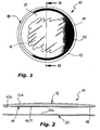
- a decorative member according to the invention is indicated 10 in its whole.
- the shape of the member 10 shown in the figures is circular, it could, obviously, be anyone.
- the emblem 10 comprises a first body 12 of a substantially rigid transparent plastic material, usually made of poly-metil-meth-acrylate (PMMA) or of polycarbonate (PC), typically formed as a result of a moulding process, for example of the injection type.
- PMMA poly-metil-meth-acrylate
- PC polycarbonate
- the body 12 has a front face 12a intended to face the outside, in the use, and therefore an observer, and a rear face 12b opposite to the face 12a.
- the front face 12a is smooth and preferably convex, while the rear face 12b is substantially flat, so that the body 12 has the general appearance and the function of a lens. Hovewer, the rear face 12b can be provided with slight hollow prints (not shown) to define a series of ornamental or graphical patterns.
- the plastic material used for making the body 12 incorporates a UV rays screening agent, in order to carry out a protective action towards aggressive action of solar radiation, for the layers below it.
- This screening agent may consist of a substance belonging to benzotriazol family.
- an effective UV rays screening action can be obtained by adding to the plastic material of the body 12 about 2.5% in weight of a concentrated masterbatch containing 2-(2H-benzotriazol-2-yl)-p-cresol.
- the plastic material of the body 12 is prepared, before the moulding step, by subjecting it to a dehumidification process in order to remove any possible trace of humidity from the material.
- the moulding step of the body 12 After the moulding step of the body 12, it undergoes again a dehumidification process, in order to remove any possible residual humidity.
- the rear face 12b of the body 12 may undergo a deep cleaning process by means of corona electrical discharge, or cold plasma or liquid CO 2 treatment, in order to remove possible dusts, impurities and/or traces of fat.
- an image 16 is formed on the rear face 12b of the body 12 by means of the known ink-jet printing technique.
- the image 16 is printed at a printing zone 14 the size of which is substantially smaller than the overall extension of the face 12b, in such a manner that a free perimetral edge 18 extends outside of the printing zone 14, which edge encircles all the zone 14.
- the image 16 may be also very complex, may have very fine details and can be made by an almost unlimited number of colors. Moreover, it can be modified or replaced in a very short time, which would be practically impossible if other usually known printing techniques should be used, such as conventional painting, tampography, serigraphy or hot printing.
- the ink of the image 16 is then dried and polymerized by means of a UV ray polymerization device known per se.
- a usually light bottom layer 17, typically white may be applied on the image 16 by means of ink-jet printing technique, always and only inside the printing zone 14.
- This bottom layer 17 constitutes a background for the image 16 and, at the same time, a coating having the function of a first protection for the image 16.
- the bottom layer 17 is preferably dried and polymerized by means of a UV ray polymerization device known per se.
- the deumidification step performed before printing the image 16 at the printing zone 14, has also the function of promoting adhesion both of the ink of the image 16 and of the possible bottom layer 17, on the rear face 12b.
- the surface of the printing zone 14 may be slightly rough.
- the mould used for printing the body 12 previously undergoes a sandblasting process, at the printing zone 14 only, in such a manner that the surface of the zone 14 of the body 12 is also correspondingly rough.
- a second body 20 is prepared, the plan shape of which corresponds to that of the body 12.
- the second body 12 is made by moulding, typically by injection moulding, a substantially rigid plastic material, such as poly-metil-meth-acrylate (PMMA), polycarbonate (PC) or ABS.
- PMMA poly-metil-meth-acrylate
- PC polycarbonate
- ABS poly-metil-meth-acrylate
- the plastic material of the second 20 is opaque and preferably has a dark color, for example black.
- the material of the body 20 undergoes preferably a dehumidification process before the moulding step, and the body 20, after having been moulded, can be conveniently be treated by a dehumidification process in order to eliminate any trace of humidity.
- the front surface 20a of the body 20, which is intended to be applied against the body 12, is subjected to a corona electrical discharge, or cold plasma, or liquid CO 2 cleaning process.
- the bodies 12 and 20 are then arranged side by side, in such a manner that the image 16, formed at the printing area 14 of the face 12b, is interposed between them.
- the bodies 12 and 20 When the bodies 12 and 20 are arranged side by side, they undergo a relatively high pressure, typically comprised in the range from about 0.3 to 0.5 N/mm2, in order to promote the following reciprocal connection, and for fully ejecting any air present between the printing zone 14 of the body 12 and the front surface 20a of the body 20.
- a relatively high pressure typically comprised in the range from about 0.3 to 0.5 N/mm2
- the bodies 12 and 20 are stably connected to each other by means of a peripheral welding, preferably carried out by laser welding, by making a welding seam 22 that extends along the free edge 18, and therefore on the outside of the printing zone 14 and, particularly, on the outside of the image 16 and of the possible bottom layer 17.
- a peripheral welding preferably carried out by laser welding
- the materials of the body 12 and of the body 20 interpenetrate by fusion and they make a kind of seal encircling the printing zone 14, so that the image 14 is enclosed in a chamber without any air that is sealingly closed with respect to the outer environment, in order to avoid any possible attack by atmospheric agents.
- the welding seam 22 obtained by using laser welding technique consists of a track having a width in the range from 1 to 4 mm, and a thickness that may vary from 0.1 to 0.4 mm, depending on parameters of the process and on the shape of the member 10.
- laser welding of the bodies 12 and 20 is preferably carried out by using a laser welding head arranged on the side of the front face 12b of the body 12, which laser head emits a laser beam focused at the peripheral surface of contact of the edges of the bodies 12 and 20.
- the decorative member 10 obtained in this manner undergoes a thermal stress relieving process in a furnace, for example for a time of about 6 hours at 70°C. In this manner, it will be able to stand wide thermal excursions, usually in the range from -30°C to +90°C, without suffering any appreciable deformation and therefore without deteriorations of the image 14.
- a modification of the invention is schematically shown in figure 5 , wherein the same numeral references of the previous modification have been used to indicate parts equal or similar to it. Constructive details of the bodies 12 and 20, and about realization of the image 16 as well as of the possible bottom layer 17, are the same of the previous modification, and therefore they will not be described again.
- connection of the bodies 12 and 20 is obtained by means of glueing, as a result of the application of a strip 24 of adhesive material on the rear face 12b of the body 12, on the outside of the zone 14 so as to encircle it, or on a corresponding portion of the front surface 20a of the body 20.
- a relatively high pressure is applied to the bodies 12 and 20 arranged side by side, the amount of which is analogous to that already described with reference to the previous modification, so as to get at the same time connection of the two bodies and ejection of any air from the chamber in which the image 16 will be enclosed.
- the member 10 obtained in this manner can be inserted in a frame (not shown), for example of chromium plated plastic material, with the aim of hiding the edge of the decorative member in which the welding seam 18 or the strip 24 of adhesive material, respectively, is present.
Landscapes
- Engineering & Computer Science (AREA)
- Mechanical Engineering (AREA)
- Vehicle Interior And Exterior Ornaments, Soundproofing, And Insulation (AREA)
- Vehicle Waterproofing, Decoration, And Sanitation Devices (AREA)
- Ink Jet (AREA)
Claims (18)
- Élément décoratif, en particulier destiné à être utilisé comme un emblème pour un véhicule à moteur, comprenant :- un premier corps (12) en une matière plastique transparent ayant une face avant (12a) et une face arrière sensiblement plate (12b),- une image (16) formée par impression à jet d'encre dans une zone d'impression (14) de la face arrière (12b), et- un deuxième corps généralement plat (20) en une matière plastique sensiblement rigide appliquée sur la face arrière (12b) du premier corps (12)caractérisé en ce que la dimension de la zone d'impression (14) du premier corps (12) est sensiblement plus petite que sa face arrière (12b), et en ce que le premier corps (12) et le deuxième corps (20) sont reliés l'un à l'autre par une bande de liaison (22, 24) qui entoure la zone d'impression (14), laquelle bande forme une étanchéité, de telle sorte que l'image (16) est enfermée dans une chambre fermée de façon étanche par rapport à l'environnement externe.
- Élément selon la revendication 1, caractérisé en ce que la face avant (12a) du premier corps (12) est convexe, de sorte que le premier corps (12) est en forme de lentille.
- Élément selon la revendication 1 ou la revendication 2, caractérisé en ce que le deuxième corps (20) est un corps opaque, de préférence ayant une couleur sombre ou noire.
- Élément selon l'une quelconque des revendications 1 à 3, caractérisé en ce qu'une couche de peinture blanche (17) est appliquée sur le côté de l'image (16) situé à l'opposée du premier corps (12) et à l'intérieur de ladite zone de l'impression (14).
- Élément selon l'une quelconque des revendications 1 à 4, caractérisé en ce que ladite bande de raccordement est constituée par une ligne de soudure (22).
- Élément selon l'une quelconque des revendications 1 à 4, caractérisé en ce que ladite bande de raccordement est constituée par une bande de matériau adhésif (24).
- Procédé de fabrication d'un élément décoratif, en particulier destiné à être utilisé comme un emblème pour un véhicule à moteur, comprenant les étapes consistant à :- fabriquer un premier corps (12) en une matière plastique transparente ayant une face avant (12a) et une face arrière sensiblement plate (12b), ainsi qu'un deuxième corps (20) généralement plat en une matière sensiblement rigide,- former une image (16) au moyen d'une impression à jet d'encre dans une zone d'impression (14) de la face arrière (12b) du premier corps (12), et,- relier le premier corps (12) et le deuxième corps (20) l'un à l'autre, ladite image (16) étant interposée entre eux,caractérisé en ce que la zone d'impression (14) s'étend sur une zone plus petite que l'ensemble de la face arrière (12b) du premier corps (12), de sorte qu'un bord (18) du premier corps (12) est dépourvu de l'encre de l'image (16), et en ce que l'étape de connexion du premier corps (12) et du deuxième corps (20) est réalisée le long d'une zone en forme de bande (22 ; 24) s'étendant au niveau dudit bord libre (18), afin qu'un joint étanche entourant la zone d'impression (14) soit défini, de telle sorte que l'image (14) soit enfermée dans une chambre fermée de façon étanche par rapport à l'environnement externe.
- Procédé selon la revendication 7, caractérisé en ce qu'il comprend l'étape consistant à appliquer une couche de peinture blanche (17) sur l'image (16) et/ou sur la zone d'impression (14).
- Procédé selon la revendication 8, caractérisé en ce que ladite couche de peinture blanche (17) est réalisée par impression à jet d'encre.
- Procédé selon la revendication 7 ou la revendication 8, caractérisé en ce que le raccordement du premier corps (12) et du deuxième corps (20) comprend l'étape consistant à souder lesdits corps (12, 20) selon une ligne de soudure (18) sur l'extérieur de ladite zone d'impression (14).
- Procédé selon la revendication 10, caractérisé en ce que le deuxième corps (20) est un corps opaque, de préférence ayant une couleur sombre ou noire, et en ce que ladite étape de soudage est effectuée par une tête de soudage laser travaillant sur le côté de la face avant (12a) du premier corps (12).
- Procédé selon l'une quelconque des revendications 7 à 9, caractérisé en ce que la connexion desdits corps (12, 20) comprend l'étape consistant à interposer une bande de matériau adhésif (24) entre eux, à l'extérieur de ladite zone d'impression (14).
- Procédé selon la revendication 7 ou la revendication 8, caractérisé en ce que le premier et le deuxième corps (12, 20) disposés côte à côte sont soumis à une pression élevée, lors de l'étape de connexion de celui-ci, afin de favoriser leur connexion et pour éjecter l'air de la zone de contact mutuelle.
- Procédé selon l'une quelconque des revendications 7 à 13, caractérisé en ce que ledit premier corps (12) est formé par une étape de moulage, et en ce que le moule utilisé pour former le premier corps (12) est soumis à un processus de sablage uniquement au niveau de la zone d'impression (14) de sa face arrière (12b), de telle manière que la surface de la zone d'impression (14) est légèrement rugueuse afin d'améliorer l'adhérence de l'encre de ladite image (16) et/ou de ladite couche de peinture blanche (17).
- Procédé selon l'une quelconque des revendications 7 à 14, caractérisé en ce que la matière plastique utilisée pour la fabrication du premier et du deuxième corps (12, 20) est soumise à un processus de déshumidification, et en ce que le premier et le deuxième corps (12, 20) sont soumis à un processus de déshumidification avant la formation de ladite image (16).
- Procédé selon l'une quelconque des revendications 7 à 15, caractérisé en ce que un agent de filtrage de rayons UV est incorporé dans la matière plastique utilisée pour la fabrication du premier corps (12), afin que ledit agent de filtrage ait une action de protection pour l'encre de ladite l'image (16) par rapport au rayonnement solaire.
- Procédé selon l'une quelconque des revendications 7 à 16, caractérisé en ce que la surface arrière (12b) du premier corps (12) de même que la surface du corps (20) destinée à être en contact avec le premier corps (12), sont soumises à un processus de nettoyage au moyen d'effet corona, de plasma froid ou de CO2 liquide.
- Procédé selon l'une quelconque des revendications 7 à 17, caractérisé en ce que l'ensemble de l'élément décoratif (10) est soumis à un processus thermique de libération de contraintes.
Applications Claiming Priority (1)
| Application Number | Priority Date | Filing Date | Title |
|---|---|---|---|
| ITTO2009A000912A IT1396785B1 (it) | 2009-11-25 | 2009-11-25 | Elemento decorativo, particolarmente per l'impiego come emblema su di un autoveicolo, e relativo procedimento di fabbricazione. |
Publications (2)
| Publication Number | Publication Date |
|---|---|
| EP2327588A1 EP2327588A1 (fr) | 2011-06-01 |
| EP2327588B1 true EP2327588B1 (fr) | 2012-10-24 |
Family
ID=42270554
Family Applications (1)
| Application Number | Title | Priority Date | Filing Date |
|---|---|---|---|
| EP10014856A Not-in-force EP2327588B1 (fr) | 2009-11-25 | 2010-11-23 | Elément décoratif, en particulier pour l'utilisation comme emblème de véhicule automobile et méthode de production |
Country Status (4)
| Country | Link |
|---|---|
| US (1) | US20110123731A1 (fr) |
| EP (1) | EP2327588B1 (fr) |
| BR (1) | BRPI1004191A2 (fr) |
| IT (1) | IT1396785B1 (fr) |
Cited By (2)
| Publication number | Priority date | Publication date | Assignee | Title |
|---|---|---|---|---|
| DE102016002831A1 (de) | 2016-03-09 | 2017-09-14 | Linden Gmbh | Metallisch glänzendes Teil |
| DE102016012422A1 (de) | 2016-10-17 | 2018-04-19 | Linden Gmbh | Metallisch glänzendes Teil |
Families Citing this family (6)
| Publication number | Priority date | Publication date | Assignee | Title |
|---|---|---|---|---|
| ITTO20110501A1 (it) * | 2011-06-08 | 2012-12-09 | Zanini Holding S P A | Elemento decorativo, particolarmente utilizzabile come emblema per un autoveicolo. |
| US9784427B2 (en) * | 2015-01-09 | 2017-10-10 | GM Global Technology Operations LLC | Backlit illuminated device with lighting through decorative plated surfaces |
| DE102015217744A1 (de) * | 2015-09-16 | 2017-03-16 | Nanogate PD Systems GmbH | Radom |
| DE202016004277U1 (de) * | 2016-07-09 | 2016-09-01 | Franz Rothbrust | Kombination zwischen einem Druck und einem transparenten Relief |
| JP7101634B2 (ja) * | 2019-03-29 | 2022-07-15 | 本田技研工業株式会社 | 樹脂成形品 |
| CN112233581A (zh) * | 2019-07-15 | 2021-01-15 | 宁波金雨科技实业有限公司 | 实现立体浮雕效果的加工方法及利用该加工方法的化妆瓶 |
Family Cites Families (22)
| Publication number | Priority date | Publication date | Assignee | Title |
|---|---|---|---|---|
| US4244762A (en) * | 1979-04-10 | 1981-01-13 | The Holson Company | Heat sealed photo album page and method of making same |
| US4661189A (en) * | 1984-11-14 | 1987-04-28 | Janus Label Corporation | Method for manufacturing discrete elements |
| US5156698A (en) * | 1990-08-10 | 1992-10-20 | Dean Roberts | Integral packaging for puzzle postcard and other products and method of making |
| US5580410A (en) * | 1994-12-14 | 1996-12-03 | Delta Technology, Inc. | Pre-conditioning a substrate for accelerated dispersed dye sublimation printing |
| DE29512551U1 (de) * | 1995-08-03 | 1995-12-14 | TRW Repa GmbH, 73551 Alfdorf | Abdeckung für ein Gassack-Rückhaltesystem in Fahrzeugen |
| ATE297262T1 (de) * | 1996-01-11 | 2005-06-15 | Gregory Edye Ross | Perimeter beschichtungsverfahren |
| JP3296964B2 (ja) * | 1996-03-04 | 2002-07-02 | 太平洋工業株式会社 | 車両外装用樹脂製エンブレム |
| US6638388B2 (en) * | 2000-08-11 | 2003-10-28 | Canon Kabushiki Kaisha | Laminating film and laminating method using it |
| WO2002040291A2 (fr) * | 2000-11-02 | 2002-05-23 | Taylor Corporation | Carte lenticulaire et processus de fabrication |
| US6701652B1 (en) * | 2001-10-22 | 2004-03-09 | Serigraph, Inc. | Molded emblem with encapsulated embossed 3-D graphics |
| US7611602B2 (en) * | 2001-12-13 | 2009-11-03 | Urban Mapping, Llc | Method of producing maps and other objects configured for presentation of spatially-related layers of data |
| ATE297319T1 (de) * | 2002-03-08 | 2005-06-15 | 3M Innovative Properties Co | Kraftfahrzeugemblem sowie verfahren zu seiner herstellung |
| US7040227B1 (en) * | 2002-10-02 | 2006-05-09 | E Innovations, Inc. | Stamping devices and methods |
| US6974207B2 (en) * | 2002-11-19 | 2005-12-13 | Lexmark International, Inc. | Laser welding methods and structures and control therefor including welded inkjet printheads |
| AT500617B1 (de) * | 2004-07-26 | 2006-02-15 | Fischer Gmbh | Verfahren zum dekorieren von sportgeräten sowie folie zur durchführung des verfahrens |
| US20080271351A1 (en) * | 2005-06-07 | 2008-11-06 | Jay Crawford | Lenticular License Plate and Method |
| CA2568736C (fr) | 2006-11-23 | 2010-01-26 | Henry Sawatsky | Decoration d'articles et de marchandises |
| ITTO20060845A1 (it) * | 2006-11-29 | 2008-05-30 | Zanini S P A | Procedimento per la fabbricazione di un emblema o di un simile elemento decorativo, particolarmente applicabile su di un autoveicolo. |
| US20090011192A1 (en) * | 2007-07-03 | 2009-01-08 | John Tomczyk | Method, system, and apparatus for producing dimensional image articles utilizing a cushioning assembly |
| JP4497218B2 (ja) * | 2008-03-06 | 2010-07-07 | セイコーエプソン株式会社 | 接合方法および接合体 |
| US8331031B2 (en) * | 2008-09-18 | 2012-12-11 | Travel Tags, Inc. | Thin film high definition dimensional image display device and methods of making same |
| JP5293325B2 (ja) * | 2009-03-25 | 2013-09-18 | セイコーエプソン株式会社 | 記録装置及び搬送方法 |
-
2009
- 2009-11-25 IT ITTO2009A000912A patent/IT1396785B1/it active
-
2010
- 2010-11-23 EP EP10014856A patent/EP2327588B1/fr not_active Not-in-force
- 2010-11-23 US US12/953,079 patent/US20110123731A1/en not_active Abandoned
- 2010-11-25 BR BRPI1004191-5A patent/BRPI1004191A2/pt not_active Application Discontinuation
Cited By (2)
| Publication number | Priority date | Publication date | Assignee | Title |
|---|---|---|---|---|
| DE102016002831A1 (de) | 2016-03-09 | 2017-09-14 | Linden Gmbh | Metallisch glänzendes Teil |
| DE102016012422A1 (de) | 2016-10-17 | 2018-04-19 | Linden Gmbh | Metallisch glänzendes Teil |
Also Published As
| Publication number | Publication date |
|---|---|
| IT1396785B1 (it) | 2012-12-14 |
| BRPI1004191A2 (pt) | 2013-03-05 |
| ITTO20090912A1 (it) | 2011-05-26 |
| EP2327588A1 (fr) | 2011-06-01 |
| US20110123731A1 (en) | 2011-05-26 |
Similar Documents
| Publication | Publication Date | Title |
|---|---|---|
| EP2327588A1 (fr) | Elément décoratif, en particulier pour l'utilisation comme emblème de véhicule automobile et méthode de production | |
| US20110088827A1 (en) | Method for manufacturing a decorative member, particularly intended to be used as an emblem on a motor vehicle | |
| JP7097857B2 (ja) | プラスチック製の車両付設部材を製造する方法 | |
| KR102207465B1 (ko) | 플라스틱 차량 부가 부품 제조 방법 | |
| EP3047476B1 (fr) | Étiquette d'ornement d'une bouteille, bouteille et procédé de fabrication d'une telle étiquette | |
| EP1927480B1 (fr) | Procédé de fabrication d'un emblème transparent ou élément décoratif similaire | |
| EP1342589B1 (fr) | Emblème de véhicules à moteur et procédé pour sa fabrication | |
| US20090208756A1 (en) | Housing for electronic equipment and manufacturing method thereof | |
| US11628605B2 (en) | Method for producing a shaped plastic part having a decorated surface | |
| CN101903184A (zh) | 用于制造装饰成型体的方法 | |
| JP5296059B2 (ja) | 優れた立体感を有する転写シート | |
| CN101616822A (zh) | 具有彩色和银色光泽的表面的徽章 | |
| EP2683537B1 (fr) | Film thermoplastique décoré et ses procédés de fabrication | |
| CN114953689A (zh) | 一种汽车内饰件精确透光的生产工艺 | |
| JP2006255894A (ja) | ヘアライン調加飾シート | |
| JP2011079161A (ja) | 装飾用部品及び装飾用部品の製造方法 | |
| JP6809886B2 (ja) | レーダカバー及びレーダカバーの製造方法 | |
| KR100750791B1 (ko) | 평판형 프린터를 이용한 코팅 안경 및 이의 제조 방법. | |
| US10083634B2 (en) | In-mold labeled article and method | |
| JP2018051818A (ja) | 蒸着エンブレムおよびその製造方法 | |
| KR20140040922A (ko) | 안경테 및 이의 제조방법 | |
| NZ616261B2 (en) | Decorated thermoplastic film and methods for making the same | |
| JPH02137985A (ja) | 外装部品外表面の絵付方法 | |
| HK1194035A (en) | Decorated thermoplastic film and methods for making the same | |
| JPS629986A (ja) | 透明体複曲面への連続パタ−ン塗膜形成方法 |
Legal Events
| Date | Code | Title | Description |
|---|---|---|---|
| PUAI | Public reference made under article 153(3) epc to a published international application that has entered the european phase |
Free format text: ORIGINAL CODE: 0009012 |
|
| AK | Designated contracting states |
Kind code of ref document: A1 Designated state(s): AL AT BE BG CH CY CZ DE DK EE ES FI FR GB GR HR HU IE IS IT LI LT LU LV MC MK MT NL NO PL PT RO RS SE SI SK SM TR |
|
| AX | Request for extension of the european patent |
Extension state: BA ME |
|
| 17P | Request for examination filed |
Effective date: 20111129 |
|
| GRAP | Despatch of communication of intention to grant a patent |
Free format text: ORIGINAL CODE: EPIDOSNIGR1 |
|
| GRAS | Grant fee paid |
Free format text: ORIGINAL CODE: EPIDOSNIGR3 |
|
| GRAA | (expected) grant |
Free format text: ORIGINAL CODE: 0009210 |
|
| RIN1 | Information on inventor provided before grant (corrected) |
Inventor name: FRANZINO, MARIO Inventor name: ZANINI, PAOLO |
|
| AK | Designated contracting states |
Kind code of ref document: B1 Designated state(s): AL AT BE BG CH CY CZ DE DK EE ES FI FR GB GR HR HU IE IS IT LI LT LU LV MC MK MT NL NO PL PT RO RS SE SI SK SM TR |
|
| REG | Reference to a national code |
Ref country code: GB Ref legal event code: FG4D |
|
| REG | Reference to a national code |
Ref country code: CH Ref legal event code: EP |
|
| REG | Reference to a national code |
Ref country code: AT Ref legal event code: REF Ref document number: 580733 Country of ref document: AT Kind code of ref document: T Effective date: 20121115 |
|
| REG | Reference to a national code |
Ref country code: IE Ref legal event code: FG4D |
|
| REG | Reference to a national code |
Ref country code: DE Ref legal event code: R096 Ref document number: 602010003270 Country of ref document: DE Effective date: 20121220 |
|
| REG | Reference to a national code |
Ref country code: AT Ref legal event code: MK05 Ref document number: 580733 Country of ref document: AT Kind code of ref document: T Effective date: 20121024 |
|
| REG | Reference to a national code |
Ref country code: NL Ref legal event code: VDEP Effective date: 20121024 |
|
| PG25 | Lapsed in a contracting state [announced via postgrant information from national office to epo] |
Ref country code: IS Free format text: LAPSE BECAUSE OF FAILURE TO SUBMIT A TRANSLATION OF THE DESCRIPTION OR TO PAY THE FEE WITHIN THE PRESCRIBED TIME-LIMIT Effective date: 20130224 Ref country code: SE Free format text: LAPSE BECAUSE OF FAILURE TO SUBMIT A TRANSLATION OF THE DESCRIPTION OR TO PAY THE FEE WITHIN THE PRESCRIBED TIME-LIMIT Effective date: 20121024 Ref country code: HR Free format text: LAPSE BECAUSE OF FAILURE TO SUBMIT A TRANSLATION OF THE DESCRIPTION OR TO PAY THE FEE WITHIN THE PRESCRIBED TIME-LIMIT Effective date: 20121024 Ref country code: NO Free format text: LAPSE BECAUSE OF FAILURE TO SUBMIT A TRANSLATION OF THE DESCRIPTION OR TO PAY THE FEE WITHIN THE PRESCRIBED TIME-LIMIT Effective date: 20130124 Ref country code: ES Free format text: LAPSE BECAUSE OF FAILURE TO SUBMIT A TRANSLATION OF THE DESCRIPTION OR TO PAY THE FEE WITHIN THE PRESCRIBED TIME-LIMIT Effective date: 20130204 Ref country code: NL Free format text: LAPSE BECAUSE OF FAILURE TO SUBMIT A TRANSLATION OF THE DESCRIPTION OR TO PAY THE FEE WITHIN THE PRESCRIBED TIME-LIMIT Effective date: 20121024 Ref country code: FI Free format text: LAPSE BECAUSE OF FAILURE TO SUBMIT A TRANSLATION OF THE DESCRIPTION OR TO PAY THE FEE WITHIN THE PRESCRIBED TIME-LIMIT Effective date: 20121024 |
|
| PG25 | Lapsed in a contracting state [announced via postgrant information from national office to epo] |
Ref country code: PT Free format text: LAPSE BECAUSE OF FAILURE TO SUBMIT A TRANSLATION OF THE DESCRIPTION OR TO PAY THE FEE WITHIN THE PRESCRIBED TIME-LIMIT Effective date: 20130225 Ref country code: SI Free format text: LAPSE BECAUSE OF FAILURE TO SUBMIT A TRANSLATION OF THE DESCRIPTION OR TO PAY THE FEE WITHIN THE PRESCRIBED TIME-LIMIT Effective date: 20121024 Ref country code: BE Free format text: LAPSE BECAUSE OF FAILURE TO SUBMIT A TRANSLATION OF THE DESCRIPTION OR TO PAY THE FEE WITHIN THE PRESCRIBED TIME-LIMIT Effective date: 20121024 Ref country code: PL Free format text: LAPSE BECAUSE OF FAILURE TO SUBMIT A TRANSLATION OF THE DESCRIPTION OR TO PAY THE FEE WITHIN THE PRESCRIBED TIME-LIMIT Effective date: 20121024 Ref country code: LV Free format text: LAPSE BECAUSE OF FAILURE TO SUBMIT A TRANSLATION OF THE DESCRIPTION OR TO PAY THE FEE WITHIN THE PRESCRIBED TIME-LIMIT Effective date: 20121024 Ref country code: GR Free format text: LAPSE BECAUSE OF FAILURE TO SUBMIT A TRANSLATION OF THE DESCRIPTION OR TO PAY THE FEE WITHIN THE PRESCRIBED TIME-LIMIT Effective date: 20130125 |
|
| PG25 | Lapsed in a contracting state [announced via postgrant information from national office to epo] |
Ref country code: AT Free format text: LAPSE BECAUSE OF FAILURE TO SUBMIT A TRANSLATION OF THE DESCRIPTION OR TO PAY THE FEE WITHIN THE PRESCRIBED TIME-LIMIT Effective date: 20121024 |
|
| PG25 | Lapsed in a contracting state [announced via postgrant information from national office to epo] |
Ref country code: SK Free format text: LAPSE BECAUSE OF FAILURE TO SUBMIT A TRANSLATION OF THE DESCRIPTION OR TO PAY THE FEE WITHIN THE PRESCRIBED TIME-LIMIT Effective date: 20121024 Ref country code: RS Free format text: LAPSE BECAUSE OF FAILURE TO SUBMIT A TRANSLATION OF THE DESCRIPTION OR TO PAY THE FEE WITHIN THE PRESCRIBED TIME-LIMIT Effective date: 20121024 Ref country code: EE Free format text: LAPSE BECAUSE OF FAILURE TO SUBMIT A TRANSLATION OF THE DESCRIPTION OR TO PAY THE FEE WITHIN THE PRESCRIBED TIME-LIMIT Effective date: 20121024 Ref country code: DK Free format text: LAPSE BECAUSE OF FAILURE TO SUBMIT A TRANSLATION OF THE DESCRIPTION OR TO PAY THE FEE WITHIN THE PRESCRIBED TIME-LIMIT Effective date: 20121024 Ref country code: BG Free format text: LAPSE BECAUSE OF FAILURE TO SUBMIT A TRANSLATION OF THE DESCRIPTION OR TO PAY THE FEE WITHIN THE PRESCRIBED TIME-LIMIT Effective date: 20130124 Ref country code: CZ Free format text: LAPSE BECAUSE OF FAILURE TO SUBMIT A TRANSLATION OF THE DESCRIPTION OR TO PAY THE FEE WITHIN THE PRESCRIBED TIME-LIMIT Effective date: 20121024 |
|
| REG | Reference to a national code |
Ref country code: IE Ref legal event code: MM4A |
|
| PG25 | Lapsed in a contracting state [announced via postgrant information from national office to epo] |
Ref country code: RO Free format text: LAPSE BECAUSE OF FAILURE TO SUBMIT A TRANSLATION OF THE DESCRIPTION OR TO PAY THE FEE WITHIN THE PRESCRIBED TIME-LIMIT Effective date: 20121024 |
|
| PLBE | No opposition filed within time limit |
Free format text: ORIGINAL CODE: 0009261 |
|
| STAA | Information on the status of an ep patent application or granted ep patent |
Free format text: STATUS: NO OPPOSITION FILED WITHIN TIME LIMIT |
|
| REG | Reference to a national code |
Ref country code: FR Ref legal event code: ST Effective date: 20130731 |
|
| 26N | No opposition filed |
Effective date: 20130725 |
|
| PG25 | Lapsed in a contracting state [announced via postgrant information from national office to epo] |
Ref country code: IE Free format text: LAPSE BECAUSE OF NON-PAYMENT OF DUE FEES Effective date: 20121123 |
|
| REG | Reference to a national code |
Ref country code: DE Ref legal event code: R097 Ref document number: 602010003270 Country of ref document: DE Effective date: 20130725 |
|
| PG25 | Lapsed in a contracting state [announced via postgrant information from national office to epo] |
Ref country code: FR Free format text: LAPSE BECAUSE OF NON-PAYMENT OF DUE FEES Effective date: 20121226 Ref country code: MT Free format text: LAPSE BECAUSE OF FAILURE TO SUBMIT A TRANSLATION OF THE DESCRIPTION OR TO PAY THE FEE WITHIN THE PRESCRIBED TIME-LIMIT Effective date: 20121024 Ref country code: CY Free format text: LAPSE BECAUSE OF FAILURE TO SUBMIT A TRANSLATION OF THE DESCRIPTION OR TO PAY THE FEE WITHIN THE PRESCRIBED TIME-LIMIT Effective date: 20121024 Ref country code: AL Free format text: LAPSE BECAUSE OF FAILURE TO SUBMIT A TRANSLATION OF THE DESCRIPTION OR TO PAY THE FEE WITHIN THE PRESCRIBED TIME-LIMIT Effective date: 20121024 |
|
| PG25 | Lapsed in a contracting state [announced via postgrant information from national office to epo] |
Ref country code: MC Free format text: LAPSE BECAUSE OF NON-PAYMENT OF DUE FEES Effective date: 20121130 Ref country code: TR Free format text: LAPSE BECAUSE OF FAILURE TO SUBMIT A TRANSLATION OF THE DESCRIPTION OR TO PAY THE FEE WITHIN THE PRESCRIBED TIME-LIMIT Effective date: 20121024 |
|
| PG25 | Lapsed in a contracting state [announced via postgrant information from national office to epo] |
Ref country code: SM Free format text: LAPSE BECAUSE OF FAILURE TO SUBMIT A TRANSLATION OF THE DESCRIPTION OR TO PAY THE FEE WITHIN THE PRESCRIBED TIME-LIMIT Effective date: 20121024 Ref country code: LU Free format text: LAPSE BECAUSE OF NON-PAYMENT OF DUE FEES Effective date: 20121123 |
|
| PG25 | Lapsed in a contracting state [announced via postgrant information from national office to epo] |
Ref country code: HU Free format text: LAPSE BECAUSE OF FAILURE TO SUBMIT A TRANSLATION OF THE DESCRIPTION OR TO PAY THE FEE WITHIN THE PRESCRIBED TIME-LIMIT Effective date: 20101123 Ref country code: LT Free format text: LAPSE BECAUSE OF FAILURE TO SUBMIT A TRANSLATION OF THE DESCRIPTION OR TO PAY THE FEE WITHIN THE PRESCRIBED TIME-LIMIT Effective date: 20121024 |
|
| REG | Reference to a national code |
Ref country code: CH Ref legal event code: PL |
|
| GBPC | Gb: european patent ceased through non-payment of renewal fee |
Effective date: 20141123 |
|
| PG25 | Lapsed in a contracting state [announced via postgrant information from national office to epo] |
Ref country code: LI Free format text: LAPSE BECAUSE OF NON-PAYMENT OF DUE FEES Effective date: 20141130 Ref country code: CH Free format text: LAPSE BECAUSE OF NON-PAYMENT OF DUE FEES Effective date: 20141130 Ref country code: MK Free format text: LAPSE BECAUSE OF FAILURE TO SUBMIT A TRANSLATION OF THE DESCRIPTION OR TO PAY THE FEE WITHIN THE PRESCRIBED TIME-LIMIT Effective date: 20121024 |
|
| PG25 | Lapsed in a contracting state [announced via postgrant information from national office to epo] |
Ref country code: GB Free format text: LAPSE BECAUSE OF NON-PAYMENT OF DUE FEES Effective date: 20141123 |
|
| REG | Reference to a national code |
Ref country code: DE Ref legal event code: R082 Ref document number: 602010003270 Country of ref document: DE Representative=s name: GUSTORF, GERHARD, DIPL.-ING., DE Ref country code: DE Ref legal event code: R081 Ref document number: 602010003270 Country of ref document: DE Owner name: ZANINI AUTO GRUP, S.A., ES Free format text: FORMER OWNER: ZANINI HOLDING S.P.A., PARUZZARO, IT |
|
| PGFP | Annual fee paid to national office [announced via postgrant information from national office to epo] |
Ref country code: DE Payment date: 20171124 Year of fee payment: 8 |
|
| PGFP | Annual fee paid to national office [announced via postgrant information from national office to epo] |
Ref country code: IT Payment date: 20171122 Year of fee payment: 8 |
|
| REG | Reference to a national code |
Ref country code: DE Ref legal event code: R119 Ref document number: 602010003270 Country of ref document: DE |
|
| PG25 | Lapsed in a contracting state [announced via postgrant information from national office to epo] |
Ref country code: DE Free format text: LAPSE BECAUSE OF NON-PAYMENT OF DUE FEES Effective date: 20190601 Ref country code: IT Free format text: LAPSE BECAUSE OF NON-PAYMENT OF DUE FEES Effective date: 20181123 |