EP2657401A1 - Plaque de montage - Google Patents
Plaque de montage Download PDFInfo
- Publication number
- EP2657401A1 EP2657401A1 EP13001400.4A EP13001400A EP2657401A1 EP 2657401 A1 EP2657401 A1 EP 2657401A1 EP 13001400 A EP13001400 A EP 13001400A EP 2657401 A1 EP2657401 A1 EP 2657401A1
- Authority
- EP
- European Patent Office
- Prior art keywords
- wall
- laying plate
- receiving
- groove
- plate according
- Prior art date
- Legal status (The legal status is an assumption and is not a legal conclusion. Google has not performed a legal analysis and makes no representation as to the accuracy of the status listed.)
- Granted
Links
Images



Classifications
-
- E—FIXED CONSTRUCTIONS
- E01—CONSTRUCTION OF ROADS, RAILWAYS, OR BRIDGES
- E01C—CONSTRUCTION OF, OR SURFACES FOR, ROADS, SPORTS GROUNDS, OR THE LIKE; MACHINES OR AUXILIARY TOOLS FOR CONSTRUCTION OR REPAIR
- E01C5/00—Pavings made of prefabricated single units
- E01C5/005—Individual couplings or spacer elements for joining the prefabricated units
-
- E—FIXED CONSTRUCTIONS
- E01—CONSTRUCTION OF ROADS, RAILWAYS, OR BRIDGES
- E01C—CONSTRUCTION OF, OR SURFACES FOR, ROADS, SPORTS GROUNDS, OR THE LIKE; MACHINES OR AUXILIARY TOOLS FOR CONSTRUCTION OR REPAIR
- E01C11/00—Details of pavings
- E01C11/22—Gutters; Kerbs ; Surface drainage of streets, roads or like traffic areas
- E01C11/224—Surface drainage of streets
- E01C11/225—Paving specially adapted for through-the-surfacing drainage, e.g. perforated, porous; Preformed paving elements comprising, or adapted to form, passageways for carrying off drainage
-
- E—FIXED CONSTRUCTIONS
- E01—CONSTRUCTION OF ROADS, RAILWAYS, OR BRIDGES
- E01C—CONSTRUCTION OF, OR SURFACES FOR, ROADS, SPORTS GROUNDS, OR THE LIKE; MACHINES OR AUXILIARY TOOLS FOR CONSTRUCTION OR REPAIR
- E01C5/00—Pavings made of prefabricated single units
- E01C5/20—Pavings made of prefabricated single units made of units of plastics, e.g. concrete with plastics, linoleum
-
- E—FIXED CONSTRUCTIONS
- E01—CONSTRUCTION OF ROADS, RAILWAYS, OR BRIDGES
- E01C—CONSTRUCTION OF, OR SURFACES FOR, ROADS, SPORTS GROUNDS, OR THE LIKE; MACHINES OR AUXILIARY TOOLS FOR CONSTRUCTION OR REPAIR
- E01C9/00—Special pavings; Pavings for special parts of roads or airfields
- E01C9/08—Temporary pavings
- E01C9/086—Temporary pavings made of concrete, wood, bitumen, rubber or synthetic material or a combination thereof
-
- E—FIXED CONSTRUCTIONS
- E01—CONSTRUCTION OF ROADS, RAILWAYS, OR BRIDGES
- E01C—CONSTRUCTION OF, OR SURFACES FOR, ROADS, SPORTS GROUNDS, OR THE LIKE; MACHINES OR AUXILIARY TOOLS FOR CONSTRUCTION OR REPAIR
- E01C11/00—Details of pavings
- E01C11/24—Methods or arrangements for preventing slipperiness or protecting against influences of the weather
-
- E—FIXED CONSTRUCTIONS
- E01—CONSTRUCTION OF ROADS, RAILWAYS, OR BRIDGES
- E01C—CONSTRUCTION OF, OR SURFACES FOR, ROADS, SPORTS GROUNDS, OR THE LIKE; MACHINES OR AUXILIARY TOOLS FOR CONSTRUCTION OR REPAIR
- E01C2201/00—Paving elements
- E01C2201/12—Paving elements vertically interlocking
Definitions
- the invention relates to a laying plate having a base body with outer walls, which have at least one male element and at least one receiving area with an insertion opening for the male element as a connecting device.
- Such a laying plate is through the EP 0 621 373 A2 known.
- the male member is formed as a hook projection with an upwardly open hook profile.
- a ⁇ senvorsprung is formed in the region of the insertion opening, which is under attacked by the hook profile in the closed state and engaged behind.
- the known installation plate can be disadvantageously installed only on a reasonably level surface, as an uneven floor leads to a sagging of the installation plates of the known floor covering and thus disadvantageously to an unintentional release of the plates.
- Another installation plate is through the DE 20 2010 005 276 U1 known.
- the feedthroughs on the inside of the outer wall are assigned undercut steps, via which the hook parts firmly engage when connecting two laying plates.
- the known installation plate can be disadvantageously installed only on a reasonably level surface and by the plurality of male elements per outer wall results in a fairly rigid connection between two installation panels. Furthermore, the joining of two installation plates is not easy due to the large number of insertion elements.
- the object of the invention is thus seen to further develop the installation plate of the type mentioned above so that the installation plate ensures great mechanical flexibility with low installation costs, so that the installation plates can be laid in a simple and fast way on an uneven floor.
- a protruding from the outer wall receiving element is provided with a parallel to the outer wall and upwardly open groove with a bevelled side wall, in which in the closed State, the male member comes into abutment, wherein the male member is adapted to the shape of the groove and the male member has a support surface on its upper side, which rests in the closed state on an inner surface of the underside of the outer wall in the region of the insertion.
- a first installation plate is first placed on the floor. Then, a second installation plate is inserted from above at an oblique angle of for example 45 ° with the male member in the receiving area of the first installation plate. As soon as the corresponding outer walls of the first laying plate and the second laying plate bear, the second laying plate is dropped. Due to the falling movement, the male member engages both completely in the insertion opening and in the groove of the receiving element and forms a positive connection. To open the connection, the second laying plate is lifted upwards to an oblique angle of, for example, again 45 ° and pulled away, so that the male element of the second laying plate leaves the receiving area of the first laying plate.
- the installation effort is very low, since only one receiving area or a male element is provided on an outer wall, which must be merged for connecting. Since only one connection region per outer side is provided, individual installation plates according to the invention can be mounted to form a larger laying unit, which has a high mechanical flexibility, so that even uneven outdoor surfaces can be covered with very little assembly and disassembly effort.
- the installation panels can be used in particular for an event floor, an irrigation system or a lawn grid.
- the male member has a support surface on its upper side, which in the closed state on an inner surface of the underside of the outer wall in the region of the insertion is applied. Due to the support surface, the male element is held in the insertion opening during deflection, wherein the male element is practically fixed in this deflection between the support surface on the one hand and the diagonally opposite base of the groove, so that a release is avoided.
- the insertion of the tapered side wall of the groove is arranged opposite.
- an embodiment of the invention provides that the bevelled side wall of the groove merges with a rounding into a base surface of the groove.
- the insertion element is designed in the form of an elongated web which protrudes from the outer wall. Such a web can be formed in particular in plastic moldings in a simple manner.
- a development of the invention provides that in the receiving element and in the Einissueelement each have an opening for receiving a rivet for fixing two installation plates is provided.
- the rivet should be designed so that it can either be very difficult or can only be removed by destruction.
- a further embodiment of the invention therefore provides that the rivet has an upper head area and a lower head area and a central area with a plurality of conical areas.
- the lower head portion is formed to be larger in diameter than the corresponding opening in the receiving portion.
- a further embodiment of the invention therefore provides that a first conical region and a second conical region of the rivet are formed in opposite directions.
- a further embodiment of the invention provides that the main body has a multiplicity of holes on its upper side. Through the holes both water and air can be supplied.
- the body expediently on its upper side a plurality of corrugations with a triangular cross-section.
- power cables can advantageously be provided on the underside of the base recesses.
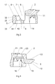
- the laying plate is a plastic molded part and has a square base body 1 with four outer walls 2. On two adjacent outer walls 2 each have a male element 3 is formed. At the other two opposite and also adjacent outer walls 2 each have a receiving area 4 is provided for the male element 3.
- the length of the male element 3 corresponds to approximately one quarter of the length of the outer wall 2 and the length of the receiving area 4 corresponds to approximately one third of the length of the outer wall 2.
- the receiving area 4 has a receiving element 5 and an insertion opening 6 for the male element 3.
- the receiving element 5 protrudes from the outer wall 2 and extends parallel to the outer wall 2. In the receiving element 5 is an upwardly open, elongated and parallel to the outer wall 2 extending groove 7 is provided.
- the groove 7 has a side wall 8 remote from the outer wall 2, which has a bevelled shape.
- the chamfer is formed such that the side wall 8 seen from a base surface 9 of the groove 7 upwards towards the open area of the groove 7 more and more away from the outer wall 2.
- the beveled side wall 8 of the groove 7 merges with a rounding 10 in the base 9 of the groove 7.
- the sidewall 8 opposite side wall 11 of the groove 7 corresponds to the outside of the outer wall 2.
- the male element 3 also protrudes beyond the outer wall 2 and is integrally formed thereon.
- the male member 3 has the shape of an elongated web extending parallel to the outer wall 2 and has a lower run-on slope 12 in its front and lower regions.
- the run-up slope opposite to a flat support surface 13 is provided which comes into engagement with the receiving area 4 in the closed state with an inner surface 14 of the outer wall 2 to the plant.
- the inner surface 14 limits the region of the insertion opening 6 upwards.
- the lower portion 15 of the male member 3 is approximately straight and is adapted to the shape of the base 9 of the groove 7.
- the rear portion 16 of the male member 3 is the shape of the rounding 10 and the bevelled Side wall 8 of the groove 7 adapted.
- At the male member 3 are still side chamfers 17 are provided in addition to the lower run-on slope 12.
- the male element 3 is overall stable and solid.
- Fig. 5 shows a section through the receiving area 4 in a region which lies along the outer wall 2 outside of the insertion opening 6.
- the outer wall 2 is closed here and massive.
- the shape of the groove 7 is identical in this area as in the region of the insertion opening 6.
- the chamfered outer wall 8 and the rounding 10 and the base 9 are also provided here.
- the side wall 8 merges into a flat upper side 17.
- the outer wall 2 also has a rounding 18 in this area and is adapted to the shape of the groove 7.
- the outer wall 2 is rectangular in cross-section.
- the male element 3 of a first laying plate is inserted into the insertion opening 6 of the receiving region 4 of a second laying plate at an oblique angle of for example 45 °. Subsequently, the first installation plate is lowered or simply dropped. At the same time the support surface 13 comes to rest against the inner surface 14 of the outer wall 2. The first installation plate is now reliably connected to the second installation plate, since the male element 3 on the one hand on the inner surface 14 of Outer wall 2 and on the other hand in the groove 7 is supported, so that, for example, even with a bending of the two installation plates upwards, the connection can not solve.
- the connection of two or more plates can be done on a floor.
- pre-assembled laying plate units can be delivered to a location where they are then easily and quickly mounted to the example event floor. at a flat mounting in two directions as well as in the assembly of several single installation panels over corner raised already lying on the floor laying plate unit.
- the male elements of the laying plate unit to be mounted are now inserted at an oblique angle into the receiving areas of the raised laying plate unit and into the receiving areas of the lying on the ground and the raised laying plate unit corner above laying plate unit. Subsequently, the laying plate units are dropped to the ground, whereby the locking of the laying plates takes place.
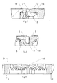
- a rivet 19 is provided, which is inserted into a receiving opening 20 on the upper side 21 of the main body 1 and into a receiving opening 22 of the receiving element 5.
- the receiving opening 20 is arranged close to the male element 3 and the receiving opening 22 is arranged centrally in the receiving element 5 and in the direction away from the outer wall 2 region of the receiving element 5.
- the rivet 19 has an upper head area 23, a lower head area 24 and a central area 25.
- the upper head portion 23 consists of a rounded rivet head.
- the lower head region 24 consists of a rounded rivet head 26 with a cylindrical projection 27.
- the diameter of the lower head region 24 is smaller than the diameter of the upper head region 23.
- a first conical region 28 is formed in opposite directions to the second conical region 29.
- the second conical region 29 and the third conical region 30 both expand upwards, but different opening angles are provided.
- a corresponding conical region 31 is provided in the receiving opening 20.
- a corresponding conical region 32 is provided in the receiving opening 22 in the receiving element 5. The lower end 33 of this conical portion 32 is formed smaller than the diameter of the rivet head 26.
- the rivet is simply beaten from above through the top 21 of the installation plate and through the receiving element 5, wherein the lower end 33 of the conical area 32 somewhat widened, since the rivet head 26 is larger than this area. Once the rivet head 26 through this area The rivet head 26 can now no longer slip back, since the passage to the conical portion 32 is smaller than the cylindrical portion 27 of the rivet head 26.
- two installation plates are securely connected to each other and only by destroying the Rivet, for example by knocking off the rivet head 26, these two installation plates can be separated again.
- a plurality of corrugations 35 are provided on the upper side 21 of the main body 1, which are triangular in cross section. Furthermore, a plurality of holes 36 are provided on the upper side 21 of the main body 1, through which an irrigation of the substrate or a ventilation of the substrate can be done.
- a laying plate system can be created, which is on the one hand in the simplest way to connect and to solve and on the other hand can be laid on uneven floors in the outdoor area, since the mechanical flexibility of the compounds is large.
Landscapes
- Engineering & Computer Science (AREA)
- Architecture (AREA)
- Civil Engineering (AREA)
- Structural Engineering (AREA)
- Floor Finish (AREA)
- Finishing Walls (AREA)
Applications Claiming Priority (1)
| Application Number | Priority Date | Filing Date | Title |
|---|---|---|---|
| DE201210008187 DE102012008187B4 (de) | 2012-04-26 | 2012-04-26 | Verlegeplatte |
Publications (2)
| Publication Number | Publication Date |
|---|---|
| EP2657401A1 true EP2657401A1 (fr) | 2013-10-30 |
| EP2657401B1 EP2657401B1 (fr) | 2015-04-15 |
Family
ID=47915413
Family Applications (1)
| Application Number | Title | Priority Date | Filing Date |
|---|---|---|---|
| EP13001400.4A Not-in-force EP2657401B1 (fr) | 2012-04-26 | 2013-03-19 | Plaque de montage |
Country Status (2)
| Country | Link |
|---|---|
| EP (1) | EP2657401B1 (fr) |
| DE (1) | DE102012008187B4 (fr) |
Cited By (1)
| Publication number | Priority date | Publication date | Assignee | Title |
|---|---|---|---|---|
| CN106284014A (zh) * | 2016-08-04 | 2017-01-04 | 苏州汇诚智造工业设计有限公司 | 十字组合草坪砖及其制造和施工方法 |
Citations (7)
| Publication number | Priority date | Publication date | Assignee | Title |
|---|---|---|---|---|
| EP0135749A1 (fr) * | 1983-08-19 | 1985-04-03 | Klöckner Stahl Gmbh | Elément en forme de plaque pour une voie de roulement |
| EP0224095A2 (fr) * | 1985-11-22 | 1987-06-03 | Dr. Spiess Kunststoff-Recycling GmbH & Co. | Panneau de treillis en matière synthétique, en particulier en matière synthétique de recyclage |
| EP0621373A2 (fr) | 1993-04-21 | 1994-10-26 | Krauss-Maffei Aktiengesellschaft | Revêtement de sol en plaques hexagonales couplées amoviblement |
| WO2000009810A1 (fr) * | 1998-08-14 | 2000-02-24 | Eve Trakway Limited | Systeme de chaussees transportable |
| EP1845195A2 (fr) * | 2006-04-12 | 2007-10-17 | Christian Deforges | Chaussée provisoire transportable et plaques pour réaliser une telle chaussée. |
| DE202010005276U1 (de) | 2010-04-21 | 2010-09-30 | Purus Arzberg Gmbh | Verlegeplatte |
| EP2327846A2 (fr) * | 2009-11-30 | 2011-06-01 | Kurt Stumpf | Plaque de fond en matière synthétique |
Family Cites Families (8)
| Publication number | Priority date | Publication date | Assignee | Title |
|---|---|---|---|---|
| GB816243A (en) * | 1956-10-16 | 1959-07-08 | Seby Carl J | Improvements in or relating to elements for forming floor covering or the like |
| CH467408A (de) * | 1968-03-14 | 1969-01-15 | Edo Plast Ets | Boden- oder Wandplatte |
| DE3219164C2 (de) * | 1981-06-30 | 1985-05-02 | Salzgitter Ag, 1000 Berlin Und 3320 Salzgitter | Fahrbahn aus Sechseckplatten und halbierten Sechseckplatten |
| GB2126106A (en) * | 1982-07-14 | 1984-03-21 | Sava Soc Alluminio Veneto | Floor surface for fencing competitions |
| DE9407901U1 (de) * | 1994-05-17 | 1994-08-25 | KA-Müllbehälter-Service GmbH, 61184 Karben | Verbundplatte |
| DE19640128A1 (de) * | 1996-09-28 | 1998-04-02 | Hoerner Clemens Dipl Betriebsw | Bodenbelag-Element |
| SE522860C2 (sv) * | 2000-03-10 | 2004-03-09 | Pergo Europ Ab | Vertikalt förenade golvelement innefattande en kombination av olika golvelement |
| US7364383B2 (en) * | 2004-06-23 | 2008-04-29 | Ground Floor Systems, Llc | Roll-up surface, system and method |
-
2012
- 2012-04-26 DE DE201210008187 patent/DE102012008187B4/de not_active Expired - Fee Related
-
2013
- 2013-03-19 EP EP13001400.4A patent/EP2657401B1/fr not_active Not-in-force
Patent Citations (7)
| Publication number | Priority date | Publication date | Assignee | Title |
|---|---|---|---|---|
| EP0135749A1 (fr) * | 1983-08-19 | 1985-04-03 | Klöckner Stahl Gmbh | Elément en forme de plaque pour une voie de roulement |
| EP0224095A2 (fr) * | 1985-11-22 | 1987-06-03 | Dr. Spiess Kunststoff-Recycling GmbH & Co. | Panneau de treillis en matière synthétique, en particulier en matière synthétique de recyclage |
| EP0621373A2 (fr) | 1993-04-21 | 1994-10-26 | Krauss-Maffei Aktiengesellschaft | Revêtement de sol en plaques hexagonales couplées amoviblement |
| WO2000009810A1 (fr) * | 1998-08-14 | 2000-02-24 | Eve Trakway Limited | Systeme de chaussees transportable |
| EP1845195A2 (fr) * | 2006-04-12 | 2007-10-17 | Christian Deforges | Chaussée provisoire transportable et plaques pour réaliser une telle chaussée. |
| EP2327846A2 (fr) * | 2009-11-30 | 2011-06-01 | Kurt Stumpf | Plaque de fond en matière synthétique |
| DE202010005276U1 (de) | 2010-04-21 | 2010-09-30 | Purus Arzberg Gmbh | Verlegeplatte |
Cited By (1)
| Publication number | Priority date | Publication date | Assignee | Title |
|---|---|---|---|---|
| CN106284014A (zh) * | 2016-08-04 | 2017-01-04 | 苏州汇诚智造工业设计有限公司 | 十字组合草坪砖及其制造和施工方法 |
Also Published As
| Publication number | Publication date |
|---|---|
| DE102012008187B4 (de) | 2014-04-03 |
| EP2657401B1 (fr) | 2015-04-15 |
| DE102012008187A1 (de) | 2013-10-31 |
Similar Documents
| Publication | Publication Date | Title |
|---|---|---|
| EP2672034B1 (fr) | Pied de support pour le guidage et la distribution de forces sur un sous-sol sensible à la pression et système de support doté d'un tel pied de support | |
| EP2183445B1 (fr) | Coffrage de plafond comportant des moyens de support pour panneaux de coffrage | |
| EP3440281A1 (fr) | Ferrure pour une plinthe d'un échafaudage | |
| DE202004015811U1 (de) | Befestigungsvorrichtung für mindestens einen Sonnenkollektor | |
| EP2754773B1 (fr) | Sous-structure pour un revêtement de sol | |
| DE102017003694B4 (de) | Bausatz zur Errichtung einer Unterkonstruktion für Terrassenlaufflächen | |
| DE102014106068B4 (de) | Vorrichtung zur Verbindung zweier einander gegenüberliegender plattenförmiger Schalungselemente | |
| EP2657401B1 (fr) | Plaque de montage | |
| EP3461963B1 (fr) | Système porteur et système d'éléments de connexion permettant la connexion des porteurs | |
| DE102005060817B4 (de) | Nutenstein, Ankerstein, Profilverbindersystem und Profilverbund | |
| DE202016101225U1 (de) | Unterbauelement mit Wabenstruktur und Höhenjustierungsmitteln | |
| DE3038019A1 (de) | Aufhaengevorrichtung fuer rasterdecken mit u-foermigen lamellen | |
| AT518364B1 (de) | Unterkonstruktion für ein Bauwerk | |
| DE102015010894B4 (de) | Montagebausatz für den Terrassenbau | |
| WO2003040496A1 (fr) | Dispositif de fixation de sections d'une cloture grillagee a un pieu | |
| DE102022104203A1 (de) | Doppelbodensystem | |
| DE102009034243B3 (de) | Rückdrehsicher höhenverstellbares Stelzlager für offenfugig zu verlegende Platten mit Fugenkreuz | |
| DE102016116018B3 (de) | Verbindungssystem | |
| DE102012205047B4 (de) | Steckverbinderelement und Steckverbindungssystem zur Verbindung zweier Bauteile | |
| DE3232105A1 (de) | Verbindungsvorrichtung fuer eine vorgehaengte wand- oder deckenverkleidung | |
| EP0027196B1 (fr) | Structure de recouvrement avec dispositif de pinçage et élément de recouvrement | |
| EP3137699B1 (fr) | Procédé de réalisation d'une liaison montant-traverse | |
| EP3816366B1 (fr) | Construction d'appui pourvu de plusieurs éléments profilés allongés | |
| DE102007063837B3 (de) | Set aus tafelförmigen Paneelen mit bewegbarem Verriegelungselement | |
| DE202023100052U1 (de) | System zum Lagern von Plattenelementen über einem Untergrund |
Legal Events
| Date | Code | Title | Description |
|---|---|---|---|
| PUAI | Public reference made under article 153(3) epc to a published international application that has entered the european phase |
Free format text: ORIGINAL CODE: 0009012 |
|
| AK | Designated contracting states |
Kind code of ref document: A1 Designated state(s): AL AT BE BG CH CY CZ DE DK EE ES FI FR GB GR HR HU IE IS IT LI LT LU LV MC MK MT NL NO PL PT RO RS SE SI SK SM TR |
|
| AX | Request for extension of the european patent |
Extension state: BA ME |
|
| 17P | Request for examination filed |
Effective date: 20131122 |
|
| RBV | Designated contracting states (corrected) |
Designated state(s): AL AT BE BG CH CY CZ DE DK EE ES FI FR GB GR HR HU IE IS IT LI LT LU LV MC MK MT NL NO PL PT RO RS SE SI SK SM TR |
|
| 17Q | First examination report despatched |
Effective date: 20140715 |
|
| GRAP | Despatch of communication of intention to grant a patent |
Free format text: ORIGINAL CODE: EPIDOSNIGR1 |
|
| INTG | Intention to grant announced |
Effective date: 20150107 |
|
| GRAS | Grant fee paid |
Free format text: ORIGINAL CODE: EPIDOSNIGR3 |
|
| GRAA | (expected) grant |
Free format text: ORIGINAL CODE: 0009210 |
|
| AK | Designated contracting states |
Kind code of ref document: B1 Designated state(s): AL AT BE BG CH CY CZ DE DK EE ES FI FR GB GR HR HU IE IS IT LI LT LU LV MC MK MT NL NO PL PT RO RS SE SI SK SM TR |
|
| REG | Reference to a national code |
Ref country code: GB Ref legal event code: FG4D Free format text: NOT ENGLISH Ref country code: CH Ref legal event code: EP |
|
| REG | Reference to a national code |
Ref country code: IE Ref legal event code: FG4D Free format text: LANGUAGE OF EP DOCUMENT: GERMAN |
|
| REG | Reference to a national code |
Ref country code: AT Ref legal event code: REF Ref document number: 722062 Country of ref document: AT Kind code of ref document: T Effective date: 20150515 |
|
| REG | Reference to a national code |
Ref country code: DE Ref legal event code: R096 Ref document number: 502013000542 Country of ref document: DE Effective date: 20150528 |
|
| REG | Reference to a national code |
Ref country code: CH Ref legal event code: NV Representative=s name: SCHNEIDER FELDMANN AG PATENT- UND MARKENANWAEL, CH |
|
| REG | Reference to a national code |
Ref country code: NL Ref legal event code: VDEP Effective date: 20150415 |
|
| REG | Reference to a national code |
Ref country code: LT Ref legal event code: MG4D |
|
| PG25 | Lapsed in a contracting state [announced via postgrant information from national office to epo] |
Ref country code: NL Free format text: LAPSE BECAUSE OF FAILURE TO SUBMIT A TRANSLATION OF THE DESCRIPTION OR TO PAY THE FEE WITHIN THE PRESCRIBED TIME-LIMIT Effective date: 20150415 |
|
| PG25 | Lapsed in a contracting state [announced via postgrant information from national office to epo] |
Ref country code: NO Free format text: LAPSE BECAUSE OF FAILURE TO SUBMIT A TRANSLATION OF THE DESCRIPTION OR TO PAY THE FEE WITHIN THE PRESCRIBED TIME-LIMIT Effective date: 20150715 Ref country code: LT Free format text: LAPSE BECAUSE OF FAILURE TO SUBMIT A TRANSLATION OF THE DESCRIPTION OR TO PAY THE FEE WITHIN THE PRESCRIBED TIME-LIMIT Effective date: 20150415 Ref country code: ES Free format text: LAPSE BECAUSE OF FAILURE TO SUBMIT A TRANSLATION OF THE DESCRIPTION OR TO PAY THE FEE WITHIN THE PRESCRIBED TIME-LIMIT Effective date: 20150415 Ref country code: FI Free format text: LAPSE BECAUSE OF FAILURE TO SUBMIT A TRANSLATION OF THE DESCRIPTION OR TO PAY THE FEE WITHIN THE PRESCRIBED TIME-LIMIT Effective date: 20150415 Ref country code: HR Free format text: LAPSE BECAUSE OF FAILURE TO SUBMIT A TRANSLATION OF THE DESCRIPTION OR TO PAY THE FEE WITHIN THE PRESCRIBED TIME-LIMIT Effective date: 20150415 Ref country code: PT Free format text: LAPSE BECAUSE OF FAILURE TO SUBMIT A TRANSLATION OF THE DESCRIPTION OR TO PAY THE FEE WITHIN THE PRESCRIBED TIME-LIMIT Effective date: 20150817 |
|
| PG25 | Lapsed in a contracting state [announced via postgrant information from national office to epo] |
Ref country code: GR Free format text: LAPSE BECAUSE OF FAILURE TO SUBMIT A TRANSLATION OF THE DESCRIPTION OR TO PAY THE FEE WITHIN THE PRESCRIBED TIME-LIMIT Effective date: 20150716 Ref country code: LV Free format text: LAPSE BECAUSE OF FAILURE TO SUBMIT A TRANSLATION OF THE DESCRIPTION OR TO PAY THE FEE WITHIN THE PRESCRIBED TIME-LIMIT Effective date: 20150415 Ref country code: IS Free format text: LAPSE BECAUSE OF FAILURE TO SUBMIT A TRANSLATION OF THE DESCRIPTION OR TO PAY THE FEE WITHIN THE PRESCRIBED TIME-LIMIT Effective date: 20150815 Ref country code: RS Free format text: LAPSE BECAUSE OF FAILURE TO SUBMIT A TRANSLATION OF THE DESCRIPTION OR TO PAY THE FEE WITHIN THE PRESCRIBED TIME-LIMIT Effective date: 20150415 |
|
| REG | Reference to a national code |
Ref country code: DE Ref legal event code: R097 Ref document number: 502013000542 Country of ref document: DE |
|
| PG25 | Lapsed in a contracting state [announced via postgrant information from national office to epo] |
Ref country code: DK Free format text: LAPSE BECAUSE OF FAILURE TO SUBMIT A TRANSLATION OF THE DESCRIPTION OR TO PAY THE FEE WITHIN THE PRESCRIBED TIME-LIMIT Effective date: 20150415 Ref country code: EE Free format text: LAPSE BECAUSE OF FAILURE TO SUBMIT A TRANSLATION OF THE DESCRIPTION OR TO PAY THE FEE WITHIN THE PRESCRIBED TIME-LIMIT Effective date: 20150415 |
|
| PLBE | No opposition filed within time limit |
Free format text: ORIGINAL CODE: 0009261 |
|
| STAA | Information on the status of an ep patent application or granted ep patent |
Free format text: STATUS: NO OPPOSITION FILED WITHIN TIME LIMIT |
|
| PG25 | Lapsed in a contracting state [announced via postgrant information from national office to epo] |
Ref country code: RO Free format text: LAPSE BECAUSE OF NON-PAYMENT OF DUE FEES Effective date: 20150415 Ref country code: CZ Free format text: LAPSE BECAUSE OF FAILURE TO SUBMIT A TRANSLATION OF THE DESCRIPTION OR TO PAY THE FEE WITHIN THE PRESCRIBED TIME-LIMIT Effective date: 20150415 Ref country code: SK Free format text: LAPSE BECAUSE OF FAILURE TO SUBMIT A TRANSLATION OF THE DESCRIPTION OR TO PAY THE FEE WITHIN THE PRESCRIBED TIME-LIMIT Effective date: 20150415 Ref country code: PL Free format text: LAPSE BECAUSE OF FAILURE TO SUBMIT A TRANSLATION OF THE DESCRIPTION OR TO PAY THE FEE WITHIN THE PRESCRIBED TIME-LIMIT Effective date: 20150415 |
|
| REG | Reference to a national code |
Ref country code: FR Ref legal event code: PLFP Year of fee payment: 4 |
|
| 26N | No opposition filed |
Effective date: 20160118 |
|
| PG25 | Lapsed in a contracting state [announced via postgrant information from national office to epo] |
Ref country code: IT Free format text: LAPSE BECAUSE OF FAILURE TO SUBMIT A TRANSLATION OF THE DESCRIPTION OR TO PAY THE FEE WITHIN THE PRESCRIBED TIME-LIMIT Effective date: 20150415 |
|
| PG25 | Lapsed in a contracting state [announced via postgrant information from national office to epo] |
Ref country code: SI Free format text: LAPSE BECAUSE OF FAILURE TO SUBMIT A TRANSLATION OF THE DESCRIPTION OR TO PAY THE FEE WITHIN THE PRESCRIBED TIME-LIMIT Effective date: 20150415 |
|
| PG25 | Lapsed in a contracting state [announced via postgrant information from national office to epo] |
Ref country code: BE Free format text: LAPSE BECAUSE OF NON-PAYMENT OF DUE FEES Effective date: 20160331 |
|
| PG25 | Lapsed in a contracting state [announced via postgrant information from national office to epo] |
Ref country code: LU Free format text: LAPSE BECAUSE OF FAILURE TO SUBMIT A TRANSLATION OF THE DESCRIPTION OR TO PAY THE FEE WITHIN THE PRESCRIBED TIME-LIMIT Effective date: 20160319 Ref country code: MC Free format text: LAPSE BECAUSE OF FAILURE TO SUBMIT A TRANSLATION OF THE DESCRIPTION OR TO PAY THE FEE WITHIN THE PRESCRIBED TIME-LIMIT Effective date: 20150415 |
|
| REG | Reference to a national code |
Ref country code: IE Ref legal event code: MM4A |
|
| PG25 | Lapsed in a contracting state [announced via postgrant information from national office to epo] |
Ref country code: IE Free format text: LAPSE BECAUSE OF NON-PAYMENT OF DUE FEES Effective date: 20160319 |
|
| REG | Reference to a national code |
Ref country code: FR Ref legal event code: PLFP Year of fee payment: 5 |
|
| PGFP | Annual fee paid to national office [announced via postgrant information from national office to epo] |
Ref country code: CH Payment date: 20170327 Year of fee payment: 5 |
|
| PGFP | Annual fee paid to national office [announced via postgrant information from national office to epo] |
Ref country code: GB Payment date: 20170327 Year of fee payment: 5 |
|
| PG25 | Lapsed in a contracting state [announced via postgrant information from national office to epo] |
Ref country code: SE Free format text: LAPSE BECAUSE OF FAILURE TO SUBMIT A TRANSLATION OF THE DESCRIPTION OR TO PAY THE FEE WITHIN THE PRESCRIBED TIME-LIMIT Effective date: 20150415 |
|
| PG25 | Lapsed in a contracting state [announced via postgrant information from national office to epo] |
Ref country code: MT Free format text: LAPSE BECAUSE OF FAILURE TO SUBMIT A TRANSLATION OF THE DESCRIPTION OR TO PAY THE FEE WITHIN THE PRESCRIBED TIME-LIMIT Effective date: 20150415 |
|
| REG | Reference to a national code |
Ref country code: DE Ref legal event code: R082 Ref document number: 502013000542 Country of ref document: DE Representative=s name: PATENT- UND RECHTSANWAELTE LOESENBECK, SPECHT,, DE Ref country code: DE Ref legal event code: R082 Ref document number: 502013000542 Country of ref document: DE Representative=s name: LOESENBECK UND KOLLEGEN, DE |
|
| REG | Reference to a national code |
Ref country code: FR Ref legal event code: PLFP Year of fee payment: 6 |
|
| PG25 | Lapsed in a contracting state [announced via postgrant information from national office to epo] |
Ref country code: CY Free format text: LAPSE BECAUSE OF FAILURE TO SUBMIT A TRANSLATION OF THE DESCRIPTION OR TO PAY THE FEE WITHIN THE PRESCRIBED TIME-LIMIT Effective date: 20150415 Ref country code: HU Free format text: LAPSE BECAUSE OF FAILURE TO SUBMIT A TRANSLATION OF THE DESCRIPTION OR TO PAY THE FEE WITHIN THE PRESCRIBED TIME-LIMIT; INVALID AB INITIO Effective date: 20130319 Ref country code: SM Free format text: LAPSE BECAUSE OF FAILURE TO SUBMIT A TRANSLATION OF THE DESCRIPTION OR TO PAY THE FEE WITHIN THE PRESCRIBED TIME-LIMIT Effective date: 20150415 |
|
| PGFP | Annual fee paid to national office [announced via postgrant information from national office to epo] |
Ref country code: FR Payment date: 20180326 Year of fee payment: 6 |
|
| PG25 | Lapsed in a contracting state [announced via postgrant information from national office to epo] |
Ref country code: MK Free format text: LAPSE BECAUSE OF FAILURE TO SUBMIT A TRANSLATION OF THE DESCRIPTION OR TO PAY THE FEE WITHIN THE PRESCRIBED TIME-LIMIT Effective date: 20150415 Ref country code: TR Free format text: LAPSE BECAUSE OF FAILURE TO SUBMIT A TRANSLATION OF THE DESCRIPTION OR TO PAY THE FEE WITHIN THE PRESCRIBED TIME-LIMIT Effective date: 20150415 |
|
| PG25 | Lapsed in a contracting state [announced via postgrant information from national office to epo] |
Ref country code: BG Free format text: LAPSE BECAUSE OF FAILURE TO SUBMIT A TRANSLATION OF THE DESCRIPTION OR TO PAY THE FEE WITHIN THE PRESCRIBED TIME-LIMIT Effective date: 20150415 |
|
| PG25 | Lapsed in a contracting state [announced via postgrant information from national office to epo] |
Ref country code: AL Free format text: LAPSE BECAUSE OF FAILURE TO SUBMIT A TRANSLATION OF THE DESCRIPTION OR TO PAY THE FEE WITHIN THE PRESCRIBED TIME-LIMIT Effective date: 20150415 |
|
| REG | Reference to a national code |
Ref country code: CH Ref legal event code: PL |
|
| GBPC | Gb: european patent ceased through non-payment of renewal fee |
Effective date: 20180319 |
|
| PG25 | Lapsed in a contracting state [announced via postgrant information from national office to epo] |
Ref country code: GB Free format text: LAPSE BECAUSE OF NON-PAYMENT OF DUE FEES Effective date: 20180319 Ref country code: CH Free format text: LAPSE BECAUSE OF NON-PAYMENT OF DUE FEES Effective date: 20180331 Ref country code: LI Free format text: LAPSE BECAUSE OF NON-PAYMENT OF DUE FEES Effective date: 20180331 |
|
| REG | Reference to a national code |
Ref country code: AT Ref legal event code: MM01 Ref document number: 722062 Country of ref document: AT Kind code of ref document: T Effective date: 20180319 |
|
| PG25 | Lapsed in a contracting state [announced via postgrant information from national office to epo] |
Ref country code: AT Free format text: LAPSE BECAUSE OF NON-PAYMENT OF DUE FEES Effective date: 20180319 |
|
| PG25 | Lapsed in a contracting state [announced via postgrant information from national office to epo] |
Ref country code: FR Free format text: LAPSE BECAUSE OF NON-PAYMENT OF DUE FEES Effective date: 20190331 |
|
| PGFP | Annual fee paid to national office [announced via postgrant information from national office to epo] |
Ref country code: DE Payment date: 20240503 Year of fee payment: 12 |
|
| REG | Reference to a national code |
Ref country code: DE Ref legal event code: R119 Ref document number: 502013000542 Country of ref document: DE |
|
| PG25 | Lapsed in a contracting state [announced via postgrant information from national office to epo] |
Ref country code: DE Free format text: LAPSE BECAUSE OF NON-PAYMENT OF DUE FEES Effective date: 20251001 |