EP2327880A2 - Système de rétention et d'élévation d'éolienne et plateforme d'exploitation mobile au-dessus de l'eau - Google Patents
Système de rétention et d'élévation d'éolienne et plateforme d'exploitation mobile au-dessus de l'eau Download PDFInfo
- Publication number
- EP2327880A2 EP2327880A2 EP10290151A EP10290151A EP2327880A2 EP 2327880 A2 EP2327880 A2 EP 2327880A2 EP 10290151 A EP10290151 A EP 10290151A EP 10290151 A EP10290151 A EP 10290151A EP 2327880 A2 EP2327880 A2 EP 2327880A2
- Authority
- EP
- European Patent Office
- Prior art keywords
- wind turbine
- lifting system
- platform body
- above water
- holding
- Prior art date
- Legal status (The legal status is an assumption and is not a legal conclusion. Google has not performed a legal analysis and makes no representation as to the accuracy of the status listed.)
- Withdrawn
Links
- XLYOFNOQVPJJNP-UHFFFAOYSA-N water Substances O XLYOFNOQVPJJNP-UHFFFAOYSA-N 0.000 title claims abstract description 83
- 238000009434 installation Methods 0.000 claims abstract description 68
- 230000007246 mechanism Effects 0.000 claims description 40
- 238000005096 rolling process Methods 0.000 claims description 6
- 230000006978 adaptation Effects 0.000 claims description 2
- 238000005516 engineering process Methods 0.000 abstract description 3
- 230000000694 effects Effects 0.000 description 5
- 238000007667 floating Methods 0.000 description 5
- 230000001747 exhibiting effect Effects 0.000 description 2
- 230000004048 modification Effects 0.000 description 2
- 238000012986 modification Methods 0.000 description 2
- 230000009466 transformation Effects 0.000 description 2
- 230000003044 adaptive effect Effects 0.000 description 1
- 238000010276 construction Methods 0.000 description 1
- 238000010248 power generation Methods 0.000 description 1
- 238000003809 water extraction Methods 0.000 description 1
Images


Classifications
-
- B—PERFORMING OPERATIONS; TRANSPORTING
- B63—SHIPS OR OTHER WATERBORNE VESSELS; RELATED EQUIPMENT
- B63B—SHIPS OR OTHER WATERBORNE VESSELS; EQUIPMENT FOR SHIPPING
- B63B35/00—Vessels or similar floating structures specially adapted for specific purposes and not otherwise provided for
- B63B35/44—Floating buildings, stores, drilling platforms, or workshops, e.g. carrying water-oil separating devices
- B63B35/4413—Floating drilling platforms, e.g. carrying water-oil separating devices
-
- F—MECHANICAL ENGINEERING; LIGHTING; HEATING; WEAPONS; BLASTING
- F03—MACHINES OR ENGINES FOR LIQUIDS; WIND, SPRING, OR WEIGHT MOTORS; PRODUCING MECHANICAL POWER OR A REACTIVE PROPULSIVE THRUST, NOT OTHERWISE PROVIDED FOR
- F03D—WIND MOTORS
- F03D13/00—Assembly, mounting or commissioning of wind motors; Arrangements specially adapted for transporting wind motor components
- F03D13/10—Assembly of wind motors; Arrangements for erecting wind motors
-
- F—MECHANICAL ENGINEERING; LIGHTING; HEATING; WEAPONS; BLASTING
- F03—MACHINES OR ENGINES FOR LIQUIDS; WIND, SPRING, OR WEIGHT MOTORS; PRODUCING MECHANICAL POWER OR A REACTIVE PROPULSIVE THRUST, NOT OTHERWISE PROVIDED FOR
- F03D—WIND MOTORS
- F03D13/00—Assembly, mounting or commissioning of wind motors; Arrangements specially adapted for transporting wind motor components
- F03D13/40—Arrangements or methods specially adapted for transporting wind motor components
-
- F—MECHANICAL ENGINEERING; LIGHTING; HEATING; WEAPONS; BLASTING
- F05—INDEXING SCHEMES RELATING TO ENGINES OR PUMPS IN VARIOUS SUBCLASSES OF CLASSES F01-F04
- F05B—INDEXING SCHEME RELATING TO WIND, SPRING, WEIGHT, INERTIA OR LIKE MOTORS, TO MACHINES OR ENGINES FOR LIQUIDS COVERED BY SUBCLASSES F03B, F03D AND F03G
- F05B2230/00—Manufacture
- F05B2230/60—Assembly methods
- F05B2230/61—Assembly methods using auxiliary equipment for lifting or holding
- F05B2230/6102—Assembly methods using auxiliary equipment for lifting or holding carried on a floating platform
-
- F—MECHANICAL ENGINEERING; LIGHTING; HEATING; WEAPONS; BLASTING
- F05—INDEXING SCHEMES RELATING TO ENGINES OR PUMPS IN VARIOUS SUBCLASSES OF CLASSES F01-F04
- F05B—INDEXING SCHEME RELATING TO WIND, SPRING, WEIGHT, INERTIA OR LIKE MOTORS, TO MACHINES OR ENGINES FOR LIQUIDS COVERED BY SUBCLASSES F03B, F03D AND F03G
- F05B2240/00—Components
- F05B2240/90—Mounting on supporting structures or systems
- F05B2240/95—Mounting on supporting structures or systems offshore
-
- Y—GENERAL TAGGING OF NEW TECHNOLOGICAL DEVELOPMENTS; GENERAL TAGGING OF CROSS-SECTIONAL TECHNOLOGIES SPANNING OVER SEVERAL SECTIONS OF THE IPC; TECHNICAL SUBJECTS COVERED BY FORMER USPC CROSS-REFERENCE ART COLLECTIONS [XRACs] AND DIGESTS
- Y02—TECHNOLOGIES OR APPLICATIONS FOR MITIGATION OR ADAPTATION AGAINST CLIMATE CHANGE
- Y02E—REDUCTION OF GREENHOUSE GAS [GHG] EMISSIONS, RELATED TO ENERGY GENERATION, TRANSMISSION OR DISTRIBUTION
- Y02E10/00—Energy generation through renewable energy sources
- Y02E10/70—Wind energy
- Y02E10/72—Wind turbines with rotation axis in wind direction
-
- Y—GENERAL TAGGING OF NEW TECHNOLOGICAL DEVELOPMENTS; GENERAL TAGGING OF CROSS-SECTIONAL TECHNOLOGIES SPANNING OVER SEVERAL SECTIONS OF THE IPC; TECHNICAL SUBJECTS COVERED BY FORMER USPC CROSS-REFERENCE ART COLLECTIONS [XRACs] AND DIGESTS
- Y02—TECHNOLOGIES OR APPLICATIONS FOR MITIGATION OR ADAPTATION AGAINST CLIMATE CHANGE
- Y02E—REDUCTION OF GREENHOUSE GAS [GHG] EMISSIONS, RELATED TO ENERGY GENERATION, TRANSMISSION OR DISTRIBUTION
- Y02E10/00—Energy generation through renewable energy sources
- Y02E10/70—Wind energy
- Y02E10/727—Offshore wind turbines
-
- Y—GENERAL TAGGING OF NEW TECHNOLOGICAL DEVELOPMENTS; GENERAL TAGGING OF CROSS-SECTIONAL TECHNOLOGIES SPANNING OVER SEVERAL SECTIONS OF THE IPC; TECHNICAL SUBJECTS COVERED BY FORMER USPC CROSS-REFERENCE ART COLLECTIONS [XRACs] AND DIGESTS
- Y02—TECHNOLOGIES OR APPLICATIONS FOR MITIGATION OR ADAPTATION AGAINST CLIMATE CHANGE
- Y02P—CLIMATE CHANGE MITIGATION TECHNOLOGIES IN THE PRODUCTION OR PROCESSING OF GOODS
- Y02P70/00—Climate change mitigation technologies in the production process for final industrial or consumer products
- Y02P70/50—Manufacturing or production processes characterised by the final manufactured product
Definitions
- the present invention relates to the field of offshore wind turbine installation technology, in particular a wind turbine holding and lifting system for a movable operating platform above water.
- the present invention further relates to a movable operating platform above water.
- a wind turbine generally comprises a tower, a rotor and a nacelle, wherein the nacelle is provided with a generator, a gearbox and a main shaft.
- the bottom of the tower is installed to the wind turbine foundation of the wind farm, and the rotor and the nacelle are installed at the top of the wind turbine tower.
- the rotor which is rotatable under the action of wind drives the power generator in the nacelle to generate electrical energy and thereby the transformation of wind energy into electrical energy is achieved.
- each part of the wind turbine is heavy.
- the total weight of the nacelle of the wind turbine is up to 300 tons.
- Those relatively large parts such as the gearbox, the generator inside the nacelle each may have a weight up to 60 tons in variety.
- the first solution is to install the wind turbine by part. Firstly, the wind turbine parts such as tower, a nacelle, blades and so on are carried to the assembly port. Then such parts are carried by a carriage ship to a wind farm in a predetermined offshore sea area. On the wind farm, a movable operating platform above water is served as a basis on which the respective parts of the wind turbine are hoisted on-site to assemble the wind turbine.
- This solution has the following disadvantages: the movable offshore operating platform has a deep draft so that it cannot operate in an intertidal zone or a shallow sea. In addition, it is impossible to use the leg structure of the present movable offshore operating platform in a muddy coast.
- the second solution is to install the wind turbine in one piece. After having been assembled in a port, the wind turbine is integrally conveyed by a carried ship to a wind farm in a predetermined sea area. Then the wind turbine is hoisted by a large floating vessel.
- the crane ship In the second solution, the crane ship is floating with poor stability.
- the high and long boom of the crane ship When the high and long boom of the crane ship is used to hoist the wind turbine, the swinging of the ship body makes the wind turbine swings more severely. Since it is difficult to align the installation site of the bottom of the tower with that of foundation if the wind turbine keeps swinging, the installation of the wind turbine becomes very difficult.
- the stability of the crane ship is crucial when hoisting the entire wind turbine, the wind turbine has to be installed only when the wind is fair and the sea is calm, that is, the operation time is determined by the weather.
- the large floating vessel ship is not exclusively used for installation of the wind turbine, the using or renting fee is very expressive, adding to the installation cost of the wind turbine. Furthermore, the large floating vessel ship has a deep draft and thus cannot be used to hoist in an intertidal zone or a shallow sea area, so that this solution is restricted by the installation area.
- the present invention provides a wind turbine holding and lifting system for a movable operating platform above water, characterized in that , it comprises a door-type installation frame, a wind turbine lifting device and enclasping means for clamping a wind turbine tower, the door-type installation frame including a first leg, a second leg and no less than one beam fixed between the first and second legs, the enclasping means being arranged on the beams, the wind turbine lifting device being fixed to the door-type installation frame with its lifting end connected to the wind turbine tower.
- the beam comprises a first beam portion connected to the first leg and a second beam portion connected to the second leg, the enclasping means being arranged between the first and second beam portions.
- the enclasping means comprises a first buckling member, a second buckling member, a third buckling member and a fourth buckling member each having a hinged end and a buckled end, the hinged ends of the first buckling member and the second buckling member being hinged at the inner end of the first beam portion, and the hinged ends of the third buckling member and the fourth buckling member being hinged at the inner end of the second beam portion; a swing mechanisms is attached to the outer side of each of the first buckling member, the second buckling member, the third buckling member and the fourth buckling member, and a support mechanism for clamping the wind turbine tower is attached to inner side of each of the first buckling member the second buckling member, the third buckling member and the fourth buckling member; the buckled ends of adjacent buckling members are locked by means of locking members after the buckling members on the first beam portion are engaged with adjacent buckling members on the second beam portion.
- the swing mechanism allows each of the first buckling member, the second buckling member, the third buckling member and the fourth buckling member to pivot about its hinged ends respectively.
- the support mechanism is telescopic for adaptation to wind turbine towers of various diameters and clamping them.
- the swing mechanism is a hydraulic cylinder.
- the support mechanism is a hydraulic cylinder or a hydro-pneumatic spring.
- the locking member is a locking pin.
- it comprises two beams with the enclasping means thereon being aligned in the vertical direction.
- the wind turbine lifting device is a wind turbine hoist fixing to the beam or to the first or second leg and the wire ropes of the wind turbine hoist are connected to the wind turbine tower.
- the wind turbine holding and lifting system of the present invention comprises a door-shape installation frame and a wind turbine lifting device, wherein the beams of the door-type installation frame are provided with enclasping means for clamping the wind turbine tower and the wind turbine lifting device is fixed to the door-type installation frame, with the lifting end of the wind turbine lifting device being connected to the wind turbine tower.
- the wind turbine holding and lifting system of the present invention can be used for a movable operating platform above water.
- the enclasping means are capable of clamping the tower of the wind turbine in a horizontal plane, while the wind turbine lifting device is capable of constraining the wind turbine in a vertical direction.
- the movable operating platform above water is moved to a wind turbine foundation position of a wind turbine farm; the wind turbine holding and lifting system with a wind turbine fixed thereto is moved to a position corresponding to the wind turbine foundation; the installation part of the base of the wind turbine tower is aligned with that of the wind turbine foundation; the base of the wind turbine tower is fix to the wind turbine foundation by means of a fixing connector; the enclasping means and the wind turbine lifting device is released and the wind turbine holding and lifting system is moved away from the wind turbine; the movable operating platform above water is moved away from the wind farm; thus, the installation operation of the wind turbine is accomplished.
- the wind turbine holding and lifting system with such a structure is capable of fixing the wind turbine on the movable operating platform above water.
- the wind turbine Upon installation, the wind turbine has a high resistance to wind load.
- the effect that the swinging of the ship body makes the wind turbine swings more severely is reduced due to the relatively low fixing position of the wind turbine.
- the installation part at the bottom of the wind turbine tower can be precisely aligned with that of the wind turbine foundation and thus facilitate the installation.
- the cost for installation is reduced since it is unnecessary to rent a large crane ship.
- the movable operating platform above water is not limited to the draft depth and thus can be applied in wind turbine installation at various sea areas.
- the upper surface of the platform body is provided with longitudinal guide rails extending along the length of the platform body, and bottom surfaces of the first and second legs of the wind turbine holding and lifting system are provided with longitudinal rollers to fit with the longitudinal guide rails; driven by drive means, the wind turbine holding and lifting system is movable along the longitudinal rails.
- the upper surface of the platform body is provided with longitudinal guide rails extending longitudinally along the platform body and guide trays are arranged between the wind turbine holding and lifting system and the platform body, the bottom surfaces of the guide trays being provided with longitudinal rollers fitting with the longitudinal guide rails, the upper surfaces of the guide trays being provided with transverse guide rails extending transversely along the platform body, the bottom surfaces of the first and second legs of the wind turbine holding and lifting system being provided with transverse rail grooves fitting with the transverse guide rails; driven by drive means, the first wind turbine holding and lifting system is capable of rolling along the longitudinal or transverse guide rails.
- the drive means is a hydraulic cylinder.
- the platform body is provided with no less than one anchor winches.
- anchor winches being arranged symmetrically at the sides of the platform body.
- the bottom of the platform body has a flat structure.
- the sides of the platform body are provided with no less than one bucket legs.
- platform body lifting means being installed on the platform body, the lifting end of the platform body lifting means being connected to the bucket leg.
- an end of the platform body is provided with an locating groove for interfitting with the wind turbine foundation, the locating groove being shaped for adaption to the wind turbine foundation.
- both ends of the platform body are provided with locating grooves.
- two or more draft depth adjusting means are attached to the sides of the platform body and are symmetrically arranged.
- the draft depth adjusting means comprise: an airbag for adjusting the waterplane area of the platform body; an inflation system for controlling the inflation and deflation of the airbag; a telescopic mechanism connected to the airbag for controlling the extension and retraction of the airbag; a fixing holder for fixing the telescopic mechanism to the platform body.
- a manipulating device of the telescopic mechanism is chosen from one of an oil cylinder, an air cylinder or an electrical pushrod; the telescopic mechanism comprises a plurality of telescopic units connected in series; the telescopic units are extendable and retractable sections in the manner of a parallelogram four-bar mechanism.
- the platform body is equipped with a power system for self-navigation, or is not equipped with such a power system and is towed by a tugboat.
- the movable operating platform above water is equipped with the aforesaid wind turbine holding and lifting system which, driven by the drive means, is longitudinally or transversely movable along the platform body.
- the components such as the wind turbine tower, the impeller, the nacelle and so on are assembled into an integral wind turbine at the dock.
- a hoisting means is used to hoist the wind turbine to an upper surface of the platform body with the bottom of the wind turbine tower facing downwardly and the wind turbine tower exhibiting a vertical state.
- the enclasping means of the wind turbine holding and lifting system firmly clamps the wind turbine tower and the lifting end of the wind turbine lifting device is connected to the wind turbine tower, such that the wind turbine is fixed at a horizontal plane and in the vertical direction by the wind turbine holding and lifting system.
- the movable operating platform above water is transported to an offshore wind farm, with the ends of the movable operating platform above water in alignment with the wind turbine foundation of the wind farm.
- a wind turbine is lifted to a target height by the wind turbine lifting device.
- the wind turbine holding and lifting system is moved to the wind turbine installation position on the wind turbine foundation to align the installation site at the bottom of the wind turbine with that of the wind turbine foundation.
- the wind turbine is lowered onto the wind turbine foundation by the wind turbine lifting device and is connected therewith via the installation bolts.
- the enclasping means and the wind turbine lifting device is then released, the wind turbine holding and lifting system is removed away from the wind turbine and the movable operating platform above water is removed away from the wind farm. To this end, the installation operation of wind turbines is accomplished.
- the movable operating platform above water with such a structure can fix the wind turbine by means of the wind turbine holding and lifting system, with the wind turbine movable longitudinally or transversely along with the wind turbine holding and lifting system.
- a movable offshore operating platform can not only transport wind turbines, but also serve as the working table for installing the wind turbines.
- the wind turbines are fixed by the wind turbine holding and lifting system and thus are capable of bearing a relatively large wind load.
- the effect that the swinging of the ship body makes the wind turbine swings more severely is reduced due to the relatively low fixing position of the wind turbine.
- the installation part at the bottom of the wind turbine tower can be precisely aligned with that of the wind turbine foundation and thus facilitate the installation.
- the cost for installation is reduced since it is unnecessary to rent a large crane ship.
- the movable operating platform above water is not limited to the draft depth and thus can be applied in wind turbine installation at various sea areas.
- One key of the present invention is to provide a wind turbine holding and lifting system for a movable operating platform above water. Firstly, the assembled wind turbine can be integrally fixed in its installation state on a movable operating platform above water. After that, when the movable operating platform above water is moved to the wind turbine foundation position of a wind farm, the wind turbine holding and lifting system is moved to align with the wind turbine foundation so that the installation of the wind turbine can be realized.
- the second key of the present invention is to provide a movable operating platform above water.
- Fig. 1 shows schematically the structure of an embodiment of the wind turbine holding and lifting system of the present invention.
- the wind turbine holding and lifting system of the embodiment of the present invention comprises a door-type installation frame, a wind turbine lifting device 5 and enclasping means 4 for clamping the tower of the wind turbine 6, the door-type installation frame having a first leg 1, a second leg 2 and no less than one beam 3 fixed between the first leg 1 and the second leg 2, the enclasping means 4 being arranged on the beam 3, the wind turbine lifting device 5 being fixed to the door-type installation frame and connected to the wind turbine tower at the lifting end thereof.
- Fig. 1 there are two beams 3, each being provided with enclasping means 4. These two beams 3 can firmly fix the wind turbine 6, facilitate the installation of the wind turbine 6 and make the door-type installation frame not too complicated.
- the enclasping means 4 on each beam 3 are aligned in the vertical direction to maintain the wind turbine 6 in the installation state, i.e. to keep the wind turbine tower of the wind turbine 6 vertical.
- the beam 3 comprises a first beam portion 3-1 in connection with the first leg 1 and a second beam portion 3-2 in connection with the second leg 2.
- the enclasping means is installed between the first beam portion 3-1 and the second beam portion 3-2,.
- Fig. 2 shows schematically the enclasping means in an opened state
- Fig. 3 shows schematically the structure of the enclasping means in a closed state.
- the enclasping means 4 comprise a first buckling member 4-1, a second buckling member 4-2, a third buckling member 4-3 and a fourth buckling member 4-4 each with a hinged end and a buckled end.
- the hinged ends of the first buckling member 4-1 and the second buckling member 4-2 are both hinged to an inner end of the first beam portion 3-1, and the hinged ends of the third buckling member 4-3 and the fourth buckling member 4-4 are hinged to an inner end of the second beam portion 3-2.
- a swing mechanism 4-5 is arranged on the outer side of each of the first buckling member 4-1, the second buckling member 4-2, the third buckling member 4-3 and the fourth buckling member 4-4. With the swing of the swing mechanism 4-5, the first buckling member 4-1, the second buckling member 4-2, the third buckling member 4-3 and the fourth buckling member 4-4 pivot about their respective pivotal ends so as to be opened or closed.
- a support mechanism 4-6 is arranged on the inner sides of each of the first buckling member 4-1, the second buckling member 4-2, the third buckling member 4-3 and the fourth buckling member 4-4.
- a swing mechanism 4-5 drives a buckling member on the first beam portion 3-1 to engage with an adjacent buckling member on the second beam portion 3-2, namely, the first bucking member 4-1 being engaged with the third buckling member 4-3 and the second bucking member 4-1 being engaged with the fourth buckling member 4-3.
- the swing mechanisms 4-5 can be hydraulic cylinders; the support mechanisms 4-6 can be hydraulic cylinders or hydro-pneumatic springs; and the locking members 4-7 can be locking pins.
- the enclasping means 4 of the present invention is used for clamping the tower of the wind turbine 6.
- the wind turbine tower may either be deadlocked by the enclasping means 4 or not, i.e. the wind turbine tower may rotate when being clamped by the enclasping means 4.
- the wind turbine lifting device 5 may be a wind turbine hoist.
- the wind turbine hoist may be fixed to the beam 3, or be fixed to the first leg 1 or the second leg 2.
- Wire ropes of the wind turbine hoist are connected to the tower of the wind turbine 6.
- the wind turbine hoist can lift or lower the wind turbine 6 by tightening or releasing the wire ropes. When the wire ropes are tightened, the wind turbine is constrained in the vertical direction.
- the wind turbine holding and lifting system of the present invention can be used for a movable operating platform above water.
- the enclasping means 4 are capable of clamping the tower of the wind turbine 6 in a horizontal plane, while the wind turbine lifting device 5 is capable of constraining the wind turbine 6 in a vertical direction.
- an assembled wind turbine 6 can be fixed in an installation state by means of the enclasping means 4 and the wind turbine lifting device 5 of the wind turbine holding and lifting system.
- the movable operating platform above water is moved to a wind turbine foundation position of a wind turbine farm; the wind turbine holding and lifting system with a wind turbine 6 fixed thereto is moved to a position corresponding to the wind turbine foundation; the installation part of the base of the wind turbine tower is aligned with that of the wind turbine foundation; the base of the wind turbine tower is fix to the wind turbine foundation by means of a fixing connector; the enclasping means 4 and the wind turbine lifting device 5 is released and the wind turbine holding and lifting system is moved away from the wind turbine 6; the movable operating platform above water is moved away from the wind farm; thus, the installation operation of the wind turbine 6 is accomplished.
- the wind turbine holding and lifting system with such a structure is capable of fixing the wind turbine on the movable operating platform above water.
- the wind turbine Upon installation, the wind turbine has a high resistance to wind load.
- the effect that the swinging of the ship body makes the wind turbine swings more severely is reduced due to the relatively low fixing position of the wind turbine.
- the installation part at the bottom of the wind turbine tower can be precisely aligned with that of the wind turbine foundation and thus facilitate the installation.
- the cost for installation is reduced since it is unnecessary to rent a large crane ship.
- the movable operating platform above water is not limited to the draft depth and thus can be applied in wind turbine installation at various sea areas.
- the present invention further provides a movable operating platform above water, which will be described in details hereinafter.
- Fig. 4 shows schematically the structure of an embodiment of a movable operating platform above water of the present invention
- Fig. 5 shows schematically the structure of a front view of the movable operating platform above water
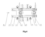
- Fig. 6 shows schematically the structure of a top view of the movable operating platform above water of Fig. 4
- Fig. 7 shows schematically the structure of a left view of the movable operating platform above water of Fig. 4 .
- the movable operating platform above water of the embodiment of the present invention comprises a platform body 11, no less than one wind turbine holding and lifting systems disposed on the upper surface of the platform 11. Driven by drive means, the wind turbine holding and lifting systems are movable longitudinally or transversely along the platform body 11. Wherein, the wind turbine holding and lifting system is described in the aforesaid embodiment and thus will not be described repeatedly.
- the movable operating platform above water of the embodiment the present invention comprises a first wind turbine holding and lifting system 12 and a second wind turbine holding and lifting system 13 at each end of the platform body 11 along a longitudinal direction respectively.
- the first wind turbine holding and lifting system 12 and the second wind turbine holding and lifting system 13 are arranged transversely along the platform body 11.
- a first wind turbine 17 and a second wind turbine 18 are fixed to the first wind turbine holding and lifting system 12 and the second wind turbine holding and lifting system 13 respectively.
- first wind turbine holding and lifting system 12 is described as an example to illustrate the implementation of the present invention.
- the upper surface of the platform 11 is provided with longitudinal guide rails 11-3 extending longitudinally along the platform body 11.
- Guide trays 19 are arranged between the first wind turbine holding and lifting system 12 and the platform body 11.
- the bottom of the guide tray 19 is provided with longitudinal rollers (not shown) fitting with the longitudinal guide rail 11-3.
- the upper surface of the guide tray 19 is provided with transverse guide rails 19-1.
- the bottom surfaces of the first and second legs of the first wind turbine holding and lifting system 12 are provided with transverse rollers fitting with the transverse guide rails 19-1.
- the first wind turbine holding and lifting system 12 is capable of rolling along the transverse guide rails 19-1 of the guide tray 19, and the guide trays 19 carrying the first wind turbine holding and lifting system 12 are capable of rolling along the longitudinal guide rails 11-3.
- the drive means for driving the first wind turbine holding and lifting system 12 to roll along the transverse guide rails 19 may be a drive motor.
- the drive means for drive the guide trays 19 carrying the first wind turbine holding and lifting system 12 to roll along the longitudinal guide rails 11-3 may be a drive motor.
- the drive means for drive the first wind turbine holding and lifting system 12 to roll along the transverse guide rails 19-1 may be a hydraulic cylinder disposed transversely along the platform body 11.
- the hydraulic cylinder By means of the hydraulic cylinder, the first wind turbine holding and lifting system 12 can be stopped and locked at any transverse position.
- the accuracy and safety of transversely rolling of the first wind turbine holding and lifting system 12 are improved.
- the drive means for rolling the guide trays 19 and the first wind turbine holding and lifting system 12 along the longitudinal guide rails 11-3 can be a hydraulic cylinder longitudinally disposed along the platform body 11.
- the first wind turbine holding and lifting system 12 can be stopped and locked at any random longitudinal position, which improves the accuracy and safety of longitudinal roll of the first wind turbine holding and lifting system 12.
- the ends of the platform body 11 are provided with locating grooves for positioning with respect to the wind turbine foundation, said locating grooves being shaped to be adapted with that of the wind turbine foundation. In this way, the ends of the platform body 11 can be positioned accurately with respect to the wind turbine foundation of the wind farm and thus the wind turbine holding and lifting system can be moved accurately to the wind turbine installation site of the wind turbine foundation.
- a first locating groove 11-1 and a second locating groove 11-2 may be provided at two ends of the platform body 11 respectively. If both the first wind turbine holding and lifting system 12 and the second wind turbine holding and lifting system 13 are arranged on the upper surface of the platform body 11, the wind turbines can be positioned accurately with respect to the wind turbine foundations when being installed respectively by the first wind turbine holding and lifting system 12 and the second wind turbine holding and lifting system 13. If only one wind turbine holding and lifting system is arranged on the upper surface of the platform body 11, the wind turbine may be installed from either end of the platform body 11 by means of the wind turbine holding and lifting system and thus facilitate operating the platform body 11.
- the guide tray 19 between the first wind turbine holding and lifting system 12 and the platform body 11 will not be necessary.
- the upper surface of the platform body 11 is provided with longitudinal guide rails extending 1 along the length of the platform body 11.
- the bottom surfaces of the first and second legs of the first wind turbine holding and lifting system 12 are provided with longitudinal rail grooves to fit with the longitudinal guide rails. Driven by drive means, the first wind turbine holding and lifting system 12 is movable along the longitudinal rails.
- two or more draft depth adjusting means 20 are attached to the sides of the platform body 11 and are arranged symmetrically.
- the draft depth adjusting means 20 comprises an airbag 20-4 for adjusting the waterplane area of the platform body; an inflating system 20-1 for controlling the inflation and deflation of the airbag; a telescopic mechanism 20-3 connected to the airbag for controlling the extension and retraction of the airbag; a fixing holder 20-2 for fixing the telescopic mechanism on the platform body.
- a manipulating device of the telescopic mechanism 20-3 is chosen from one of an oil cylinder, an air cylinder or an electrical pushrod.
- the telescopic mechanism 20-3 comprises a plurality of telescopic units connected in series. The telescopic units are extendable and retractable sections in the manner of a parallelogram four-bar mechanism.
- the telescopic mechanism 20-3 retracts such that the airbag 20-4 is kept in a contracted and folded state (as shown in Fig. 11 ), and the platform body 11 navigates at a normal shipping draft depth.
- the operating platform above water can navigate at a high speed.
- the telescopic mechanism 20-3 extends to inflate the airbag 20-4 (as shown in Fig. 11 ) and the airbag contacts with the water surface and becomes a floating box to increase the buoyancy.
- the buoyancy is larger than the weight of the entire operating platform above water so that the platform moves upwardly until the buoyancy equals to the weight of the platform.
- the draft depth of the platform is correspondingly reduced. Since the inflation of the airbag has a large manipulated rage, the waterplane area of the platform body 11 can be increased significantly. Thereby, the draft depth of the ship can be correspondingly reduced extremely small to satisfy the navigation requirements in an offshore shallow zone.
- the platform body 11 is provided with no less than one anchor winches 14 thereon.
- anchor winches 14 which are symmetrically disposed at the sides of the platform body 11.
- the anchor winches coarsely position the platform body 11 longitudinally and transversely in a heaving manner.
- the bottom of the platform body 11 has a flat structure.
- the platform body 11 with a flat bottom structure which is capable of beaching at a shallow water level, makes it possible to use the movable operating platform in an intertidal zone in a muddy coast or a neritic zone.
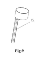
- the sides of the platform body 11 are provided with no less than one bucket legs 15, as shown in Fig. 9 .
- the bucket leg 15 exhibits a reversed barrel structure with its upper end closed and its lower end opened.
- a plurality of bucket legs 15 can be arranged on both sides of the platform body 11.
- platform body lifting means is further arranged to improve the stability of the platform body 11 as well as the resistance to the stormy waves.
- the platform body lifting means is installed on the platform body 11 and the lifting end of the platform body lifting means is connected to the bucket leg 15.
- the platform body 11 is lifted by the platform lifting means to a certain height above the water surface. Thereby the platform body 11 is protected from instability due to the water level changing ensued from the tide difference and the resistance to the stormy waves of the platform body 11 is increased.
- the movable operating platform above water of the present invention may be hauled by a towing ship 16 to the sea area where the wind farm locates, or the movable on-waster operating platform may be provided with a power means to drive the platform to the sea area where the wind farm locates. No limitation upon this is given in the present invention.
- the towing ship 16 conveys the movable operating platform above water to an offshore wind farm.
- the anchor winches 14 anchors and the locating grooves of the platform body 11 is coarsely positioned with respect to the wind turbine foundation in the manner of heaving.
- the flat bottom structure of the platform body 11 beaches is to assure a stable positioning of the platform body 11.
- the plural bucket legs 15 on both sides of the platform body 11 sink into the seabed.
- the height of the platform body 11 above the horizontal plane is increased by means of the platform body lifting means such that the platform body 11 can be stably positioned.
- the platform body 11 can be stabilized merely by heaving.
- the wind turbine lifting device lifts the wind turbine to a target height.
- the wind turbine holding and lifting system is driven to roll to the wind turbine installation position of the wind turbine foundation, the wind turbine holding and lifting system being longitudinally or transversely movable by drive means to precisely position the center of the installation site of the base of the wind turbine tower with respect to that of the wind turbine installation site of the wind turbine foundation.
- the wind turbine and the enclasping means are relatively rotated under a force to precisely position the bolt holes at the bottom of the wind turbine tower with respect to those of the wind turbine foundation.
- the wind turbine is lowered onto the wind turbine foundation by the wind turbine lifting device and is connected therewith via the installation bolts.
- the enclasping means and the wind turbine lifting device is then released, the wind turbine holding and lifting system is removed away from the wind turbine and the movable operating platform above water is removed away from the wind farm. To this end, the installation operation of wind turbines is accomplished.
- the movable operating platform above water with such a structure can fix the wind turbine by means of the wind turbine holding and lifting system, with the wind turbine movable longitudinally or transversely along with the wind turbine holding and lifting system.
- a movable offshore operating platform can not only transport wind turbines, but also serve as the working table for installing the wind turbines.
- the wind turbines are fixed by the wind turbine holding and lifting system and thus are capable of bearing a relatively large wind load.
- the effect that the swinging of the ship body makes the wind turbine swings more severely is reduced due to the relatively low fixing position of the wind turbine.
- the installation part at the bottom of the wind turbine tower can be precisely aligned with that of the wind turbine foundation and thus facilitate the installation.
- the cost for installation is reduced since it is unnecessary to rent a large crane ship.
- the movable operating platform above water is not limited to the draft depth and thus can be applied in wind turbine installation at various sea areas.
- the movable operating platform above water is mainly used in an intertidal zone of a muddy cost, a neritic zone and an abyssal zone.
- the present invention does not place any restriction upon the application area.
- the movable operating platform above water may be also applied in an endorheric river, an inland lake and the like.
Landscapes
- Engineering & Computer Science (AREA)
- Chemical & Material Sciences (AREA)
- Mechanical Engineering (AREA)
- Combustion & Propulsion (AREA)
- Sustainable Energy (AREA)
- Life Sciences & Earth Sciences (AREA)
- Sustainable Development (AREA)
- General Engineering & Computer Science (AREA)
- Architecture (AREA)
- Civil Engineering (AREA)
- Structural Engineering (AREA)
- Ocean & Marine Engineering (AREA)
- Wind Motors (AREA)
- Structures Of Non-Positive Displacement Pumps (AREA)
Applications Claiming Priority (2)
| Application Number | Priority Date | Filing Date | Title |
|---|---|---|---|
| CN200910237988 | 2009-11-27 | ||
| CN2010101121594A CN102079477A (zh) | 2009-11-27 | 2010-02-10 | 一种风机抱举装置及移动式水上作业平台 |
Publications (1)
| Publication Number | Publication Date |
|---|---|
| EP2327880A2 true EP2327880A2 (fr) | 2011-06-01 |
Family
ID=42224602
Family Applications (1)
| Application Number | Title | Priority Date | Filing Date |
|---|---|---|---|
| EP10290151A Withdrawn EP2327880A2 (fr) | 2009-11-27 | 2010-03-22 | Système de rétention et d'élévation d'éolienne et plateforme d'exploitation mobile au-dessus de l'eau |
Country Status (4)
| Country | Link |
|---|---|
| US (1) | US20110129334A1 (fr) |
| EP (1) | EP2327880A2 (fr) |
| JP (1) | JP2011112044A (fr) |
| CN (1) | CN102079477A (fr) |
Cited By (3)
| Publication number | Priority date | Publication date | Assignee | Title |
|---|---|---|---|---|
| GB2479232A (en) * | 2010-03-10 | 2011-10-05 | Stewart Willis | Transporting structures, eg offshore structures, eg wind turbines |
| CN103910041A (zh) * | 2014-04-03 | 2014-07-09 | 上海振华重工启东海洋工程股份有限公司 | 高精度海上风机吊装船 |
| CN118273886A (zh) * | 2024-06-03 | 2024-07-02 | 威海德创船舶技术有限公司 | 一种风电船桁架 |
Families Citing this family (40)
| Publication number | Priority date | Publication date | Assignee | Title |
|---|---|---|---|---|
| ES2444436T3 (es) * | 2010-10-01 | 2014-02-25 | Nordic Yards Holding Gmbh | Barco y procedimiento para transportar y colocar estructuras offshore |
| JP2012112370A (ja) * | 2010-11-05 | 2012-06-14 | Mitsubishi Heavy Ind Ltd | 洋上風車設置用船舶およびこれを用いた洋上風車設置方法 |
| JP2012107585A (ja) * | 2010-11-18 | 2012-06-07 | Mitsubishi Heavy Ind Ltd | 洋上風車設置用船舶およびこれを用いた洋上風車設置方法 |
| JP5383631B2 (ja) | 2010-11-18 | 2014-01-08 | 三菱重工業株式会社 | 洋上風車設置用船舶およびこれを用いた洋上風車設置方法 |
| CN102616339B (zh) * | 2011-01-30 | 2014-10-29 | 华锐风电科技(江苏)有限公司 | 一种风电机组的运输安装船及风电机组的船运和安装方法 |
| CN102344103A (zh) * | 2011-08-24 | 2012-02-08 | 三一电气有限责任公司 | 一种风机的护持装置及风机抱举机构 |
| CN102502422B (zh) * | 2011-09-23 | 2014-01-15 | 三一电气有限责任公司 | 一种海上风机整体吊装设备 |
| DK2586933T3 (en) * | 2011-10-24 | 2015-12-21 | Areva Wind Gmbh | Work platforms for an offshore wind power plant |
| JP5791540B2 (ja) * | 2012-02-20 | 2015-10-07 | 三菱重工業株式会社 | 洋上風車設置用船舶および洋上風車設置方法 |
| EP2669238B1 (fr) * | 2012-06-01 | 2016-12-14 | Siemens Aktiengesellschaft | Manipulation facilitée de pales d'éolienne |
| US9145830B2 (en) | 2012-06-04 | 2015-09-29 | United Technologies Corporation | Turbomachine geared architecture support assembly |
| DK177683B1 (en) * | 2012-08-30 | 2014-03-03 | Envision Energy Denmark Aps | Method of installing an offshore wind turbine and a transport vessel thereof |
| NL2009763C2 (en) * | 2012-11-06 | 2014-05-08 | Mecal Wind Turbine Design B V | Floatable transportation and installation structure for transportation and installation of a floating wind turbine, a floating wind turbine and method for transportation and installation of the same. |
| KR101439520B1 (ko) * | 2013-05-31 | 2014-09-05 | 이레엔지니어링(주) | 해상 풍력발전기 설치용 작업선 |
| WO2014193172A1 (fr) * | 2013-05-31 | 2014-12-04 | 이레엔지니어링 주식회사 | Appareil d'installation de pieu marin |
| FR3012410B1 (fr) * | 2013-10-28 | 2016-01-01 | Technip France | Structure de transport et d'installation d'au moins un ensemble structurel dans une etendue d'eau, installation et procede associes |
| CN103693170A (zh) * | 2013-12-10 | 2014-04-02 | 广东明阳风电产业集团有限公司 | 一种漂浮式海上风电组装平台及用该平台组装海上风机的方法 |
| CN103921900B (zh) * | 2014-01-31 | 2017-10-10 | 中交一航局第二工程有限公司 | 母子双浮体海上风力发电机组整体运输安装一体船的施工方法 |
| CN103807116B (zh) * | 2014-01-31 | 2018-06-08 | 中交一航局第二工程有限公司 | 海上风力发电机组拉索千斤顶提升安装装置及施工方法 |
| CN103803024A (zh) * | 2014-01-31 | 2014-05-21 | 中交一航局第二工程有限公司 | 半浮式海上风力发电机组整体运输安装一体船及施工方法 |
| CN103850891B (zh) * | 2014-02-27 | 2016-08-17 | 北京金风科创风电设备有限公司 | 风机塔架的构件的对接装置及方法、平移机构及静止机构 |
| CN105253260B (zh) * | 2015-10-27 | 2020-03-06 | 纳路易爱姆斯株式会社 | 前方搭载式塔柱姿势控制海上风力发电机安装专用船舶 |
| CN105736249B (zh) * | 2016-01-28 | 2018-12-18 | 中交第三航务工程局有限公司宁波分公司 | 风电机组和承载该风电机组的运输船及吊装方法 |
| CN105715464B (zh) * | 2016-01-28 | 2018-12-18 | 中交第三航务工程局有限公司宁波分公司 | 风电机组的吊装方法 |
| JP2019532220A (ja) * | 2016-09-02 | 2019-11-07 | ナショナル オイルウェル ヴァーコ ノルウェー アーエス | 洋上風車建設方法 |
| GB2561612B (en) * | 2017-04-21 | 2019-10-16 | Sense Wind Ltd | Method for assembling a wind turbine and a wind turbine system |
| CN108791715A (zh) * | 2018-06-07 | 2018-11-13 | 上海交通大学 | 一种超大型浮体浅水定位系统 |
| CN109209786B (zh) * | 2018-11-29 | 2019-10-29 | 绍兴市亚索新能源科技有限公司 | 一种风力发电机组故障检测方法 |
| CN109268211B (zh) * | 2018-11-29 | 2019-10-11 | 河北思达歌数据科技投资有限公司 | 一种自适应风力发电装置 |
| CN109469061B (zh) * | 2018-12-19 | 2024-03-29 | 南通振华重型装备制造有限公司 | 一种风电安装平台用抱桩器 |
| CN112078734A (zh) * | 2019-06-14 | 2020-12-15 | 韩国电力公社 | 用于运输和安装海上风力发电机的船舶 |
| NL2023699B1 (en) | 2019-08-23 | 2021-05-04 | Delft Offshore Turbine B V | System for transporting an offshore structure |
| CN110775215B (zh) * | 2019-12-04 | 2023-06-16 | 海南大学 | 一种半潜平台-风力机双体模块化浮式集成系统及其使用方法 |
| CN110758663B (zh) * | 2019-12-04 | 2023-06-16 | 海南大学 | 一种张力腿平台-风力机双体模块化浮式集成系统及其使用方法 |
| CN113023095B (zh) * | 2019-12-24 | 2022-09-23 | 江苏金风科技有限公司 | 海上风电安装船用塔筒固定装置及塔筒运输工装 |
| CN112722184A (zh) * | 2020-12-29 | 2021-04-30 | 广东精铟海洋工程股份有限公司 | 一种运维船补偿夹持器 |
| CN113404648B (zh) * | 2021-06-16 | 2023-02-28 | 海洋石油工程股份有限公司 | 一种海上风机整体快速浮装方法 |
| US12584461B2 (en) * | 2022-09-08 | 2026-03-24 | Jason C. FABRE | Floating offshore wind turbine apparatus and installation method |
| CN115595878A (zh) * | 2022-10-18 | 2023-01-13 | 中交第一航务工程局有限公司(Cn) | 一种可自动升降、快速平移水上操作平台及其施工方法 |
| KR20250094181A (ko) * | 2023-12-18 | 2025-06-25 | 현대자동차주식회사 | 풍력 발전 시스템을 구비하는 수직 이착륙장 |
Family Cites Families (13)
| Publication number | Priority date | Publication date | Assignee | Title |
|---|---|---|---|---|
| CA1061191A (fr) * | 1976-01-12 | 1979-08-28 | Sigurdur Ingvason | Plate-forme de radoub de bateaux |
| NL8800664A (nl) * | 1988-03-17 | 1989-10-16 | Darya Paye Jetty Co Ltd | Werkwijze en inrichting voor het vervaardigen van een waterbouwkundige constructie, zoals een pijler, steiger en dergelijke. |
| US6523491B1 (en) * | 1999-11-12 | 2003-02-25 | Textron Inc. | Lift boat |
| NO315112B1 (no) * | 2001-10-17 | 2003-07-14 | Jan Vatsvaag | Offshore löftekonstruksjon for löfting av understell på offshore-installasjoner samt en fremgangsmåte for heving av slike |
| GB2394498B (en) * | 2002-10-23 | 2006-08-09 | Engineering Business Ltd | Mounting of offshore structures |
| FR2849877B1 (fr) * | 2003-01-09 | 2005-12-16 | Saipem Sa | Procede d'installation en mer d'une eolienne |
| US7234409B2 (en) * | 2003-04-04 | 2007-06-26 | Logima V/Svend Erik Hansen | Vessel for transporting wind turbines, methods of moving a wind turbine, and a wind turbine for an off-shore wind farm |
| US7112010B1 (en) * | 2003-12-10 | 2006-09-26 | William Clyde Geiger | Apparatus, systems and methods for erecting an offshore wind turbine assembly |
| US20080199259A1 (en) * | 2007-02-21 | 2008-08-21 | Cannon James R | Marine pile driving and boring apparatus |
| FR2923454B1 (fr) * | 2007-11-09 | 2010-01-15 | Freyssinet | Procede de transport en milieu aquatique d'un ouvrage civil |
| CA2710058C (fr) * | 2007-12-21 | 2016-04-19 | Vestas Wind Systems A/S | Procede d'installation d'une eolienne en mer et systeme de barge |
| US20090217852A1 (en) * | 2008-02-29 | 2009-09-03 | Winergy Llc | Method and apparatus for transporting and mounting offshore wind generators |
| ES2358032B1 (es) * | 2008-12-17 | 2011-12-30 | Manuel Torres Martínez | Base de cimentación para el montaje de aerogeneradores en lecho acuático y método de fabricación de dicha cimentación. |
-
2010
- 2010-02-10 CN CN2010101121594A patent/CN102079477A/zh active Pending
- 2010-03-22 EP EP10290151A patent/EP2327880A2/fr not_active Withdrawn
- 2010-03-23 US US12/729,803 patent/US20110129334A1/en not_active Abandoned
- 2010-03-26 JP JP2010071615A patent/JP2011112044A/ja not_active Withdrawn
Non-Patent Citations (1)
| Title |
|---|
| None |
Cited By (4)
| Publication number | Priority date | Publication date | Assignee | Title |
|---|---|---|---|---|
| GB2479232A (en) * | 2010-03-10 | 2011-10-05 | Stewart Willis | Transporting structures, eg offshore structures, eg wind turbines |
| GB2479232B (en) * | 2010-03-10 | 2017-04-19 | W3G Shipping Ltd | Offshore structures and associated apparatus and methods |
| CN103910041A (zh) * | 2014-04-03 | 2014-07-09 | 上海振华重工启东海洋工程股份有限公司 | 高精度海上风机吊装船 |
| CN118273886A (zh) * | 2024-06-03 | 2024-07-02 | 威海德创船舶技术有限公司 | 一种风电船桁架 |
Also Published As
| Publication number | Publication date |
|---|---|
| US20110129334A1 (en) | 2011-06-02 |
| CN102079477A (zh) | 2011-06-01 |
| JP2011112044A (ja) | 2011-06-09 |
Similar Documents
| Publication | Publication Date | Title |
|---|---|---|
| EP2327880A2 (fr) | Système de rétention et d'élévation d'éolienne et plateforme d'exploitation mobile au-dessus de l'eau | |
| EP2327874A2 (fr) | Système de support et de levage d'une éolienne et plateforme d'opérations mobile | |
| US11560277B2 (en) | Method of securing and transferring a load between a vessel and an offshore installation and an apparatus therefor | |
| US8701579B2 (en) | Offshore wind turbine installation | |
| EP2724021B1 (fr) | Navire d'installation de parc éolien offshore autonome, et procédé d'installation utilisé lors de la construction d'un parc éolien offshore | |
| EP3947823B1 (fr) | Procédé de sécurisation et de transfert d'une charge entre un navire et une installation en mer et appareil associé | |
| GB2560057B (en) | Turbine deployment system | |
| CN204473079U (zh) | 海上风机整机运输与安装专用船 | |
| CN104527937A (zh) | 海上风机整机运输与安装专用船及方法 | |
| US20240217782A1 (en) | Upend crane and installation vessel | |
| KR101297669B1 (ko) | 해상풍력발전기 설치 전용선을 이용한 해상풍력발전기 설치방법 | |
| NL2031010B1 (en) | A method and system of installing a floating foundation, assembly of floating foundation and ballasting frame, and ballasting frame |
Legal Events
| Date | Code | Title | Description |
|---|---|---|---|
| PUAI | Public reference made under article 153(3) epc to a published international application that has entered the european phase |
Free format text: ORIGINAL CODE: 0009012 |
|
| AK | Designated contracting states |
Kind code of ref document: A2 Designated state(s): AT BE BG CH CY CZ DE DK EE ES FI FR GB GR HR HU IE IS IT LI LT LU LV MC MK MT NL NO PL PT RO SE SI SK SM TR |
|
| AX | Request for extension of the european patent |
Extension state: AL BA ME RS |
|
| STAA | Information on the status of an ep patent application or granted ep patent |
Free format text: STATUS: THE APPLICATION IS DEEMED TO BE WITHDRAWN |
|
| 18D | Application deemed to be withdrawn |
Effective date: 20131001 |