EP2328045A1 - Horloge - Google Patents
Horloge Download PDFInfo
- Publication number
- EP2328045A1 EP2328045A1 EP10015047A EP10015047A EP2328045A1 EP 2328045 A1 EP2328045 A1 EP 2328045A1 EP 10015047 A EP10015047 A EP 10015047A EP 10015047 A EP10015047 A EP 10015047A EP 2328045 A1 EP2328045 A1 EP 2328045A1
- Authority
- EP
- European Patent Office
- Prior art keywords
- housing
- dial
- fastening means
- clock
- movement
- Prior art date
- Legal status (The legal status is an assumption and is not a legal conclusion. Google has not performed a legal analysis and makes no representation as to the accuracy of the status listed.)
- Granted
Links
Images


Classifications
-
- G—PHYSICS
- G04—HOROLOGY
- G04B—MECHANICALLY-DRIVEN CLOCKS OR WATCHES; MECHANICAL PARTS OF CLOCKS OR WATCHES IN GENERAL; TIME PIECES USING THE POSITION OF THE SUN, MOON OR STARS
- G04B37/00—Cases
- G04B37/08—Hermetic sealing of openings, joints, passages or slits
- G04B37/081—Complete encasings for wrist or pocket watches also comprising means for hermetic sealing of the winding stem and crown
Definitions
- the invention relates to a timepiece having the features of the preamble of claim 1.
- the dial is deliberately pressed against a part of the watch case as a supporting part.
- the dial is disposed therein in the watch case and abuts in an abutment position on the housing.
- tabs are used, which are bolted to a motherboard of the movement and laterally supported on the outside of the watch case.
- the tabs are relatively small and thin compared to the rest of the movement and are constantly under tension. This leads to a risk of wear and breakage of the tabs.
- material wear or material breakage may occur during wear when the movement is fastened by means of such tabs.
- flaps break unforeseen even in watches that are not exposed to any special stress. For these reasons, those tabs are usually replaced preventively against new tabs when the watch is serviced.
- the tabs are usually screwed by means of small screws on the clockwork. It can sometimes lead to a fracture of the screw in the motherboard of the movement provided thread, so that such a screw drilled out, and the thread must be recut. In unfavorable cases, a completely new master plate must be used for the movement, if a drilling out of the screw and a re-cutting of the thread is not possible. This leads to a very high cost and time.
- the invention has for its object to provide a clock of the type mentioned, which improves the attachment of the dial and the movement within the watch case despite a simple construction, and allows easy and safe installation.
- the object is achieved by a generic watch in which a separately formed to the housing cover with the housing engaged fastening means in the contact position determines the dial relative to the housing.
- the fastener can set in this way the dial and the associated movement in the housing before the separately formed housing cover is connected to the housing to close it.
- the pressure of the dial to the housing can be fixed in this way regardless of the separate housing cover, so that the damage of the dial is less likely, but the dial is still sufficiently firmly held in the housing. Due to the separate design of fastener and housing cover, it may be possible to first set the dial by means of the fastener in the housing before the housing cover is placed on the housing. This may allow to observe the dial and other components during mounting.
- the fastener may be rotatable from a released, the dial releasing position in a fixed position in which the dial is held in the contact position. In this way, a simple mounting of the fastener can be made possible.
- the fastening means may surround at least a part of the movement in an annular manner and be rotatable relative to the movement and the dial.
- the space between the movement and the housing can be efficiently used in this way.
- the fastening means can engage in the housing by means of a thread.
- the fastener can be easily attached to the housing by means of the thread and possibly loosened therefrom again, in order to allow maintenance or repair.
- the engagement between the housing and the fastening means comprise a recessed connection or a bayonet-type connection.
- Reverse connections or bayonet-type connections are easy to provide between the housing and the fastening means.
- such types of connection can be easily solved by pressing and turning, and fixed again.
- the engagement between the housing and the fastening means may comprise a latching closure.
- a latching closure This can be advantageous if, for example, the possibility of an independent release of the fastening means is to be reduced.
- a snap lock can give a well-perceptible feedback that the fastener has reached a fastened position.
- At least one rod-like structure may be provided on the clock, which protrudes through the housing into the movement, and the fastening means is arranged in the contact position between the dial and the rod-like structure.
- a rod-like structure may be, for example, an elevator shaft, which is connected to an externally mounted crown.
- a push rod may be provided, which transmits a pressure movement on an outside push button in the movement.
- At least one rod-like structure may be provided on the watch which protrudes through the housing into the movement, and the fastening means may be arranged in the fastened position on a side of the rod-like structure facing away from the dial.
- the rod-like structure can thus be passed easily past the fastening means in order to project into the movement. This can simplify the internal structure of the clock.
- At least one rod-like structure may be provided on the watch, which protrudes through the housing into the movement, wherein at least part of the fastening element at least partially surrounds the rod-like structure.
- the rod-like structure can thereby at least partially penetrate the fastening element. In this way, the fastener can be made relatively thick and stable and the rod-like structure can still be performed in the movement.
- a contact pressure transmission means can be arranged between the dial and the fastening means.
- a pressure transmitting means may in this way act as a kind of spacer, so that the fastening means is arranged spaced from the dial, if this is advantageous for the arrangement of the components in the clock.
- the fastening means and / or the Anyakübertragungsstoff may be formed annular. This can equalize the pressure on the dial and thus reduce the risk of damage to the dial when attaching the fastener. Furthermore, a ring-like design of the fastener and / or the Anyakübertragungsffens simplify the preparation of these means.
- the pressure-transmitting means may be held in a fixed position of the fastening means under resilient bias.
- the dial can be held securely in the housing and the likelihood of self-loosening of the fastener can be easily reduced.
- the contact pressure transmission means may be formed resiliently yielding.
- a resilient bias can be built by deforming the Anyakübertragungsstoffs to keep the dial safely in the housing. Due to the resiliently yielding design of the pressure-transmitting means, a compliance for the resilient bias can be easily adjusted.
- the contact pressure transmission means and / or the fastening means may have an interruption, which releases a passage for a rod-like structure in the contact position or the fixed position, which protrudes through the housing into the movement.
- This can be a particularly simple design, which allows the passage of a rod-like structure in the movement. Such a design can simplify the manufacture of the pressure-transmitting means or the fastening means.
- At least one resilient clamping means may be provided between the dial and the pressure-transmitting means and / or between the pressure-transmitting means and the fastening means, which means the fastening means biased in the fastened position relative to the dial.
- the tensioning means can at least partially surround the movement in the fastened position.
- the available space between the movement and the housing can be used well and efficiently.
- the clamping element may have at least one portion which is in engagement with the movement, and additionally sets the movement in relation to the housing in the contact position or biases it into the contact position.
- an additional holding force can be exerted on the movement in order to better hold the movement in the housing.
- recesses can be used in addition to a clockwork for holding, which would otherwise be occupied by conventional retaining tabs, so that any bungs therein can be covered.
- the dial can be provided against rotation relative to the housing.
- the dial can thus be brought to a defined position during assembly, which it maintains during the subsequent mounting of the fastener, in particular when the fastener is rotatable to a fixed position and the rotation is partially transmitted to the dial.
- the dial can be provided by an engagement with respect to the housing rotationally. This can simplify the assembly of the clock according to the invention.
- projections may be provided on the housing or dial which engage recesses on the dial or housing. This can simplify mounting of the dial as it maintains its alignment with the housing.
- the contact pressure transmission means in particular by an intervention, is provided rotationally fixed relative to the housing.
- the contact pressure transmission means in particular by an intervention, is provided rotationally fixed relative to the housing.
- the fastening means and / or the housing cover could be screwed into the housing in the fastened position. This can allow a simple and uncomplicated installation.
- At least one internal thread can be provided in the interior space, into which both the fastening means and the housing cover can be screwed.
- Such an embodiment allows to easily provide an engagement of the fastener in the housing and the housing cover in the housing. Possibly even the fastening means can be screwed into the same thread, in which the housing cover is also screwed.
- the fastening means a first threaded portion having a first nominal diameter, and a second threaded portion having a second nominal diameter for the housing cover. This may allow the size of the dial to be chosen independently of the size of the case cover, and hence the case dimensions and dial dimensions to be varied substantially independently of each other.
- the housing cover can be screwed into an internal thread of the housing, and be provided in the internal thread at least one omission, in which the fastening means can be latched.
- the advantages of a screwed-housing cover, as well as the advantages of a fastener to be locked can be combined.
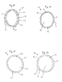
- FIG. 1 shows a first embodiment of the clock 1 according to the invention in a schematic sectional exploded view.
- the clock 1 has a housing 2, in which the movement 3 can be arranged, wherein the movement 3 is connected to a dial 4.
- On a front side 5 of the dial 4 at least one pointer 6 is arranged, which is operatively connected to the movement 3.
- the movement 3 is arranged on a rear side 7 of the dial 4.
- On a back 8 of the movement 3, a flywheel 9 may be arranged, which can operate, for example, an automatic elevator of a mechanical movement.
- a receiving opening 11 is further provided on a peripheral peripheral side 10, in which an optional rod-like structure 12 can protrude.
- the rod-like structure 12 is preferably connected to a crown 13 and may form approximately an elevator shaft or the extension of a push button. However, it is also possible to use movements 3 without a rod-like structure or with a plurality of rod-like structures. It is also possible to use electrically operated or electronic movements instead of a mechanical movement.
- a socket portion 15 with a receiving opening 16 forms part of a holder for a watch glass 17.
- a bezel 19 may be provided on the socket portion 15.
- An outer peripheral side 18 of the socket portion 15 may be offset from the other housing 2 and made narrower to accommodate such optional bezel 19 thereon.
- an interior 20 is provided, which may be formed in this example as a cylindrical bore. At least part of an inner cylindrical surface 21 of the inner space 20 is provided with an internal thread 22 in this embodiment. At a the socket portion 15 facing the end of the interior 20, a shoulder 23 is formed.
- the clock 1 also has a fastening means 24.
- this is formed as a ring with an external thread 25 which is provided on an outer periphery of the fastening means 24.
- the fastening means 24 further comprises a plurality, but at least one omission 26, which can be at least partially penetrated by the rod-like structure 12 in a fastened position, or at least partially surround the rod-like structure 12.
- the external thread 25 is formed so that it can be screwed into the internal thread 22 of the housing 2.
- the fastening means 24 is in FIG. 1 shown in a released position in which the dial 4 is released, so to speak.
- a housing cover 27 with an annular projection 28 is provided to close the inner space 20 at a rear side 29 of the housing 2.
- an external thread 30 is formed, which is screwed into the internal thread 22 of the housing 2.
- the housing cover 27 has an annular projection 28 adjacent flange 31, which abuts in a fixed position on the back 29 of the housing 2. Between the flange 31 and the housing 2 may possibly be provided a sealing element. It is also conceivable in all embodiments to provide in the interior 20 a shoulder and a second internal thread, which has a larger nominal diameter, than the nominal diameter of the region of the inner space or the internal thread, in which the fastening means 24 is provided. In such a larger internal thread then the housing cover 27 may be provided.
- FIG. 2 shows the exemplary embodiment of the clock FIG. 1 but assembled and in the fastened position in which the fastener 24 is mounted in the housing 2.
- the dial 4 rests against the shoulder 23 of the housing 2 within the interior space 20 and thus is in an abutment position.
- the fastening means 24 is screwed into the internal thread 22 of the inner cylindrical surface 21, is in this case on the dial 4, so that the dial 4 is fixed relative to the housing 2.
- the housing cover 27 closes the inner space 20 on one side of the housing 2, in this case on the rear side 29 of the housing 2.
- the watch glass 17 is received in the receiving opening 16 of the socket portion 15 and fixed therein.
- the optional bezel 19 is mounted on the socket portion 15 and surrounds it laterally and partially on a front side 32 of the housing 2.
- FIG. 3 shows a second exemplary embodiment of a clock, wherein in addition to the fastening means 24 a pressure transmission means 33 between the dial 4 and the fastening means 24 is provided.
- the pressure transmission means 33 which separately in the FIG. 7 is again shown, is approximately annular and here has at least one projection 34, as well as an executed as an interruption omission 35 for a rod-like structure 12. Instead of an interruption, a bore or taper can also be provided.
- the fastening means 24 and the pressure-transmitting means 33 can also be designed so that they are arranged in the fastened position between the dial 4 and the rod-like structure 12, so that both means can be carried out continuously.
- the dial 4 may be rotatably formed in all the embodiments described herein opposite to the housing 2, such as by the provision of a nose 51 which can engage in the housing 2. It is also conceivable that a part of the housing 2 engages the dial 4, or that the dial 4 is held in a rotationally fixed manner at its shoulder 23 in a form-fitting manner.
- the pressure-transmitting means 33 In the fastened position, the pressure-transmitting means 33 is held under spring bias between the fastening means 24 and the dial 4, wherein at least one of said components is designed to be prestressed for this purpose.
- the pressure transmitting means 33 may be resiliently designed to be biased in the fastened position relative to the dial 4.
- the disclosed watch may be, in particular, a wristwatch with a wrist band connection portion 37.
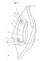
- FIG. 4 shows a schematic exploded perspective view of the second exemplary embodiment, looking substantially at the back 29 of the housing 2. It can be seen that the lugs 34 arranged at an angular distance of approximately 90 ° on the contact pressure transmission means 33 will engage in the identically arranged guide grooves 36 on the housing 2 when the clock 1 is assembled.
- the guide grooves 36 are also arranged at an angular distance of approximately 90 ° to the receiving opening 11 of the housing 2.
- FIG. 5 shows a further, third exemplary embodiment of the invention, in addition to the previously described embodiments, a clamping means 38 provides.
- the tensioning means 38 can, as in FIG. 5 shown, between the fastening means 24 and the Anvikübertragungsstoff 33 may be arranged, but also conceivable between the An fürübertragungsstoff 33 and the dial 4.
- the clamping means 38 is resilient and may be about a spring ring by means of which a resilient bias in the fastened position can be applied , One possible embodiment of such a ring is in the FIGS. 15 and 16 shown. In the FIGS. 15 and 16 a clamping means 38 is shown, which is designed as a kind of spring ring.
- the ring is constructed of a number of arcuate portions 49, which are connected to each other at the bow ends 50.
- the bow ends 50 can serve in the fastened position as a bearing surface for the fastening means 24, the pressure transmission means 33 or the dial 4, wherein the arcuate sections 49 serve as a support for the corresponding opposite fastening means 24, Anlichübertragungsstoff 33 or dial 4.
- clamping means 38 may additionally comprise at least one projection 40 which presses the movement 3 in the direction of paragraph 23 in a fixed position.
- at least one corresponding recess 39 may be provided, in which the at least one projection 40 can engage. This can provide additional stability of the dial 4 and the movement attached thereto.
- an exemplary fastener 24 is shown which may be used in particular in the first embodiment shown above.
- at least one planar flange surface 41 may be provided on the fastening means 24 in order to ensure as uniform a pressure as possible on the underlying elements.
- tool engagements 42 are provided, in which a part of a tool can be used to release the fastener. These tool engagements may be formed as a blind hole or through hole, but need not be cylindrical.
- the fastener in FIG. 6 is annular and has an inner bore 43 to receive components such as the movement 3 in the mounted position. Such an inner bore 43 may also preferably be present on the pressure-transmitting transmission means 33 and the tensioning means 38 if they are of annular design.
- FIG. 7 shows a variant of a pressure transmission means 33, which can be used in particular in the second exemplary embodiment and a fourth embodiment shown below.
- FIG. 8 shows an alternative fastening means 24 associated with the embodiment shown in FIG. 14 ,
- the fastening means has, instead of an external thread 25, at least one locking lug 44, which points radially outward.
- FIG. 9 shows a clamping means 38, which in this example has at least two lugs 40, which are formed pointing radially inwards to engage in a movement.
- FIG. 10 shows a fastening means 24 in which provided on a jacket-shaped outer surface 45 slot-like omissions 26 through which approximately a rod-like structure 12 can protrude in a fixed position.
- FIG. 10 shows a plurality of omissions 26, which are arranged radially over the circumference of the annular fastening means 24. In this way, a plurality of rod-like structures 12 may penetrate the fastener 24 simultaneously in different directions and / or the fastener may be rotated to different positions to still provide a passageway for the rod-like structure 12.
- fastening means 24 also has a plurality of omissions 26.
- the fastener 24 in the FIG. 11 from the fastener of the FIG. 10 derived.
- the FIG. 11 can be understood that the fastener from the FIG. 10 sliced or halved along a peripheral side. This can be used to accommodate the fastener in smaller receiving openings 11 of a housing 2.
- the fastener from the FIG. 10 In particular, it may be used to mechanically tighten the fastener 24.
- fastening means 24 is formed particularly flat. This may be required, the fastener 24 between a rod-like structure 12 and the dial 4 should be arranged in the fastened position. Alternatively, it may be necessary that the fastening means 24 is formed particularly flat when a pressure transmission means 33 and / or an additional tensioning means 38 are provided in the clock 1.
- fastening means 24 is formed as a broken ring, in which the omission 26 forms the interruption of the ring.
- the rod-like structure 12 is guided in the fastened position.
- an external thread 25 is provided on the outside circumferentially.
- FIG. 14 a fourth exemplary embodiment is shown schematically in a perspective view.
- a kind of hinge connection / bayonet connection or latching closure is provided in this embodiment by which the fastening means 24 can be connected to the housing 2.
- a fastener is conveniently used, which is approximately in FIG. 8 is shown and has at least one locking lug 44.
- latching structures 46 are formed on the housing 2.
- the housing cover 27 can then be fastened to the housing 2 separately from the fastening means 24, wherein both a threaded connection, a previously described hinge connection / bayonet connection, latching closure or other connections are conceivable.
- the at least one latching structure 46 has a groove section 47 which extends approximately transversely to the guide groove 36 and into which a locking projection 44 of the fastening means 24 can be inserted.
- an additional undercut 48 may be present, in which a locking lug 44 can be latched. In this way, the latching structure 46 together with the fastening means 24 form a kind of latching or latching connection.
- the groove portion 47 and the additional providable undercut 48 may also be arcuate, so that the fastening means 24 form a kind of recessed connection or bayonet connection in the latching structure 46.
- fastener 24 may also be an additional snap-in structure that locks the fastener 24 in the fastened position.
- the receiving opening 11 has a continuous diameter, in which the fastening means 24 and the housing cover 27 are attached.
- the receiving space 11 may also be formed stepped, so that the outer diameter of the fastening means 24 and the housing cover 27 and its annular projection 28 may differ.
- the fastening means 24 may generally be provided in all embodiments of different materials and in different embodiments.
- the fastener may be made of a metal such as gold or platinum to serve as a carrier for decorations such as gems or engravings.
- the fastener could also be made of carbon or titanium to save weight.
- the assembly with the dial 4 and the movement 3 attached thereto from the back 29 of the housing 2 ago in the interior 20 of the housing 2 is inserted, so that the front side 5 of the dial 4 rests against the shoulder 23 of the housing 2 in the contact position.
- the fastening means 24 is then screwed into the housing 2, wherein the external thread 25 of the fastening means 24 engages in the internal thread 22 in the inner space 20.
- the fastening means 24 is screwed in until the flange 41 on the dial 4, that is resting on the back 7, and the dial 4 relative to the housing 2 determines. In this case, the dial 4 is pressed against the shoulder 23.
- the crown 13 is guided with the projecting rod-like structure 12, for example, an elevator shaft through the omission 14 in the housing 2 in the receiving opening 11 on the movement 3 and fixed in the movement 3.
- the housing cover 27 is also screwed into the internal thread 22 of the housing 2.
- a previously mentioned second internal thread could be provided on the housing 2, into which the housing cover 27 can be detachably screwed.
- the pressure-transmitting transmission means 33 and / or the tensioning means 38 are first placed on the dial 4 arranged in the housing 2.
- the pressure transmission means 33 and / or the tensioning means 38 surround the movement 3 at least partially. Subsequently, the fastening means 24 is mounted engaging in the housing 2.
- FIG. 14 instead of the threaded connection can also in FIG. 14 be shown locking connection or a recessed joint given as long as the housing 2 and the fastening means 24 engage.
- the screwing of the fastener 24 is replaced by an insertion of the locking lugs 44 in the guide grooves on the housing 2, followed by a rotation of the fastener 24 until each locking lug 44 is inserted through the corresponding groove portion 47 in the latching structure 46 and in the undercut 48th locks.
- Also provided on the dial 4 nose 51 can counteract the rotational movement of the fastener 24 by engaging with the housing 2.
Landscapes
- Physics & Mathematics (AREA)
- General Physics & Mathematics (AREA)
- Electric Clocks (AREA)
- Electromechanical Clocks (AREA)
Applications Claiming Priority (1)
| Application Number | Priority Date | Filing Date | Title |
|---|---|---|---|
| DE200920016242 DE202009016242U1 (de) | 2009-11-27 | 2009-11-27 | Uhr |
Publications (2)
| Publication Number | Publication Date |
|---|---|
| EP2328045A1 true EP2328045A1 (fr) | 2011-06-01 |
| EP2328045B1 EP2328045B1 (fr) | 2013-01-16 |
Family
ID=43629482
Family Applications (1)
| Application Number | Title | Priority Date | Filing Date |
|---|---|---|---|
| EP10015047A Active EP2328045B1 (fr) | 2009-11-27 | 2010-11-26 | Horloge |
Country Status (2)
| Country | Link |
|---|---|
| EP (1) | EP2328045B1 (fr) |
| DE (1) | DE202009016242U1 (fr) |
Citations (7)
| Publication number | Priority date | Publication date | Assignee | Title |
|---|---|---|---|---|
| CH224252A (fr) * | 1942-02-03 | 1942-11-15 | Boites La Centrale Fab De | Boîte de montre étanche. |
| CH241709A (de) * | 1944-08-25 | 1946-03-31 | Steimann Hans | Uhr mit zweiteiliger Aufzugwelle. |
| DE1214161B (de) * | 1954-11-22 | 1966-04-07 | Piquerez Sa Ervin | Dichtes Uhrengehaeuse |
| EP0400449A1 (fr) * | 1989-05-29 | 1990-12-05 | Eta SA Fabriques d'Ebauches | Pièce d'horlogerie à habillement simplifié |
| EP0430113A1 (fr) * | 1989-11-30 | 1991-06-05 | Tissot S.A. | Boîte de montre pour montage automatisé |
| DE102005043085A1 (de) * | 2005-08-24 | 2007-03-01 | Carsten Hellmann | Uhrgehäuse für eine Armbanduhr |
| EP1970779A1 (fr) * | 2007-03-16 | 2008-09-17 | Richemont International S.A. | Montre et procédé d'emboîtement |
Family Cites Families (3)
| Publication number | Priority date | Publication date | Assignee | Title |
|---|---|---|---|---|
| CH285844A (fr) * | 1950-07-10 | 1952-09-30 | Lang Louis Sa | Pièce d'horlogerie. |
| DE1684812U (de) * | 1952-09-25 | 1954-10-14 | Richard Pfisterer | Stosssichere uhr. |
| CH312657A (fr) * | 1953-12-14 | 1956-02-15 | C R Spillmann & Cie Sa | Boîter de montre |
-
2009
- 2009-11-27 DE DE200920016242 patent/DE202009016242U1/de not_active Expired - Lifetime
-
2010
- 2010-11-26 EP EP10015047A patent/EP2328045B1/fr active Active
Patent Citations (8)
| Publication number | Priority date | Publication date | Assignee | Title |
|---|---|---|---|---|
| CH224252A (fr) * | 1942-02-03 | 1942-11-15 | Boites La Centrale Fab De | Boîte de montre étanche. |
| CH241709A (de) * | 1944-08-25 | 1946-03-31 | Steimann Hans | Uhr mit zweiteiliger Aufzugwelle. |
| DE1214161B (de) * | 1954-11-22 | 1966-04-07 | Piquerez Sa Ervin | Dichtes Uhrengehaeuse |
| EP0400449A1 (fr) * | 1989-05-29 | 1990-12-05 | Eta SA Fabriques d'Ebauches | Pièce d'horlogerie à habillement simplifié |
| EP0430113A1 (fr) * | 1989-11-30 | 1991-06-05 | Tissot S.A. | Boîte de montre pour montage automatisé |
| DE102005043085A1 (de) * | 2005-08-24 | 2007-03-01 | Carsten Hellmann | Uhrgehäuse für eine Armbanduhr |
| DE102005043085B4 (de) | 2005-08-24 | 2007-11-08 | Carsten Hellmann | Uhrgehäuse für eine Armbanduhr |
| EP1970779A1 (fr) * | 2007-03-16 | 2008-09-17 | Richemont International S.A. | Montre et procédé d'emboîtement |
Also Published As
| Publication number | Publication date |
|---|---|
| DE202009016242U1 (de) | 2011-04-07 |
| EP2328045B1 (fr) | 2013-01-16 |
Similar Documents
| Publication | Publication Date | Title |
|---|---|---|
| EP2318723B1 (fr) | Agencement de fixation avec compensation des tolerances | |
| CH699427B1 (de) | Tragbarer Zeitmesser. | |
| EP2803308B1 (fr) | Dispositif de fixation amovible d'un siège de toilettes et procédé correspondant | |
| CH701995B1 (de) | Uhrwerkslager und Uhrwerk sowie tragbarer Zeitmesser. | |
| CH700934B1 (de) | Tragbarer Zeitmesser. | |
| CH708307B1 (de) | Tragbarer Zeitmesser und Verfahren zur Herstellung der Krone des Zeitmessers. | |
| CH700256B1 (de) | Tragbarer Zeitmesser. | |
| CH704160A2 (de) | Zeitmesser. | |
| CH696780A5 (de) | Tragbare Uhr. | |
| DE102019121755A1 (de) | Mehrteiliges Stellelement | |
| CH697818B1 (de) | Uhr. | |
| DE2615322C2 (de) | Befestigungsvorrichtung für Türschilder bzw. Türrosetten | |
| DE3517933C2 (de) | Schloßmechanismus mit einer Sperrklinkenwelle | |
| EP2328045B1 (fr) | Horloge | |
| CH696505A5 (de) | Uhr. | |
| DE69000211T2 (de) | Uhr mit einer vereinfachten ausstattung. | |
| WO2018041577A1 (fr) | Palier à patins oscillants | |
| DE2142488A1 (de) | Lösbarer Schraubverbinddr, insbesondere zum Anschluß von Tafeln an Rahmen od. dgl | |
| EP3566815A1 (fr) | Dispositif de fixation permettant de tendre des moyens de fixation au moins comportant une sécurité antitorsion | |
| DE10148473A1 (de) | Kraftschlüssig selbstsichernde Mutter für eine Schraubverbindung | |
| EP1378804A2 (fr) | Couronne pour montre, en particulier montre-bracelet ou montre de poche, et outil pour fixer un tube fileté pour structure de couronne à une boíte de montre | |
| DE8312541U1 (de) | Anordnung zur Befestigung der Bildröhre in einem Fernsehempfänger | |
| DE102009050564A1 (de) | Befestigung für Elektromagneten | |
| EP2479080A2 (fr) | Verrou à pince doté d'une vis de bride de fermeture | |
| DE2329176A1 (de) | Aufzieh- und einstellvorrichtung fuer uhren |
Legal Events
| Date | Code | Title | Description |
|---|---|---|---|
| PUAI | Public reference made under article 153(3) epc to a published international application that has entered the european phase |
Free format text: ORIGINAL CODE: 0009012 |
|
| AK | Designated contracting states |
Kind code of ref document: A1 Designated state(s): AL AT BE BG CH CY CZ DE DK EE ES FI FR GB GR HR HU IE IS IT LI LT LU LV MC MK MT NL NO PL PT RO RS SE SI SK SM TR |
|
| AX | Request for extension of the european patent |
Extension state: BA ME |
|
| 17P | Request for examination filed |
Effective date: 20110719 |
|
| 17Q | First examination report despatched |
Effective date: 20111108 |
|
| GRAP | Despatch of communication of intention to grant a patent |
Free format text: ORIGINAL CODE: EPIDOSNIGR1 |
|
| GRAS | Grant fee paid |
Free format text: ORIGINAL CODE: EPIDOSNIGR3 |
|
| GRAA | (expected) grant |
Free format text: ORIGINAL CODE: 0009210 |
|
| AK | Designated contracting states |
Kind code of ref document: B1 Designated state(s): AL AT BE BG CH CY CZ DE DK EE ES FI FR GB GR HR HU IE IS IT LI LT LU LV MC MK MT NL NO PL PT RO RS SE SI SK SM TR |
|
| REG | Reference to a national code |
Ref country code: GB Ref legal event code: FG4D Free format text: NOT ENGLISH |
|
| REG | Reference to a national code |
Ref country code: CH Ref legal event code: EP |
|
| REG | Reference to a national code |
Ref country code: IE Ref legal event code: FG4D Free format text: LANGUAGE OF EP DOCUMENT: GERMAN |
|
| REG | Reference to a national code |
Ref country code: AT Ref legal event code: REF Ref document number: 594187 Country of ref document: AT Kind code of ref document: T Effective date: 20130215 Ref country code: CH Ref legal event code: EP |
|
| REG | Reference to a national code |
Ref country code: DE Ref legal event code: R096 Ref document number: 502010002103 Country of ref document: DE Effective date: 20130314 |
|
| REG | Reference to a national code |
Ref country code: NL Ref legal event code: VDEP Effective date: 20130116 |
|
| REG | Reference to a national code |
Ref country code: LT Ref legal event code: MG4D |
|
| PG25 | Lapsed in a contracting state [announced via postgrant information from national office to epo] |
Ref country code: NO Free format text: LAPSE BECAUSE OF FAILURE TO SUBMIT A TRANSLATION OF THE DESCRIPTION OR TO PAY THE FEE WITHIN THE PRESCRIBED TIME-LIMIT Effective date: 20130416 Ref country code: LT Free format text: LAPSE BECAUSE OF FAILURE TO SUBMIT A TRANSLATION OF THE DESCRIPTION OR TO PAY THE FEE WITHIN THE PRESCRIBED TIME-LIMIT Effective date: 20130116 Ref country code: BG Free format text: LAPSE BECAUSE OF FAILURE TO SUBMIT A TRANSLATION OF THE DESCRIPTION OR TO PAY THE FEE WITHIN THE PRESCRIBED TIME-LIMIT Effective date: 20130416 Ref country code: SE Free format text: LAPSE BECAUSE OF FAILURE TO SUBMIT A TRANSLATION OF THE DESCRIPTION OR TO PAY THE FEE WITHIN THE PRESCRIBED TIME-LIMIT Effective date: 20130116 Ref country code: IS Free format text: LAPSE BECAUSE OF FAILURE TO SUBMIT A TRANSLATION OF THE DESCRIPTION OR TO PAY THE FEE WITHIN THE PRESCRIBED TIME-LIMIT Effective date: 20130516 Ref country code: ES Free format text: LAPSE BECAUSE OF FAILURE TO SUBMIT A TRANSLATION OF THE DESCRIPTION OR TO PAY THE FEE WITHIN THE PRESCRIBED TIME-LIMIT Effective date: 20130427 |
|
| PG25 | Lapsed in a contracting state [announced via postgrant information from national office to epo] |
Ref country code: NL Free format text: LAPSE BECAUSE OF FAILURE TO SUBMIT A TRANSLATION OF THE DESCRIPTION OR TO PAY THE FEE WITHIN THE PRESCRIBED TIME-LIMIT Effective date: 20130116 Ref country code: FI Free format text: LAPSE BECAUSE OF FAILURE TO SUBMIT A TRANSLATION OF THE DESCRIPTION OR TO PAY THE FEE WITHIN THE PRESCRIBED TIME-LIMIT Effective date: 20130116 Ref country code: PL Free format text: LAPSE BECAUSE OF FAILURE TO SUBMIT A TRANSLATION OF THE DESCRIPTION OR TO PAY THE FEE WITHIN THE PRESCRIBED TIME-LIMIT Effective date: 20130116 Ref country code: SI Free format text: LAPSE BECAUSE OF FAILURE TO SUBMIT A TRANSLATION OF THE DESCRIPTION OR TO PAY THE FEE WITHIN THE PRESCRIBED TIME-LIMIT Effective date: 20130116 Ref country code: PT Free format text: LAPSE BECAUSE OF FAILURE TO SUBMIT A TRANSLATION OF THE DESCRIPTION OR TO PAY THE FEE WITHIN THE PRESCRIBED TIME-LIMIT Effective date: 20130516 Ref country code: GR Free format text: LAPSE BECAUSE OF FAILURE TO SUBMIT A TRANSLATION OF THE DESCRIPTION OR TO PAY THE FEE WITHIN THE PRESCRIBED TIME-LIMIT Effective date: 20130417 Ref country code: LV Free format text: LAPSE BECAUSE OF FAILURE TO SUBMIT A TRANSLATION OF THE DESCRIPTION OR TO PAY THE FEE WITHIN THE PRESCRIBED TIME-LIMIT Effective date: 20130116 |
|
| PG25 | Lapsed in a contracting state [announced via postgrant information from national office to epo] |
Ref country code: RS Free format text: LAPSE BECAUSE OF FAILURE TO SUBMIT A TRANSLATION OF THE DESCRIPTION OR TO PAY THE FEE WITHIN THE PRESCRIBED TIME-LIMIT Effective date: 20130116 Ref country code: HR Free format text: LAPSE BECAUSE OF FAILURE TO SUBMIT A TRANSLATION OF THE DESCRIPTION OR TO PAY THE FEE WITHIN THE PRESCRIBED TIME-LIMIT Effective date: 20130116 |
|
| PG25 | Lapsed in a contracting state [announced via postgrant information from national office to epo] |
Ref country code: EE Free format text: LAPSE BECAUSE OF FAILURE TO SUBMIT A TRANSLATION OF THE DESCRIPTION OR TO PAY THE FEE WITHIN THE PRESCRIBED TIME-LIMIT Effective date: 20130116 Ref country code: DK Free format text: LAPSE BECAUSE OF FAILURE TO SUBMIT A TRANSLATION OF THE DESCRIPTION OR TO PAY THE FEE WITHIN THE PRESCRIBED TIME-LIMIT Effective date: 20130116 Ref country code: CZ Free format text: LAPSE BECAUSE OF FAILURE TO SUBMIT A TRANSLATION OF THE DESCRIPTION OR TO PAY THE FEE WITHIN THE PRESCRIBED TIME-LIMIT Effective date: 20130116 Ref country code: RO Free format text: LAPSE BECAUSE OF FAILURE TO SUBMIT A TRANSLATION OF THE DESCRIPTION OR TO PAY THE FEE WITHIN THE PRESCRIBED TIME-LIMIT Effective date: 20130116 Ref country code: SK Free format text: LAPSE BECAUSE OF FAILURE TO SUBMIT A TRANSLATION OF THE DESCRIPTION OR TO PAY THE FEE WITHIN THE PRESCRIBED TIME-LIMIT Effective date: 20130116 |
|
| PLBE | No opposition filed within time limit |
Free format text: ORIGINAL CODE: 0009261 |
|
| STAA | Information on the status of an ep patent application or granted ep patent |
Free format text: STATUS: NO OPPOSITION FILED WITHIN TIME LIMIT |
|
| PG25 | Lapsed in a contracting state [announced via postgrant information from national office to epo] |
Ref country code: CY Free format text: LAPSE BECAUSE OF FAILURE TO SUBMIT A TRANSLATION OF THE DESCRIPTION OR TO PAY THE FEE WITHIN THE PRESCRIBED TIME-LIMIT Effective date: 20130116 |
|
| 26N | No opposition filed |
Effective date: 20131017 |
|
| PG25 | Lapsed in a contracting state [announced via postgrant information from national office to epo] |
Ref country code: IT Free format text: LAPSE BECAUSE OF FAILURE TO SUBMIT A TRANSLATION OF THE DESCRIPTION OR TO PAY THE FEE WITHIN THE PRESCRIBED TIME-LIMIT Effective date: 20130116 |
|
| PGFP | Annual fee paid to national office [announced via postgrant information from national office to epo] |
Ref country code: MC Payment date: 20131129 Year of fee payment: 4 |
|
| REG | Reference to a national code |
Ref country code: DE Ref legal event code: R097 Ref document number: 502010002103 Country of ref document: DE Effective date: 20131017 |
|
| REG | Reference to a national code |
Ref country code: IE Ref legal event code: MM4A |
|
| PG25 | Lapsed in a contracting state [announced via postgrant information from national office to epo] |
Ref country code: IE Free format text: LAPSE BECAUSE OF NON-PAYMENT OF DUE FEES Effective date: 20131126 |
|
| PGFP | Annual fee paid to national office [announced via postgrant information from national office to epo] |
Ref country code: GB Payment date: 20141029 Year of fee payment: 5 Ref country code: FR Payment date: 20141028 Year of fee payment: 5 |
|
| PG25 | Lapsed in a contracting state [announced via postgrant information from national office to epo] |
Ref country code: SM Free format text: LAPSE BECAUSE OF FAILURE TO SUBMIT A TRANSLATION OF THE DESCRIPTION OR TO PAY THE FEE WITHIN THE PRESCRIBED TIME-LIMIT Effective date: 20130116 |
|
| PG25 | Lapsed in a contracting state [announced via postgrant information from national office to epo] |
Ref country code: TR Free format text: LAPSE BECAUSE OF FAILURE TO SUBMIT A TRANSLATION OF THE DESCRIPTION OR TO PAY THE FEE WITHIN THE PRESCRIBED TIME-LIMIT Effective date: 20130116 Ref country code: MC Free format text: LAPSE BECAUSE OF NON-PAYMENT OF DUE FEES Effective date: 20141201 |
|
| PG25 | Lapsed in a contracting state [announced via postgrant information from national office to epo] |
Ref country code: HU Free format text: LAPSE BECAUSE OF FAILURE TO SUBMIT A TRANSLATION OF THE DESCRIPTION OR TO PAY THE FEE WITHIN THE PRESCRIBED TIME-LIMIT; INVALID AB INITIO Effective date: 20101126 Ref country code: MK Free format text: LAPSE BECAUSE OF FAILURE TO SUBMIT A TRANSLATION OF THE DESCRIPTION OR TO PAY THE FEE WITHIN THE PRESCRIBED TIME-LIMIT Effective date: 20130116 |
|
| PG25 | Lapsed in a contracting state [announced via postgrant information from national office to epo] |
Ref country code: MT Free format text: LAPSE BECAUSE OF FAILURE TO SUBMIT A TRANSLATION OF THE DESCRIPTION OR TO PAY THE FEE WITHIN THE PRESCRIBED TIME-LIMIT Effective date: 20130116 |
|
| PGFP | Annual fee paid to national office [announced via postgrant information from national office to epo] |
Ref country code: BE Payment date: 20151022 Year of fee payment: 6 |
|
| REG | Reference to a national code |
Ref country code: CH Ref legal event code: PL |
|
| GBPC | Gb: european patent ceased through non-payment of renewal fee |
Effective date: 20151126 |
|
| PG25 | Lapsed in a contracting state [announced via postgrant information from national office to epo] |
Ref country code: CH Free format text: LAPSE BECAUSE OF NON-PAYMENT OF DUE FEES Effective date: 20151130 Ref country code: LI Free format text: LAPSE BECAUSE OF NON-PAYMENT OF DUE FEES Effective date: 20151130 |
|
| REG | Reference to a national code |
Ref country code: FR Ref legal event code: ST Effective date: 20160729 |
|
| PG25 | Lapsed in a contracting state [announced via postgrant information from national office to epo] |
Ref country code: GB Free format text: LAPSE BECAUSE OF NON-PAYMENT OF DUE FEES Effective date: 20151126 |
|
| PG25 | Lapsed in a contracting state [announced via postgrant information from national office to epo] |
Ref country code: FR Free format text: LAPSE BECAUSE OF NON-PAYMENT OF DUE FEES Effective date: 20151130 |
|
| REG | Reference to a national code |
Ref country code: AT Ref legal event code: MM01 Ref document number: 594187 Country of ref document: AT Kind code of ref document: T Effective date: 20151126 |
|
| PGFP | Annual fee paid to national office [announced via postgrant information from national office to epo] |
Ref country code: LU Payment date: 20161116 Year of fee payment: 7 |
|
| PG25 | Lapsed in a contracting state [announced via postgrant information from national office to epo] |
Ref country code: BE Free format text: LAPSE BECAUSE OF NON-PAYMENT OF DUE FEES Effective date: 20161130 Ref country code: AT Free format text: LAPSE BECAUSE OF NON-PAYMENT OF DUE FEES Effective date: 20151126 |
|
| REG | Reference to a national code |
Ref country code: CH Ref legal event code: AECN Free format text: DAS PATENT IST AUFGRUND DES WEITERBEHANDLUNGSANTRAGS VOM 15. NOVEMBER 2016 REAKTIVIERT WORDEN. Ref country code: CH Ref legal event code: PCOW Free format text: NEW ADDRESS: LAVENDELWEG 28, 60433 FRANKFURT (DE) |
|
| PGRI | Patent reinstated in contracting state [announced from national office to epo] |
Ref country code: LI Effective date: 20170323 Ref country code: CH Effective date: 20170323 |
|
| REG | Reference to a national code |
Ref country code: BE Ref legal event code: MM Effective date: 20161130 |
|
| PG25 | Lapsed in a contracting state [announced via postgrant information from national office to epo] |
Ref country code: LU Free format text: LAPSE BECAUSE OF NON-PAYMENT OF DUE FEES Effective date: 20171126 |
|
| PG25 | Lapsed in a contracting state [announced via postgrant information from national office to epo] |
Ref country code: AL Free format text: LAPSE BECAUSE OF FAILURE TO SUBMIT A TRANSLATION OF THE DESCRIPTION OR TO PAY THE FEE WITHIN THE PRESCRIBED TIME-LIMIT Effective date: 20130116 |
|
| REG | Reference to a national code |
Ref country code: CH Ref legal event code: U11 Free format text: ST27 STATUS EVENT CODE: U-0-0-U10-U11 (AS PROVIDED BY THE NATIONAL OFFICE) Effective date: 20251203 |
|
| PGFP | Annual fee paid to national office [announced via postgrant information from national office to epo] |
Ref country code: DE Payment date: 20251114 Year of fee payment: 16 |
|
| PGFP | Annual fee paid to national office [announced via postgrant information from national office to epo] |
Ref country code: CH Payment date: 20251203 Year of fee payment: 16 |