EP2479080A2 - Verrou à pince doté d'une vis de bride de fermeture - Google Patents
Verrou à pince doté d'une vis de bride de fermeture Download PDFInfo
- Publication number
- EP2479080A2 EP2479080A2 EP11179473A EP11179473A EP2479080A2 EP 2479080 A2 EP2479080 A2 EP 2479080A2 EP 11179473 A EP11179473 A EP 11179473A EP 11179473 A EP11179473 A EP 11179473A EP 2479080 A2 EP2479080 A2 EP 2479080A2
- Authority
- EP
- European Patent Office
- Prior art keywords
- screw
- bearing
- head
- lock
- closure
- Prior art date
- Legal status (The legal status is an assumption and is not a legal conclusion. Google has not performed a legal analysis and makes no representation as to the accuracy of the status listed.)
- Ceased
Links
Images

Classifications
-
- B—PERFORMING OPERATIONS; TRANSPORTING
- B61—RAILWAYS
- B61L—GUIDING RAILWAY TRAFFIC; ENSURING THE SAFETY OF RAILWAY TRAFFIC
- B61L5/00—Local operating mechanisms for points or track-mounted scotch-blocks; Visible or audible signals; Local operating mechanisms for visible or audible signals
- B61L5/10—Locking mechanisms for points; Means for indicating the setting of points
Definitions
- the present invention relates to a latch closure with a locking clip screw.
- pawls are used for adjustment of railway turnouts.
- the construction of a latch closure is in the European patent application EP 0 624 508 A1 described in great detail.
- the latch closure described therein for the positioning tongues of railway turnouts comprises an actuatable by means of a slide rod pawl and a closure piece, wherein the closure pawl pivotally mounted in a closure bearing and the positioning tongue is attached to the upper end of the closure bearing.
- Such locking bearings are used in railway switches to attract the Stellzonnespitzen to the adjacent rail edge and hold it.
- the positioning tongues are slidably guided over a certain length on the rail sleepers.
- the one end is in this case connected in fixed with the sleepers rail pieces, while the tongue tip is displaced by means of a device.
- the closure bearing lies in the closed position of the closure latch in a form-fitting manner against the closure piece. This prevents the lock bearing from twisting. This also prevents that twisted with this rotation, the positioning tongue and is lifted from the rail edge, respectively.
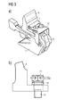
- Fig. 1 shows a view of the latch closure in the closed position.
- On a rail 1 is on one side of the rail foot Closure piece 2 by means of retaining clips 3, which hook under the rail at the other rail foot side attached.
- the adjusting tongue 4 of the switch is connected at its free end with a lock bearing 5.
- the adjusting tongue 4 is shown here in the adjacent position, ie the adjusting tongue 4 is pressed against the rail side.
- a closure pawl 6 is pivotally mounted in a bearing 7.
- a slide rod 8 is provided for the adjustment of the adjusting tongue 4, a slide rod 8 is provided. The slide rod 8 is moved transversely to the rail longitudinal axis by means of a drive, not shown.
- closure pawl 6 and the slide rod 8 are now designed such that the free end of the closure pawl 6 as in FIG. 1 shown under the foot of the rail 1 can slide through.
- This latch closure now causes the positioning tongue 4 to be positively connected via the locking pawl 6 to the rail 1 in the closed position.
- the setting of this connection can be achieved, for example, that the bearing 7 has an adjustment by means of eccentric.
- the orientation of the closure pawl 6 can be adjusted or readjusted such that a blocking surface 9 rests against the closure piece 2 with a defined clearance when the positioning tongue 4 bears against the flank of the rail 1.
- the lock stock 5 For mounting such a latch closure in a switch, inter alia, the lock stock 5 must be mounted at the foot of the adjusting tongue 4.
- the adjusting tongue 4 has a bore into which a locking screw 11 is screwed.
- the closure clip screw 11 is tightened according to the current state of the art with a maximum torque and then secured with a locking plate 12.
- the locking plate is designed as a spring plate and has a hole that corresponds to the screw head. It is first pushed over the hexagon head in the direction of the arrow and then snaps over the screw head when the screw head coincides with the hole in the locking plate 12.
- the hexagonal head of the locking clip screw 11 must be aligned with the locking plate 12, so that tightening the locking screw can be quite a re-tightening may be required by up to 60 °, which given the thread thickness of example M20 (and the associated thread pitches) again very much large forces required, which may possibly adversely affect the connected components.
- a first solution according to the invention for this task provides a closure bearing for a Weichenverstellan eleven with a foot of a Stellzunge penetrating locking bearing screw and a arranged between the foot and the screw head of the locking bearing screw spring assembly.
- the locking bearing screw with a relatively narrow definable Torque range are tightened and at the same time still has the rotational reserve to bring the position of the head of the locking bearing screw in accordance with a screw head depicting the hole in a locking plate, which then snaps when pushing over the head of the locking bearing screw as previously known.
- a second solution according to the invention for this purpose provides a closure bearing for a Weichenverstellan extract with a foot of a Stellzunge penetrating locking bearing screw and the head of the locking bearing screw annularly frictionally surrounding anti-rotation ring with an external toothing and adapted to this external toothing locking plate.
- the locking bearing screw it is also possible here to attract the locking bearing screw within a relatively small torque range and thereby align the locking bearing screw only in the Rast réellesmass the external teeth. If, for example, the outer toothing has a tooth number of 36 teeth, then the locking bearing screw must only be aligned within a range of a maximum of 10 °.
- the anti-rotation ring acts like an adapter for the Zahnungsmass and thus contributes to the fact that on the remaining construction of the lock bearing and the lock bearing screw no changes must be made, which is also absolutely beneficial for safety and approval considerations.
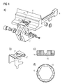
- FIG. 2 shows a schematic view of the adjusting tongue 4 with the lock bearing 7 fixed thereto in one opposite FIG. 1 enlarged view.
- the head 13 of the closure bearing screw 11 sets the closure bearing 7 with vertical pressure on the positioning tongue 4.
- the head 13 has a hexagon.
- the designed as a spring plate locking plate 12 has a hole that corresponds to the hexagon surface area. If the locking plate 12 is now pushed over the head 13, it bends upwards and locks in the moment above the head 13 when the hole and the head 13 are in complete agreement. Therefore, the head 13 must be aligned exactly with the hole in the locking plate 12.
- FIG. 3a now shows the situation according to FIG. 2 with a spring package 14 inserted according to the invention under the head 13 of the closure bearing screw 11 (detail view cf. FIG. 3b ).
- the lock bearing screw 11 can be set within a small torque range.
- this solution allows for a further slight tightening of the locking bearing screw 11 in order to bring the position of the screw head 13 into conformity with the hole in the locking plate 12.
- the spring reserve present in the spring assembly 14 ensures that the screw connection does not cause any unacceptable stresses in the screwed components.
- FIG. 4 shows the situation according to FIG. 2
- the anti-rotation adapter 15 has a ring-shaped design (compare Figure parts 4c and 4d) and has in its inner circumference a largely positive, but in each case non-positive course exactly to the course of the hexagonal head thirteenth the closure bearing screw 11 (see Figure 4d part).
- the anti-rotation adapter 15 On its outer circumference, the anti-rotation adapter 15 has an outer toothing 16, which is much finer than the hexagon of the head 13.
- a hole 17 in the locking plate 12 ' forms the course of the external teeth 16 exactly, so that the locking plate 12' engages over the anti-rotation adapter 15, if External teeth 16 and the hole 17 are in agreement.
- the locking bearing screw 11 or its head 13 need not be aligned during tightening. Smaller corrections of the screw position are possible by means of an insertable into the screw head 13 pin, which allow the fine adjustment of the locking bearing screw 11 relative to the contours of the hole 17 in the locking plate 12 '.
Landscapes
- Engineering & Computer Science (AREA)
- Mechanical Engineering (AREA)
- Seats For Vehicles (AREA)
- Connection Of Plates (AREA)
- Mechanical Control Devices (AREA)
Priority Applications (1)
| Application Number | Priority Date | Filing Date | Title |
|---|---|---|---|
| EP11179473.1A EP2479080A3 (fr) | 2011-01-19 | 2011-08-31 | Verrou à pince doté d'une vis de bride de fermeture |
Applications Claiming Priority (2)
| Application Number | Priority Date | Filing Date | Title |
|---|---|---|---|
| EP11151347 | 2011-01-19 | ||
| EP11179473.1A EP2479080A3 (fr) | 2011-01-19 | 2011-08-31 | Verrou à pince doté d'une vis de bride de fermeture |
Publications (2)
| Publication Number | Publication Date |
|---|---|
| EP2479080A2 true EP2479080A2 (fr) | 2012-07-25 |
| EP2479080A3 EP2479080A3 (fr) | 2015-10-28 |
Family
ID=44509072
Family Applications (1)
| Application Number | Title | Priority Date | Filing Date |
|---|---|---|---|
| EP11179473.1A Ceased EP2479080A3 (fr) | 2011-01-19 | 2011-08-31 | Verrou à pince doté d'une vis de bride de fermeture |
Country Status (3)
| Country | Link |
|---|---|
| US (1) | US8870127B2 (fr) |
| EP (1) | EP2479080A3 (fr) |
| CN (1) | CN102602428B (fr) |
Cited By (1)
| Publication number | Priority date | Publication date | Assignee | Title |
|---|---|---|---|---|
| EP2703249A1 (fr) * | 2012-09-03 | 2014-03-05 | Siemens Schweiz AG | Verrou à pince avec palier de fermeture réglable |
Families Citing this family (2)
| Publication number | Priority date | Publication date | Assignee | Title |
|---|---|---|---|---|
| NL2006119C2 (nl) * | 2011-02-02 | 2012-08-06 | Spot Safety Professionals On Track | Klemmechanisme voor het vastzetten van ten minste een voorwerp aan een rail alsmede een samenstel. |
| CN112458801A (zh) * | 2020-11-30 | 2021-03-09 | 张翔 | 尖轨位移补偿装置 |
Citations (1)
| Publication number | Priority date | Publication date | Assignee | Title |
|---|---|---|---|---|
| EP0624508A1 (fr) | 1993-05-10 | 1994-11-17 | Siemens Integra Verkehrstechnik Ag | Verrou à pince pour aiguillages de voies ferrées |
Family Cites Families (7)
| Publication number | Priority date | Publication date | Assignee | Title |
|---|---|---|---|---|
| DE1530373B1 (de) * | 1963-04-22 | 1970-05-14 | Peddinghaus Carl Dan Kg | Verschlusskastenbefestigung fuer den Klammerspitzen |
| CN87202869U (zh) * | 1987-03-10 | 1987-10-21 | 铁道部科学研究院铁道建筑研究所 | 轨条接头螺栓连接锁紧装置 |
| DE8707708U1 (de) * | 1987-05-29 | 1987-08-27 | Metacon AG, Zürich | Einrichtung zur Befestigung eines Eintauchausgusses |
| AT390084B (de) * | 1988-05-20 | 1990-03-12 | Voest Alpine Maschinenbau | Weiche mit einem herzstueck mit beweglicher haupt- und beispitze |
| US5501418A (en) * | 1994-10-03 | 1996-03-26 | Humphrey; John | Switch point roller assist apparatus |
| DE19502105C5 (de) * | 1995-01-24 | 2004-12-30 | Carl Dan. Peddinghaus Gmbh & Co Kg | Verschlußvorrichtung für Weichenzungen |
| US6732980B2 (en) * | 2002-10-08 | 2004-05-11 | Progress Rail Services Corp. | Railway frog wear component |
-
2011
- 2011-08-31 EP EP11179473.1A patent/EP2479080A3/fr not_active Ceased
-
2012
- 2012-01-18 US US13/352,396 patent/US8870127B2/en not_active Expired - Fee Related
- 2012-01-18 CN CN201210015124.8A patent/CN102602428B/zh active Active
Patent Citations (1)
| Publication number | Priority date | Publication date | Assignee | Title |
|---|---|---|---|---|
| EP0624508A1 (fr) | 1993-05-10 | 1994-11-17 | Siemens Integra Verkehrstechnik Ag | Verrou à pince pour aiguillages de voies ferrées |
Cited By (1)
| Publication number | Priority date | Publication date | Assignee | Title |
|---|---|---|---|---|
| EP2703249A1 (fr) * | 2012-09-03 | 2014-03-05 | Siemens Schweiz AG | Verrou à pince avec palier de fermeture réglable |
Also Published As
| Publication number | Publication date |
|---|---|
| US8870127B2 (en) | 2014-10-28 |
| EP2479080A3 (fr) | 2015-10-28 |
| CN102602428A (zh) | 2012-07-25 |
| CN102602428B (zh) | 2016-12-07 |
| US20120181393A1 (en) | 2012-07-19 |
Similar Documents
| Publication | Publication Date | Title |
|---|---|---|
| EP2318723B1 (fr) | Agencement de fixation avec compensation des tolerances | |
| EP3717786B1 (fr) | Dispositif de compensation de tolérance avec sécurité par serrage | |
| DE69006170T2 (de) | Schraubdübel, insbesondere für weiches Material, und dafür geeignetes Werkzeug. | |
| EP0400224A2 (fr) | Implant endo-osseux et outil | |
| WO2006042750A1 (fr) | Barre de traction-compression | |
| DE9409123U1 (de) | Vorrichtung zum Stabilisieren bzw. Komprimieren oder Distrahieren von Abschnitten der Wirbelsäule | |
| EP2032864B1 (fr) | Rondelle et assemblage à vis pourvu de ladite rondelle | |
| EP3586018B1 (fr) | Dispositif de fixation et module de fixation | |
| EP3032093B1 (fr) | Dispositif de fixation d'une pale de rotor sur un moyeu de rotor d'une éolienne | |
| DE3404118A1 (de) | Verfahren und vorrichtung zum anbringen einer mutter an einem plattenfoermigen werkstueck | |
| EP0905389A2 (fr) | Vis pour l'ancrage dans du béton | |
| EP2816243B1 (fr) | Élément de fixation | |
| EP2479080A2 (fr) | Verrou à pince doté d'une vis de bride de fermeture | |
| EP2479081B1 (fr) | Verrou à pince doté d'une vis de bride de fermeture | |
| DE102020205995B3 (de) | Toleranzausgleichsvorrichtung | |
| DE102009037820C5 (de) | Anordnung zur Verbindung von Holzbauteilen | |
| DE29805045U1 (de) | Kunststoffmutter | |
| EP3565776B1 (fr) | Installation de transport de récipients avec un élément de trajectoire échangeable | |
| EP3412246B1 (fr) | Support pour ébauche de pilier pour implants dentaires | |
| DE202008016230U1 (de) | Vorrichtung zum Verbinden von Bauteilen | |
| WO2018134109A1 (fr) | Système de fixation et rondelle | |
| DE3410868A1 (de) | Wiederverwendbare formschluessige muttersicherung | |
| DE102010032895A1 (de) | Verankerungssystem | |
| EP1028259B1 (fr) | Dispositif d'ancrage amovible d'un élément ignifuge à un élément métallique | |
| EP0020916B1 (fr) | Dispositif de fixation |
Legal Events
| Date | Code | Title | Description |
|---|---|---|---|
| PUAI | Public reference made under article 153(3) epc to a published international application that has entered the european phase |
Free format text: ORIGINAL CODE: 0009012 |
|
| AK | Designated contracting states |
Kind code of ref document: A2 Designated state(s): AL AT BE BG CH CY CZ DE DK EE ES FI FR GB GR HR HU IE IS IT LI LT LU LV MC MK MT NL NO PL PT RO RS SE SI SK SM TR |
|
| AX | Request for extension of the european patent |
Extension state: BA ME |
|
| PUAL | Search report despatched |
Free format text: ORIGINAL CODE: 0009013 |
|
| AK | Designated contracting states |
Kind code of ref document: A3 Designated state(s): AL AT BE BG CH CY CZ DE DK EE ES FI FR GB GR HR HU IE IS IT LI LT LU LV MC MK MT NL NO PL PT RO RS SE SI SK SM TR |
|
| AX | Request for extension of the european patent |
Extension state: BA ME |
|
| RIC1 | Information provided on ipc code assigned before grant |
Ipc: B61L 5/10 20060101AFI20150918BHEP |
|
| 17P | Request for examination filed |
Effective date: 20160304 |
|
| RBV | Designated contracting states (corrected) |
Designated state(s): AL AT BE BG CH CY CZ DE DK EE ES FI FR GB GR HR HU IE IS IT LI LT LU LV MC MK MT NL NO PL PT RO RS SE SI SK SM TR |
|
| STAA | Information on the status of an ep patent application or granted ep patent |
Free format text: STATUS: EXAMINATION IS IN PROGRESS |
|
| 17Q | First examination report despatched |
Effective date: 20170322 |
|
| STAA | Information on the status of an ep patent application or granted ep patent |
Free format text: STATUS: THE APPLICATION HAS BEEN REFUSED |
|
| 18R | Application refused |
Effective date: 20180129 |