EP2329738A2 - Fermeture éclair étanche à l'eau - Google Patents
Fermeture éclair étanche à l'eau Download PDFInfo
- Publication number
- EP2329738A2 EP2329738A2 EP10252038A EP10252038A EP2329738A2 EP 2329738 A2 EP2329738 A2 EP 2329738A2 EP 10252038 A EP10252038 A EP 10252038A EP 10252038 A EP10252038 A EP 10252038A EP 2329738 A2 EP2329738 A2 EP 2329738A2
- Authority
- EP
- European Patent Office
- Prior art keywords
- slider
- cap
- leading edge
- slider cap
- body portion
- Prior art date
- Legal status (The legal status is an assumption and is not a legal conclusion. Google has not performed a legal analysis and makes no representation as to the accuracy of the status listed.)
- Withdrawn
Links
Images








Classifications
-
- A—HUMAN NECESSITIES
- A44—HABERDASHERY; JEWELLERY
- A44B—BUTTONS, PINS, BUCKLES, SLIDE FASTENERS, OR THE LIKE
- A44B19/00—Slide fasteners
- A44B19/24—Details
- A44B19/32—Means for making slide fasteners gas or watertight
-
- A—HUMAN NECESSITIES
- A44—HABERDASHERY; JEWELLERY
- A44B—BUTTONS, PINS, BUCKLES, SLIDE FASTENERS, OR THE LIKE
- A44B19/00—Slide fasteners
- A44B19/24—Details
- A44B19/26—Sliders
-
- Y—GENERAL TAGGING OF NEW TECHNOLOGICAL DEVELOPMENTS; GENERAL TAGGING OF CROSS-SECTIONAL TECHNOLOGIES SPANNING OVER SEVERAL SECTIONS OF THE IPC; TECHNICAL SUBJECTS COVERED BY FORMER USPC CROSS-REFERENCE ART COLLECTIONS [XRACs] AND DIGESTS
- Y10—TECHNICAL SUBJECTS COVERED BY FORMER USPC
- Y10T—TECHNICAL SUBJECTS COVERED BY FORMER US CLASSIFICATION
- Y10T24/00—Buckles, buttons, clasps, etc.
- Y10T24/25—Zipper or required component thereof
- Y10T24/2509—Plural independently movable sliders
-
- Y—GENERAL TAGGING OF NEW TECHNOLOGICAL DEVELOPMENTS; GENERAL TAGGING OF CROSS-SECTIONAL TECHNOLOGIES SPANNING OVER SEVERAL SECTIONS OF THE IPC; TECHNICAL SUBJECTS COVERED BY FORMER USPC CROSS-REFERENCE ART COLLECTIONS [XRACs] AND DIGESTS
- Y10—TECHNICAL SUBJECTS COVERED BY FORMER USPC
- Y10T—TECHNICAL SUBJECTS COVERED BY FORMER US CLASSIFICATION
- Y10T24/00—Buckles, buttons, clasps, etc.
- Y10T24/25—Zipper or required component thereof
- Y10T24/2511—Zipper or required component thereof with distinct, stationary means for anchoring slider
-
- Y—GENERAL TAGGING OF NEW TECHNOLOGICAL DEVELOPMENTS; GENERAL TAGGING OF CROSS-SECTIONAL TECHNOLOGIES SPANNING OVER SEVERAL SECTIONS OF THE IPC; TECHNICAL SUBJECTS COVERED BY FORMER USPC CROSS-REFERENCE ART COLLECTIONS [XRACs] AND DIGESTS
- Y10—TECHNICAL SUBJECTS COVERED BY FORMER USPC
- Y10T—TECHNICAL SUBJECTS COVERED BY FORMER US CLASSIFICATION
- Y10T24/00—Buckles, buttons, clasps, etc.
- Y10T24/25—Zipper or required component thereof
- Y10T24/2514—Zipper or required component thereof with distinct member for sealing surfaces
-
- Y—GENERAL TAGGING OF NEW TECHNOLOGICAL DEVELOPMENTS; GENERAL TAGGING OF CROSS-SECTIONAL TECHNOLOGIES SPANNING OVER SEVERAL SECTIONS OF THE IPC; TECHNICAL SUBJECTS COVERED BY FORMER USPC CROSS-REFERENCE ART COLLECTIONS [XRACs] AND DIGESTS
- Y10—TECHNICAL SUBJECTS COVERED BY FORMER USPC
- Y10T—TECHNICAL SUBJECTS COVERED BY FORMER US CLASSIFICATION
- Y10T24/00—Buckles, buttons, clasps, etc.
- Y10T24/25—Zipper or required component thereof
- Y10T24/2598—Zipper or required component thereof including means for obstructing movement of slider
Definitions
- the invention relates generally to slider caps that snap onto a slider of a zipper to thereby provide improved water repellent zippers and zipper structures.
- Objects that include zippers may be exposed to wet conditions such that water penetrates into open spaces or crevices of the zipper.
- wet conditions such that water penetrates into open spaces or crevices of the zipper.
- water may penetrate the zipper and seep into the surface underneath the zipper.
- the contents of the luggage and/or bags may become wet and damaged, and a person wearing the outerwear might become uncomfortable and cold.
- Water repellent zippers are known that decrease the amount of water that penetrates between the teeth and/or zipper tape of a zipper.
- Such zippers may include polyurethane lamination on the zipper tape or specially-shaped teeth, both of which provide a barrier to decrease water penetration into the zipper.
- water may also penetrate into the gap that appears between the zipper slider and an end piece of the zipper.
- coil zippers typically have a metal crimp at the end piece. When the slider is pulled up to fully engage the zipper, then the leading edge of the slider contacts the end piece; however, an open space or gap may be created between the slider and the end piece.
- FIGS. 4 and 5 in some applications there are two sliders that meet in a head-to-head configuration on the same zipper. In such configurations the two sliders contact one another and an open space may be created on either side of the point of contact between the two sliders. Water and other elements may penetrate the open spaces created by the sliders.
- a water repellent zipper assembly comprising water repellent zipper tape, a slider comprising a leading edge and a pull tab, and a slider cap.
- the slider cap may includes a body portion which has an outer surface and an inner surface opposite the outer surface, a first sidewall protruding from one end portion of the body portion in a width direction of the body portion, a second sidewall opposite the first sidewall and protruding from another end portion of the body portion in the width direction of the body portion, and a snap tab extending between at least a portion of an inner surface of the first and second sidewalls.
- the inner surface of the body portion and the snap tab may define a pocket that receives the pull tab of the slider.
- the body portion of the slider cap may cover the slider, and the leading edge of the slider cap may extend beyond the leading edge of the slider, to reduce the amount of water introduced around the perimeter of the slider.
- a garage that is attached to the zipper tape.
- the garage may comprise an outer surface, an inner surface opposite the outer surface, at least three sidewalls, and an aperture.
- the slider and the slider cap may be inserted into the aperture of the garage such that the inner surface of the garage contacts the outer surface of the slider cap. The contact between the garage and the slider cap improves engagement between the two parts, which may reduce the amount of water introduced around the perimeter of the slider and into the garage.
- a male slider cap as described above may receive and cover the first slider to thereby reduce the amount of water introduced around the perimeter of the first slider.
- a female slider cap to cover and repel water from the second slider.
- the female slider cap may includes a body portion which has an outer surface, an inner surface opposite the outer surface, and a leading edge, a first sidewalls protruding from one end portion of the body portion in a width direction of the body portion, a second sidewall opposite the first sidewall and protruding from another end portion of the body portion in the width direction of the body portion, and a snap tab extending between at least a portion of an inner surface of the first and second sidewalls.
- the inner surface of the body portion of the female slider cap and the snap tab may define a pocket that receives the pull tab of the second slider.
- the outer surface of the body portion of the female slider cap may cover the second slider, and the leading edge of the female slider cap may extend beyond the leading edge of the second slider, to reduce the amount of water introduced around the perimeter of the second slider.
- the leading edge of the male slider cap may be inserted into an aperture formed in the leading edge of the female slider cap to reduce the amount of water introduced around the respective leading edges of the first and second sliders.
- the water repellent zipper assembly it is possible to improve the engagement between the slider and the garage to improve the water-repellent property of the slider and further to improve the water-repellent property of the sliders arranged in a head-to-head configuration.
- FIG. 1A is a perspective view of a male slider cap and a slider according to certain embodiments of the invention.
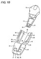
- Fig. 1B is a perspective view of the male slider cap shown in FIG. 1A , separated from the slider shown in FIG. 1A .
- FIG. 1C is a perspective view of the male slider cap shown in FIG. 1B , is attached to the slider shown in FIG. 1B .
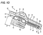
- FIG. 1D is a cross-sectional perspective view of the male slider cap and slider as shown in FIGS. 1A-1C .
- FIG. 2A is a top plan view of the male slider cap as shown in FIGS. 1A-1D .
- FIG. 2B is a side view of the male slider cap as shown in FIG. 2A .
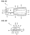
- FIG. 2C is a bottom view of the male slider cap as shown in FIG. 2A .
- FIG. 2D is a front view of the male slider cap as shown in FIG. 2A .
- FIG. 3A is a perspective view of a garage, and a male slider cap docking in the garage, according to certain embodiments of the invention.
- FIG. 3B is a perspective view of the male slider cap docked in the garage.
- FIG. 3C is a cross-sectional view of a male slider cap docked in the garage shown in FIG. 3B .
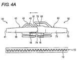
- FIG. 4A is a side view of a male slider cap docked with a female slider cap according to certain embodiments of the invention.
- FIG. 4B is a cross-sectional perspective view of the mating male and female slider caps as shown in FIG. 4A .
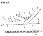
- FIG. 5A is a schematic side view illustrating the pivot angle created by a slider cap without certain features as described herein, and FIG. 5B shows the pivot angle created by female slider caps according to certain embodiments.
- FIG. 6A is a top plan view of a female slider cap according to a certain embodiment of the invention.
- FIG. 6B is a side view of the female slider cap shown in FIG. 6A .
- FIG. 6C is a bottom view of the female slider cap shown in FIG. 6A .
- FIG. 6D is a front view of the female slider cap shown in FIG. 6A .
- a water repellent zipper assembly which includes a water repellent zipper tape 12, a slider 16 including a pull tab 17 and a slider cap 30.
- the slider cap 30 includes a body portion 43 having an outer surface 42 and an inner surface 44 opposite the outer surface 42, a first sidewall 38 protruding from one end portion of the body portion 43 in a width direction of the body portion 43, a second sidewall 38 opposite the first sidewall 38 and protruding from another end portion of the body portion 43 in the width direction of the body portion 43, and a snap tab 34, 35 extending between at least a portion of an inner surface of the first and second sidewalls 38.
- the inner surface 44 of the body portion 43 and the snap tab 34, 35 define a pocket 45 that receives the pull tab 17 of the slider 16.
- the body portion 43 of the slider cap 30 covers the slider 16 and a leading edge 40 of the slider cap 30 extends beyond a leading edge of the slider 30.
- the pull tab 17 is inserted into the male slider cap 30 starting on the leading edge 40 of the male slider cap 30 and proceeding towards the trailing edge 41.
- the male slider cap 30 includes a body portion 43 which has an outer surface 42 and an inner surface 44 and the pull tab 17 is received in a pocket 45 that is defined between a snap tab 34, 35 of the male slider cap 30 and the inner surface 44 of the body portion 43.
- the snap tab 34, 35 extends from the inner surfaces of the sidewalls 38 formed at both sides of the body portion 43 of the male slider cap 30. As shown in FIG. 1C the snap tab 34, 35 spans substantially the entire width of the male slider cap 30. Thus, a pocket 45 is created between the snap tab 34, 35 and the inner surface 44 of the male slider cap 30. This pocket 45 receives the pull tab 17 of the slider 16.
- the leading edge 40 of the male slider cap 30 and the leading edge of the slider 16 are positioned at a side to which the slider 30 slides so as to close the zipper tape 12.
- a trailing edge of the male slider cap 30 and a trailing edge of the slider 30 are positioned at a side to which the slider slides so as to open the zipper tape 12.
- the male slider cap 30 has the pocket 45 at the trailing edge thereof
- the snap tab is composed of two separate portions—a first portion 34 and a second portion 35—that are separated from each other by a small gap. In other embodiments, however, the snap tab comprises a single element and does not have a separating gap.
- this disclosure will refer to the snap tabs 34, 35 as comprising two portions, although it should be understood that the disclosure is in no way limiting and the snap tab may comprise a single element.
- the snap tab 34 includes a ramp 36.
- the first portion of the snap tab 34 includes an engagement portion including the ramp 36 which is adjacent to a through hole and slightly inclined toward the inner surface of the snap tab 34.
- the ramp 36 is formed such that a gap between the inner surface 44 of the body portion 43 and an inner surface of the snap tab 34 becomes narrower from an inlet side of the pocket 45 toward the trailing edge 41 side of the male slider cap 30.
- the pull tab 17 includes an aperture 19.
- the ramp 36 is configured to snap into the aperture 19 of the pull tab 17 to receive the pull tab 17, that is the ramp 36 is dimensioned such that it fits into an engaged portion, i.e. the aperture 19 formed in some pull tabs 17.
- the aperture 19 is illustrated in FIG. 1B , which also shows a bump 20 that may be provided adjacent to the aperture 19 and beyond the aperture 19 toward the leading edge side, on the front and back sides of the pull tab 17.
- FIG. 1C shows how the ramp 36 fits into the aperture 19. As the pull tab 17 is inserted into the pocket 45 of the male slider cap 30, the leading edge of the pull tab 17 begins to travel up the ramp 36. When fully inserted the ramp 36 snaps into the aperture 19 of the pull tab 17.
- the snap tab 34, 35 is divided at its center position in the width direction thereof, from the inlet side of the pocket 45 toward the opening portion 47.
- the small gap between the portions of the snap tab 34, 35 allows the portions to flex independently of one another such that the ramp 36 can snap into the aperture 19 on the pull tab 17.
- the bump 20 is fixed on a step portion formed at the leading edge side of the ramp 36, i.e. on a peripheral wall 36 which defines the opening portion 47, and the bump 20 further prevents the pull tab 17 from pulling out of the pocket 45.
- the pull tab 17 is thus snapped within the male slider cap 30 by the fit between the ramp 36 and the aperture 19 and bump 20 of the pull tab 17.
- the body portion 43 of the male slider cap 30 is formed so as to be larger in size than an entire length and an entire width of the slider 16 including the pull tab 17 and the outer surface 42 of the male slider cap 30 covers the slider 16 to thereby cover any open spaces that may be around the perimeter of the slider 16.
- the leading edge 40 of the male slider cap 30 is formed with an over-hanging portion which protrudes from the slider 16 by a distance (d1). This distance (d1 of the male slider cap 30 is set so as to be larger than any open spaces that may be created between the slider 16 and the end piece 18 of the zipper to cover the open spaces.
- the size of the male slider cap 30 increases, so does the size of the perimeter around the slider 16 that is covered by the male slider cap 30, as shown in FIG. 1A .
- more or less water repellent properties may be achieved by modifying the size of the male slider cap 30.as desired.
- the water repellent properties are also improved by the two sidewalls 38 which protrudes from both side ends of the body portion 43 of the male slider cap 30 and the trailing wall 41 which protrudes from the trailing end side of the body portion 43 of the male slider cap 30.
- the height (h) from the inner surface 44 of the body portion 43 to tip ends of each wall 38, 41 when the slider 16 is accommodated in the male slider cap 30 extends down beyond a back surface of the pull tab 17 and preferably extends down beyond an upper surface of upper blade 16a of the slider 16 to cover any open spaces that might be formed around the perimeter of the slider 16.
- the walls 38, 41 also provide other functions for the male slider cap 30.
- the walls 38, 41 may provide for a secure fit with the pull tab 17 and the slider 16.
- the sidewalls 38 may include a concave portion 39 that serves as a finger grip that a user may grasp when engaging the slider cap 30.
- the male slider cap 30 is formed with two sidewalls 38 and the trailing wall 41. No wall at the leading edge side, i.e. no front wall is formed and the leading edge side of the male slider cap 30 is opened. With this configuration, it is possible to insert the slider 16 into the male slider cap by sliding the male slider cap 30 with respect to the slider 16, and to easily accommodates the pull tab 17 in the pocket 45.
- male slider caps 30 may include a domed outer surface 42 to accommodate the pull tab attachment portion 15 of the slider 16.
- pull tab attachment portion clearance portion 32 may be provided on the inner surface 44 of the male slider cap 30.
- the pull tab attachment portion clearance portion 32 provides clearance between the pull tab attachment portion 15 of the slider 16 and the inner surface 44 of the male slider cap 30.
- the pull tab attachment portion clearance portion 32 may be dimensioned so as to serve as a guide to facilitate the insertion of the pull tab 17, as shown in FIG. 1B .
- the male slider cap 30 also include a puller attachment portion 46 on the outer surface 42 thereof.
- the puller attachment portion 46 serves as an anchor for a puller 48 such as a cord puller.
- the puller attachment portion 46 may be any dimension or shape that is sufficient to receive the puller 48.
- the puller attachment portion 46 of the male slider cap 30 is formed at a center position of the outer surface 42 of the body portion 43 of the male slider cap 30 and positioned generally above the pull tab attachment portion 15 and main body of the slider 16, as shown in FIG. 1D .
- a female slider cap 62 may include a puller attachment portion 80 with different placement (and shapes).
- the puller 48 to be attached may be composed of fabric, woven strands, a metal chain, or a leather cord, but not limited thereto.
- the puller 48 may be composed of a variety of materials or the puller 48 may be a handle which is configured similarly to the pull tab 17.
- Slider caps according to embodiments of the invention may be composed of a variety of materials, including but not limited to hard plastic such as acetal or various metals. Harder materials for the slider caps 30, 62 help to maintain the secure fit and snapping action on the pull tab 17. Depending on the application, it may be desirable to make the slider caps 30, 62 with a material that is ultra-violet resistant or that has a particular color fastness.
- the slider caps 30, 62 may be manufactured by a variety of processes, including but not limited to injection molding.
- Certain embodiments may also include a garage 50 in which to dock the male slider cap 30. Such embodiments are illustrated in FIGS. 3A-3C . It should be understood that in actual operation the slider 16 and garage 50 in each of FIGS. 3A-3C would be attached to zipper tape 12; however, the zipper tape 12 is not shown in FIG. 3A in order to better illustrate the particular features of the slider 16, male slider cap 30, and garage 50. The zipper tape 12 is shown in FIGS. 3B and 3C .
- the garage 50 has at least an outer surface, an inner surface opposite the outer surface, at least three sidewalls and an aperture. According to the certain embodiments, the garage 50 includes one mounting edge 52, an outer surface 54, inner surface 55, sidewalls 56, and an aperture 57 in which to dock the male slider cap 30. As shown in FIG. 3B , the garage 50 may be attached to the zipper tape 12 along its mounting edge 52 by any method known to those of skill in the art, including but not limited to sewing, RF welding, gluing, stapling, or taping. The garage 50 may be attached anywhere along the length of a zipper tape 12, including but not limited to the end piece 18 of the zipper 10. If the garage 50 is attached adjacent to the end piece 18, the garage 50 may cover any open spaces that are formed near the end piece 18.
- the garage 50 may be composed of a variety of materials.
- the first material may be harder than the second material. That is, the garage 50 may be composed of a material that is softer and more pliable than the material of the male slider cap 30.
- Pliable materials for the garage 50 might be desired in embodiments wherein the garage 50 will be subjected to forceful impacts. Such pliable materials may simply bend and deform under impact, whereas harder materials might become damaged.
- the garage 50 may be composed of rubber, silicone, fabric, or laminated fabric.
- the leading edge 40 of the male slider cap 30 is inserted into the aperture 57 of the garage 50.
- the inner surface 55 of the garage 50 contacts the outer surface 42 of the male slider cap 30. This contact improves engagement between the garage 50 and the male slider cap 30.
- the garage 50 may be made of a material with a high coefficient of friction (such as rubber or silicone).
- the inner surface 55 of the garage 50 may "stick to" or otherwise have a friction fit with the outer surface 42 of the male slider cap 30, which may further improve engagement between the garage 50 and the male slider cap 30.
- Such improved engagement may reduce any gaps around the aperture 57 of the garage 50, which may lead to improved water repellent properties.
- Certain embodiments of the present invention provide male slider caps 30 that contact the garage 50, which improves engagement and may additionally lead to improved water repellent properties.
- the water repellent properties may be improved even further by increasing the distance in which the male slider cap 30 is inserted into the garage 50.
- Increasing the insertion distance also provides for a more secure fit between the male slider cap 30 and the garage 50.
- the increased insertion distance may be accomplished in several ways.
- the notch 58 receives the puller attachment portion 46 of the male slider cap 30 when the leading edge 40 of the male slider cap 30 is inserted into the aperture 57 of the garage 50.
- the notch 58 is dimensioned to receive the puller attachment portion 46 of the male slider cap 30, and allows the male slider cap 30 to be docked more fully in the garage 50.
- the notch 58 may optionally include a hood 60 to cover any open spaces that are formed along the perimeter of the notch 58.
- an increased distance (d2) between the leading edge 40 of the male slider cap 30 and where the puller attachment portion 46 attaches to the male slider cap 30 may be provided.
- the distance (d2) increases so does the surface area that is in contact between the garage 50 and the male slider cap 30, thus improving water repellent properties and securing the fit between the male slider cap 30 and the garage 50.
- the distance (d2) extends beyond at least the leading edge of the slider 16 and the distance (d2) is within a range in which a portion of the slider 16 can be accommodated in the garage 50.
- certain embodiments of the invention include a female slider cap 62 that mates with the male slider cap 30 that may be used fox two sliders 16 that meet in a head-to-head configuration on zipper tape 12.
- the zipper tape 12 that is shown in FIGS. 4A to 5B is shown slightly below and not attached to the sliders 16 for illustration purposes only in order to more clearly show the design of the sliders 16 and the slider caps 30, 62. It should be understood that in actual application, the sliders 16 are attached to the zipper tape 12.
- the water repellent properties of the female slider cap 62 are similar to those described above with respect to the male slider cap 30.
- the female slider cap 62 covers the slider 16, a leading edge 74 of the female slider cap 62 extends beyond a leading edge of the slider 16 and prevents water from entering any open spaces that might be formed around the perimeter of the slider 16.
- the size of the female slider cap 62 increases, so does the size of the perimeter around the slider 16 that is covered and protected by the female slider cap 62. But as one of skill in the art will understand, if the size of the female slider cap 62 is too large, then the water repellent properties may tend to suffer.
- the female slider cap 62 provides increased water repellent properties for two sliders 16 that meet in a head-to-head configuration.
- an open space may be formed around the point of contact between the two sliders 16.
- the leading edge 74 of the female slider cap 62 is formed with an aperture into which the leading edge 40 of the male slider cap 30 is to be inserted.
- the female slider cap 62 may include a domed outer surface 76 that is dimensioned to receive the leading edge 40 of the male slider cap 30, and to create an "awning" around the points of contact between the two sliders 16, thus covering any open spaces that might be formed where the two sliders 16 meet.
- this "awning" design of the female slider cap 62 provides increased water repellent properties for two sliders 16 that meet in a head-to-head configuration.
- the awning design is also an improvement from known designs that required a third element (other than the male slider cap 30 or female slider cap 62) to provide water repellent properties.
- the female slider cap 62 itself (and docking with the male slider cap 30) provides the water repellent properties.
- a puller attachment portion 80 to which a puller 82 such as a cord puller is attached is provided on the outer surface 76 of the body portion 63 of the female slider cap 62.
- the puller attachment portion 80 of the female slider cap 62 (the “female puller attachment portion") may be shaped and positioned differently than the puller attachment portion 46 of the male slider cap 30 (the “male pullet attachment portion”).
- the female puller attachment portion 80 may be shaped like a diamond lying on its side such that the leading edge 81 of the female puller attachment portion 80 is formed to protrude over the leading edge 74 of the female slider cap 62. As illustrated in FIGS.
- the leading edge 81 of the female puller attachment portion 80 may extend from the center thereof in the width direction thereof at angles ⁇ between 10-20 degrees as measured from the outer surface 76 of the female slider cap 62.
- the leading edge 74 of the female slider cap 62 may be pointed so that the leading edge 74 extends beyond the rest of the female slider cap 62. In certain embodiments the leading edge 74 may be pointed at angles ⁇ between 5-10 degrees. It should be understood that the leading edge 74 may be domed, curved, or any other extending shape and the invention is not limited to only "pointed" leading edges. The leading edge 74 allows the female puller attachment portion 80 to extend even further out from the female slider cap 62.
- FIG. 5A illustrates a pivot angle B that is formed when a zipper having a female slider cap 62 without an extended female puller attachment portion 80 is engaged. Without an extended female puller attachment portion 80, the pivot angle B is increased such that the sidewalls 70 of the female slider cap 62 drag on the zipper tape 12, making it difficult to engage the zipper. Additionally, the increased pivot angle B causes the outer surface 76 of the female slider cap 62 to be misaligned underneath the male slider cap 30. Thus the user must re-position the female slider cap 62 in the proper position over the male slider cap 30 (the proper position is shown in FIG. 4A ).
- embodiments having an extended female puller attachment portion 80 reduce the pivot angle B, thus making it easier to engage the zipper.
- the extended female puller attachment portion 80 and the pointed leading edge 74 are not improperly pushed underneath the male slider cap 30. Rather, the extended female puller attachment portion 80 and the pointed leading edge 74 actually push the leading edge 40 of the male slider cap 30 down. Pushing down the male slider cap 30 facilitates proper alignment, because as illustrated in FIG. 4A the male slider cap 30 is designed to be received in the female slider cap 62.
- the female slider cap 62 includes many of the same features as the male slider cap 30.
- the female slider cap 62 also includes a body portion 63, a snap tab 66, 67, a ramp 68, peripheral wall 68a, an opening portion 65, sidewalls 70, an optional concave portion 72, trailing wall 73, outer surface 76, inner surface 78, and pull tab attachment portion clearance portion 64 as described above with respect to the male slider cap 30.
- the female slider cap 62 may be composed of the same materials and made by the same manufacturing process as described above with respect to the male slider cap 30.
- any type of slider 16 may be used in embodiments of the invention, including either locking or non-locking sliders 16.
- the zipper 10 may be any type of zipper, including but not limited to water repellent zippers or non-water repellent zippers.
- the zippers may be of any size, including but not limited to traditional No. 5 or No. 8 zippers. Changing the type and size of the slider 16 and/or zipper 10 may result in changes to the dimensions of the slider caps 30, 62 or garage 50 or other zipper components described herein.
Landscapes
- Slide Fasteners (AREA)
Applications Claiming Priority (1)
| Application Number | Priority Date | Filing Date | Title |
|---|---|---|---|
| US12/628,813 US8375528B2 (en) | 2009-12-01 | 2009-12-01 | Water repellent slider cap for zippers |
Publications (2)
| Publication Number | Publication Date |
|---|---|
| EP2329738A2 true EP2329738A2 (fr) | 2011-06-08 |
| EP2329738A3 EP2329738A3 (fr) | 2012-05-23 |
Family
ID=43585604
Family Applications (1)
| Application Number | Title | Priority Date | Filing Date |
|---|---|---|---|
| EP10252038A Withdrawn EP2329738A3 (fr) | 2009-12-01 | 2010-12-01 | Fermeture éclair étanche à l'eau |
Country Status (6)
| Country | Link |
|---|---|
| US (2) | US8375528B2 (fr) |
| EP (1) | EP2329738A3 (fr) |
| JP (1) | JP2011115572A (fr) |
| KR (1) | KR101240755B1 (fr) |
| CN (1) | CN102078053B (fr) |
| TW (1) | TW201129332A (fr) |
Families Citing this family (19)
| Publication number | Priority date | Publication date | Assignee | Title |
|---|---|---|---|---|
| EP2717747B1 (fr) * | 2011-06-13 | 2018-09-12 | CleanBrands, LLC | Barrière protectrice pour un ensemble fermeture à glissière |
| CN102813343B (zh) * | 2012-08-14 | 2016-08-03 | 苏州指南针服饰有限公司 | 拉链盖帽的生产模具和生产方法 |
| US20140082895A1 (en) * | 2012-09-27 | 2014-03-27 | Jennifer E. Gold | Zipper cover and method |
| WO2014188581A1 (fr) * | 2013-05-24 | 2014-11-27 | Ykk株式会社 | Élément de fixation coulissant |
| CN103315459A (zh) * | 2013-07-01 | 2013-09-25 | 垦青(浙江)拉链有限公司 | 一种防水拉链 |
| KR101427539B1 (ko) | 2013-12-05 | 2014-08-07 | 윤해광 | 보조지퍼가 형성된 지퍼 |
| US11109650B2 (en) | 2014-12-04 | 2021-09-07 | Nite Ize, Inc. | Systems and methods for improved zipper slider garage |
| EP3226712B1 (fr) * | 2014-12-04 | 2020-02-05 | Nite Ize, Inc. | Systèmes d'amélioration de partie d'extrémité de curseur de fermeture à glissière |
| JP3198713U (ja) * | 2015-05-07 | 2015-07-16 | Ykk株式会社 | スライダー用装着具を備えたスライダー |
| GB2541891B (en) * | 2015-09-01 | 2018-07-11 | Versapak Int Ltd | Sealing device |
| TWI558335B (zh) * | 2016-01-08 | 2016-11-21 | Waterproof seal open tail zipper | |
| US10687589B2 (en) | 2016-04-14 | 2020-06-23 | Cleanbrands, Llc | Protective enclosure for a zipper |
| CN107232698B (zh) * | 2017-06-20 | 2021-01-15 | 刘科军 | 防水拉扣 |
| JP7001812B2 (ja) * | 2018-03-19 | 2022-02-10 | Ykk株式会社 | スライドファスナー |
| JP6782899B2 (ja) * | 2018-10-30 | 2020-11-11 | 星野太郎バッグデザイン研究株式会社 | リュックサック |
| US11363860B2 (en) | 2019-11-23 | 2022-06-21 | Talon Technologies, Inc. | Waterproof curved zippers |
| JP2023503233A (ja) | 2019-11-23 | 2023-01-27 | タロン テクノロジーズ、インコーポレイティッド | 湾曲ジッパー |
| US11363858B2 (en) * | 2020-04-06 | 2022-06-21 | Airo Importation, Inc. | Waterproof zipper pull system |
| CN113631060B (zh) * | 2021-02-09 | 2024-04-19 | 浙江华圣达拉链科技有限公司 | 一种拉链的拉头结构和拉链 |
Family Cites Families (17)
| Publication number | Priority date | Publication date | Assignee | Title |
|---|---|---|---|---|
| GB440781A (en) | 1935-05-21 | 1936-01-06 | Harry Krantz | Improvements relating to sliding clasp fasteners |
| US2928156A (en) * | 1957-06-19 | 1960-03-15 | New Zipper Corp | Slide fastener |
| GB879771A (en) * | 1958-01-08 | 1961-10-11 | Gandolph Doelter | Improvements in sliding clasp fasteners |
| GB2069317B (en) * | 1980-01-31 | 1983-04-07 | Yoshida Kogyo Kk | Ornamental attachments for slide fastener sliders |
| US4873750A (en) * | 1988-01-13 | 1989-10-17 | Tracy Richard J | Attachment for slide fastener slider pull tab |
| JP3393568B2 (ja) * | 1995-08-31 | 2003-04-07 | ワイケイケイ株式会社 | 自動停止装置付スライドファスナー用スライダー |
| JP3393572B2 (ja) * | 1996-04-30 | 2003-04-07 | ワイケイケイ株式会社 | 自動停止装置付スライドファスナー用スライダーおよびそのスライダーのカバー成形金型 |
| US6026547A (en) * | 1997-05-15 | 2000-02-22 | O'donnell Kiely; Alice Mary | Immobilized alignment closure system |
| US6701584B2 (en) | 2002-03-21 | 2004-03-09 | The Coleman Company, Inc. | Zipper guard |
| ITTO20020688A1 (it) * | 2002-07-31 | 2004-02-01 | Ykk Italia Spa | Dispositivo di trazione con elemento di copertura, |
| TWI220382B (en) * | 2003-08-21 | 2004-08-21 | Universal Trim Supply Co Ltd | Method for producing decorative cover of waterproof slider |
| DE202004006114U1 (de) | 2004-04-15 | 2004-08-12 | Ortlieb, Hartmut | Wasserdichter Reißverschluss mit zwei Schiebern |
| JP2006061378A (ja) | 2004-08-26 | 2006-03-09 | Ykk Corp | スライドファスナー |
| US7114223B2 (en) | 2004-11-15 | 2006-10-03 | Nike, Inc. | Covered zipper pull assembly |
| JP4628233B2 (ja) * | 2005-09-29 | 2011-02-09 | Ykk株式会社 | スライドファスナーの防水用上止 |
| JP4906303B2 (ja) * | 2005-10-04 | 2012-03-28 | Ykk株式会社 | 防水性スライドファスナー |
| KR200422256Y1 (ko) | 2006-01-06 | 2006-07-25 | 충 츠완 엔터플라이즈 컴퍼니 리미티드 | 지퍼 슬라이드의 조립 구조 |
-
2009
- 2009-12-01 US US12/628,813 patent/US8375528B2/en active Active
-
2010
- 2010-11-02 JP JP2010246304A patent/JP2011115572A/ja active Pending
- 2010-12-01 KR KR1020100121262A patent/KR101240755B1/ko not_active Expired - Fee Related
- 2010-12-01 EP EP10252038A patent/EP2329738A3/fr not_active Withdrawn
- 2010-12-01 CN CN201010571852.8A patent/CN102078053B/zh active Active
- 2010-12-01 TW TW099141783A patent/TW201129332A/zh unknown
-
2012
- 2012-09-10 US US13/608,127 patent/US8464404B2/en active Active
Also Published As
| Publication number | Publication date |
|---|---|
| KR101240755B1 (ko) | 2013-03-07 |
| CN102078053A (zh) | 2011-06-01 |
| TW201129332A (en) | 2011-09-01 |
| CN102078053B (zh) | 2012-11-28 |
| JP2011115572A (ja) | 2011-06-16 |
| US20120324680A1 (en) | 2012-12-27 |
| US8464404B2 (en) | 2013-06-18 |
| EP2329738A3 (fr) | 2012-05-23 |
| US20110126383A1 (en) | 2011-06-02 |
| HK1155332A1 (en) | 2012-05-18 |
| KR20110061502A (ko) | 2011-06-09 |
| US8375528B2 (en) | 2013-02-19 |
Similar Documents
| Publication | Publication Date | Title |
|---|---|---|
| EP2329738A2 (fr) | Fermeture éclair étanche à l'eau | |
| KR100367253B1 (ko) | 슬라이드 파스너용 슬라이더의 지퍼 견인 장치 | |
| CN109788827A (zh) | 防水性拉链 | |
| US9138033B2 (en) | Top stop for slider | |
| US9220323B2 (en) | Slider provided with handle at rear for slide fastener | |
| JP5143285B2 (ja) | スライドファスナー | |
| EP2100532B1 (fr) | Fermeture à glissière et butée supérieure pour fermeture à glissière | |
| EP0821892A1 (fr) | Curseur à verrouillage automatique | |
| CN108024608A (zh) | 带有止动机构的行李件 | |
| JP5274662B2 (ja) | スライドファスナー | |
| TWI433654B (zh) | Zipper with the slider | |
| EP1236413A3 (fr) | Butée d'arrêt supérieure pour fermeture à glissière | |
| JP2002136309A (ja) | スライドファスナー用開離嵌挿具 | |
| CN102264254A (zh) | 带分离嵌插件的拉链 | |
| EP1869990B1 (fr) | Curseur pour fermeture à glissière | |
| HK1155332B (en) | Water repellent zipper assembly | |
| JPS6328886Y2 (fr) | ||
| JP2000279211A (ja) | スライドファスナー用スライダー | |
| KR200447224Y1 (ko) | 지퍼 슬라이더의 커버 구조체 | |
| JP4813891B2 (ja) | 保護カバー並びにこれを備えた接続部品及び装置 | |
| CN107136667A (zh) | 一种用于拉链的滑动器及其拉链 | |
| CN103584415B (zh) | 拉链用拉头 | |
| HK1113533B (en) | A slider for a slide fastener |
Legal Events
| Date | Code | Title | Description |
|---|---|---|---|
| PUAI | Public reference made under article 153(3) epc to a published international application that has entered the european phase |
Free format text: ORIGINAL CODE: 0009012 |
|
| 17P | Request for examination filed |
Effective date: 20101222 |
|
| AK | Designated contracting states |
Kind code of ref document: A2 Designated state(s): AL AT BE BG CH CY CZ DE DK EE ES FI FR GB GR HR HU IE IS IT LI LT LU LV MC MK MT NL NO PL PT RO RS SE SI SK SM TR |
|
| AX | Request for extension of the european patent |
Extension state: BA ME |
|
| PUAL | Search report despatched |
Free format text: ORIGINAL CODE: 0009013 |
|
| AK | Designated contracting states |
Kind code of ref document: A3 Designated state(s): AL AT BE BG CH CY CZ DE DK EE ES FI FR GB GR HR HU IE IS IT LI LT LU LV MC MK MT NL NO PL PT RO RS SE SI SK SM TR |
|
| AX | Request for extension of the european patent |
Extension state: BA ME |
|
| RIC1 | Information provided on ipc code assigned before grant |
Ipc: A44B 19/26 20060101ALI20120416BHEP Ipc: A44B 19/32 20060101AFI20120416BHEP |
|
| STAA | Information on the status of an ep patent application or granted ep patent |
Free format text: STATUS: THE APPLICATION IS DEEMED TO BE WITHDRAWN |
|
| 18D | Application deemed to be withdrawn |
Effective date: 20140701 |