EP2329793A2 - Cathéter pour insémination artificielle - Google Patents
Cathéter pour insémination artificielle Download PDFInfo
- Publication number
- EP2329793A2 EP2329793A2 EP10193566A EP10193566A EP2329793A2 EP 2329793 A2 EP2329793 A2 EP 2329793A2 EP 10193566 A EP10193566 A EP 10193566A EP 10193566 A EP10193566 A EP 10193566A EP 2329793 A2 EP2329793 A2 EP 2329793A2
- Authority
- EP
- European Patent Office
- Prior art keywords
- flexible conduit
- guide element
- flexible
- cervix
- guide
- Prior art date
- Legal status (The legal status is an assumption and is not a legal conclusion. Google has not performed a legal analysis and makes no representation as to the accuracy of the status listed.)
- Granted
Links
- 230000009027 insemination Effects 0.000 title description 14
- 210000003101 oviduct Anatomy 0.000 claims abstract description 52
- 238000000034 method Methods 0.000 claims abstract description 37
- 238000001514 detection method Methods 0.000 claims abstract description 17
- 239000012530 fluid Substances 0.000 claims abstract description 15
- 241000124008 Mammalia Species 0.000 claims abstract description 11
- 210000003679 cervix uteri Anatomy 0.000 claims description 92
- 210000004291 uterus Anatomy 0.000 claims description 56
- 230000003287 optical effect Effects 0.000 claims description 9
- 238000007789 sealing Methods 0.000 claims description 9
- 210000005000 reproductive tract Anatomy 0.000 claims description 5
- 210000003765 sex chromosome Anatomy 0.000 claims description 4
- 241000283690 Bos taurus Species 0.000 description 13
- 210000000287 oocyte Anatomy 0.000 description 12
- 230000004720 fertilization Effects 0.000 description 8
- 238000003780 insertion Methods 0.000 description 7
- 230000037431 insertion Effects 0.000 description 7
- 239000007788 liquid Substances 0.000 description 6
- 125000006850 spacer group Chemical group 0.000 description 6
- 241001465754 Metazoa Species 0.000 description 4
- 241000282887 Suidae Species 0.000 description 4
- 238000005452 bending Methods 0.000 description 4
- 238000006073 displacement reaction Methods 0.000 description 4
- 210000005002 female reproductive tract Anatomy 0.000 description 4
- 241001494479 Pecora Species 0.000 description 3
- 230000005540 biological transmission Effects 0.000 description 3
- 239000000463 material Substances 0.000 description 3
- KWGRBVOPPLSCSI-WPRPVWTQSA-N (-)-ephedrine Chemical compound CN[C@@H](C)[C@H](O)C1=CC=CC=C1 KWGRBVOPPLSCSI-WPRPVWTQSA-N 0.000 description 2
- 240000003517 Elaeocarpus dentatus Species 0.000 description 2
- 241000282849 Ruminantia Species 0.000 description 2
- 208000027418 Wounds and injury Diseases 0.000 description 2
- 210000004027 cell Anatomy 0.000 description 2
- 230000006378 damage Effects 0.000 description 2
- 244000309465 heifer Species 0.000 description 2
- 208000014674 injury Diseases 0.000 description 2
- 230000014759 maintenance of location Effects 0.000 description 2
- 239000000203 mixture Substances 0.000 description 2
- 230000035935 pregnancy Effects 0.000 description 2
- 210000001519 tissue Anatomy 0.000 description 2
- 241000283707 Capra Species 0.000 description 1
- LFQSCWFLJHTTHZ-UHFFFAOYSA-N Ethanol Chemical compound CCO LFQSCWFLJHTTHZ-UHFFFAOYSA-N 0.000 description 1
- 241001295925 Gegenes Species 0.000 description 1
- 244000089486 Phragmites australis subsp australis Species 0.000 description 1
- 241000283080 Proboscidea <mammal> Species 0.000 description 1
- 210000001766 X chromosome Anatomy 0.000 description 1
- 210000002593 Y chromosome Anatomy 0.000 description 1
- 210000000683 abdominal cavity Anatomy 0.000 description 1
- 210000003815 abdominal wall Anatomy 0.000 description 1
- 239000003708 ampul Substances 0.000 description 1
- 210000003484 anatomy Anatomy 0.000 description 1
- 210000000349 chromosome Anatomy 0.000 description 1
- 210000000078 claw Anatomy 0.000 description 1
- 230000000052 comparative effect Effects 0.000 description 1
- 238000009109 curative therapy Methods 0.000 description 1
- 230000010339 dilation Effects 0.000 description 1
- 238000010790 dilution Methods 0.000 description 1
- 239000012895 dilution Substances 0.000 description 1
- 238000007599 discharging Methods 0.000 description 1
- 230000000694 effects Effects 0.000 description 1
- 210000002257 embryonic structure Anatomy 0.000 description 1
- 238000002474 experimental method Methods 0.000 description 1
- 238000000684 flow cytometry Methods 0.000 description 1
- 239000003365 glass fiber Substances 0.000 description 1
- 238000004519 manufacturing process Methods 0.000 description 1
- 230000013011 mating Effects 0.000 description 1
- 238000000968 medical method and process Methods 0.000 description 1
- 239000002184 metal Substances 0.000 description 1
- 210000004681 ovum Anatomy 0.000 description 1
- 230000002093 peripheral effect Effects 0.000 description 1
- 244000062645 predators Species 0.000 description 1
- 238000005070 sampling Methods 0.000 description 1
- 241000894007 species Species 0.000 description 1
- 238000011895 specific detection Methods 0.000 description 1
- 229910001220 stainless steel Inorganic materials 0.000 description 1
- 239000010935 stainless steel Substances 0.000 description 1
- 230000001954 sterilising effect Effects 0.000 description 1
- 238000004659 sterilization and disinfection Methods 0.000 description 1
- 238000011477 surgical intervention Methods 0.000 description 1
- 238000001356 surgical procedure Methods 0.000 description 1
- 230000001360 synchronised effect Effects 0.000 description 1
- 230000008719 thickening Effects 0.000 description 1
- 230000000451 tissue damage Effects 0.000 description 1
- 231100000827 tissue damage Toxicity 0.000 description 1
- 208000037816 tissue injury Diseases 0.000 description 1
- 210000001215 vagina Anatomy 0.000 description 1
- 230000000007 visual effect Effects 0.000 description 1
- 238000009736 wetting Methods 0.000 description 1
- 230000037303 wrinkles Effects 0.000 description 1
Images
Classifications
-
- A—HUMAN NECESSITIES
- A61—MEDICAL OR VETERINARY SCIENCE; HYGIENE
- A61D—VETERINARY INSTRUMENTS, IMPLEMENTS, TOOLS, OR METHODS
- A61D19/00—Instruments or methods for reproduction or fertilisation
- A61D19/02—Instruments or methods for reproduction or fertilisation for artificial insemination
- A61D19/027—Devices for injecting semen into animals, e.g. syringes, guns, probes
-
- A—HUMAN NECESSITIES
- A61—MEDICAL OR VETERINARY SCIENCE; HYGIENE
- A61B—DIAGNOSIS; SURGERY; IDENTIFICATION
- A61B17/00—Surgical instruments, devices or methods
- A61B17/42—Gynaecological or obstetrical instruments or methods
- A61B17/425—Gynaecological or obstetrical instruments or methods for reproduction or fertilisation
- A61B17/43—Gynaecological or obstetrical instruments or methods for reproduction or fertilisation for artificial insemination
-
- A—HUMAN NECESSITIES
- A61—MEDICAL OR VETERINARY SCIENCE; HYGIENE
- A61B—DIAGNOSIS; SURGERY; IDENTIFICATION
- A61B17/00—Surgical instruments, devices or methods
- A61B17/42—Gynaecological or obstetrical instruments or methods
- A61B17/425—Gynaecological or obstetrical instruments or methods for reproduction or fertilisation
- A61B17/435—Gynaecological or obstetrical instruments or methods for reproduction or fertilisation for embryo or ova transplantation
Definitions
- the present invention relates to a catheter device, in particular a catheter device for non-surgical transfer of gametes into the fallopian tube (GIFT) of non-human mammals, and the use of the catheter device for the non-surgical transfer of fluids into or out of an oviduct of female mammals, in particular for non-surgical gamete transmission into an oviduct, eg for endoscopic fertilization of female mammals, especially non-human mammals, preferably ungulates, e.g. Horses, preferably of cloven-hoofed animals, e.g. of cattle, pigs, sheep and goats.
- GIFT fallopian tube
- the invention relates to a method for the non-surgical transfer of fluids into or out of the oviduct of female mammals, in particular for non-surgical transmission of gametes, e.g. for the endoscopic fertilization of female mammals, in particular by means of artificial insemination.
- Generic catheter devices for non-surgical insemination are designed so that a rigid or flexible hose to the vagina or at maximum deep Uterus horn can be placed there to introduce spermatozoa or embryos.
- spermatozoa or embryos For the transfer of oocytes, their positioning in the fallopian tube is required. Up to now, this has been possible only surgically or laparoscopically through the abdominal wall and abdominal cavity or parauterin.
- the catheter device according to the invention has a shape which is suitable for a method or for the use for the removal or introduction of fluids into the fallopian tube, in particular of liquids containing spermatozoa and / or oocytes, into the fallopian tube, in particular of a bovine
- This device is particularly suitable for use as a catheter or in a method for sperm transfer directly into the fallopian tube (intratubal transfer of sperm), preferably for the transfer of sex-specific assorted spermatozoa in cattle.
- the catheter device can be arranged exclusively through natural body openings of a female mammal and therefore suitable for a non-surgical procedure or for a non-medical procedure.
- a liquid containing spermatozoa and / or oocytes can be introduced directly into the fallopian tube, in particular into the section of the fallopian tube adjacent to the utero-tubal connection, and / or in a section of the fallopian tube between fimbriate funnel and uterotubal junction.
- the use of the catheter device does not constitute surgical intervention in the animal because it is insertable only through natural openings of the female genital tract, i. bloodless or without tissue damage.
- the inventive method for the transfer of liquids into or out of an oviduct especially in non-human mammals, not medical, but can be performed by a technician and is used in particular for non-medical sampling or artificial fertilization, eg by intrabubalen gamete.
- the method according to the invention for the transfer of liquids into a fallopian tube is therefore a non-medical method and in particular no curative treatment, but a method for establishing a pregnancy.
- the US 4,654,025 describes an insemination catheter that is particularly suitable for the artificial insemination of small predators by having over the length of two inflatable balloons with which the female genital tract can be sealed in accordance with the natural mating act.
- the DE 19606925 B4 describes a catheter for the artificial insemination of elephants, which has at its top two separately inflatable balloons.
- the EP 0214043 describes a catheter for surgical insemination, which is to be arranged transperitoneally.
- the DE 29703451 U1 describes a insemination catheter for pigs, which has on its outside a helical coil, which is preferably formed by juxtaposed radial discs.
- the catheter may be formed from a cylindrical tube piece and serve to guide an endoscope through its interior.
- the EP 1177776 B1 describes an insemination catheter, which should be particularly suitable for overcoming the interlocking tissue folds of the cervical canal of, for example, cattle and small ruminants, in order to be able to inseminate deeply in the uterus.
- the catheter has a tube, on the outside of which a spiral is provided, and through which a flexible tube can be advanced, which preferably has flexible longitudinal ribs.
- the catheter device to be provided should in particular be suitable for passing the genital tract of a female ruminant without tissue injury to the fallopian tube in order to overcome in particular in cattle both the interlocking folds of the cervix and the fold-rich uterus and a subsequent uterine horn with a helical or horn-like course and to position one end in the utero-tubal connection or in the fallopian tube.
- the invention solves this problem with a catheter device, its use and a method with the catheter device for non-surgical gamete transfer according to the claims.
- the invention relates to a device suitable for the non-surgical transport of spermatozoa and / or oocytes into the fallopian tube, to a method for non-surgical transport of spermatozoa and / or oocytes into the fallopian tube, and a method for Production of non-human mammals by the method, in particular using the catheter device as a bovine fertilization device.
- the catheter device according to the invention can have at least one holding element which is arranged on a rigid guide element, in which a flexible line is arranged so as to be longitudinally displaceable.
- the retaining element also referred to as a first retaining element, is engaged with or arranged against a terminal portion of the cervix, in its vaginal or uterine side portion, so that when the guide member is loaded in a direction away from the uterus, the cervix and / or the uterus is stretched by the load on the cervix.
- the inventive method therefore optionally uses the engagement of the first holding member with a terminal portion of the cervix, in particular a vaginal-side terminal portion of the cervix to stretch their wrinkles and the implementation of the guide member or a longitudinally displaceable or terminally arranged on the guide element lug and / or a longitudinally displaceable in the guide element arranged to facilitate the first flexible conduit through the cervix.
- the first retainer is placed against the uterine terminal portion of the cervix to extend the uterus.
- the inner folds of the uterus are stretched and therefore smoothed, and on the other hand access to the fallopian tube is made accessible by the uterine horn for a flexible conduit which is displaceably arranged in the guide element.
- the flexible conduit also referred to as a catheter tube
- fluid may be introduced into the fallopian tube, e.g. Spermatozoa and / or oocyte-containing fluid, or fluid, may be withdrawn from the fallopian tube for subsequent diagnostic use.
- the guide element can have an external thread or an external spiral, which facilitates insertion into the cervix with rotation, in particular for use in pigs or sheep.
- the optional retainer member engages a vaginal-side terminal portion of the cervix, and that portion is biased away from the uterus to stretch the cervix, while a cervix longitudinally displaceable or terminally attached to the guide member is moved through the cervix during extension of the cervix.
- a first flexible conduit is moved into the uterus by the guide member, optionally by the hub.
- a jacket is arranged so as to be longitudinally displaceable in the guide element, the first and the coaxial being located therein arranged second flexible conduit along the shell and are arranged longitudinally displaceable in this.
- such a jacket has a sensor surface of a detection device whose data line can be guided along the jacket to its first end, which is also referred to as the proximal end, and e.g. is arranged in the region of the first end of the guide element or in the region of the proximal end of the flexible conduit.
- the sensor surface is arranged on the second or distal end of the jacket opposite the first end of the jacket and has e.g. along the longitudinal axis of the jacket, so that the positioning of the second jacket end is optically controllable.
- the jacket may include a controller, e.g. have a control wire.
- the first and second flexible conduits do not have control means, e.g.
- first and second flexible conduits are movable solely by displacement along the sheath and the second flexible conduit is movable solely by displacement longitudinally within the first flexible conduit such that the second flexible conduit is out of the distal end of the first flexible conduit Slide out lead.
- the first ends of the elements of the device are generally at or a distance in front of the first end of the guide tube, which in the process is opposite the uterus and therefore also referred to as proximal ends or sections, while in the process beyond the cervix to be arranged ends or sections of elements as second or distal.
- the invention relates to the use of the catheter device as a fertilization device for placement solely through the natural openings of the genital tract of a female mammal for positioning the distal end of the first flexible conduit in the utero-tubal connection and for positioning the second end of the second flexible conduit in the introducer for intratubal transfer of oocytes and / or spermatozoa.
- the first flexible conduit has an outer diameter of 1.4 to 2.2 mm, more preferably about 1.8 mm, and an inner diameter of 1.0 to 2.0 mm, more preferably about 1.2 mm.
- the first flexible conduit preferably has a flexibility or elasticity which, with a free length of 50 mm, has a maximum axial load or buckling load (according to Euler, 3rd bend) of 1500 to 2500 mN, in particular of 1900 to 2100 mN, e.g. of 2000 mN against kinking, and / or with a free length of 100 mm a resisting force of 250 to 800 mN, in particular of about 500 to 600 mN, e.g. from 580 mN.
- the second flexible conduit preferably has at its second end an end portion which is extended to a point and which can be moved out of the distal end of the first flexible conduit.
- This end portion extended to a point preferably has an outer diameter of 0.3 to 0.7 mm, in particular of about 0.5 mm, and an inner diameter of about 0.1 to 0.4 mm, preferably of 0.2 mm , at a length of about 3 to 8 cm, in particular from 4 to 5 cm.
- this has a tip extended end portion of a flexibility or flexibility with a maximum axial resistance or buckling load (according to Euler, 3 buckling) at a free length of 10 mm from 500 to 1000 mN, in particular of 700 mN and / or at a free length of 17 , 5 mm from 80 to 240 mN, in particular from 1600 mN, and / or at a free length of 25 mm from 70 to 220 mN, in particular from 1500 mN, and / or at a free length of 35 mm from 20 to 80 mN , in particular from 45 to 50 mN.
- a maximum axial resistance or buckling load according to Euler, 3 buckling
- the second flexible conduit preferably has an outer diameter of 0.8 to 1.8 mm, in particular of 1 mm, and an inner diameter of 0.2 to 1.4 mm, in particular of 0.5 mm, and the same flexibility or flexibility, or higher flexibility, eg a maximum buckling load of 1000 mN.
- the first flexible conduit at its distal portion, which is adjacent to the distal end or the distal end, a sensor surface of a detection device, which allows the optical control of the positioning of the distal portion or the distal end of the first flexible conduit ,
- a second flexible conduit longitudinally displaceable in the first flexible conduit is moved in the direction of the utero-tubular connection into the introducer. Accordingly, the second flexible conduit is therefore moved away from the second end of the guide member so that the distal or second end of the second flexible conduit is moved into the fallopian tube.
- the inventive device allows for the first time in particular by the stiffness of the guide element and the optional extension piece through the cervix and by the high flexibility or low maximum buckling load of first and second flexible line passing of the uterus and the uterine horn with optical control by means of the detection device Advancing these conduits, and advancing the second flexible conduit longitudinally out of the first flexible conduit, positioning the second end of the second flexible conduit in the utero-tubular connection, preferably into the fallopian tube.
- a container can be connected, for example a container containing spermatozoa, which in particular is sorted by sex chromosome-specific, with a pump or other conveying device for transporting the contents of the container through the second flexible conduit to its opening at its second end, which is for example the cross-sectional opening.
- the guide member may have a closed circumference and e.g. be tubular or have a longitudinal opening, e.g. spiral or paraxial, and in particular have a U-shaped cross-section.
- the guide element is made of metal.
- the first holding member is engageable with a terminal portion of the cervix, particularly with a vaginal portion of the cervix.
- the guide member is preferably sized to have at least a sufficient length for placement of the first retention member on the vaginal terminal portion of the cervix.
- the first holding element is a suction cup, in particular with an annular cross-section, has suction openings, or has or consists of one or more gripper claws.
- the first holding element may alternatively be or consist of an inflatable balloon arranged annularly around the guide element.
- the guide member is preferably sized to have at least sufficient length for placement of the first retention member on the uterine terminal portion of the cervix.
- a first actuating device is arranged on, preferably in the guide element, which is accessible and manipulatable from the first end of the guide element, while it is connected with its opposite second end to the first holding element and controls its state, for example in a first A condition in which the first retaining member engages a terminal portion of the cervix such that the cervix is moved away from the uterus under load to stretch the cervix, optionally extending the uterus, and into a second condition in which the first retaining element is not engaged with the cervix.
- the catheter device has an attachment piece arranged at the second end of the guide element or arranged longitudinally displaceably and / or rotatably in the guide element, through which the flexible conduit is guided.
- the extension piece may be disposed with its first end on the guide element, for example, be attached to the second end of the guide element, or the extension piece protrudes into or through the guide element, so that the first end of the extension piece lies within the guide element, or from the first end of the guide element protrudes, wherein preferably the extension piece is rotatably and / or longitudinally displaceable in the guide element.
- the hub serves to surround the flexible lead during insertion into the cervix.
- the guide member is used for placement through the female genital tract for placement of the first retaining member to a terminal (vaginal) portion of the cervix, or placement through the cervix for positioning of the first retaining member at the terminal uterine side portion of the cervix while the hub is for placement through the cervix and / or within the uterus.
- the extension surrounds the flexible conduit and forms a guide for the flexible conduit.
- the extension piece is rigid.
- the extension piece serves to guide or stabilize the flexible line following the guide element.
- the extension piece has, at its second end opposite the guide element, a second holding element which can be brought into engagement with the uterine-side terminal sections of the cervix.
- the second holding element may be formed as the first holding element, or alternatively or additionally comprise an inflatable annular balloon which can be arranged uterus furnish against the terminal portion of the cervix.
- the second holding element one or more, at an angle of at most 90 ° pivotable against the longitudinal axis of the extension piece arms, absp Dahlbare against the extension piece clasp elements and / or a ring-inflatable balloon or consist thereof.
- the optional first retainer is engageable with one of the terminal portions, particularly the vaginal portion, the cervix; optionally, the second retainer located at the second end of the hub opposite the guide member is against or against the cervix uterus side terminal portion of the cervix can be arranged so that after engagement of the first holding member, optionally additionally after engagement of the second holding member, at least a terminal portion of the cervix, optionally both terminal portions of the cervix, engage with the device, so that a load of the device away from the uterus leads to its extension and one end of the first and / or the second flexible conduit, which is guided by the guide element can be arranged through the uterus into the fallopian tube, wherein the second end of the second flexible conduit is moved into the fallopian tube.
- the optional second holding element of the attachment piece is also connected to an actuating device associated therewith, which is arranged along the guide element and the attachment piece, preferably inside thereof.
- a second actuating device is connected to the second retaining element and may be designed like the first actuating device, e.g. as an opening and closing mechanism or as a flexible conduit for supplying or discharging medium during inflation or deflation of the inflation medium, when the first and second holding element comprises an inflatable annular balloon.
- an extension piece is arranged within the guide element, so that the first end of the extension piece is arranged in the region of the first end of the guide element, wherein the first end of the guide element and the first end of the extension piece each have gripping pieces that can be operated separately, so in the area of the first end of the guide element, the guide element and the extension piece have separate actuating devices and are mutually rotatable and / or longitudinally displaceable against each other.
- the guide element has a guide device, for example, is arranged axially parallel, preferably coaxially in the guide element, and in which the flexible conduit is longitudinally displaceable and rotatable can be arranged.
- the extension piece can be arranged and guided in the guide device, in particular guided longitudinally displaceable in the guide device.
- the flexible conduit is preferably disposed through the hub and projects beyond the first end of the guide member and beyond the first end of the hub and is accessible from the first end of the guide member for rotation and / or longitudinal displacement.
- the flexible points Line in the region of its first end, which is preferably arranged in the region of the first end of the guide element, a manipulation device, such as a handle.
- the guide device which may be a pipe, for example, is preferably fixed by means of spacers in the guide element.
- the spacers are arranged between guide device and guide element and can be designed, for example, as a seal.
- the first flexible line is arranged by a guide device defined by spacers within the guide element.
- the first holding member may be formed as a terminal portion of guide member and guide means, which is delimited by a spacer designed as a seal, in particular, when a line, which is arranged along the guide member is connected as a first actuator with this terminal portion.
- the second end of the cross-sectional opening of the guide element or the cross-sectional opening of the arranged on this endpiece or the Cross-sectional opening of a guide means covering mandrel has.
- the stylet carrier has a first handle end accessible from sides of the first end of the guide element.
- the stylet during insertion to the cervix covers the cross-sectional opening of the guide element or the cross-sectional opening of the attached thereto or the cross-sectional opening of a guiding device arranged in the guide element to avoid injury to the mammal by the edge of the cross-sectional opening.
- the stylet is removed from the guide member by movement of the stylet carrier through the opening at the first end of the guide member.
- the flexible line is preferably arranged out of the guide element in this, possibly in the guide device and / or in the attachment piece and after engagement of the first and / or second holding element with at least one terminal section of the cervix and during loading of the cervix a direction away from the uterus, pushed through the uterus.
- the first flexible conduit is flexible, e.g. outside the guide element, outside the guide device or outside the nosepiece to take a curved conformation, and is preferably sufficiently rigid to be specifically advanceable.
- the flexible conduit can be advanced from the guiding element into the uterus, e.g. under rectal manual control, and can therefore generally be called a rigid or semi-flexible line.
- a sliding element is displaceably arranged within the first flexible conduit, the proximal end of which is accessible in a region in front of the first end of the guide element, and whose distal, opposite end can carry a further or a second stylet and / or an inflatable balloon protrudes beyond the second end of the first flexible conduit.
- a stylet and / or inflatable balloon is suitable for placement in the region of the utero-tubular connection to facilitate the introduction of the flexible conduit into the fallopian tube.
- An inflatable balloon at the distal terminal portion of the first flexible conduit insertable into the fallopian tube is preferred for temporarily sealing the cross-section of the fallopian tube against the uterus before, during and / or after introduction of fluid.
- this balloon which is preferably arranged annularly around the second end of the flexible conduit, the balloon is connected to a line arranged along the flexible conduit which can be pressurized.
- the guide element and / or the extension piece may have a sealing device which seals the guide element against a section of the cervix, and a line which can be connected to a pressure source, whose opening is on the uterus side of the sealing device, in particular in a section at the second end of the guide element and / or of the appendix, and therefore placed in use within the uterus.
- the sealing device is preferably expandable, for example by introducing a medium inflatable, so that it serves to seal the cervix against the guide element or the extension piece, and during the process by the line into the uterus suffliertes gas, especially CO 2 , can not escape.
- the conduit eg a tube
- the sealing device for sealing the cervix against the guide element and / or against the extension piece.
- the sealing device in where the guide element and / or the extension piece has an annular inflatable first or second holding element arranged at its second end, the sealing device can be dispensed with and replaced by the first or second holding element, which can be arranged against the uterine-side terminal section of the cervix.
- the catheter device according to the invention for use for insufflating gas into the uterus has only one gas supply line whose opening is located on the side of the holding device facing the first end of the guide element, and thus in the Use is uterus heater arranged.
- catheter device or a method for the introduction of spermatozoa and / or oocytes, in particular sex-specific sorted spermatozoa in a fallopian tube area behind the utero-tubal connection by means of the catheter device, in particular in the isthmus of the fallopian tube, in particular the bovine.
- the device has a control device arranged along the flexible line, also called guide wire, which is preferably accessible in the region of the first end of the guide element for handling and control.
- the control device can be arranged with the flexible line within the guide element.
- the device has a detection device arranged along the flexible line, the sensor surface of which is arranged in a distal section of the flexible line, which lies opposite the proximal end of the flexible line at the first end of the guide element.
- the detection device is preferably arranged parallel to the flexible conduit and can be arranged therewith by the guide element.
- the detection device may e.g. have a glass fiber whose cross-section is the sensor surface.
- the sensor surface may be an ultrasonic head connected to a data line disposed along the flexible conduit.
- the flexible conduit also referred to as the first flexible conduit, according to the invention preferably contains a second flexible conduit longitudinally displaceable, which preferably has a lower rigidity than the first flexible conduit.
- the one of the two flexible lines has a constant bending strength over the length, while the other flexible line adjoining sections, for example, from 2 to 20 cm in length, each having a different bending strength.
- the second flexible line has different bending strengths in sections, and the outer flexible line, which is in particular the first flexible line, has a constant bending strength.
- the distal or second end portion of the second flexible conduit is advanceable from the first flexible conduit and arcuately precessed, wherein the end portion of the first flexible conduit surrounding the second end portion of the second flexible conduit has a higher rigidity.
- the first flexible conduit containing the second flexible conduit maintains the encompassed distal end portion of the second flexible conduit in a substantially straight conformation while the distal end portion of the second flexible conduit is advanced from the first flexible conduit to the distal end portion of the second flexible conduit distal end portion Line has one of its pre-curvature corresponding conformation.
- the second flexible conduit preferably has a small outer diameter so that it can be inserted into the utero-tubular connection, and is elastically deformable, in particular with low rigidity or elasticity with a low maximum buckling load, for example of a maximum of 1000 mN. in order to avoid injuries of the utero-tubal connection, eg by a piercing.
- the second flexible conduit at least at its distal end, which can be advanced over the distal end of the first flexible conduit, has a high elastic deformability under axial load, eg a lower maximum buckling load than the first flexible conduit.
- the second flexible conduit has a substantially smaller internal cross-section than the outer flexible conduit, for example a range of 0.2 to 3 mm internal diameter.
- the flexible line in particular the second flexible line arranged therein, preferably has a distal (second) end extended to a point.
- the detection means is preferably disposed on the outer flexible conduit such that, in use, the advancement of the second flexible conduit from the outer flexible conduit is observable through the sensor surface the first flexible conduit is fixed, which surrounds the longitudinally displaceable second flexible conduit.
- the first and / or the second flexible conduit is provided with a guidewire extending along this conduit and controlled from outside the guiding section is movable, for example, provided with a manipulation device, for example, a handle beyond the first end of the guide element.
- the flexible line, detection device and a guide wire are arranged in channels which extend in a common jacket.
- the common jacket is elastic and can be, for example, a controllable by advancement and curvature coat.
- the method according to the invention provides for the distal end of a flexible conduit to be advanced into or over the utero-tubular connection, more preferably into the isthmus of the fallopian tube, less preferably into the ampoule of the fallopian tube, and to allow liquid to escape or be withdrawn in particular to introduce spermatozoa and / or oocytes-containing fluid. It has been found that when spermatozoa and / or oocytes, in particular spermatozoa, which were sorted by sex, lead to pregnancies even with sperm numbers up to the utero-tubal connection or into the isthmus of the fallopian tube Deep intrauterine insemination required on a regular basis were significantly reduced.
- the method according to the invention preferably comprises the sex-specific sorting of the spermatozoa obtained from a male non-human mammal of the same species, in particular the flow cytometric sorting according to the total DNA content and / or after sex chromosome-specific detection of individual sperm, producing a sample of sex-chromosome-specific spermatozoa and Introducing these by means of the catheter device according to the invention in the utero-tubal connection and / or in the fallopian tube of the female animal, for example in the isthmus of the fallopian tube.
- spermatozoa in a small volume of, for example, 10-100 ⁇ L, In particular, about 30 to 50 ⁇ L total volume introduced, which reduces negative effects of dilution, for example on the fertilization rate.
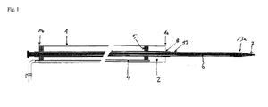
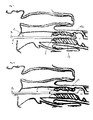
- FIG. 1 shows a catheter device according to the invention with a guide element 1, which has at its second end 1a, a first holding element 2, shown here as a simple suction cup, which is formed by a portion of the guide member 1, which is formed by a between guide means 8 and guide member 1 arranged seal 5 becomes.
- the extension piece 13 is arranged longitudinally displaceably in the guide device 8.
- the extension piece 13 is guided into the uterus, in particular through the cervix.
- a stylet (not shown) which is connected to a stylet carrier which is arranged in the guide element 1, preferably in the guide device 8 and through the cross-sectional opening at the first end 1b of the guide element 1 is removable.
- the cross-sectional opening of the second end 13a of the extension piece 13 is covered by a stylet 7.
- the flexible line 3 (not shown) can be arranged in the guide device, in the embodiment shown in the extension piece 13, after the stylet 7 and the sliding element 6 are removed from the extension piece 13.
- the first holding element 2 is connected to a first actuating device 4, one end of which is accessible from the side of the first end 1b of the guide element 1.
- the first actuating device 4 is shown as a line which makes the first holding element 2 accessible from a region at the first end 1b of the guide element 1, for example in the form of the opening of the line forming the first actuating device 4, in the region of the first end 1b of the guide element 1.
- the first holding element 2 can form a balloon section which can be inflated by the first actuating device 4.
- the second end 1a of the guide element 1 can be closed except for the flexible conduit 3 and / or except for the extension piece 13, in order, for example, to move. with the seal 5 between guide element 1 and guide device 8, to form an inflatable annular balloon (not shown) at the second end 1a of the guide element 1, which has an end section closed except for the flexible line 3 and / or except for the extension piece 13.
- a sliding element 6 is shown in the extension piece 13, through which a stylet 7 is displaceable, so that, for example, after insertion of the extension piece 13 through the cervix the stylet 7 are removed from the extension piece 13 and the flexible conduit 3 in and through the Extension piece 13 can be performed.
- an inflatable balloon may be arranged at the distal end 13a of the extension piece 13, for example annularly around an outer portion at the second end 13a of the extension piece 13, and with a conduit along the extension piece 13 for supply and removal of medium be connected.
- the guide element 1 has a guide device 8, which is preferably arranged coaxially in the guide element 1, and in which the extension piece 13, in which the flexible conduit 3 is longitudinally displaceable, longitudinally displaceable and rotatable.
- the extension piece 13 preferably protrudes beyond the first end 1b of the guide member 1, and is accessible from the first end 1b side of the guide member 1 for rotation and / or longitudinal displacement, and optionally includes a manipulation means (not shown), such as a handle.
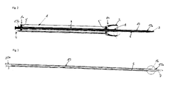
- FIG. 2 shows in sectional view the guide element 1 of the catheter device, at the second end 1a of which a first holding element 2 is arranged, which can be manipulated with a first actuating device 4.
- the first holding element 2 is a suction cup, by means of the first actuating device 4, which is for example a running along the guide member 1 line, a negative pressure can be applied.
- this first holding element 2 can be arranged at a terminal portion of the cervix Z, and this section is set by applying negative pressure to the first actuator 4 by negative pressure on the first holding element 2, so that by applying train on the guide element 1, a tensile load the cervix Z can be exerted away from the uterine U.
- the guide element 1 has a central and / or coaxially arranged guide device 8, which is sealed with seals 5 against the guide element 1.
- an extension piece 13 is arranged longitudinally displaceable, through which the flexible conduit 3 (not shown) after removal of the coupled with the sliding element 6 Mandrins 7 can be arranged.
- the first holding element 2 is designed as a suction cup arranged on the second end 1a of the guide element 1 through the seal 5 arranged on the second end 1a of the guide element 1, which is arranged between guide element 1 and guide device 8 and a section of the guide element 1 delimits.
- the holding element 2 is accessible from the first end of the guide element 1 by the first actuating device 4 designed as a line, for example by applying negative pressure in the method according to the invention for engagement with a terminal section of the cervix Z.
- the flexible line 3 is according to the generally preferred embodiment arranged in the guide element 1 guide means, in particular by the in the Guide device 8 longitudinally displaceable arranged extension piece 13 can be arranged longitudinally displaceable.
- a stylet 7 is preferably arranged on the second end 13a of the extension piece 13, which can be removed by means of its sliding element 6 through the first end 1b of the guide element 1 or through the first end 13b of the attachment piece 13 arranged thereon ,
- the guide device 8 extends into the region of the first holding element 2 or into the region of a second holding element 9 of the attachment piece 13.
- the flexible conduit 3 is for example so rigid that it can be advanced without additional stiffening from the guide element 1 or from the extension piece 13 and sufficiently flexible or semi-flexible that, for example, when contacting a tissue surface, a bend by a maximum of 90 °, preferably occurs at 10 to 45 ° and the flexible line 3 evades with further feed.
- a suction cup which forms a first holding element 2 is preferably formed by a funnel-shaped or bell-shaped material arranged on the second end 1a of the guide element 1, which material is rigid or flexible, e.g. can be elastic.
- the flexible conduit 3 has a length sufficient to advance in the process its distal end 3a at least through the cervix into the uterus, preferably to or into the utero-tubal connection, while the guide element 1 to or is guided by the cervix Z when a first holding element 2 and / or a second holding element 9 is arranged at a terminal portion of the cervix Z, in particular when a train directed away from the uterus rests against the cervix.
- an extension piece (not shown, see FIGS. 5 to 8 ), which is preferably sized so that it can traverse the cervix.
- the flexible conduit 3 exits in its arrangement by the guide member 1 at the second end of the extension piece.
- FIG. 3 shows only one extension piece 13 in detail, in which a sliding element 6 is arranged with a terminal mandrel 7, which projects beyond the second end 13 a of the extension piece 13.
- the extension piece 13 optionally has at its second end 13a an outer peripheral annular inflatable balloon 16 which is connected by means of a conduit extending along the extension 13 for the inflation and deflation of medium.
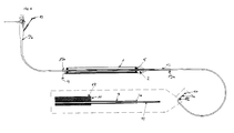
- FIG. 4 shows the catheter apparatus in a preferred embodiment, in which a detection device, which corresponds for example to that of a conventional endoscope, along the flexible conduit 3 is arranged, and moreover within the flexible conduit 3, a second flexible conduit 10 is arranged, which is longitudinally displaceable within the flexible conduit 3 is.
- the flexible conduit 3 is longitudinally displaceably guided within a shell 12.
- the sensor surface 11 is connected to a data line (not shown) of the detection device in a jacket 12, in which the flexible line 3 is arranged with longitudinally displaceably arranged second flexible line 10.
- the flexible conduit 3 may be longitudinally displaceable in the jacket 12 and moreover ends at a distance in front of the sensor surface 11, or flush with the sensor surface 11, while the second flexible conduit 10 is preferably advanceable from the flexible conduit 3, and the outlet opening of the second flexible Line 10 is slidable to a distance in front of the sensor surface 11, for example, for the arrangement of the outlet opening of the second flexible conduit 10 within the isthmus I of the fallopian tube E.
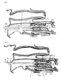
- FIG. 5 shows the guide element 1, which has a first holding element 2 in the form of a suction cup connected to a first actuating device 4 on the example of the genital tract of a cow shown schematically.
- a first holding element 2 in the form of a suction cup connected to a first actuating device 4 on the example of the genital tract of a cow shown schematically.
- an extension piece 13 is arranged, the second end 13 a is arranged at a distance in front of the second end 1 a of the guide member 1, while a portion of the extension piece 13 is disposed within the guide member 1, so that the first end 13 b of the extension piece 13 is accessible from the first end 1b of the guide element 1 and is provided, for example, at its first end 13b with a manipulation device, for example a handle.
- the extension 13 is suitable for placement through the cervix Z when the first actuator 4 of the guide member 1 is located at a terminal portion of the cervix Z, eg, as shown at the vaginal terminal portion.
- the fixation of a terminal section of the cervix Z takes place here by the engagement of the first holding element 2 at a terminal portion of the cervix Z, here by applying negative pressure to the first holding device 2 by the first actuator 4, which is a line for applying negative pressure and therefore connected to a vacuum source.
- the second end 13a of the hub 13 is positioned in the area of the uterus U after passage through the cervix Z.
- the other elements of the device according to the invention are in the FIGS. 5 to 8 not shown, in particular not the flexible conduit 3, a guide device 8 and a detection device.
- FIG. 6 shows an embodiment in which at the second end 1a of the guide member 1, an extension piece 13 is fixed, whose axis is located substantially in the axis of the guide member 1.
- the first holding element 2 is arranged on the second end 1a of the guide element 1 and is engaged by actuation of the first actuating device 4 with the vaginal-side terminal portion of the cervix Z.
- the extension piece 13 is arranged through the cervix Z and has at its second end 13a a second holding element 9, which is connected to a second actuating device 15, which is arranged along the extension piece 13 and the guide element 1.
- the second retaining element 9 can have expandable clips and / or an inflatable annular balloon 16 against the longitudinal axis of the attachment piece 13.
- the second holding element 9 By operating the second holding element 9 by means of the second actuating device 15, the second holding element 9 engages the second end 13 a of the extension piece 13 with the uterus side terminal portion of the cervix Z in engagement.
- the second holding element 9 is in addition to or in alternative to the first holding device 2 with this terminal end portion of the cervix Z into engagement.
- the second holding member 9 is an annular inflatable about the second end 13 a of the endpiece 13 balloon 16, not only with the terminal uterine-side portion of the cervix Z engages, or the transmission of a tensile force on the cervix Z by moving the guide member 1 in the direction of the uterus U away allows (in FIG.
- a line 14 is correspondingly preferably arranged along the guide element 1 and the extension piece 13 and terminates in a portion of the extension piece 13, which on the second end 13 a of the extension piece 13 facing side of the second Retaining element 9 is located.
- the first holding element 9 may also be formed by two or more suction cups, eg cup or ring-shaped bells.
- FIG. 7 shows a further embodiment of the device in which the extension piece 13 has an external thread with which the extension piece 13 can pass more easily by rotation through the cervix Z.
- the extension piece 13 at its second end 13a have a thickening, which preferably corresponds at least to the height of the external thread.
Landscapes
- Health & Medical Sciences (AREA)
- Life Sciences & Earth Sciences (AREA)
- Veterinary Medicine (AREA)
- Surgery (AREA)
- Animal Behavior & Ethology (AREA)
- Public Health (AREA)
- General Health & Medical Sciences (AREA)
- Reproductive Health (AREA)
- Engineering & Computer Science (AREA)
- Nuclear Medicine, Radiotherapy & Molecular Imaging (AREA)
- Heart & Thoracic Surgery (AREA)
- Medical Informatics (AREA)
- Molecular Biology (AREA)
- Biomedical Technology (AREA)
- Pregnancy & Childbirth (AREA)
- Gynecology & Obstetrics (AREA)
- Transplantation (AREA)
- Animal Husbandry (AREA)
- Wood Science & Technology (AREA)
- Zoology (AREA)
- Media Introduction/Drainage Providing Device (AREA)
- Materials For Medical Uses (AREA)
Applications Claiming Priority (1)
| Application Number | Priority Date | Filing Date | Title |
|---|---|---|---|
| DE102009047423A DE102009047423A1 (de) | 2009-12-02 | 2009-12-02 | Kathetervorrichtung |
Publications (3)
| Publication Number | Publication Date |
|---|---|
| EP2329793A2 true EP2329793A2 (fr) | 2011-06-08 |
| EP2329793A3 EP2329793A3 (fr) | 2011-09-21 |
| EP2329793B1 EP2329793B1 (fr) | 2015-04-22 |
Family
ID=43648705
Family Applications (1)
| Application Number | Title | Priority Date | Filing Date |
|---|---|---|---|
| EP20100193566 Not-in-force EP2329793B1 (fr) | 2009-12-02 | 2010-12-02 | Cathéter pour insémination artificielle |
Country Status (2)
| Country | Link |
|---|---|
| EP (1) | EP2329793B1 (fr) |
| DE (1) | DE102009047423A1 (fr) |
Cited By (2)
| Publication number | Priority date | Publication date | Assignee | Title |
|---|---|---|---|---|
| WO2020077122A1 (fr) * | 2018-10-10 | 2020-04-16 | Plessala Kirby J | Système et procédé d'insémination intra-utérine |
| US12539024B2 (en) | 2020-09-03 | 2026-02-03 | InnoMed Five, LLC | Medical device for female reproductive health and method of use |
Families Citing this family (1)
| Publication number | Priority date | Publication date | Assignee | Title |
|---|---|---|---|---|
| DE102021001654A1 (de) | 2021-03-29 | 2022-09-29 | Hans-Joachim Froböse | Vorrichtung und Verfahren zum lmplantieren einer befruchteten Eizelle oder eines Embryos |
Citations (5)
| Publication number | Priority date | Publication date | Assignee | Title |
|---|---|---|---|---|
| EP0214043A1 (fr) | 1985-08-19 | 1987-03-11 | Etablissement public dit: INSTITUT NATIONAL DE LA RECHERCHE AGRONOMIQUE | Instrument et procédé pour l'insémination artificielle, la transplantation d'embryons in-utéro ou le prélèvement de liquide folliculaire par voie transpéritonéale chez les animaux |
| US4654025A (en) | 1984-05-04 | 1987-03-31 | Robert Cassou | Artificial insemination apparatus |
| DE29703451U1 (de) | 1997-02-26 | 1998-06-25 | Minitüb Abfüll- und Labortechnik GmbH & Co KG, 84184 Tiefenbach | Besamungskatheter, insbesondere für Schweine |
| EP1177776B1 (fr) | 2000-01-20 | 2004-05-06 | Universidad de Murcia | Dispositif et methode permettant d'introduire et/ou de prelever des fluides a l'interieur de l'uterus d'un animal |
| DE19606925B4 (de) | 1995-02-13 | 2006-03-23 | Schnorrenberg, Arno | Besteck zur künstlichen Besamung von Elefanten und dessen Verwendung |
Family Cites Families (5)
| Publication number | Priority date | Publication date | Assignee | Title |
|---|---|---|---|---|
| US5558636A (en) * | 1995-05-09 | 1996-09-24 | Curators Of The University Of Missouri | Method of effecting embryo transplant |
| US5624399A (en) * | 1995-09-29 | 1997-04-29 | Ackrad Laboratories, Inc. | Catheter having an intracervical/intrauterine balloon made from polyurethane |
| US6117068A (en) * | 1995-10-19 | 2000-09-12 | Elite Genetics, Inc | Artificial insemination system |
| DE60014440T2 (de) * | 2000-01-03 | 2005-11-17 | Ibérica de Reproducción Asistida, S.L. | Vorrichtung zur künstlichen befruchtung von schweinen |
| CA2428526A1 (fr) * | 2000-11-03 | 2002-05-10 | Continental Plastic Corp. | Dispositif d'insemination artificielle transcervicale et de transfert d'embryon |
-
2009
- 2009-12-02 DE DE102009047423A patent/DE102009047423A1/de not_active Withdrawn
-
2010
- 2010-12-02 EP EP20100193566 patent/EP2329793B1/fr not_active Not-in-force
Patent Citations (5)
| Publication number | Priority date | Publication date | Assignee | Title |
|---|---|---|---|---|
| US4654025A (en) | 1984-05-04 | 1987-03-31 | Robert Cassou | Artificial insemination apparatus |
| EP0214043A1 (fr) | 1985-08-19 | 1987-03-11 | Etablissement public dit: INSTITUT NATIONAL DE LA RECHERCHE AGRONOMIQUE | Instrument et procédé pour l'insémination artificielle, la transplantation d'embryons in-utéro ou le prélèvement de liquide folliculaire par voie transpéritonéale chez les animaux |
| DE19606925B4 (de) | 1995-02-13 | 2006-03-23 | Schnorrenberg, Arno | Besteck zur künstlichen Besamung von Elefanten und dessen Verwendung |
| DE29703451U1 (de) | 1997-02-26 | 1998-06-25 | Minitüb Abfüll- und Labortechnik GmbH & Co KG, 84184 Tiefenbach | Besamungskatheter, insbesondere für Schweine |
| EP1177776B1 (fr) | 2000-01-20 | 2004-05-06 | Universidad de Murcia | Dispositif et methode permettant d'introduire et/ou de prelever des fluides a l'interieur de l'uterus d'un animal |
Cited By (2)
| Publication number | Priority date | Publication date | Assignee | Title |
|---|---|---|---|---|
| WO2020077122A1 (fr) * | 2018-10-10 | 2020-04-16 | Plessala Kirby J | Système et procédé d'insémination intra-utérine |
| US12539024B2 (en) | 2020-09-03 | 2026-02-03 | InnoMed Five, LLC | Medical device for female reproductive health and method of use |
Also Published As
| Publication number | Publication date |
|---|---|
| DE102009047423A1 (de) | 2011-06-09 |
| EP2329793A3 (fr) | 2011-09-21 |
| EP2329793B1 (fr) | 2015-04-22 |
Similar Documents
| Publication | Publication Date | Title |
|---|---|---|
| EP0526669B1 (fr) | Jeu d'instruments pour le transfert d'embryons utérins et pour l'insémination intrautérine | |
| DE69128824T2 (de) | Injektionskatheter | |
| DE4419726C2 (de) | Vorrichtung zur künstlichen Befruchtung und Embryonenüberführung | |
| US20250185897A1 (en) | Introducer Sheaths for Endoscopes and Related Methods | |
| DE60010455T2 (de) | Vorrichtung und verfahren zum einbringen oder entnehmen von flüssigkeiten aus dem inneren des uterus eines tieres | |
| DE60311414T2 (de) | Katheter mit geformter rampe für führungsdraht | |
| DE60002059T2 (de) | Chirurgische zange | |
| DE60222735T2 (de) | Intrauterin-Mikrokatheter | |
| DE10325086A1 (de) | Endoskopgerät | |
| DE2436666A1 (de) | Applikatorvorrichtung zum anlegen eines verschlussrings an anatomischen rohrfoermigen strukturen | |
| JPH04224766A (ja) | 体腔に出入りするためのカテーテル及びその使用方法 | |
| DE3909290A1 (de) | Umhuelltes endoskop | |
| EP2329793B1 (fr) | Cathéter pour insémination artificielle | |
| DE112015000997T5 (de) | Stenteinbringungssystem und Endoskopsystem | |
| EP1894529A2 (fr) | Dispositif destiné à l'introduction d'au moins un élément d'ancrage dans un espace creux d'un être vivant | |
| WO2018010034A1 (fr) | Dispositif d'utilisation de soutien pendant la colonoscopie, en particulier permettant de fixer et, de préférence, d'étanchéifier un endoscope dans la zone du canal anal et/ou du rectum | |
| EP1721579B1 (fr) | Cathéter pour transfert d'embryon | |
| US8323209B2 (en) | Chorionic villus sampling catheter | |
| DE19629624C2 (de) | Geburtshilfeextraktor | |
| EP2529695B1 (fr) | Endoscope pour transfert de gamètes | |
| DE69621433T2 (de) | Transcervicale infusionspipette | |
| EP3369397B1 (fr) | Dispositif de manipulation par ultrasons d'organes de reproduction femelles des grands mammifères | |
| DE60117608T2 (de) | Vorrichtung für transzervikale artifizielle insemination und embryonentransfer | |
| DE69819199T2 (de) | Einrichtung zum eindringen in den uterus eines tieres | |
| DE2328175C3 (de) | Tuben-Occlusivpessar und Vorrichtung zum Setzen des Tuben-Occlusivpessars |
Legal Events
| Date | Code | Title | Description |
|---|---|---|---|
| PUAI | Public reference made under article 153(3) epc to a published international application that has entered the european phase |
Free format text: ORIGINAL CODE: 0009012 |
|
| AK | Designated contracting states |
Kind code of ref document: A2 Designated state(s): AL AT BE BG CH CY CZ DE DK EE ES FI FR GB GR HR HU IE IS IT LI LT LU LV MC MK MT NL NO PL PT RO RS SE SI SK SM TR |
|
| AX | Request for extension of the european patent |
Extension state: BA ME |
|
| RIN1 | Information on inventor provided before grant (corrected) |
Inventor name: RATH, DETLEF Inventor name: GROSSFELD, RUDOLF |
|
| PUAL | Search report despatched |
Free format text: ORIGINAL CODE: 0009013 |
|
| AK | Designated contracting states |
Kind code of ref document: A3 Designated state(s): AL AT BE BG CH CY CZ DE DK EE ES FI FR GB GR HR HU IE IS IT LI LT LU LV MC MK MT NL NO PL PT RO RS SE SI SK SM TR |
|
| AX | Request for extension of the european patent |
Extension state: BA ME |
|
| RIC1 | Information provided on ipc code assigned before grant |
Ipc: A61B 17/43 20060101ALI20110817BHEP Ipc: A61D 19/02 20060101AFI20110817BHEP |
|
| 17P | Request for examination filed |
Effective date: 20120322 |
|
| 17Q | First examination report despatched |
Effective date: 20120928 |
|
| GRAP | Despatch of communication of intention to grant a patent |
Free format text: ORIGINAL CODE: EPIDOSNIGR1 |
|
| INTG | Intention to grant announced |
Effective date: 20141201 |
|
| RIN1 | Information on inventor provided before grant (corrected) |
Inventor name: GROSSFELD, RUDOLF Inventor name: RATH, DETLEF |
|
| GRAS | Grant fee paid |
Free format text: ORIGINAL CODE: EPIDOSNIGR3 |
|
| GRAA | (expected) grant |
Free format text: ORIGINAL CODE: 0009210 |
|
| AK | Designated contracting states |
Kind code of ref document: B1 Designated state(s): AL AT BE BG CH CY CZ DE DK EE ES FI FR GB GR HR HU IE IS IT LI LT LU LV MC MK MT NL NO PL PT RO RS SE SI SK SM TR |
|
| REG | Reference to a national code |
Ref country code: GB Ref legal event code: FG4D Free format text: NOT ENGLISH |
|
| REG | Reference to a national code |
Ref country code: CH Ref legal event code: EP |
|
| REG | Reference to a national code |
Ref country code: AT Ref legal event code: REF Ref document number: 722727 Country of ref document: AT Kind code of ref document: T Effective date: 20150515 |
|
| REG | Reference to a national code |
Ref country code: IE Ref legal event code: FG4D Free format text: LANGUAGE OF EP DOCUMENT: GERMAN |
|
| REG | Reference to a national code |
Ref country code: DE Ref legal event code: R096 Ref document number: 502010009385 Country of ref document: DE Effective date: 20150603 |
|
| REG | Reference to a national code |
Ref country code: NL Ref legal event code: VDEP Effective date: 20150422 |
|
| REG | Reference to a national code |
Ref country code: LT Ref legal event code: MG4D |
|
| PG25 | Lapsed in a contracting state [announced via postgrant information from national office to epo] |
Ref country code: NL Free format text: LAPSE BECAUSE OF FAILURE TO SUBMIT A TRANSLATION OF THE DESCRIPTION OR TO PAY THE FEE WITHIN THE PRESCRIBED TIME-LIMIT Effective date: 20150422 |
|
| PG25 | Lapsed in a contracting state [announced via postgrant information from national office to epo] |
Ref country code: ES Free format text: LAPSE BECAUSE OF FAILURE TO SUBMIT A TRANSLATION OF THE DESCRIPTION OR TO PAY THE FEE WITHIN THE PRESCRIBED TIME-LIMIT Effective date: 20150422 Ref country code: LT Free format text: LAPSE BECAUSE OF FAILURE TO SUBMIT A TRANSLATION OF THE DESCRIPTION OR TO PAY THE FEE WITHIN THE PRESCRIBED TIME-LIMIT Effective date: 20150422 Ref country code: PT Free format text: LAPSE BECAUSE OF FAILURE TO SUBMIT A TRANSLATION OF THE DESCRIPTION OR TO PAY THE FEE WITHIN THE PRESCRIBED TIME-LIMIT Effective date: 20150824 Ref country code: FI Free format text: LAPSE BECAUSE OF FAILURE TO SUBMIT A TRANSLATION OF THE DESCRIPTION OR TO PAY THE FEE WITHIN THE PRESCRIBED TIME-LIMIT Effective date: 20150422 Ref country code: NO Free format text: LAPSE BECAUSE OF FAILURE TO SUBMIT A TRANSLATION OF THE DESCRIPTION OR TO PAY THE FEE WITHIN THE PRESCRIBED TIME-LIMIT Effective date: 20150722 Ref country code: HR Free format text: LAPSE BECAUSE OF FAILURE TO SUBMIT A TRANSLATION OF THE DESCRIPTION OR TO PAY THE FEE WITHIN THE PRESCRIBED TIME-LIMIT Effective date: 20150422 |
|
| PG25 | Lapsed in a contracting state [announced via postgrant information from national office to epo] |
Ref country code: GR Free format text: LAPSE BECAUSE OF FAILURE TO SUBMIT A TRANSLATION OF THE DESCRIPTION OR TO PAY THE FEE WITHIN THE PRESCRIBED TIME-LIMIT Effective date: 20150723 Ref country code: IS Free format text: LAPSE BECAUSE OF FAILURE TO SUBMIT A TRANSLATION OF THE DESCRIPTION OR TO PAY THE FEE WITHIN THE PRESCRIBED TIME-LIMIT Effective date: 20150822 Ref country code: RS Free format text: LAPSE BECAUSE OF FAILURE TO SUBMIT A TRANSLATION OF THE DESCRIPTION OR TO PAY THE FEE WITHIN THE PRESCRIBED TIME-LIMIT Effective date: 20150422 Ref country code: LV Free format text: LAPSE BECAUSE OF FAILURE TO SUBMIT A TRANSLATION OF THE DESCRIPTION OR TO PAY THE FEE WITHIN THE PRESCRIBED TIME-LIMIT Effective date: 20150422 |
|
| REG | Reference to a national code |
Ref country code: DE Ref legal event code: R097 Ref document number: 502010009385 Country of ref document: DE |
|
| PG25 | Lapsed in a contracting state [announced via postgrant information from national office to epo] |
Ref country code: EE Free format text: LAPSE BECAUSE OF FAILURE TO SUBMIT A TRANSLATION OF THE DESCRIPTION OR TO PAY THE FEE WITHIN THE PRESCRIBED TIME-LIMIT Effective date: 20150422 Ref country code: DK Free format text: LAPSE BECAUSE OF FAILURE TO SUBMIT A TRANSLATION OF THE DESCRIPTION OR TO PAY THE FEE WITHIN THE PRESCRIBED TIME-LIMIT Effective date: 20150422 |
|
| PLBE | No opposition filed within time limit |
Free format text: ORIGINAL CODE: 0009261 |
|
| STAA | Information on the status of an ep patent application or granted ep patent |
Free format text: STATUS: NO OPPOSITION FILED WITHIN TIME LIMIT |
|
| PG25 | Lapsed in a contracting state [announced via postgrant information from national office to epo] |
Ref country code: RO Free format text: LAPSE BECAUSE OF NON-PAYMENT OF DUE FEES Effective date: 20150422 Ref country code: SK Free format text: LAPSE BECAUSE OF FAILURE TO SUBMIT A TRANSLATION OF THE DESCRIPTION OR TO PAY THE FEE WITHIN THE PRESCRIBED TIME-LIMIT Effective date: 20150422 Ref country code: PL Free format text: LAPSE BECAUSE OF FAILURE TO SUBMIT A TRANSLATION OF THE DESCRIPTION OR TO PAY THE FEE WITHIN THE PRESCRIBED TIME-LIMIT Effective date: 20150422 Ref country code: CZ Free format text: LAPSE BECAUSE OF FAILURE TO SUBMIT A TRANSLATION OF THE DESCRIPTION OR TO PAY THE FEE WITHIN THE PRESCRIBED TIME-LIMIT Effective date: 20150422 |
|
| 26N | No opposition filed |
Effective date: 20160125 |
|
| PG25 | Lapsed in a contracting state [announced via postgrant information from national office to epo] |
Ref country code: IT Free format text: LAPSE BECAUSE OF FAILURE TO SUBMIT A TRANSLATION OF THE DESCRIPTION OR TO PAY THE FEE WITHIN THE PRESCRIBED TIME-LIMIT Effective date: 20150422 |
|
| PG25 | Lapsed in a contracting state [announced via postgrant information from national office to epo] |
Ref country code: SI Free format text: LAPSE BECAUSE OF FAILURE TO SUBMIT A TRANSLATION OF THE DESCRIPTION OR TO PAY THE FEE WITHIN THE PRESCRIBED TIME-LIMIT Effective date: 20150422 Ref country code: BE Free format text: LAPSE BECAUSE OF NON-PAYMENT OF DUE FEES Effective date: 20151231 |
|
| PG25 | Lapsed in a contracting state [announced via postgrant information from national office to epo] |
Ref country code: LU Free format text: LAPSE BECAUSE OF FAILURE TO SUBMIT A TRANSLATION OF THE DESCRIPTION OR TO PAY THE FEE WITHIN THE PRESCRIBED TIME-LIMIT Effective date: 20151202 Ref country code: MC Free format text: LAPSE BECAUSE OF FAILURE TO SUBMIT A TRANSLATION OF THE DESCRIPTION OR TO PAY THE FEE WITHIN THE PRESCRIBED TIME-LIMIT Effective date: 20150422 |
|
| REG | Reference to a national code |
Ref country code: CH Ref legal event code: PL |
|
| GBPC | Gb: european patent ceased through non-payment of renewal fee |
Effective date: 20151202 |
|
| REG | Reference to a national code |
Ref country code: IE Ref legal event code: MM4A |
|
| REG | Reference to a national code |
Ref country code: FR Ref legal event code: ST Effective date: 20160831 |
|
| PG25 | Lapsed in a contracting state [announced via postgrant information from national office to epo] |
Ref country code: GB Free format text: LAPSE BECAUSE OF NON-PAYMENT OF DUE FEES Effective date: 20151202 Ref country code: CH Free format text: LAPSE BECAUSE OF NON-PAYMENT OF DUE FEES Effective date: 20151231 Ref country code: IE Free format text: LAPSE BECAUSE OF NON-PAYMENT OF DUE FEES Effective date: 20151202 Ref country code: LI Free format text: LAPSE BECAUSE OF NON-PAYMENT OF DUE FEES Effective date: 20151231 |
|
| PG25 | Lapsed in a contracting state [announced via postgrant information from national office to epo] |
Ref country code: FR Free format text: LAPSE BECAUSE OF NON-PAYMENT OF DUE FEES Effective date: 20151231 |
|
| REG | Reference to a national code |
Ref country code: AT Ref legal event code: MM01 Ref document number: 722727 Country of ref document: AT Kind code of ref document: T Effective date: 20151202 |
|
| PG25 | Lapsed in a contracting state [announced via postgrant information from national office to epo] |
Ref country code: BG Free format text: LAPSE BECAUSE OF FAILURE TO SUBMIT A TRANSLATION OF THE DESCRIPTION OR TO PAY THE FEE WITHIN THE PRESCRIBED TIME-LIMIT Effective date: 20150422 Ref country code: SM Free format text: LAPSE BECAUSE OF FAILURE TO SUBMIT A TRANSLATION OF THE DESCRIPTION OR TO PAY THE FEE WITHIN THE PRESCRIBED TIME-LIMIT Effective date: 20150422 Ref country code: AT Free format text: LAPSE BECAUSE OF NON-PAYMENT OF DUE FEES Effective date: 20151202 Ref country code: HU Free format text: LAPSE BECAUSE OF FAILURE TO SUBMIT A TRANSLATION OF THE DESCRIPTION OR TO PAY THE FEE WITHIN THE PRESCRIBED TIME-LIMIT; INVALID AB INITIO Effective date: 20101202 |
|
| PG25 | Lapsed in a contracting state [announced via postgrant information from national office to epo] |
Ref country code: SE Free format text: LAPSE BECAUSE OF FAILURE TO SUBMIT A TRANSLATION OF THE DESCRIPTION OR TO PAY THE FEE WITHIN THE PRESCRIBED TIME-LIMIT Effective date: 20150422 Ref country code: CY Free format text: LAPSE BECAUSE OF FAILURE TO SUBMIT A TRANSLATION OF THE DESCRIPTION OR TO PAY THE FEE WITHIN THE PRESCRIBED TIME-LIMIT Effective date: 20150422 |
|
| PG25 | Lapsed in a contracting state [announced via postgrant information from national office to epo] |
Ref country code: MT Free format text: LAPSE BECAUSE OF FAILURE TO SUBMIT A TRANSLATION OF THE DESCRIPTION OR TO PAY THE FEE WITHIN THE PRESCRIBED TIME-LIMIT Effective date: 20150422 Ref country code: TR Free format text: LAPSE BECAUSE OF FAILURE TO SUBMIT A TRANSLATION OF THE DESCRIPTION OR TO PAY THE FEE WITHIN THE PRESCRIBED TIME-LIMIT Effective date: 20150422 |
|
| PG25 | Lapsed in a contracting state [announced via postgrant information from national office to epo] |
Ref country code: MK Free format text: LAPSE BECAUSE OF FAILURE TO SUBMIT A TRANSLATION OF THE DESCRIPTION OR TO PAY THE FEE WITHIN THE PRESCRIBED TIME-LIMIT Effective date: 20150422 |
|
| PG25 | Lapsed in a contracting state [announced via postgrant information from national office to epo] |
Ref country code: AL Free format text: LAPSE BECAUSE OF FAILURE TO SUBMIT A TRANSLATION OF THE DESCRIPTION OR TO PAY THE FEE WITHIN THE PRESCRIBED TIME-LIMIT Effective date: 20150422 |
|
| PGFP | Annual fee paid to national office [announced via postgrant information from national office to epo] |
Ref country code: DE Payment date: 20211130 Year of fee payment: 12 |
|
| REG | Reference to a national code |
Ref country code: DE Ref legal event code: R119 Ref document number: 502010009385 Country of ref document: DE |
|
| PG25 | Lapsed in a contracting state [announced via postgrant information from national office to epo] |
Ref country code: DE Free format text: LAPSE BECAUSE OF NON-PAYMENT OF DUE FEES Effective date: 20230701 |