EP2330006A1 - Zugbremsvorrichtung - Google Patents
Zugbremsvorrichtung Download PDFInfo
- Publication number
- EP2330006A1 EP2330006A1 EP08791560A EP08791560A EP2330006A1 EP 2330006 A1 EP2330006 A1 EP 2330006A1 EP 08791560 A EP08791560 A EP 08791560A EP 08791560 A EP08791560 A EP 08791560A EP 2330006 A1 EP2330006 A1 EP 2330006A1
- Authority
- EP
- European Patent Office
- Prior art keywords
- switch
- valve
- electromagnetic
- circuit
- compressed air
- Prior art date
- Legal status (The legal status is an assumption and is not a legal conclusion. Google has not performed a legal analysis and makes no representation as to the accuracy of the status listed.)
- Granted
Links
Images


Classifications
-
- B—PERFORMING OPERATIONS; TRANSPORTING
- B60—VEHICLES IN GENERAL
- B60T—VEHICLE BRAKE CONTROL SYSTEMS OR PARTS THEREOF; BRAKE CONTROL SYSTEMS OR PARTS THEREOF, IN GENERAL; ARRANGEMENT OF BRAKING ELEMENTS ON VEHICLES IN GENERAL; PORTABLE DEVICES FOR PREVENTING UNWANTED MOVEMENT OF VEHICLES; VEHICLE MODIFICATIONS TO FACILITATE COOLING OF BRAKES
- B60T17/00—Component parts, details, or accessories of power brake systems not covered by groups B60T8/00, B60T13/00 or B60T15/00, or presenting other characteristic features
- B60T17/18—Safety devices; Monitoring
- B60T17/22—Devices for monitoring or checking brake systems; Signal devices
- B60T17/228—Devices for monitoring or checking brake systems; Signal devices for railway vehicles
-
- B—PERFORMING OPERATIONS; TRANSPORTING
- B60—VEHICLES IN GENERAL
- B60T—VEHICLE BRAKE CONTROL SYSTEMS OR PARTS THEREOF; BRAKE CONTROL SYSTEMS OR PARTS THEREOF, IN GENERAL; ARRANGEMENT OF BRAKING ELEMENTS ON VEHICLES IN GENERAL; PORTABLE DEVICES FOR PREVENTING UNWANTED MOVEMENT OF VEHICLES; VEHICLE MODIFICATIONS TO FACILITATE COOLING OF BRAKES
- B60T13/00—Transmitting braking action from initiating means to ultimate brake actuator with power assistance or drive; Brake systems incorporating such transmitting means, e.g. air-pressure brake systems
- B60T13/10—Transmitting braking action from initiating means to ultimate brake actuator with power assistance or drive; Brake systems incorporating such transmitting means, e.g. air-pressure brake systems with fluid assistance, drive, or release
- B60T13/66—Electrical control in fluid-pressure brake systems
- B60T13/665—Electrical control in fluid-pressure brake systems the systems being specially adapted for transferring two or more command signals, e.g. railway systems
-
- B—PERFORMING OPERATIONS; TRANSPORTING
- B60—VEHICLES IN GENERAL
- B60T—VEHICLE BRAKE CONTROL SYSTEMS OR PARTS THEREOF; BRAKE CONTROL SYSTEMS OR PARTS THEREOF, IN GENERAL; ARRANGEMENT OF BRAKING ELEMENTS ON VEHICLES IN GENERAL; PORTABLE DEVICES FOR PREVENTING UNWANTED MOVEMENT OF VEHICLES; VEHICLE MODIFICATIONS TO FACILITATE COOLING OF BRAKES
- B60T8/00—Arrangements for adjusting wheel-braking force to meet varying vehicular or ground-surface conditions, e.g. limiting or varying distribution of braking force
- B60T8/18—Arrangements for adjusting wheel-braking force to meet varying vehicular or ground-surface conditions, e.g. limiting or varying distribution of braking force responsive to vehicle weight or load, e.g. load distribution
- B60T8/1893—Arrangements for adjusting wheel-braking force to meet varying vehicular or ground-surface conditions, e.g. limiting or varying distribution of braking force responsive to vehicle weight or load, e.g. load distribution especially adapted for railway vehicles
-
- B—PERFORMING OPERATIONS; TRANSPORTING
- B60—VEHICLES IN GENERAL
- B60T—VEHICLE BRAKE CONTROL SYSTEMS OR PARTS THEREOF; BRAKE CONTROL SYSTEMS OR PARTS THEREOF, IN GENERAL; ARRANGEMENT OF BRAKING ELEMENTS ON VEHICLES IN GENERAL; PORTABLE DEVICES FOR PREVENTING UNWANTED MOVEMENT OF VEHICLES; VEHICLE MODIFICATIONS TO FACILITATE COOLING OF BRAKES
- B60T8/00—Arrangements for adjusting wheel-braking force to meet varying vehicular or ground-surface conditions, e.g. limiting or varying distribution of braking force
- B60T8/32—Arrangements for adjusting wheel-braking force to meet varying vehicular or ground-surface conditions, e.g. limiting or varying distribution of braking force responsive to a speed condition, e.g. acceleration or deceleration
- B60T8/321—Arrangements for adjusting wheel-braking force to meet varying vehicular or ground-surface conditions, e.g. limiting or varying distribution of braking force responsive to a speed condition, e.g. acceleration or deceleration deceleration
- B60T8/3235—Systems specially adapted for rail vehicles
Definitions
- the present invention relates to a train braking device.
- the air brake controller In a train braking device having an air brake controller, the air brake controller generates a predetermined signal based on a service brake command and an emergency brake command, and an electromagnetic valve generates a pneumatic signal corresponding to the predetermined signal, so that a predetermined brake cylinder force can be obtained.
- a circuit for service brake control and a circuit for slide control are common in an air brake controller.
- a circuit for emergency brake is independent of the circuit for service brake control and that for slide control.
- an electromagnetic valve for emergency brake is independent of the electromagnetic valve for service brake control and that for slide control.
- Patent Document 1 Japanese Patent Application Laid-open No. 2001-018784
- the present invention has been achieved in view of the above problems and an object of the present invention is to provide a train braking device capable of further improving reliability of an air brake.
- the train braking device of the present invention includes an electromagnetic valve unit having a supply valve for supplying supplied compressed air to the brake cylinder and an exhaust valve for adjusting a pressure of the supplied compressed air.
- the controller includes an electromagnetic-valve drive circuit, which has a first switch circuit that a first switch for slide control is connected in parallel to ends of a serially connected circuit of a first switch for emergency brake and a first switch for service brake control with its one end being connected to a circuit power supply and the other end being connected to the supply valve, and a second switch circuit that a second switch for slide control is connected in parallel to ends of a serially connected circuit of a second switch for emergency brake and a second switch for service brake control with its one end being connected to the other end of the first switch circuit and the other end being connected to the exhaust valve.
- the train braking device includes a supply valve and an exhaust valve connected to two switch circuits that a switch for slide control is connected in parallel to a serially connected circuit of a switch for emergency brake and a switch for service brake control, and the exhaust valve is operated in cooperation with the supply valve.
- FIG. 1 is an example of a configuration of a train braking device according to a first embodiment of the present invention.
- a train braking device 100 shown in Fig. 1 includes, as its main constituent units, a controller 1, a load compensating valve 2, an AMV (Apply Magnet Valve: supply valve) 20, an RMV (Release Magnet Valve: exhaust valve) 21, a relay valve 9, and a brake cylinder 10.
- the constituent units connected to the controller 1 are shown so as to be symmetrical to each other with respect to the load compensating valve 2. This is because a first constituent unit connected to the controller 1 controls a brake of first carriage of each vehicle and a second constituent unit controls a brake of a second carriage.
- the controller 1 receives a service brake command 11 transmitted from a brake command unit.
- the controller 1 also receives an emergency brake command 12 by a different line from that of the service brake command 11.
- the load compensating valve 2 is arranged at front and rear carriages of each vehicle and supplies an output pressure 2a of compressed air directly to the relay valve 9 for generating an emergency brake.
- the AMV 20 supplies the output pressure 2a of the supplied compressed air to the brake cylinder 10.
- the RMV 21 adjusts the output pressure 2a of the supplied compressed air.
- a constituent unit of the AMV 20 and the RMV 21 is called an electromagnetic valve unit.
- the relay valve 9 is used to improve the response of a brake cylinder pressure 9a and amplifies compressed air supplied from the AMV 20 and the RMV 21 (hereinafter, "pressure control signal") 3b so as to have a predetermined pressure.
- An air tank (not shown) is connected to the relay valve 9. Because compressed air is reserved in the air tank, the relay valve 9 can amplify the pressure control signal 3b to generate the brake cylinder pressure 9a for operating the brake cylinder 10.
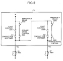
- Fig. 2 is an example of a configuration of an electromagnetic-valve drive circuit according to the first embodiment.
- An electromagnetic-valve drive circuit 1a is a part of an internal circuit in the controller 1 and is a circuit that drives the AMV 20 and the RMV 21.
- the electromagnetic-valve drive circuit 1a includes, as its main constituent units, a first switch SW1 for slide control, a second switch SW4 for slide control, a first switch SW2 for emergency brake, a second switch SW5 for emergency brake, a first switch SW3 for service brake control, a second switch SW6 for service brake control, a contact S1 for an H/W timer, a contact S2 for an H/W timer, and a circuit power supply P.
- the AMV 20 and the RMV 21 correspond to the AMV 20 and the RMV 21 shown in Fig. 1 .
- the contact S1 for an H/W timer and the contact S2 for an H/W timer suspend a wheel slide control safety function and a wheel slide control operation to protect electromagnetic valves from excessive abrasion and recover the wheel slide control without stopping a train.
- the electromagnetic-valve drive circuit 1a includes a first switch circuit that the first switch SW1 for slide control or a serially connected circuit of the first switch SW1 for slide control and the contact S1 for an H/W timer is connected in parallel to ends of a serially connected circuit of the first switch SW2 for emergency brake and the first switch SW3 for service brake control.
- the electromagnetic-valve drive circuit 1a also includes a second switch circuit that the second switch SW4 for slide control or a serially connected circuit of the second switch SW4 for slide control and the contact S2 for an H/W timer is connected in parallel to ends of a serially connected circuit of the second switch for emergency brake and the second switch for service brake control. While a serially connected circuit of a switch for emergency brake and a switch for service brake control is shown as an example, the switch included in the serially connected circuit is not limited to only the switch for emergency brake and the switch for service brake control.
- One end of the first switch circuit is connected to the circuit power supply P and the other end is connected to the AMV 20.
- One end of the second switch circuit is connected to the first switch circuit and the other end is connected to the RMV 21.
- Such a configuration allows slide control to be independent of emergency braking and service brake control and the RMV 21 to be driven in cooperation with the AMV 20. For example, when a contact of the first switch SW1 for slide control is closed, a current of the circuit power supply P is supplied to the second switch circuit and the second switch circuit can drive the RMV 21.
- a predetermined logic table is set in the controller 1 in advance, and the controller 1 opens or closes the first switch SW3 for service brake control and the second switch SW6 for service brake control based on the logic table.
- a second mode of supplying compressed air and a fifth mode of exhausting compressed air are defined so that the brake cylinder pressure 9a necessary for service brake control, slide control, and emergency brake output can be obtained.
- the logic table is used to control the AMV 20 or the RMV 21 in a pressurized or unpressurized manner.
- the electromagnetic-valve drive circuit 1a When the emergency brake command 12 is outputted, the electromagnetic-valve drive circuit 1a forcibly opens the first switch SW2 for emergency brake and the second switch SW5 for emergency brake. Because the first switch SW1 for slide control and the second switch SW4 for slide control are open, all of the electromagnetic valves become unpressurized because the circuit power supply P is not supplied thereto.
- the train braking device 100 then supplies the output pressure 2a from the load compensating valve 2 to the relay valve 9 to generate an emergency brake.
- the electromagnetic-valve drive circuit 1a opens or closes the first switch SW1 for slide control and the second switch SW4 for slide control based on the logic table to drive the AMV 20 or the RMV 21.
- the electromagnetic-valve drive circuit 1a can perform service brake control or generate an emergency brake although the first switch SW1 for slide control and the second switch SW4 for slide control are opened.
- the electromagnetic-valve drive circuit 1a that includes the first switch circuit and the second switch circuit makes the RMV 21 cooperate with the AMV 20.
- emergency electromagnetic valves and switching electromagnetic valves without using emergency electromagnetic valves and switching electromagnetic valves and without separating a circuit for emergency brake from a switch for slide control and for service brake, emergency braking, slide control, and service brake control can be performed.
- the emergency electromagnetic valve is not required, the train braking device 100 can be made compact and lightweight, materials for the device can be reduced, and costs can be saved. Because the number of parts is reduced, the reliability of the train braking device 100 is improved and it can be used for a long period of time.
- a train braking device 300 uses four types of magnet valves for controlling the brake cylinder pressure 9a finely.
- Fig. 3 is an example of a configuration of the train braking device according to the second embodiment.
- the train braking device 300 shown in Fig. 3 includes, as its main constituent units, the controller 1, the load compensating valve 2, an AMVH (Apply Magnet Valve High: first supply valve) 4, an AMVL (Apply Magnet Valve Low: second supply valve) 5, an RMVH (Release Magnet Valve High: first exhaust valve) 6, an RMVL (Release Magnet Valve Low: second exhaust valve) 7, the relay valve 9, and the brake cylinder 10.
- AMVH Apply Magnet Valve High: first supply valve
- AMVL Apply Magnet Valve Low: second supply valve
- RMVH Release Magnet Valve High: first exhaust valve
- RMVL Release Magnet Valve Low: second exhaust valve
- the AMVH 4 supplies the output pressure 2a of supplied compressed air to the brake cylinder 10.
- the RMVH 6 adjusts the output pressure 2a of the supplied compressed air.
- the AMVL 5 supplies the output pressure 2a of the compressed air so as to be lower than that of the AMVH 4.
- the RMVL 7 adjusts the output pressure 2a of the compressed air so as to be lower than that of the RMVH 6.
- the relay valve 9 is used to improve the response of the brake cylinder pressure 9a and amplifies the pressure control signal 3b supplied from the AMVH 4, the AMVL 5, the RMVH 6, and the RMVL 7 so as to have a predetermined pressure.
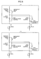
- Fig. 4 is an example of a configuration of an electromagnetic-valve drive circuit according to the second embodiment.
- a first electromagnetic-valve drive circuit 1b and a second electromagnetic-valve drive circuit 1c are a part of an internal circuit of the controller 1 and for driving the AMVH 4, the AMVL 5, the RMVH 6, and the RMVL 7.
- Each of the first electromagnetic-valve drive circuit 1b and the second electromagnetic-valve drive circuit 1c includes, as its main constituent units, the first switch SW1 for slide control, the second switch SW4 for slide control, the first switch SW2 for emergency brake, the second switch SW5 for emergency brake, the first switch SW3 for service brake control, the second switch SW6 for service brake control, the contact S1 for an H/W timer, the contact S2 for an H/W timer, and the circuit power supply P.
- the AMVH 4, the AMVL 5, the RMVH 6, and the RMVL 7 shown in Fig. 4 correspond to the AMVH 4, the AMVL 5, RMVH 6, and the RMVL 7 shown in Fig. 3 , respectively.
- Each of the first electromagnetic-valve drive circuit 1b and the second electromagnetic-valve drive circuit 1c includes a first switch circuit that the first switch SW1 for slide control or a serially connected circuit of the first switch SW1 for slide control and the contact S1 for an H/W timer is connected in parallel to ends of a serially connected circuit of the first switch SW2 for emergency brake and the first switch SW3 for service brake control.
- Each of the first electromagnetic-valve drive circuit 1b and the second electromagnetic-valve drive circuit 1c also includes a second switch circuit that the second switch SW4 for slide control or a serially connected circuit of the second switch SW4 for slide control and the contact S2 for an H/W timer is connected in parallel to ends of a serially connected circuit of the second switch for emergency brake and the second switch for service brake control. While the serially connected circuit constituted by only the switch for emergency brake and the switch for service brake control is shown as an example, the present invention is not limited thereto.
- the first electromagnetic-valve drive circuit 1b In the first electromagnetic-valve drive circuit 1b, one end of the first switch circuit is connected to the circuit power supply P and the other end is connected to the AMVH 4. One end of the second switch circuit is connected to the first switch circuit and the other end is connected to the RMVH 6.
- the first electromagnetic-valve drive circuit 1b can cause slide control to be independent of emergency braking and service brake control and drive the RMVH 6 in cooperation with the AMVH 4. For example, a contact of the first switch SW1 for slide control is closed, a current of the circuit power supply P is supplied to the second switch circuit and the second switch circuit can drive the RMVH 6.
- the second electromagnetic-valve drive circuit 1c In the second electromagnetic-valve drive circuit 1c, one end of the first switch circuit is connected to the circuit power supply P and the other end is connected to the AMVL 5. One end of the second switch circuit is connected to the first switch circuit and the other end is connected to the RMVL 7.
- the second electromagnetic-valve drive circuit 1c can cause slide control to be independent of emergency braking and service brake control and drive the RMVL 7 in cooperation with the AMVL 5. For example, when a contact of the first switch SW1 for slide control is closed, the current of the circuit power supply P is supplied to the second switch circuit and the second switch circuit can drive the RMVL 7.
- the train braking device 300 feeds back the pressure control signal 3b and the brake cylinder pressure 9a to the controller 1. Therefore, the controller 1 drives the AMVH 4, the AMVL 5, the RMVH 6, and the RMVL 7 while recognizing states of the pressure control signal 3b and the brake cylinder pressure 9a.
- Fig. 6 is an example of an electromagnetic-valve drive circuit having a simplified circuit configuration.
- a first electromagnetic-valve drive circuit 1d and a second electromagnetic-valve drive circuit 1e shown in Fig. 6 are obtained by removing the second switch SW5 for emergency brake shown in Fig. 4 . Because a connected portion of the first switch SW2 for emergency brake and the first switch SW3 for service brake control is connected to the second switch SW6 for service brake control and the first switch SW1 for slide control is connected to the second switch SW4 for slide control, an emergency brake can be generated only by the switch SW2 for emergency brake.
- the circuit configuration can be simplified and at the time of emergency braking, the AMVH 4, the AMVL 5, the RMVH 6, and the RMVL 7 can be unpressurized in a synchronized manner.
- the electromagnetic-valve drive circuit 1a according to the first embodiment can be also simplified in a similar manner.
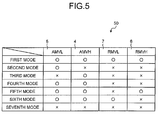
- Fig. 5 is an example of a logic table.
- a logic table 50 is set in the controller 1 in advance, and is used to adjust a magnitude of supply and exhaust of compressed air by combining operations of the AMVH 4, the AMVL 5, the RMVH 6, and the RMVL 7.
- the logic table 50 is constituted by an item indicating the name of each electromagnetic valve and an item indicating the magnitude of supply and exhaust of compressed air.
- the AMVH 4, the AMVL 5, the RMVH 6, and the RMVL 7 are shown in the item indicating the name of each electromagnetic valve.
- a first mode, a second mode, a third mode, a fourth mode, a fifth mode, a sixth mode, and a seventh mode are shown in the item indicating the magnitude of supply and exhaust of compressed air.
- the first mode indicates a released state of a service brake.
- the AMVH 4 and the AMVL 5 are closed and the RMVH 6 and the RMVL 7 are open.
- the output pressure 2a of compressed air is supplied.
- the AMVH 4 is open and the AMVL 5, the RMVH 6, and the RMVL 7 are closed.
- the output pressure 2a of compressed air is supplied moderately as compared to the second mode and the service brake is "finely adjusted".
- the AMVH 4 is in the pressurized state "o"
- the AMVL 5 is open and the AMVH 4, the RMVH 6, and the RMVL 7 are closed.
- the output pressure 2a of compressed air is exhausted.
- the RMVH 6 is open and the AMVH 4, the AMVL 5, and the RMVL 7 are closed.
- the output pressure 2a of compressed air is exhausted moderately as compared to the fifth mode.
- the RMVL 7 is open and the AMVH 4, the AMVL 5, and the RMVH 6 are closed.
- the first electromagnetic-valve drive circuit 1b or the second electromagnetic-valve drive circuit 1c thus opens or closes the first switch SW3 for service brake control and the second switch SW6 for service brake control based on the logic table 50 to drive the AMVH 4, the AMVL 5, the RMVH 6, and the RMVL 7.
- the first electromagnetic-valve drive circuit 1b or the second electromagnetic-valve drive circuit 1c forcibly opens the first switch SW2 for emergency brake and the second switch SW5 for emergency brake to release the circuit power supply P used for service brake control.
- the train braking device 300 then supplies the output pressure 2a of compressed air from the load compensating valve 2 to the relay valve 9 to generate an emergency brake.
- the first switch SW2 for emergency brake and the second switch SW5 for emergency brake are closed.
- the first switch SW3 for service brake control and the second switch SW6 for service brake control are open.
- the first electromagnetic-valve drive circuit 1b or the second electromagnetic-valve drive circuit 1c opens or closes the first switch SW1 for slide control and the second switch SW4 for slide control based on the logic table 50 to drive the AMVH 4, the AMVL 5, the RMVH 6, and the RMVL 7.
- the pressure control signal 3b outputted by the AMVH 4, the AMVL 5, the RMVH 6, and the RMVL 7 and the brake cylinder pressure 9a outputted by the relay valve 9 are fed back to the controller 1 for re-adhering wheels.
- the first switch SW1 for slide control and the second switch SW4 for slide control are opened by stall detection; however, service brake control or emergency braking can be operated.
- the first electromagnetic-valve drive circuit 1b or the second electromagnetic-valve drive circuit 1c then corrects hysteresis in the third mode or the sixth mode of the logic table 50 by using the brake cylinder pressure 9a as a reference.
- the controller 1 uses the pressure control signal 3b which is inputted to the relay valve 9 and indicates the pressure of compressed air and the brake cylinder pressure 9a outputted from the relay valve 9 to control the first electromagnetic-valve drive circuit 1b and the second electromagnetic-valve drive circuit 1c and reduces a hysteresis loss so as to approximate the brake cylinder pressure 9a determined according to the pressure of compressed air inputted to the relay valve 9.
- the train braking device 300 uses four types of magnet valves to adjust the brake cylinder pressure 9a finely. Therefore, as compared to conventional train braking devices, the precision of service brake control and slide control can be improved. Because the circuit configuration of the controller 1 is simplified, the train braking device 300 can be made compact, materials for the device can be reduced, and costs can be saved. Further, because the number of parts is reduced, the reliability of the train braking device 300 is improved and it can be used for a long period of time.
- a temperature sensor and a heater are arranged adjacent to an electromagnetic valve for improving the reliability of the electromagnetic valve and the temperature of the electromagnetic valve can be managed.
- the train braking device according to the third embodiment corresponds to both the train braking device 100 and the train braking device 300.
- Fig. 7 is an example of a block diagram of a temperature control circuit of the electromagnetic valve.
- the temperature control circuit includes, as its main constituent units, a first temperature sensor A 71, a second temperature sensor B 72, an analog input circuit A 73, an analog input circuit B 74, an A/D converter A 75, an A/D converter B 76, an IO logic IC 77, a stall detector 78, a digital input/output circuit 79, and a heater 80.
- the first temperature sensor A 71 measures the temperature of the electromagnetic valve unit or around the electromagnetic valve unit and always measures these temperatures.
- the second temperature sensor B 72 is arranged at the electromagnetic valve unit or around the electromagnetic valve unit like the first temperature sensor A 71 and monitors whether the value of the first temperature sensor A 71 is normal.
- the train braking device 100 or the train braking device 300 turns on the heater 80 for heating the electromagnetic valve.
- the heater 80 When the temperature within a casing is high, such as 15°C or higher, the heater 80 is turned off for stabilizing the operation of the electromagnetic valve. Further, when an abnormality occurs in a CPU, the heater is turned off by the stall detector 78 to suppress an increase in temperature within a casing.
- the number of the first temperature sensor A 71 and the second temperature sensor B 72 and devices for the respective temperature sensors are not limited to two, respectively and more first temperature sensors A 71 and more second temperature sensors B 72 can be arranged for performing finer temperature control.
- the temperature around the electromagnetic valve can be maintained to be a normal temperature. Therefore, the electromagnetic valve can be used for a longer time of period as compared to conventional cases. Further, because abnormal heat generation of the electromagnetic valve can be detected, the reliability of the train braking device can be improved.
- the train braking device of the present invention is useful as a train braking device that controls a brake cylinder pressure.
Landscapes
- Engineering & Computer Science (AREA)
- Transportation (AREA)
- Mechanical Engineering (AREA)
- Braking Systems And Boosters (AREA)
- Regulating Braking Force (AREA)
- Valves And Accessory Devices For Braking Systems (AREA)
Applications Claiming Priority (1)
| Application Number | Priority Date | Filing Date | Title |
|---|---|---|---|
| PCT/JP2008/063308 WO2010010623A1 (ja) | 2008-07-24 | 2008-07-24 | 列車ブレーキ装置 |
Publications (3)
| Publication Number | Publication Date |
|---|---|
| EP2330006A1 true EP2330006A1 (de) | 2011-06-08 |
| EP2330006A4 EP2330006A4 (de) | 2011-08-17 |
| EP2330006B1 EP2330006B1 (de) | 2012-06-27 |
Family
ID=41570102
Family Applications (1)
| Application Number | Title | Priority Date | Filing Date |
|---|---|---|---|
| EP08791560A Active EP2330006B1 (de) | 2008-07-24 | 2008-07-24 | Zugbremsvorrichtung |
Country Status (8)
| Country | Link |
|---|---|
| US (1) | US8646853B2 (de) |
| EP (1) | EP2330006B1 (de) |
| JP (1) | JP4606519B2 (de) |
| KR (1) | KR101182465B1 (de) |
| CN (1) | CN102099233B (de) |
| CA (1) | CA2731570C (de) |
| ES (1) | ES2390174T3 (de) |
| WO (1) | WO2010010623A1 (de) |
Cited By (1)
| Publication number | Priority date | Publication date | Assignee | Title |
|---|---|---|---|---|
| CN104260745A (zh) * | 2014-09-28 | 2015-01-07 | 青岛思锐科技有限公司 | 动车组制动控制单元 |
Families Citing this family (21)
| Publication number | Priority date | Publication date | Assignee | Title |
|---|---|---|---|---|
| WO2011089703A1 (ja) * | 2010-01-21 | 2011-07-28 | 三菱電機株式会社 | ブレーキ制御装置およびブレーキ制御方法 |
| KR20130061169A (ko) * | 2010-08-11 | 2013-06-10 | 나부테스코 가부시키가이샤 | 공력 브레이크 장치의 제어 방법 |
| EP2468198B1 (de) | 2010-12-23 | 2014-02-19 | Biedermann Technologies GmbH & Co. KG | Knochenverankerungsvorrichtung |
| CN102225693B (zh) * | 2011-04-25 | 2016-04-13 | 浙江金字机械电器有限公司 | 列车气路控制器 |
| DE102011110047A1 (de) * | 2011-08-12 | 2013-02-14 | Knorr-Bremse Systeme für Schienenfahrzeuge GmbH | Notbremseinrichtung für ein Schienenfahrzeug, Bremsanlage für ein Schienenfahrzeug sowie Schienenfahrzeug |
| DE102011113093A1 (de) * | 2011-09-09 | 2013-03-14 | Knorr-Bremse Systeme für Schienenfahrzeuge GmbH | Bremswirkungsbestimmung für ein Schienenfahrzeug |
| GB2502252B (en) * | 2012-03-26 | 2018-09-05 | Knorr Bremse Rail Systems Uk Ltd | Emergency braking |
| DE102012009427B4 (de) * | 2012-05-11 | 2013-11-21 | Knorr-Bremse Systeme für Schienenfahrzeuge GmbH | Steuerventileinrichtung für eine Schienenfahrzeugbremse |
| DE102012013523A1 (de) * | 2012-07-06 | 2014-01-09 | Knorr-Bremse Systeme für Schienenfahrzeuge GmbH | Steuerventil mit einer Einrichtung zur Erzeugung definierter Brems- und Lösezeiten |
| JP5900891B2 (ja) * | 2013-04-26 | 2016-04-06 | 三菱電機株式会社 | ブレーキ制御装置およびブレーキ制御方法 |
| CN103935380B (zh) * | 2014-04-25 | 2016-03-09 | 南车株洲电力机车有限公司 | 一种机车空气防滑系统的控制方法和装置 |
| US12509037B2 (en) | 2014-11-13 | 2025-12-30 | Faiveley Transport Italia S.P.A. | Vehicle braking assembly |
| ES2699681T3 (es) * | 2014-11-13 | 2019-02-12 | Faiveley Transport Italia Spa | Conjunto electro-neumático, en particular para una instalación de frenado neumático para vehículos ferroviarios |
| ITUB20152413A1 (it) * | 2015-07-22 | 2017-01-22 | Faiveley Transport Italia Spa | Sistema pneumatico di frenatura per un veicolo ferroviario, con elettrovalvola di rilascio della frenatura. |
| CN105128839B (zh) * | 2015-09-28 | 2018-07-06 | 中车资阳机车有限公司 | 一种机车无线遥控系统 |
| CN106427959A (zh) * | 2016-07-15 | 2017-02-22 | 青岛雷尔威机械制造有限公司 | 一种防滑器主机装置 |
| CN109649430A (zh) * | 2019-01-25 | 2019-04-19 | 中车青岛四方机车车辆股份有限公司 | 一种列车制动隔离的设备、方法及系统 |
| EP3766443B1 (de) | 2019-07-18 | 2023-02-15 | Biedermann Technologies GmbH & Co. KG | Knochenverankerungsvorrichtung |
| CN113212400A (zh) * | 2021-06-10 | 2021-08-06 | 中车长春轨道客车股份有限公司 | 一种列车紧急制动控制电路及方法 |
| EP4303088B1 (de) * | 2022-07-04 | 2024-08-28 | Dellner Bubenzer AB | Steuerungsverfahren zum schätzen der einzelachsgewichte eines schienenfahrzeugs, computerimplementiertes verfahren dazu, computerprogramm und nichtflüchtiger datenträger |
| KR102534280B1 (ko) | 2022-11-08 | 2023-05-26 | 주식회사 주은기공 | 열차의 제동을 제어하는 장치 및 방법 |
Family Cites Families (17)
| Publication number | Priority date | Publication date | Assignee | Title |
|---|---|---|---|---|
| JPS5674701A (en) * | 1979-11-22 | 1981-06-20 | Toshiba Corp | Double system switching decision apparatus of process computer |
| US4598953A (en) * | 1985-06-17 | 1986-07-08 | American Standard Inc. | Electropneumatic brake control system for railway transit vehicle |
| JPH0478069U (de) * | 1990-11-21 | 1992-07-08 | ||
| US5222788A (en) * | 1991-09-16 | 1993-06-29 | Westinghouse Air Brake Company | Microprocessor based electro-pneumatic locomotive brake control system having brake assurance circuit |
| JPH05155327A (ja) | 1991-12-05 | 1993-06-22 | Railway Technical Res Inst | 電磁自動空気ブレーキ方式及び装置 |
| JP2593787B2 (ja) | 1993-09-29 | 1997-03-26 | 株式会社ナブコ | 非常ブレーキ読換装置 |
| JP2857067B2 (ja) * | 1994-08-30 | 1999-02-10 | 株式会社ナブコ | ブレーキ装置 |
| US5758929A (en) * | 1996-09-11 | 1998-06-02 | New York Air Brake Corporation | Variable capacity electropneumatic control valve |
| US5791744A (en) * | 1997-01-28 | 1998-08-11 | Westinghouse Air Brake Company | Pneumatic trainline control unit |
| US5887953A (en) * | 1997-01-28 | 1999-03-30 | Westinghouse Air Brake Company | Dual pneumatic trainline control unit |
| JP3705897B2 (ja) * | 1997-06-06 | 2005-10-12 | ナブテスコ株式会社 | 鉄道車両用ブレーキ装置 |
| GB9820526D0 (en) * | 1998-09-21 | 1998-11-11 | Westinghouse Brake & Signal | Controlling a braking system |
| ATE374138T1 (de) * | 1998-10-23 | 2007-10-15 | Knorr Bremse Systeme | Bremssystem für ein schienenfahrzeug |
| JP3586140B2 (ja) | 1999-07-02 | 2004-11-10 | 三菱電機株式会社 | 電気車の空気ブレーキ装置及び空気ブレーキ方法 |
| CN2706750Y (zh) * | 2004-06-04 | 2005-06-29 | 郑州三瑞电子技术有限公司 | 微机控制列车制动机试验系统 |
| US7240970B2 (en) * | 2005-09-14 | 2007-07-10 | New York Air Brake Corporation | Trail locomotive brake control |
| CN100475619C (zh) * | 2006-06-07 | 2009-04-08 | 吴萌岭 | 微机控制模拟式直通电空气液转换列车制动系统 |
-
2008
- 2008-07-24 CN CN2008801305160A patent/CN102099233B/zh active Active
- 2008-07-24 US US12/999,207 patent/US8646853B2/en not_active Expired - Fee Related
- 2008-07-24 KR KR1020107029028A patent/KR101182465B1/ko not_active Expired - Fee Related
- 2008-07-24 EP EP08791560A patent/EP2330006B1/de active Active
- 2008-07-24 JP JP2010521565A patent/JP4606519B2/ja active Active
- 2008-07-24 ES ES08791560T patent/ES2390174T3/es active Active
- 2008-07-24 CA CA2731570A patent/CA2731570C/en not_active Expired - Fee Related
- 2008-07-24 WO PCT/JP2008/063308 patent/WO2010010623A1/ja not_active Ceased
Cited By (1)
| Publication number | Priority date | Publication date | Assignee | Title |
|---|---|---|---|---|
| CN104260745A (zh) * | 2014-09-28 | 2015-01-07 | 青岛思锐科技有限公司 | 动车组制动控制单元 |
Also Published As
| Publication number | Publication date |
|---|---|
| CA2731570C (en) | 2013-01-08 |
| EP2330006A4 (de) | 2011-08-17 |
| WO2010010623A1 (ja) | 2010-01-28 |
| KR20110014218A (ko) | 2011-02-10 |
| JPWO2010010623A1 (ja) | 2012-01-05 |
| KR101182465B1 (ko) | 2012-09-12 |
| ES2390174T3 (es) | 2012-11-07 |
| CA2731570A1 (en) | 2010-01-28 |
| CN102099233A (zh) | 2011-06-15 |
| EP2330006B1 (de) | 2012-06-27 |
| US20110089755A1 (en) | 2011-04-21 |
| JP4606519B2 (ja) | 2011-01-05 |
| US8646853B2 (en) | 2014-02-11 |
| CN102099233B (zh) | 2013-10-23 |
Similar Documents
| Publication | Publication Date | Title |
|---|---|---|
| EP2330006B1 (de) | Zugbremsvorrichtung | |
| EP2338749B1 (de) | Schienenfahrzeugbremssteuervorrichtung | |
| JP6254576B2 (ja) | 非常ブレーキ | |
| CN108290563B (zh) | 具有附加控制回路的车辆电子气动式驻车制动装置 | |
| JP5538398B2 (ja) | パーキングブレーキ装置 | |
| US11932219B2 (en) | Control device and method for controlling an actuator for actuating braking means of a vehicle, more particularly of a rail vehicle | |
| US10471940B2 (en) | Compressed air brake device for a rail vehicle with a direct electropneumatic brake | |
| EP2862762B1 (de) | Bremssteuerungsvorrichtung und Bremssteuerungsverfahren | |
| CN104428180A (zh) | 用于轨道车辆制动器的控制阀装置 | |
| JPS61244658A (ja) | 電気車用空気ブレ−キ制御装置 | |
| CN102267449A (zh) | 用于轨道车辆的电气动的牵引模块 | |
| CN108137024A (zh) | 用于铁路车辆的带有电磁制动释放阀的气动制动系统 | |
| EP1259408B1 (de) | Drucksteuerung von Bremsbetätigungsauslässen | |
| ES2361602T3 (es) | Instalación de freno electroneumática de un vehículo sobre raíles. | |
| JPH0867241A (ja) | ブレーキ装置 | |
| US7527340B2 (en) | Apparatus for controlling a braking system | |
| US10040435B2 (en) | Method for braking a rail vehicle and open-loop and/or closed-loop control device for a brake system | |
| CN118742471A (zh) | 用于轨道车辆的制动系统和用于操控这种制动系统的方法 | |
| KR102044299B1 (ko) | Wsp 제어기를 이용한 전기기계식 제동시스템 및 이를 이용한 전기기계식 제동방법 |
Legal Events
| Date | Code | Title | Description |
|---|---|---|---|
| PUAI | Public reference made under article 153(3) epc to a published international application that has entered the european phase |
Free format text: ORIGINAL CODE: 0009012 |
|
| 17P | Request for examination filed |
Effective date: 20110113 |
|
| AK | Designated contracting states |
Kind code of ref document: A1 Designated state(s): AT BE BG CH CY CZ DE DK EE ES FI FR GB GR HR HU IE IS IT LI LT LU LV MC MT NL NO PL PT RO SE SI SK TR |
|
| AX | Request for extension of the european patent |
Extension state: AL BA MK RS |
|
| A4 | Supplementary search report drawn up and despatched |
Effective date: 20110719 |
|
| RIC1 | Information provided on ipc code assigned before grant |
Ipc: B61H 11/06 20060101ALI20110713BHEP Ipc: B60T 8/18 20060101ALI20110713BHEP Ipc: B60T 13/68 20060101ALI20110713BHEP Ipc: B60T 8/32 20060101ALI20110713BHEP Ipc: B60T 13/36 20060101AFI20110713BHEP |
|
| DAX | Request for extension of the european patent (deleted) | ||
| RIC1 | Information provided on ipc code assigned before grant |
Ipc: B60T 8/32 20060101ALI20111123BHEP Ipc: B60T 13/68 20060101ALI20111123BHEP Ipc: B61H 11/06 20060101ALI20111123BHEP Ipc: B60T 13/36 20060101AFI20111123BHEP Ipc: B60T 8/18 20060101ALI20111123BHEP |
|
| GRAP | Despatch of communication of intention to grant a patent |
Free format text: ORIGINAL CODE: EPIDOSNIGR1 |
|
| GRAS | Grant fee paid |
Free format text: ORIGINAL CODE: EPIDOSNIGR3 |
|
| GRAA | (expected) grant |
Free format text: ORIGINAL CODE: 0009210 |
|
| AK | Designated contracting states |
Kind code of ref document: B1 Designated state(s): AT BE BG CH CY CZ DE DK EE ES FI FR GB GR HR HU IE IS IT LI LT LU LV MC MT NL NO PL PT RO SE SI SK TR |
|
| REG | Reference to a national code |
Ref country code: GB Ref legal event code: FG4D |
|
| REG | Reference to a national code |
Ref country code: CH Ref legal event code: EP |
|
| REG | Reference to a national code |
Ref country code: AT Ref legal event code: REF Ref document number: 564008 Country of ref document: AT Kind code of ref document: T Effective date: 20120715 |
|
| REG | Reference to a national code |
Ref country code: IE Ref legal event code: FG4D |
|
| REG | Reference to a national code |
Ref country code: DE Ref legal event code: R096 Ref document number: 602008016829 Country of ref document: DE Effective date: 20120823 |
|
| PG25 | Lapsed in a contracting state [announced via postgrant information from national office to epo] |
Ref country code: FI Free format text: LAPSE BECAUSE OF FAILURE TO SUBMIT A TRANSLATION OF THE DESCRIPTION OR TO PAY THE FEE WITHIN THE PRESCRIBED TIME-LIMIT Effective date: 20120627 Ref country code: LT Free format text: LAPSE BECAUSE OF FAILURE TO SUBMIT A TRANSLATION OF THE DESCRIPTION OR TO PAY THE FEE WITHIN THE PRESCRIBED TIME-LIMIT Effective date: 20120627 Ref country code: SE Free format text: LAPSE BECAUSE OF FAILURE TO SUBMIT A TRANSLATION OF THE DESCRIPTION OR TO PAY THE FEE WITHIN THE PRESCRIBED TIME-LIMIT Effective date: 20120627 Ref country code: NO Free format text: LAPSE BECAUSE OF FAILURE TO SUBMIT A TRANSLATION OF THE DESCRIPTION OR TO PAY THE FEE WITHIN THE PRESCRIBED TIME-LIMIT Effective date: 20120927 |
|
| REG | Reference to a national code |
Ref country code: ES Ref legal event code: FG2A Ref document number: 2390174 Country of ref document: ES Kind code of ref document: T3 Effective date: 20121107 Ref country code: NL Ref legal event code: VDEP Effective date: 20120627 |
|
| REG | Reference to a national code |
Ref country code: AT Ref legal event code: MK05 Ref document number: 564008 Country of ref document: AT Kind code of ref document: T Effective date: 20120627 |
|
| REG | Reference to a national code |
Ref country code: LT Ref legal event code: MG4D Effective date: 20120627 |
|
| PG25 | Lapsed in a contracting state [announced via postgrant information from national office to epo] |
Ref country code: SI Free format text: LAPSE BECAUSE OF FAILURE TO SUBMIT A TRANSLATION OF THE DESCRIPTION OR TO PAY THE FEE WITHIN THE PRESCRIBED TIME-LIMIT Effective date: 20120627 Ref country code: GR Free format text: LAPSE BECAUSE OF FAILURE TO SUBMIT A TRANSLATION OF THE DESCRIPTION OR TO PAY THE FEE WITHIN THE PRESCRIBED TIME-LIMIT Effective date: 20120928 Ref country code: LV Free format text: LAPSE BECAUSE OF FAILURE TO SUBMIT A TRANSLATION OF THE DESCRIPTION OR TO PAY THE FEE WITHIN THE PRESCRIBED TIME-LIMIT Effective date: 20120627 Ref country code: HR Free format text: LAPSE BECAUSE OF FAILURE TO SUBMIT A TRANSLATION OF THE DESCRIPTION OR TO PAY THE FEE WITHIN THE PRESCRIBED TIME-LIMIT Effective date: 20120627 |
|
| PG25 | Lapsed in a contracting state [announced via postgrant information from national office to epo] |
Ref country code: EE Free format text: LAPSE BECAUSE OF FAILURE TO SUBMIT A TRANSLATION OF THE DESCRIPTION OR TO PAY THE FEE WITHIN THE PRESCRIBED TIME-LIMIT Effective date: 20120627 Ref country code: AT Free format text: LAPSE BECAUSE OF FAILURE TO SUBMIT A TRANSLATION OF THE DESCRIPTION OR TO PAY THE FEE WITHIN THE PRESCRIBED TIME-LIMIT Effective date: 20120627 Ref country code: RO Free format text: LAPSE BECAUSE OF FAILURE TO SUBMIT A TRANSLATION OF THE DESCRIPTION OR TO PAY THE FEE WITHIN THE PRESCRIBED TIME-LIMIT Effective date: 20120627 Ref country code: SK Free format text: LAPSE BECAUSE OF FAILURE TO SUBMIT A TRANSLATION OF THE DESCRIPTION OR TO PAY THE FEE WITHIN THE PRESCRIBED TIME-LIMIT Effective date: 20120627 Ref country code: CY Free format text: LAPSE BECAUSE OF FAILURE TO SUBMIT A TRANSLATION OF THE DESCRIPTION OR TO PAY THE FEE WITHIN THE PRESCRIBED TIME-LIMIT Effective date: 20120627 Ref country code: IS Free format text: LAPSE BECAUSE OF FAILURE TO SUBMIT A TRANSLATION OF THE DESCRIPTION OR TO PAY THE FEE WITHIN THE PRESCRIBED TIME-LIMIT Effective date: 20121027 Ref country code: CZ Free format text: LAPSE BECAUSE OF FAILURE TO SUBMIT A TRANSLATION OF THE DESCRIPTION OR TO PAY THE FEE WITHIN THE PRESCRIBED TIME-LIMIT Effective date: 20120627 Ref country code: BE Free format text: LAPSE BECAUSE OF FAILURE TO SUBMIT A TRANSLATION OF THE DESCRIPTION OR TO PAY THE FEE WITHIN THE PRESCRIBED TIME-LIMIT Effective date: 20120627 |
|
| PG25 | Lapsed in a contracting state [announced via postgrant information from national office to epo] |
Ref country code: PL Free format text: LAPSE BECAUSE OF FAILURE TO SUBMIT A TRANSLATION OF THE DESCRIPTION OR TO PAY THE FEE WITHIN THE PRESCRIBED TIME-LIMIT Effective date: 20120627 Ref country code: IT Free format text: LAPSE BECAUSE OF FAILURE TO SUBMIT A TRANSLATION OF THE DESCRIPTION OR TO PAY THE FEE WITHIN THE PRESCRIBED TIME-LIMIT Effective date: 20120627 Ref country code: MC Free format text: LAPSE BECAUSE OF NON-PAYMENT OF DUE FEES Effective date: 20120731 Ref country code: PT Free format text: LAPSE BECAUSE OF FAILURE TO SUBMIT A TRANSLATION OF THE DESCRIPTION OR TO PAY THE FEE WITHIN THE PRESCRIBED TIME-LIMIT Effective date: 20121029 |
|
| REG | Reference to a national code |
Ref country code: CH Ref legal event code: PL |
|
| PG25 | Lapsed in a contracting state [announced via postgrant information from national office to epo] |
Ref country code: NL Free format text: LAPSE BECAUSE OF FAILURE TO SUBMIT A TRANSLATION OF THE DESCRIPTION OR TO PAY THE FEE WITHIN THE PRESCRIBED TIME-LIMIT Effective date: 20120627 |
|
| PG25 | Lapsed in a contracting state [announced via postgrant information from national office to epo] |
Ref country code: LI Free format text: LAPSE BECAUSE OF NON-PAYMENT OF DUE FEES Effective date: 20120731 Ref country code: DK Free format text: LAPSE BECAUSE OF FAILURE TO SUBMIT A TRANSLATION OF THE DESCRIPTION OR TO PAY THE FEE WITHIN THE PRESCRIBED TIME-LIMIT Effective date: 20120627 Ref country code: CH Free format text: LAPSE BECAUSE OF NON-PAYMENT OF DUE FEES Effective date: 20120731 |
|
| PLBE | No opposition filed within time limit |
Free format text: ORIGINAL CODE: 0009261 |
|
| STAA | Information on the status of an ep patent application or granted ep patent |
Free format text: STATUS: NO OPPOSITION FILED WITHIN TIME LIMIT |
|
| REG | Reference to a national code |
Ref country code: IE Ref legal event code: MM4A |
|
| 26N | No opposition filed |
Effective date: 20130328 |
|
| REG | Reference to a national code |
Ref country code: DE Ref legal event code: R097 Ref document number: 602008016829 Country of ref document: DE Effective date: 20130328 |
|
| PG25 | Lapsed in a contracting state [announced via postgrant information from national office to epo] |
Ref country code: BG Free format text: LAPSE BECAUSE OF FAILURE TO SUBMIT A TRANSLATION OF THE DESCRIPTION OR TO PAY THE FEE WITHIN THE PRESCRIBED TIME-LIMIT Effective date: 20120927 Ref country code: IE Free format text: LAPSE BECAUSE OF NON-PAYMENT OF DUE FEES Effective date: 20120724 Ref country code: MT Free format text: LAPSE BECAUSE OF FAILURE TO SUBMIT A TRANSLATION OF THE DESCRIPTION OR TO PAY THE FEE WITHIN THE PRESCRIBED TIME-LIMIT Effective date: 20120627 |
|
| PG25 | Lapsed in a contracting state [announced via postgrant information from national office to epo] |
Ref country code: TR Free format text: LAPSE BECAUSE OF FAILURE TO SUBMIT A TRANSLATION OF THE DESCRIPTION OR TO PAY THE FEE WITHIN THE PRESCRIBED TIME-LIMIT Effective date: 20120627 |
|
| PG25 | Lapsed in a contracting state [announced via postgrant information from national office to epo] |
Ref country code: LU Free format text: LAPSE BECAUSE OF NON-PAYMENT OF DUE FEES Effective date: 20120724 |
|
| PG25 | Lapsed in a contracting state [announced via postgrant information from national office to epo] |
Ref country code: HU Free format text: LAPSE BECAUSE OF FAILURE TO SUBMIT A TRANSLATION OF THE DESCRIPTION OR TO PAY THE FEE WITHIN THE PRESCRIBED TIME-LIMIT Effective date: 20080724 |
|
| REG | Reference to a national code |
Ref country code: DE Ref legal event code: R084 Ref document number: 602008016829 Country of ref document: DE |
|
| REG | Reference to a national code |
Ref country code: GB Ref legal event code: 746 Effective date: 20141105 |
|
| REG | Reference to a national code |
Ref country code: ES Ref legal event code: GC2A Effective date: 20141209 |
|
| REG | Reference to a national code |
Ref country code: DE Ref legal event code: R084 Ref document number: 602008016829 Country of ref document: DE Effective date: 20141107 |
|
| REG | Reference to a national code |
Ref country code: FR Ref legal event code: PLFP Year of fee payment: 9 |
|
| REG | Reference to a national code |
Ref country code: FR Ref legal event code: PLFP Year of fee payment: 10 |
|
| REG | Reference to a national code |
Ref country code: FR Ref legal event code: PLFP Year of fee payment: 11 |
|
| PGFP | Annual fee paid to national office [announced via postgrant information from national office to epo] |
Ref country code: GB Payment date: 20190724 Year of fee payment: 12 |
|
| PGFP | Annual fee paid to national office [announced via postgrant information from national office to epo] |
Ref country code: FR Payment date: 20200612 Year of fee payment: 13 |
|
| PGFP | Annual fee paid to national office [announced via postgrant information from national office to epo] |
Ref country code: ES Payment date: 20200803 Year of fee payment: 13 |
|
| GBPC | Gb: european patent ceased through non-payment of renewal fee |
Effective date: 20200724 |
|
| PG25 | Lapsed in a contracting state [announced via postgrant information from national office to epo] |
Ref country code: GB Free format text: LAPSE BECAUSE OF NON-PAYMENT OF DUE FEES Effective date: 20200724 |
|
| PG25 | Lapsed in a contracting state [announced via postgrant information from national office to epo] |
Ref country code: FR Free format text: LAPSE BECAUSE OF NON-PAYMENT OF DUE FEES Effective date: 20210731 |
|
| REG | Reference to a national code |
Ref country code: ES Ref legal event code: FD2A Effective date: 20220929 |
|
| PG25 | Lapsed in a contracting state [announced via postgrant information from national office to epo] |
Ref country code: ES Free format text: LAPSE BECAUSE OF NON-PAYMENT OF DUE FEES Effective date: 20210725 |
|
| P01 | Opt-out of the competence of the unified patent court (upc) registered |
Effective date: 20230512 |
|
| PGFP | Annual fee paid to national office [announced via postgrant information from national office to epo] |
Ref country code: DE Payment date: 20250528 Year of fee payment: 18 |