EP2330007A1 - Fahrzeugbremse - Google Patents
Fahrzeugbremse Download PDFInfo
- Publication number
- EP2330007A1 EP2330007A1 EP11001471A EP11001471A EP2330007A1 EP 2330007 A1 EP2330007 A1 EP 2330007A1 EP 11001471 A EP11001471 A EP 11001471A EP 11001471 A EP11001471 A EP 11001471A EP 2330007 A1 EP2330007 A1 EP 2330007A1
- Authority
- EP
- European Patent Office
- Prior art keywords
- collision
- braking force
- braking
- brake
- vehicle
- Prior art date
- Legal status (The legal status is an assumption and is not a legal conclusion. Google has not performed a legal analysis and makes no representation as to the accuracy of the status listed.)
- Granted
Links
Images



Classifications
-
- B—PERFORMING OPERATIONS; TRANSPORTING
- B60—VEHICLES IN GENERAL
- B60W—CONJOINT CONTROL OF VEHICLE SUB-UNITS OF DIFFERENT TYPE OR DIFFERENT FUNCTION; CONTROL SYSTEMS SPECIALLY ADAPTED FOR HYBRID VEHICLES; ROAD VEHICLE DRIVE CONTROL SYSTEMS FOR PURPOSES NOT RELATED TO THE CONTROL OF A PARTICULAR SUB-UNIT
- B60W20/00—Control systems specially adapted for hybrid vehicles
- B60W20/10—Controlling the power contribution of each of the prime movers to meet required power demand
- B60W20/13—Controlling the power contribution of each of the prime movers to meet required power demand in order to stay within battery power input or output limits; in order to prevent overcharging or battery depletion
-
- B—PERFORMING OPERATIONS; TRANSPORTING
- B60—VEHICLES IN GENERAL
- B60K—ARRANGEMENT OR MOUNTING OF PROPULSION UNITS OR OF TRANSMISSIONS IN VEHICLES; ARRANGEMENT OR MOUNTING OF PLURAL DIVERSE PRIME-MOVERS IN VEHICLES; AUXILIARY DRIVES FOR VEHICLES; INSTRUMENTATION OR DASHBOARDS FOR VEHICLES; ARRANGEMENTS IN CONNECTION WITH COOLING, AIR INTAKE, GAS EXHAUST OR FUEL SUPPLY OF PROPULSION UNITS IN VEHICLES
- B60K6/00—Arrangement or mounting of plural diverse prime-movers for mutual or common propulsion, e.g. hybrid propulsion systems comprising electric motors and internal combustion engines
- B60K6/20—Arrangement or mounting of plural diverse prime-movers for mutual or common propulsion, e.g. hybrid propulsion systems comprising electric motors and internal combustion engines the prime-movers consisting of electric motors and internal combustion engines, e.g. HEVs
- B60K6/42—Arrangement or mounting of plural diverse prime-movers for mutual or common propulsion, e.g. hybrid propulsion systems comprising electric motors and internal combustion engines the prime-movers consisting of electric motors and internal combustion engines, e.g. HEVs characterised by the architecture of the hybrid electric vehicle
- B60K6/48—Parallel type
-
- B—PERFORMING OPERATIONS; TRANSPORTING
- B60—VEHICLES IN GENERAL
- B60L—PROPULSION OF ELECTRICALLY-PROPELLED VEHICLES; SUPPLYING ELECTRIC POWER FOR AUXILIARY EQUIPMENT OF ELECTRICALLY-PROPELLED VEHICLES; ELECTRODYNAMIC BRAKE SYSTEMS FOR VEHICLES IN GENERAL; MAGNETIC SUSPENSION OR LEVITATION FOR VEHICLES; MONITORING OPERATING VARIABLES OF ELECTRICALLY-PROPELLED VEHICLES; ELECTRIC SAFETY DEVICES FOR ELECTRICALLY-PROPELLED VEHICLES
- B60L15/00—Methods, circuits, or devices for controlling the traction-motor speed of electrically-propelled vehicles
- B60L15/20—Methods, circuits, or devices for controlling the traction-motor speed of electrically-propelled vehicles for control of the vehicle or its driving motor to achieve a desired performance, e.g. speed, torque, programmed variation of speed
- B60L15/2009—Methods, circuits, or devices for controlling the traction-motor speed of electrically-propelled vehicles for control of the vehicle or its driving motor to achieve a desired performance, e.g. speed, torque, programmed variation of speed for braking
- B60L15/2018—Methods, circuits, or devices for controlling the traction-motor speed of electrically-propelled vehicles for control of the vehicle or its driving motor to achieve a desired performance, e.g. speed, torque, programmed variation of speed for braking for braking on a slope
-
- B—PERFORMING OPERATIONS; TRANSPORTING
- B60—VEHICLES IN GENERAL
- B60L—PROPULSION OF ELECTRICALLY-PROPELLED VEHICLES; SUPPLYING ELECTRIC POWER FOR AUXILIARY EQUIPMENT OF ELECTRICALLY-PROPELLED VEHICLES; ELECTRODYNAMIC BRAKE SYSTEMS FOR VEHICLES IN GENERAL; MAGNETIC SUSPENSION OR LEVITATION FOR VEHICLES; MONITORING OPERATING VARIABLES OF ELECTRICALLY-PROPELLED VEHICLES; ELECTRIC SAFETY DEVICES FOR ELECTRICALLY-PROPELLED VEHICLES
- B60L3/00—Electric devices on electrically-propelled vehicles for safety purposes; Monitoring operating variables, e.g. speed, deceleration or energy consumption
- B60L3/0007—Measures or means for preventing or attenuating collisions
-
- B—PERFORMING OPERATIONS; TRANSPORTING
- B60—VEHICLES IN GENERAL
- B60L—PROPULSION OF ELECTRICALLY-PROPELLED VEHICLES; SUPPLYING ELECTRIC POWER FOR AUXILIARY EQUIPMENT OF ELECTRICALLY-PROPELLED VEHICLES; ELECTRODYNAMIC BRAKE SYSTEMS FOR VEHICLES IN GENERAL; MAGNETIC SUSPENSION OR LEVITATION FOR VEHICLES; MONITORING OPERATING VARIABLES OF ELECTRICALLY-PROPELLED VEHICLES; ELECTRIC SAFETY DEVICES FOR ELECTRICALLY-PROPELLED VEHICLES
- B60L3/00—Electric devices on electrically-propelled vehicles for safety purposes; Monitoring operating variables, e.g. speed, deceleration or energy consumption
- B60L3/0023—Detecting, eliminating, remedying or compensating for drive train abnormalities, e.g. failures within the drive train
- B60L3/0069—Detecting, eliminating, remedying or compensating for drive train abnormalities, e.g. failures within the drive train relating to the isolation, e.g. ground fault or leak current
-
- B—PERFORMING OPERATIONS; TRANSPORTING
- B60—VEHICLES IN GENERAL
- B60L—PROPULSION OF ELECTRICALLY-PROPELLED VEHICLES; SUPPLYING ELECTRIC POWER FOR AUXILIARY EQUIPMENT OF ELECTRICALLY-PROPELLED VEHICLES; ELECTRODYNAMIC BRAKE SYSTEMS FOR VEHICLES IN GENERAL; MAGNETIC SUSPENSION OR LEVITATION FOR VEHICLES; MONITORING OPERATING VARIABLES OF ELECTRICALLY-PROPELLED VEHICLES; ELECTRIC SAFETY DEVICES FOR ELECTRICALLY-PROPELLED VEHICLES
- B60L3/00—Electric devices on electrically-propelled vehicles for safety purposes; Monitoring operating variables, e.g. speed, deceleration or energy consumption
- B60L3/0023—Detecting, eliminating, remedying or compensating for drive train abnormalities, e.g. failures within the drive train
- B60L3/0076—Detecting, eliminating, remedying or compensating for drive train abnormalities, e.g. failures within the drive train relating to braking
-
- B—PERFORMING OPERATIONS; TRANSPORTING
- B60—VEHICLES IN GENERAL
- B60L—PROPULSION OF ELECTRICALLY-PROPELLED VEHICLES; SUPPLYING ELECTRIC POWER FOR AUXILIARY EQUIPMENT OF ELECTRICALLY-PROPELLED VEHICLES; ELECTRODYNAMIC BRAKE SYSTEMS FOR VEHICLES IN GENERAL; MAGNETIC SUSPENSION OR LEVITATION FOR VEHICLES; MONITORING OPERATING VARIABLES OF ELECTRICALLY-PROPELLED VEHICLES; ELECTRIC SAFETY DEVICES FOR ELECTRICALLY-PROPELLED VEHICLES
- B60L3/00—Electric devices on electrically-propelled vehicles for safety purposes; Monitoring operating variables, e.g. speed, deceleration or energy consumption
- B60L3/04—Cutting off the power supply under fault conditions
-
- B—PERFORMING OPERATIONS; TRANSPORTING
- B60—VEHICLES IN GENERAL
- B60L—PROPULSION OF ELECTRICALLY-PROPELLED VEHICLES; SUPPLYING ELECTRIC POWER FOR AUXILIARY EQUIPMENT OF ELECTRICALLY-PROPELLED VEHICLES; ELECTRODYNAMIC BRAKE SYSTEMS FOR VEHICLES IN GENERAL; MAGNETIC SUSPENSION OR LEVITATION FOR VEHICLES; MONITORING OPERATING VARIABLES OF ELECTRICALLY-PROPELLED VEHICLES; ELECTRIC SAFETY DEVICES FOR ELECTRICALLY-PROPELLED VEHICLES
- B60L3/00—Electric devices on electrically-propelled vehicles for safety purposes; Monitoring operating variables, e.g. speed, deceleration or energy consumption
- B60L3/10—Indicating wheel slip ; Correction of wheel slip
- B60L3/106—Indicating wheel slip ; Correction of wheel slip for maintaining or recovering the adhesion of the drive wheels
- B60L3/108—Indicating wheel slip ; Correction of wheel slip for maintaining or recovering the adhesion of the drive wheels whilst braking, i.e. ABS
-
- B—PERFORMING OPERATIONS; TRANSPORTING
- B60—VEHICLES IN GENERAL
- B60L—PROPULSION OF ELECTRICALLY-PROPELLED VEHICLES; SUPPLYING ELECTRIC POWER FOR AUXILIARY EQUIPMENT OF ELECTRICALLY-PROPELLED VEHICLES; ELECTRODYNAMIC BRAKE SYSTEMS FOR VEHICLES IN GENERAL; MAGNETIC SUSPENSION OR LEVITATION FOR VEHICLES; MONITORING OPERATING VARIABLES OF ELECTRICALLY-PROPELLED VEHICLES; ELECTRIC SAFETY DEVICES FOR ELECTRICALLY-PROPELLED VEHICLES
- B60L50/00—Electric propulsion with power supplied within the vehicle
- B60L50/10—Electric propulsion with power supplied within the vehicle using propulsion power supplied by engine-driven generators, e.g. generators driven by combustion engines
- B60L50/16—Electric propulsion with power supplied within the vehicle using propulsion power supplied by engine-driven generators, e.g. generators driven by combustion engines with provision for separate direct mechanical propulsion
-
- B—PERFORMING OPERATIONS; TRANSPORTING
- B60—VEHICLES IN GENERAL
- B60L—PROPULSION OF ELECTRICALLY-PROPELLED VEHICLES; SUPPLYING ELECTRIC POWER FOR AUXILIARY EQUIPMENT OF ELECTRICALLY-PROPELLED VEHICLES; ELECTRODYNAMIC BRAKE SYSTEMS FOR VEHICLES IN GENERAL; MAGNETIC SUSPENSION OR LEVITATION FOR VEHICLES; MONITORING OPERATING VARIABLES OF ELECTRICALLY-PROPELLED VEHICLES; ELECTRIC SAFETY DEVICES FOR ELECTRICALLY-PROPELLED VEHICLES
- B60L50/00—Electric propulsion with power supplied within the vehicle
- B60L50/40—Electric propulsion with power supplied within the vehicle using propulsion power supplied by capacitors
-
- B—PERFORMING OPERATIONS; TRANSPORTING
- B60—VEHICLES IN GENERAL
- B60L—PROPULSION OF ELECTRICALLY-PROPELLED VEHICLES; SUPPLYING ELECTRIC POWER FOR AUXILIARY EQUIPMENT OF ELECTRICALLY-PROPELLED VEHICLES; ELECTRODYNAMIC BRAKE SYSTEMS FOR VEHICLES IN GENERAL; MAGNETIC SUSPENSION OR LEVITATION FOR VEHICLES; MONITORING OPERATING VARIABLES OF ELECTRICALLY-PROPELLED VEHICLES; ELECTRIC SAFETY DEVICES FOR ELECTRICALLY-PROPELLED VEHICLES
- B60L58/00—Methods or circuit arrangements for monitoring or controlling batteries or fuel cells, specially adapted for electric vehicles
- B60L58/10—Methods or circuit arrangements for monitoring or controlling batteries or fuel cells, specially adapted for electric vehicles for monitoring or controlling batteries
- B60L58/18—Methods or circuit arrangements for monitoring or controlling batteries or fuel cells, specially adapted for electric vehicles for monitoring or controlling batteries of two or more battery modules
- B60L58/20—Methods or circuit arrangements for monitoring or controlling batteries or fuel cells, specially adapted for electric vehicles for monitoring or controlling batteries of two or more battery modules having different nominal voltages
-
- B—PERFORMING OPERATIONS; TRANSPORTING
- B60—VEHICLES IN GENERAL
- B60L—PROPULSION OF ELECTRICALLY-PROPELLED VEHICLES; SUPPLYING ELECTRIC POWER FOR AUXILIARY EQUIPMENT OF ELECTRICALLY-PROPELLED VEHICLES; ELECTRODYNAMIC BRAKE SYSTEMS FOR VEHICLES IN GENERAL; MAGNETIC SUSPENSION OR LEVITATION FOR VEHICLES; MONITORING OPERATING VARIABLES OF ELECTRICALLY-PROPELLED VEHICLES; ELECTRIC SAFETY DEVICES FOR ELECTRICALLY-PROPELLED VEHICLES
- B60L7/00—Electrodynamic brake systems for vehicles in general
- B60L7/003—Dynamic electric braking by short circuiting the motor
-
- B—PERFORMING OPERATIONS; TRANSPORTING
- B60—VEHICLES IN GENERAL
- B60L—PROPULSION OF ELECTRICALLY-PROPELLED VEHICLES; SUPPLYING ELECTRIC POWER FOR AUXILIARY EQUIPMENT OF ELECTRICALLY-PROPELLED VEHICLES; ELECTRODYNAMIC BRAKE SYSTEMS FOR VEHICLES IN GENERAL; MAGNETIC SUSPENSION OR LEVITATION FOR VEHICLES; MONITORING OPERATING VARIABLES OF ELECTRICALLY-PROPELLED VEHICLES; ELECTRIC SAFETY DEVICES FOR ELECTRICALLY-PROPELLED VEHICLES
- B60L7/00—Electrodynamic brake systems for vehicles in general
- B60L7/10—Dynamic electric regenerative braking
- B60L7/14—Dynamic electric regenerative braking for vehicles propelled by AC motors
-
- B—PERFORMING OPERATIONS; TRANSPORTING
- B60—VEHICLES IN GENERAL
- B60L—PROPULSION OF ELECTRICALLY-PROPELLED VEHICLES; SUPPLYING ELECTRIC POWER FOR AUXILIARY EQUIPMENT OF ELECTRICALLY-PROPELLED VEHICLES; ELECTRODYNAMIC BRAKE SYSTEMS FOR VEHICLES IN GENERAL; MAGNETIC SUSPENSION OR LEVITATION FOR VEHICLES; MONITORING OPERATING VARIABLES OF ELECTRICALLY-PROPELLED VEHICLES; ELECTRIC SAFETY DEVICES FOR ELECTRICALLY-PROPELLED VEHICLES
- B60L7/00—Electrodynamic brake systems for vehicles in general
- B60L7/10—Dynamic electric regenerative braking
- B60L7/18—Controlling the braking effect
-
- B—PERFORMING OPERATIONS; TRANSPORTING
- B60—VEHICLES IN GENERAL
- B60L—PROPULSION OF ELECTRICALLY-PROPELLED VEHICLES; SUPPLYING ELECTRIC POWER FOR AUXILIARY EQUIPMENT OF ELECTRICALLY-PROPELLED VEHICLES; ELECTRODYNAMIC BRAKE SYSTEMS FOR VEHICLES IN GENERAL; MAGNETIC SUSPENSION OR LEVITATION FOR VEHICLES; MONITORING OPERATING VARIABLES OF ELECTRICALLY-PROPELLED VEHICLES; ELECTRIC SAFETY DEVICES FOR ELECTRICALLY-PROPELLED VEHICLES
- B60L7/00—Electrodynamic brake systems for vehicles in general
- B60L7/24—Electrodynamic brake systems for vehicles in general with additional mechanical or electromagnetic braking
- B60L7/26—Controlling the braking effect
-
- B—PERFORMING OPERATIONS; TRANSPORTING
- B60—VEHICLES IN GENERAL
- B60T—VEHICLE BRAKE CONTROL SYSTEMS OR PARTS THEREOF; BRAKE CONTROL SYSTEMS OR PARTS THEREOF, IN GENERAL; ARRANGEMENT OF BRAKING ELEMENTS ON VEHICLES IN GENERAL; PORTABLE DEVICES FOR PREVENTING UNWANTED MOVEMENT OF VEHICLES; VEHICLE MODIFICATIONS TO FACILITATE COOLING OF BRAKES
- B60T13/00—Transmitting braking action from initiating means to ultimate brake actuator with power assistance or drive; Brake systems incorporating such transmitting means, e.g. air-pressure brake systems
- B60T13/10—Transmitting braking action from initiating means to ultimate brake actuator with power assistance or drive; Brake systems incorporating such transmitting means, e.g. air-pressure brake systems with fluid assistance, drive, or release
- B60T13/58—Combined or convertible systems
- B60T13/585—Combined or convertible systems comprising friction brakes and retarders
- B60T13/586—Combined or convertible systems comprising friction brakes and retarders the retarders being of the electric type
-
- B—PERFORMING OPERATIONS; TRANSPORTING
- B60—VEHICLES IN GENERAL
- B60W—CONJOINT CONTROL OF VEHICLE SUB-UNITS OF DIFFERENT TYPE OR DIFFERENT FUNCTION; CONTROL SYSTEMS SPECIALLY ADAPTED FOR HYBRID VEHICLES; ROAD VEHICLE DRIVE CONTROL SYSTEMS FOR PURPOSES NOT RELATED TO THE CONTROL OF A PARTICULAR SUB-UNIT
- B60W10/00—Conjoint control of vehicle sub-units of different type or different function
- B60W10/04—Conjoint control of vehicle sub-units of different type or different function including control of propulsion units
- B60W10/08—Conjoint control of vehicle sub-units of different type or different function including control of propulsion units including control of electric propulsion units, e.g. motors or generators
-
- B—PERFORMING OPERATIONS; TRANSPORTING
- B60—VEHICLES IN GENERAL
- B60W—CONJOINT CONTROL OF VEHICLE SUB-UNITS OF DIFFERENT TYPE OR DIFFERENT FUNCTION; CONTROL SYSTEMS SPECIALLY ADAPTED FOR HYBRID VEHICLES; ROAD VEHICLE DRIVE CONTROL SYSTEMS FOR PURPOSES NOT RELATED TO THE CONTROL OF A PARTICULAR SUB-UNIT
- B60W10/00—Conjoint control of vehicle sub-units of different type or different function
- B60W10/18—Conjoint control of vehicle sub-units of different type or different function including control of braking systems
- B60W10/184—Conjoint control of vehicle sub-units of different type or different function including control of braking systems with wheel brakes
-
- B—PERFORMING OPERATIONS; TRANSPORTING
- B60—VEHICLES IN GENERAL
- B60W—CONJOINT CONTROL OF VEHICLE SUB-UNITS OF DIFFERENT TYPE OR DIFFERENT FUNCTION; CONTROL SYSTEMS SPECIALLY ADAPTED FOR HYBRID VEHICLES; ROAD VEHICLE DRIVE CONTROL SYSTEMS FOR PURPOSES NOT RELATED TO THE CONTROL OF A PARTICULAR SUB-UNIT
- B60W30/00—Purposes of road vehicle drive control systems not related to the control of a particular sub-unit, e.g. of systems using conjoint control of vehicle sub-units
- B60W30/08—Active safety systems predicting or avoiding probable or impending collision or attempting to minimise its consequences
- B60W30/085—Taking automatic action to adjust vehicle attitude in preparation for collision, e.g. braking for nose dropping
-
- B—PERFORMING OPERATIONS; TRANSPORTING
- B60—VEHICLES IN GENERAL
- B60W—CONJOINT CONTROL OF VEHICLE SUB-UNITS OF DIFFERENT TYPE OR DIFFERENT FUNCTION; CONTROL SYSTEMS SPECIALLY ADAPTED FOR HYBRID VEHICLES; ROAD VEHICLE DRIVE CONTROL SYSTEMS FOR PURPOSES NOT RELATED TO THE CONTROL OF A PARTICULAR SUB-UNIT
- B60W30/00—Purposes of road vehicle drive control systems not related to the control of a particular sub-unit, e.g. of systems using conjoint control of vehicle sub-units
- B60W30/08—Active safety systems predicting or avoiding probable or impending collision or attempting to minimise its consequences
- B60W30/09—Taking automatic action to avoid collision, e.g. braking and steering
-
- B—PERFORMING OPERATIONS; TRANSPORTING
- B60—VEHICLES IN GENERAL
- B60W—CONJOINT CONTROL OF VEHICLE SUB-UNITS OF DIFFERENT TYPE OR DIFFERENT FUNCTION; CONTROL SYSTEMS SPECIALLY ADAPTED FOR HYBRID VEHICLES; ROAD VEHICLE DRIVE CONTROL SYSTEMS FOR PURPOSES NOT RELATED TO THE CONTROL OF A PARTICULAR SUB-UNIT
- B60W30/00—Purposes of road vehicle drive control systems not related to the control of a particular sub-unit, e.g. of systems using conjoint control of vehicle sub-units
- B60W30/18—Propelling the vehicle
- B60W30/18009—Propelling the vehicle related to particular drive situations
- B60W30/18109—Braking
- B60W30/18127—Regenerative braking
-
- B—PERFORMING OPERATIONS; TRANSPORTING
- B60—VEHICLES IN GENERAL
- B60L—PROPULSION OF ELECTRICALLY-PROPELLED VEHICLES; SUPPLYING ELECTRIC POWER FOR AUXILIARY EQUIPMENT OF ELECTRICALLY-PROPELLED VEHICLES; ELECTRODYNAMIC BRAKE SYSTEMS FOR VEHICLES IN GENERAL; MAGNETIC SUSPENSION OR LEVITATION FOR VEHICLES; MONITORING OPERATING VARIABLES OF ELECTRICALLY-PROPELLED VEHICLES; ELECTRIC SAFETY DEVICES FOR ELECTRICALLY-PROPELLED VEHICLES
- B60L2210/00—Converter types
- B60L2210/10—DC to DC converters
- B60L2210/12—Buck converters
-
- B—PERFORMING OPERATIONS; TRANSPORTING
- B60—VEHICLES IN GENERAL
- B60L—PROPULSION OF ELECTRICALLY-PROPELLED VEHICLES; SUPPLYING ELECTRIC POWER FOR AUXILIARY EQUIPMENT OF ELECTRICALLY-PROPELLED VEHICLES; ELECTRODYNAMIC BRAKE SYSTEMS FOR VEHICLES IN GENERAL; MAGNETIC SUSPENSION OR LEVITATION FOR VEHICLES; MONITORING OPERATING VARIABLES OF ELECTRICALLY-PROPELLED VEHICLES; ELECTRIC SAFETY DEVICES FOR ELECTRICALLY-PROPELLED VEHICLES
- B60L2210/00—Converter types
- B60L2210/40—DC to AC converters
-
- B—PERFORMING OPERATIONS; TRANSPORTING
- B60—VEHICLES IN GENERAL
- B60L—PROPULSION OF ELECTRICALLY-PROPELLED VEHICLES; SUPPLYING ELECTRIC POWER FOR AUXILIARY EQUIPMENT OF ELECTRICALLY-PROPELLED VEHICLES; ELECTRODYNAMIC BRAKE SYSTEMS FOR VEHICLES IN GENERAL; MAGNETIC SUSPENSION OR LEVITATION FOR VEHICLES; MONITORING OPERATING VARIABLES OF ELECTRICALLY-PROPELLED VEHICLES; ELECTRIC SAFETY DEVICES FOR ELECTRICALLY-PROPELLED VEHICLES
- B60L2220/00—Electrical machine types; Structures or applications thereof
- B60L2220/10—Electrical machine types
- B60L2220/14—Synchronous machines
-
- B—PERFORMING OPERATIONS; TRANSPORTING
- B60—VEHICLES IN GENERAL
- B60L—PROPULSION OF ELECTRICALLY-PROPELLED VEHICLES; SUPPLYING ELECTRIC POWER FOR AUXILIARY EQUIPMENT OF ELECTRICALLY-PROPELLED VEHICLES; ELECTRODYNAMIC BRAKE SYSTEMS FOR VEHICLES IN GENERAL; MAGNETIC SUSPENSION OR LEVITATION FOR VEHICLES; MONITORING OPERATING VARIABLES OF ELECTRICALLY-PROPELLED VEHICLES; ELECTRIC SAFETY DEVICES FOR ELECTRICALLY-PROPELLED VEHICLES
- B60L2240/00—Control parameters of input or output; Target parameters
- B60L2240/40—Drive Train control parameters
- B60L2240/42—Drive Train control parameters related to electric machines
- B60L2240/421—Speed
-
- B—PERFORMING OPERATIONS; TRANSPORTING
- B60—VEHICLES IN GENERAL
- B60L—PROPULSION OF ELECTRICALLY-PROPELLED VEHICLES; SUPPLYING ELECTRIC POWER FOR AUXILIARY EQUIPMENT OF ELECTRICALLY-PROPELLED VEHICLES; ELECTRODYNAMIC BRAKE SYSTEMS FOR VEHICLES IN GENERAL; MAGNETIC SUSPENSION OR LEVITATION FOR VEHICLES; MONITORING OPERATING VARIABLES OF ELECTRICALLY-PROPELLED VEHICLES; ELECTRIC SAFETY DEVICES FOR ELECTRICALLY-PROPELLED VEHICLES
- B60L2240/00—Control parameters of input or output; Target parameters
- B60L2240/40—Drive Train control parameters
- B60L2240/42—Drive Train control parameters related to electric machines
- B60L2240/423—Torque
-
- B—PERFORMING OPERATIONS; TRANSPORTING
- B60—VEHICLES IN GENERAL
- B60L—PROPULSION OF ELECTRICALLY-PROPELLED VEHICLES; SUPPLYING ELECTRIC POWER FOR AUXILIARY EQUIPMENT OF ELECTRICALLY-PROPELLED VEHICLES; ELECTRODYNAMIC BRAKE SYSTEMS FOR VEHICLES IN GENERAL; MAGNETIC SUSPENSION OR LEVITATION FOR VEHICLES; MONITORING OPERATING VARIABLES OF ELECTRICALLY-PROPELLED VEHICLES; ELECTRIC SAFETY DEVICES FOR ELECTRICALLY-PROPELLED VEHICLES
- B60L2240/00—Control parameters of input or output; Target parameters
- B60L2240/40—Drive Train control parameters
- B60L2240/44—Drive Train control parameters related to combustion engines
- B60L2240/441—Speed
-
- B—PERFORMING OPERATIONS; TRANSPORTING
- B60—VEHICLES IN GENERAL
- B60L—PROPULSION OF ELECTRICALLY-PROPELLED VEHICLES; SUPPLYING ELECTRIC POWER FOR AUXILIARY EQUIPMENT OF ELECTRICALLY-PROPELLED VEHICLES; ELECTRODYNAMIC BRAKE SYSTEMS FOR VEHICLES IN GENERAL; MAGNETIC SUSPENSION OR LEVITATION FOR VEHICLES; MONITORING OPERATING VARIABLES OF ELECTRICALLY-PROPELLED VEHICLES; ELECTRIC SAFETY DEVICES FOR ELECTRICALLY-PROPELLED VEHICLES
- B60L2240/00—Control parameters of input or output; Target parameters
- B60L2240/40—Drive Train control parameters
- B60L2240/44—Drive Train control parameters related to combustion engines
- B60L2240/443—Torque
-
- B—PERFORMING OPERATIONS; TRANSPORTING
- B60—VEHICLES IN GENERAL
- B60L—PROPULSION OF ELECTRICALLY-PROPELLED VEHICLES; SUPPLYING ELECTRIC POWER FOR AUXILIARY EQUIPMENT OF ELECTRICALLY-PROPELLED VEHICLES; ELECTRODYNAMIC BRAKE SYSTEMS FOR VEHICLES IN GENERAL; MAGNETIC SUSPENSION OR LEVITATION FOR VEHICLES; MONITORING OPERATING VARIABLES OF ELECTRICALLY-PROPELLED VEHICLES; ELECTRIC SAFETY DEVICES FOR ELECTRICALLY-PROPELLED VEHICLES
- B60L2250/00—Driver interactions
- B60L2250/16—Driver interactions by display
-
- B—PERFORMING OPERATIONS; TRANSPORTING
- B60—VEHICLES IN GENERAL
- B60L—PROPULSION OF ELECTRICALLY-PROPELLED VEHICLES; SUPPLYING ELECTRIC POWER FOR AUXILIARY EQUIPMENT OF ELECTRICALLY-PROPELLED VEHICLES; ELECTRODYNAMIC BRAKE SYSTEMS FOR VEHICLES IN GENERAL; MAGNETIC SUSPENSION OR LEVITATION FOR VEHICLES; MONITORING OPERATING VARIABLES OF ELECTRICALLY-PROPELLED VEHICLES; ELECTRIC SAFETY DEVICES FOR ELECTRICALLY-PROPELLED VEHICLES
- B60L2260/00—Operating Modes
- B60L2260/40—Control modes
- B60L2260/50—Control modes by future state prediction
-
- B—PERFORMING OPERATIONS; TRANSPORTING
- B60—VEHICLES IN GENERAL
- B60L—PROPULSION OF ELECTRICALLY-PROPELLED VEHICLES; SUPPLYING ELECTRIC POWER FOR AUXILIARY EQUIPMENT OF ELECTRICALLY-PROPELLED VEHICLES; ELECTRODYNAMIC BRAKE SYSTEMS FOR VEHICLES IN GENERAL; MAGNETIC SUSPENSION OR LEVITATION FOR VEHICLES; MONITORING OPERATING VARIABLES OF ELECTRICALLY-PROPELLED VEHICLES; ELECTRIC SAFETY DEVICES FOR ELECTRICALLY-PROPELLED VEHICLES
- B60L2270/00—Problem solutions or means not otherwise provided for
- B60L2270/10—Emission reduction
- B60L2270/14—Emission reduction of noise
- B60L2270/145—Structure borne vibrations
-
- B—PERFORMING OPERATIONS; TRANSPORTING
- B60—VEHICLES IN GENERAL
- B60T—VEHICLE BRAKE CONTROL SYSTEMS OR PARTS THEREOF; BRAKE CONTROL SYSTEMS OR PARTS THEREOF, IN GENERAL; ARRANGEMENT OF BRAKING ELEMENTS ON VEHICLES IN GENERAL; PORTABLE DEVICES FOR PREVENTING UNWANTED MOVEMENT OF VEHICLES; VEHICLE MODIFICATIONS TO FACILITATE COOLING OF BRAKES
- B60T2270/00—Further aspects of brake control systems not otherwise provided for
- B60T2270/60—Regenerative braking
- B60T2270/604—Merging friction therewith; Adjusting their repartition
-
- B—PERFORMING OPERATIONS; TRANSPORTING
- B60—VEHICLES IN GENERAL
- B60W—CONJOINT CONTROL OF VEHICLE SUB-UNITS OF DIFFERENT TYPE OR DIFFERENT FUNCTION; CONTROL SYSTEMS SPECIALLY ADAPTED FOR HYBRID VEHICLES; ROAD VEHICLE DRIVE CONTROL SYSTEMS FOR PURPOSES NOT RELATED TO THE CONTROL OF A PARTICULAR SUB-UNIT
- B60W20/00—Control systems specially adapted for hybrid vehicles
-
- B—PERFORMING OPERATIONS; TRANSPORTING
- B60—VEHICLES IN GENERAL
- B60W—CONJOINT CONTROL OF VEHICLE SUB-UNITS OF DIFFERENT TYPE OR DIFFERENT FUNCTION; CONTROL SYSTEMS SPECIALLY ADAPTED FOR HYBRID VEHICLES; ROAD VEHICLE DRIVE CONTROL SYSTEMS FOR PURPOSES NOT RELATED TO THE CONTROL OF A PARTICULAR SUB-UNIT
- B60W2710/00—Output or target parameters relating to a particular sub-units
- B60W2710/18—Braking system
-
- Y—GENERAL TAGGING OF NEW TECHNOLOGICAL DEVELOPMENTS; GENERAL TAGGING OF CROSS-SECTIONAL TECHNOLOGIES SPANNING OVER SEVERAL SECTIONS OF THE IPC; TECHNICAL SUBJECTS COVERED BY FORMER USPC CROSS-REFERENCE ART COLLECTIONS [XRACs] AND DIGESTS
- Y02—TECHNOLOGIES OR APPLICATIONS FOR MITIGATION OR ADAPTATION AGAINST CLIMATE CHANGE
- Y02T—CLIMATE CHANGE MITIGATION TECHNOLOGIES RELATED TO TRANSPORTATION
- Y02T10/00—Road transport of goods or passengers
- Y02T10/60—Other road transportation technologies with climate change mitigation effect
- Y02T10/62—Hybrid vehicles
-
- Y—GENERAL TAGGING OF NEW TECHNOLOGICAL DEVELOPMENTS; GENERAL TAGGING OF CROSS-SECTIONAL TECHNOLOGIES SPANNING OVER SEVERAL SECTIONS OF THE IPC; TECHNICAL SUBJECTS COVERED BY FORMER USPC CROSS-REFERENCE ART COLLECTIONS [XRACs] AND DIGESTS
- Y02—TECHNOLOGIES OR APPLICATIONS FOR MITIGATION OR ADAPTATION AGAINST CLIMATE CHANGE
- Y02T—CLIMATE CHANGE MITIGATION TECHNOLOGIES RELATED TO TRANSPORTATION
- Y02T10/00—Road transport of goods or passengers
- Y02T10/60—Other road transportation technologies with climate change mitigation effect
- Y02T10/64—Electric machine technologies in electromobility
-
- Y—GENERAL TAGGING OF NEW TECHNOLOGICAL DEVELOPMENTS; GENERAL TAGGING OF CROSS-SECTIONAL TECHNOLOGIES SPANNING OVER SEVERAL SECTIONS OF THE IPC; TECHNICAL SUBJECTS COVERED BY FORMER USPC CROSS-REFERENCE ART COLLECTIONS [XRACs] AND DIGESTS
- Y02—TECHNOLOGIES OR APPLICATIONS FOR MITIGATION OR ADAPTATION AGAINST CLIMATE CHANGE
- Y02T—CLIMATE CHANGE MITIGATION TECHNOLOGIES RELATED TO TRANSPORTATION
- Y02T10/00—Road transport of goods or passengers
- Y02T10/60—Other road transportation technologies with climate change mitigation effect
- Y02T10/70—Energy storage systems for electromobility, e.g. batteries
-
- Y—GENERAL TAGGING OF NEW TECHNOLOGICAL DEVELOPMENTS; GENERAL TAGGING OF CROSS-SECTIONAL TECHNOLOGIES SPANNING OVER SEVERAL SECTIONS OF THE IPC; TECHNICAL SUBJECTS COVERED BY FORMER USPC CROSS-REFERENCE ART COLLECTIONS [XRACs] AND DIGESTS
- Y02—TECHNOLOGIES OR APPLICATIONS FOR MITIGATION OR ADAPTATION AGAINST CLIMATE CHANGE
- Y02T—CLIMATE CHANGE MITIGATION TECHNOLOGIES RELATED TO TRANSPORTATION
- Y02T10/00—Road transport of goods or passengers
- Y02T10/60—Other road transportation technologies with climate change mitigation effect
- Y02T10/7072—Electromobility specific charging systems or methods for batteries, ultracapacitors, supercapacitors or double-layer capacitors
-
- Y—GENERAL TAGGING OF NEW TECHNOLOGICAL DEVELOPMENTS; GENERAL TAGGING OF CROSS-SECTIONAL TECHNOLOGIES SPANNING OVER SEVERAL SECTIONS OF THE IPC; TECHNICAL SUBJECTS COVERED BY FORMER USPC CROSS-REFERENCE ART COLLECTIONS [XRACs] AND DIGESTS
- Y02—TECHNOLOGIES OR APPLICATIONS FOR MITIGATION OR ADAPTATION AGAINST CLIMATE CHANGE
- Y02T—CLIMATE CHANGE MITIGATION TECHNOLOGIES RELATED TO TRANSPORTATION
- Y02T10/00—Road transport of goods or passengers
- Y02T10/60—Other road transportation technologies with climate change mitigation effect
- Y02T10/72—Electric energy management in electromobility
Definitions
- the present invention relates generally to vehicle braking and particularly, but not exclusively, to an apparatus and method for controlling a braking-force distribution in a vehicle collision. Aspects of the invention also relate to a vehicle.
- Hybrid vehicles electric vehicles (EV), fuel-cell vehicles (FCV), etc.
- vehicles including at least one electric storage device, such as a high-voltage battery and a capacitor, and at least one motor-generator for driving.
- a vehicle of this type generally includes a regenerative braking apparatus that operates the motor-generator such that the motor-generator generates a driving force while consuming electric power when the vehicle is being driven and generates electric power to regenerate kinetic energy when the vehicle is decelerating.
- the regenerative apparatus When the vehicle is decelerating, the regenerative apparatus causes the motor generator to apply a regenerative brake to the vehicle in accordance with a required deceleration.
- a braking force is generated by both a frictional brake and the regenerative brake applied by the motor-generator in accordance with the brake operation performed by a driver.
- regenerative cooperative brake control is performed in which a braking force of the frictional brake is reduced or eliminated while a braking force of the regenerative brake applied by the motor-generator is increased by an amount corresponding to the reduction in the braking force of the friction brake.
- the kinetic energy is recaptured by the motor-generator.
- an apparatus for adjusting a driving/braking force by controlling the motor-generator when the tires slip due to a brake operation or an accelerator operation or when an anti-skid braking system (ABS) or a traction control system (TCS) is activated is known.
- Japanese Unexamined Patent Application Publications Nos. 7-059202 , 10-66248 , and 2005-94883 suggest apparatuses for shutting off circuits through which a high-voltage current flows (high-voltage circuits) with relay circuits to prevent short circuits in the event of a vehicle collision or rollover.
- a brake force control apparatus for a vehicle, comprising a battery, a motor-generator that performs regenerative braking with a regenerative braking force and charges the battery with electric power regenerated, a frictional braking device that performs frictional braking with a frictional braking force, a collision detecting/predicting device operable to detect or predict a collision against an obstacle and a controller configured to set a braking force distribution such that a sum of the regenerative braking force and the frictional braking force becomes equal to a required braking force according to an operator braking action and change the braking force distribution by reducing the regenerative braking force and increasing the frictional braking force when the collision detecting/predicting device detects or predicts the collision.
- the collision detecting/predicting device is a collision detector that detects the collision by a magnitude of impact exerted on the vehicle and the controller is further configured to start changing the braking force distribution when the collision detector detects the collision.
- the collision detector is an airbag sensor that senses an acceleration of the vehicle for activating an airbag.
- the collision detector is an impact sensor disposed on the vehicle.
- the collision detector may be an acceleration sensor of a vehicle dynamics control system or a traction control system.
- the controller is further configured to control a changing speed for changing the braking force distribution based on the magnitude of impact when the collision detector detects the collision.
- the controller is configured to change the braking force distribution immediately when the magnitude of impact is higher than a power shut-off threshold value and to change the braking force distribution at a speed under which a sudden change of vehicle dynamic behavior is avoidable when the magnitude of impact is equal to or lower than the power shut-off threshold value and set the power shut-off threshold value to a value wherein when the magnitude of impact is higher than the value, power supply between the motor-generator and the battery should be shut-off.
- the controller is further configured to determine whether the vehicle comes to a standstill when the collision detector detects the collision and change the braking force distribution immediately if the vehicle is at a standstill even when the magnitude of impact is equal to or lower than the power shut-off threshold value.
- the power shut-off threshold value is set according to the direction of collision.
- the power shut-off threshold value may be set lower if the collision is from directions where at least one of a high-voltage element, a high-voltage battery and fuel supply elements is disposed.
- the collision detecting/predicting device is a collision predictor that predicts the collision and the controller is further configured to start changing the braking force distribution when the collision predictor predicts the collision.
- the collision predictor is operable to predict the collision when an intelligent brake assist system operates.
- the collision predictor may be operable to predict the collision when an anti-skid brake system operates.
- the collision predictor comprises a driving-environment monitor configured to monitor a driving-environment around the vehicle and the collision predictor predicts the collision when the driving-environment monitor detects an approaching of the obstacle.
- the controller is further configured to control a speed of changing the braking force distribution based on a predicted situation of collision when the collision predictor predicts the collision.
- the collision predictor predicts the collision when an intelligent brake assist system operates and the controller is configured to determine a speed of changing the braking force distribution based on a marginal time required for the vehicle to collide with the obstacle predicted by the intelligent brake assist system.
- the collision predictor predicts the collision when an anti-skid brake system operates and the controller is configured to change the braking force distribution at a speed ratio under which a sudden change of vehicle dynamic behavior is avoidable.
- the collision predictor comprises a driving-environment monitor configured to monitor a driving-environment around the vehicle, the collision predictor predicts the collision when the driving-environment monitor detects an approaching of the obstacle and the controller is configured to determine a speed of changing the braking force distribution based on a marginal time required for the vehicle to collide with the obstacle predicted by the driving-environment monitor.
- the controller is configured to restrict the braking force distribution to the regenerative braking force performed by the motor-generator and distribute a braking force equivalent to a difference between the required braking force and the regenerative braking force to the frictional braking force.
- the controller is configured to reduce the regenerative braking force by strengthening a degree of restriction on the braking force distribution to the regenerative braking force in a phased manner.
- the controller is configured to reduce the regenerative braking force by strengthening a degree of restriction on the braking force distribution to the regenerative braking force in a ramp manner.
- the controller is further configured to restrict a speed of changing the braking force distribution by a response speed of the regenerative braking force performed by the motor-generator and a response speed of the frictional braking force performed by the frictional braking device.
- the controller is further configured to restrict a speed of changing the braking force distribution such that the change of the braking force distribution can be completed in a required time.
- the apparatus may comprise a high-voltage relay disposed between the motor-generator and the battery, wherein the controller is further configured to set the braking force distribution to the regenerative braking force performed by the motor-generator smaller than a threshold brake force amount and the threshold brake force amount is an amount corresponding to a regeneration electric current that will not cause failure when a power supply between the motor-generator and the battery is shut-off by turning off the high-voltage relay.
- the vehicle may be a hybrid vehicle comprising an engine, a first clutch disposed between the engine and the motor-generator, a second clutch disposed between the motor-generator and at least one drive wheel and wherein the controller is further configured to disengage the second clutch when the braking force distribution to the regenerative braking force becomes equal to or smaller than the threshold brake force amount.
- the controller is further configured to reengage the second clutch in a slip-engaging manner when reengaging the second clutch after disengagement.
- the controller is further configured to control a power supply between the motor-generator and the battery based on a situation of the vehicle when the collision detecting/predicting device detects or predicts the collision.
- the apparatus may comprise a high-voltage relay disposed between the motor-generator and the battery; and wherein the controller is configured to determine whether the vehicle comes to a standstill when the collision detecting/predicting device detects or predicts the collision and shut-off the power supply between the motor-generator and the battery by turning off the high-voltage relay after completing the change of the braking force distribution if the vehicle is not at a standstill.
- the apparatus may comprise an inverter disposed between the battery and the high-voltage relay and a DC-DC converter disposed between the battery and a lower voltage battery.
- the controller may be further configured to keep the DC-DC converter operating until a voltage of the inverter falls after shutting-off the power supply between the motor-generator and the battery.
- the hybrid vehicle may comprise an engine a first clutch disposed between the engine and the motor-generator and a second clutch disposed between the motor-generator and at least one drive wheel, wherein the controller is further configured to determine whether the second clutch is disengaged after shutting-off the power supply between the motor-generator and the battery and operate the motor-generator in power-running mode if the second clutch is disengaged.
- the controller is further configured to determine whether the frictional braking device has a margin to increase the frictional braking force after shutting-off the power supply between the motor-generator and the battery, operate the motor-generator in power-running mode if the frictional braking device has the margin to increase the frictional braking force even when the second clutch is not disengaged and increase the frictional braking force by an amount corresponding to a power-running torque of the motor-generator.
- a brake force control method for a vehicle comprising setting a braking force distribution such that a sum of a regenerative braking force performed by a motor-generator and a frictional braking force performed by a frictional braking device becomes equal to a required braking force according to an operator braking action, detecting or predicting a collision against an obstacle and changing the braking force distribution by reducing the regenerative braking force and increasing the frictional braking force when the collision is detected or predicted.
- a brake force control apparatus for a vehicle may comprise a battery, a motor-generator that performs regenerative braking with a regenerative braking force and charges the battery with electric power regenerated, a frictional braking device that performs frictional braking with a frictional braking force, a collision detecting/predicting device operable to detect or predict a collision against an obstacle and a controller.
- the controller is configured to set a braking force distribution such that a sum of the regenerative braking force and the frictional braking force becomes equal to a required braking force according to an operator braking action and change the braking force distribution by reducing the regenerative braking force and increasing the frictional braking force when the collision detecting/predicting device detects or predicts the collision.
- a brake force control method for a vehicle may include, for example, setting a braking force distribution such that a sum of a regenerative braking force performed by a motor-generator and a frictional braking force performed by a frictional braking device becomes equal to a required braking force according to an operator braking action, detecting or predicting a collision against an obstacle and changing the braking force distribution by reducing the regenerative braking force and increasing the frictional braking force when the collision is detected or predicted.
- embodiments of the invention may provide an apparatus and method for controlling a braking-force distribution in a vehicle collision that can prevent an increase in a braking distance and a sudden change in a torque generated by a motor-generator and that can shut off a high-voltage circuit using a relay that does not break due to seizing when a vehicle collides.
- Such embodiments may be used in a vehicle including at least one electric storage device and at least one motor-generator for driving and braking.
- a vehicle including at least one electric storage device and at least one motor-generator for driving and braking.
- regenerative cooperative brake control is performed in which a braking force of a frictional brake is reduced or eliminated while a braking force of a regenerative brake applied by the motor-generator is increased by an amount corresponding to the reduction in the braking force of the friction brake.
- the braking force of the regenerative brake applied by the motor-generator is reduced, and the braking force applied by the friction brake is increased.
- the regenerative cooperative brake control is performed in which the braking force of the frictional brake is reduced or eliminated while the braking force of the regenerative brake applied by the motor-generator is increased by an amount corresponding to the reduction in the braking force of the friction brake.
- the braking-force distribution between the regenerative brake and the frictional brake changes such that the braking force of the regenerative brake applied by the motor-generator is reduced and the braking force of the frictional brake is increased.
- the high-voltage circuit When the high-voltage circuit is shut off in the event of a vehicle collision, a braking distance and an amount of reduction in the total braking force are increased as the braking force of the regenerative brake is increased. According to certain embodiments of the invention, however, the braking force of the regenerative brake is reduced and that of the frictional brake is increased when the vehicle collides.
- the amount of reduction in the total braking force is equal to the amount of reduction in the braking force of the regenerative brake, or is zero when the braking force of the regenerative brake is already reduced to zero. Therefore, the influence on the braking force control can be reduced, and the braking distance can be prevented from being increased.
- the current that flows through the high-voltage circuit is increased as the braking force of the regenerative brake is increased.
- the braking force of the regenerative brake is reduced and that of the frictional brake is increased when the vehicle collides. Therefore, the current that flows through the high-voltage circuit can be reduced by the amount corresponding to the reduction in the braking force of the regenerative brake.
- the relay is prevented from breaking due to seizing, and the risk that the high-voltage circuit cannot be shut off due to seizing of the relay can be reliably eliminated.
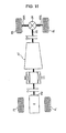
- Fig. 1 is a system diagram illustrating a rear-wheel-drive hybrid vehicle including the braking-force-distribution control apparatus according to a first embodiment of the invention.
- the drive system of the hybrid vehicle in this first embodiment includes an engine E, a flywheel FW, a first clutch CL1, a motor-generator MG, a second clutch CL2, an automatic transmission AT, a propeller shaft PS, a differential DF, a left drive shaft DSL, a right drive shaft DSR, a left rear wheel RL (driving wheel) and a right rear wheel RR (driving wheel).
- the vehicle has a left front wheel FL and a right front wheel FR.
- the wheels are provided with a left-rear-wheel brake unit BURL, a right-rear-wheel brake unit BURR, a left-front-wheel brake unit BUFL and a right-front-wheel brake unit BUFR.
- These brake units are frictional brake devices.
- the engine E can be, for example, a gasoline engine or a diesel engine, and a throttle valve position or the like is controlled on the basis of control commands output by an engine controller 1, which is described below.
- the flywheel FW is provided on an output shaft of the engine E.
- the first clutch CL1 is interposed between the engine E and the motor-generator MG.
- the first clutch CL1 is switched between an engaged state and a disengaged state including a slip-engaged state and a slip-disengaged state, respectively. This switching is responsive to an oil pressure generated by a first-clutch hydraulic unit 6 on the basis of a control command output by a first-clutch controller 5, which is described hereinafter.
- the motor-generator MG is a synchronous motor-generator including a rotor in which a permanent magnet is embedded and a stator around which a stator coil is wound.
- the motor-generator MG is controlled by applying a three-phase alternating current generated by an inverter 3a included in a power control unit 3 on the basis of a control command output by a motor controller 2, which is also described hereinafter.
- the motor-generator MG is capable of operating as an electric motor that rotates in response to electric power supplied from a hybrid battery 4 (i.e., an electric storage device). This operation is hereinafter called “power running”.
- the motor-generator MG is also capable of operating as a generator that generates an electromotive force at both ends of the stator coil to charge the hybrid battery 4 when the rotor is being rotated by an external force. This operation is hereinafter called "regeneration”.
- the rotor of the motor-generator MG is connected to an input shaft of the automatic transmission AT with a damper (not shown) provided therebetween.
- the power control unit 3 includes the following three components.
- the inverter 3a includes semiconductor switching elements (e.g., insulated gate bipolar transistors (IGBT)) for converting a direct current from the hybrid battery 4 into a three-phase alternating current for driving the motor-generator MG and a three-phase alternating current from the motor-generator MG into a direct current to be input to the hybrid battery 4.
- semiconductor switching elements e.g., insulated gate bipolar transistors (IGBT)
- a DC/DC converter 3c reduces a voltage from the hybrid battery 4 and supplies electric power to a battery 25.
- the battery 25 is a power supply for illumination, display, auxiliary devices, etc.
- a high-voltage circuit 3b is connected to the hybrid battery 4, the inverter 3a and the DC/DC converter 3c.
- the high-voltage circuit 3b contains a relay capable of shutting off the electric current to and from the high-voltage circuit 3b. As described below, when a collision of the vehicle occurs, the hybrid battery 4 and the motor-generator MG are shut off from each other by the relay included in the high-voltage circuit 3b.
- the second clutch CL2 is interposed between the motor-generator MG and the rear wheels RL and RR.
- the second clutch CL2 is switched between an engaged state and a disengaged state including a slip-engaged state and a slip-disengaged state, respectively.
- the switching occurs using an oil pressure generated by a second-clutch hydraulic unit 8 on the basis of a control command output by an AT controller 7, which is described hereinafter.
- the automatic transmission AT automatically switches a gear ratio among multiple gears, for example, five forward gears and one reverse gear, in accordance with a vehicle speed and a throttle position.
- the second clutch CL2 is not provided as a dedicated clutch but uses some of frictional fastening elements fastened at each shift position of the automatic transmission AT.
- An output shaft of the automatic transmission AT is connected respectively to the left and right rear wheels RL and RR with the propeller shaft PS and the differential DF, with left and right drive shafts DSL and DSR disposed therebetween.
- Each of the first clutch CL1 and the second clutch CL2 may be, for example, a multiple-disc wet clutch that can continuously control an oil flow rate and an oil pressure with a proportional solenoid.
- the hybrid drive system has two driving modes that are set in accordance with the engaged/disengaged state of the first clutch CL1.
- an electric drive mode hereinafter called an "EV mode”
- a motor drive mode is set in which only the power of the motor-generator MG is used as a power source for driving the vehicle.
- a hybrid drive mode hereinafter called an "HEV mode”
- the engine E is additionally used as a power source for driving the vehicle.
- the HEV mode includes an engine drive mode, a motor assist mode and a power-generating mode.
- the engine drive mode only the engine E is used as the power source for rotating the driving wheels RR and RL.
- the motor-assist mode the engine E and the motor-generator MG are both used as the power source for rotating the driving wheels RR and RL.
- the power-generating mode the engine E is used as the power source for rotating the driving wheels RR and RL, and the motor-generator MG is controlled to operate as a generator at the same time.
- the motor-generator MG When the vehicle runs at a constant speed or is accelerated, the motor-generator MG is controlled to operate as a generator using the power of the engine E. When the vehicle is decelerated, the motor-generator MG generates electric power by regenerating the braking energy, and thereby generates a regenerative braking force. The generated electric power is thus charged into the hybrid battery 4.
- a control system of the hybrid vehicle is next described.
- the control system of the hybrid vehicle includes an engine controller 1, the motor controller 2, the power control unit 3, the hybrid battery 4, the first-clutch controller 5, the first-clutch hydraulic unit 6, the AT controller 7, the second-clutch hydraulic unit 8, a brake controller 9 and an integrated controller 10.
- the engine controller 1, the motor controller 2, the first-clutch controller 5, the AT controller 7, the brake controller 9 and the integrated controller 10 are connected to each other via control area network (CAN) lines through which information can be communicated.
- CAN control area network
- Each controller generally consists of a microcomputer including central processing unit (CPU), input and output ports (I/O), random access memory (RAM), keep alive memory (KAM), a common data bus and read only memory (ROM) as an electronic storage medium for executable programs and certain stored values as discussed hereinafter.
- CPU central processing unit
- I/O input and output ports
- RAM random access memory
- KAM keep alive memory
- ROM read only memory
- the various parts of the integrated controller 10 described herein with respect to the figures could be, for example, implemented in software as the executable programs, or could be implemented in whole or in part by separate hardware in the form of one or more integrated circuits (IC).
- IC integrated circuits
- the engine controller 1 receives engine speed information from an engine speed sensor 12 and outputs a command for controlling an engine operating point (an engine speed Ne and an engine torque Te) to, for example, a throttle valve actuator (not shown) on the basis of a target engine torque command or the like from the integrated controller 10.
- the information of the engine speed Ne is supplied to the integrated controller 10 via the CAN lines 11.
- the motor controller 2 receives information from a resolver 13 for detecting a rotational position of the rotor included in the motor-generator MG. The motor controller 2 then outputs a command for controlling a motor operating point (a motor-generator speed Nm and a motor-generator torque Tm) based on a target motor-generator torque command and the like obtained from the integrated controller 10. In addition, the motor controller 2 monitors the state of charge (SOC) of the hybrid battery 4. The information regarding the SOC of the hybrid battery 4 is used for controlling the motor-generator MG and is supplied to the integrated controller 10 via the CAN lines 11.
- SOC state of charge
- the first-clutch controller 5 receives sensor information from a first-clutch oil-pressure sensor 14 and a first-clutch stroke sensor 15 and outputs a command for controlling the engaged/disengaged state of the first clutch CL1 to the first-clutch hydraulic unit 6 in accordance with a first-clutch control command from the integrated controller 10.
- the information regarding a first clutch stroke C1S is supplied to the integrated controller 10 via the CAN lines 11.
- the AT controller 7 receives sensor information from a throttle position sensor 16, a vehicle speed sensor 17 and a second-clutch oil-pressure sensor 18.
- the output of the AT controller 7 is a command for controlling the engaged/disengaged state of the second clutch CL2 sent to the second-clutch hydraulic unit 8 in an AT oil-pressure control valve in accordance with a second-clutch control command from the integrated controller 10.
- the information regarding a throttle position APO and a vehicle speed VSP is supplied to the integrated controller 10 via the CAN lines 11.
- the brake controller 9 receives sensor information from a wheel speed sensor 19 that detects a rotational speed of each of the four wheels and a brake stroke sensor 20 that detects a brake stroke BS.
- a required braking force is determined based on the brake stroke BS. If the required braking force cannot be provided only by the regenerative braking force generated by the motor-generator MG, a frictional braking force is generated to compensate for the deficiency. More specifically, the brake controller 9 controls the braking forces applied by the brake units BURL, BURR, BUFL and BUFR of the respective wheels on the basis of a regenerative cooperative brake control command from the integrated controller 10.
- the brake controller 9 operates as a so-called anti-skid braking system.
- the brake controller 9 detects brake locking based on the rotational speed of each of the four wheels, and controls the braking force so as to suppress the brake locking when a brake is applied on a low- ⁇ road or when a brake is suddenly applied.
- the integrated controller 10 has a function of managing the total energy consumption of the vehicle and driving the vehicle at a highest efficiency.
- the integrated controller 10 receives information from a motor speed sensor 21 that detects a motor speed Nm, a second-clutch output rotational speed sensor 22 that detects a second-clutch output rotational speed N2out, a second-clutch torque sensor 23 that detects a second-clutch torque TCL2 and a brake-oil-pressure sensor 24 and information obtained via the CAN lines 11.
- the integrated controller 10 also receives a collision impact signal from a collision impact sensor 26, such as an airbag sensor, which is described hereinafter.
- the integrated controller 10 controls the operation of the engine E by outputting the control command to the engine controller 1, the operation of the motor-generator MG by outputting the control command to the motor controller 2, the engaged/disengaged state of first clutch CL1 by outputting the control command to the first-clutch controller 5 and the engaged/disengaged state of the second clutch CL2 by outputting the control command to the AT controller 7.
- Collision impact sensor 26 is, for example, an airbag sensor that includes an acceleration sensor attached to the vehicle body. When a large acceleration is applied to the vehicle body, the airbag sensor outputs a collision impact signal that corresponds to the degree of acceleration to activate an airbag for protecting an occupant.
- a plurality of acceleration sensors may be provided for detecting accelerations in the front-rear direction, the right-left direction, etc., of the vehicle. In such a case, the direction of impact can be detected.
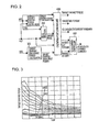
- a control operation executed by the integrated controller 10 according to the first embodiment is next described with reference to a block diagram shown in Fig. 2 .
- the operation described may be repeatedly executed with a control period of, for example, 10 msec.
- the integrated controller 10 includes a target-driving-force calculator 100, a mode selector 200, a target charge/discharge power calculator 300, an operating-point command unit 400 and a gear-change controller 500.
- the target-driving-force calculator 100 calculates a target driving force tFoO based on the throttle position APO and the vehicle speed VSP by referring to a target-driving-force map such as that shown in Fig. 3 .
- the mode selector 200 determines which of the EV mode and the HEV mode is to be set as a target mode based on the throttle position APO and the vehicle speed VSP by referring to an EV-HEV selection map such as that shown in Fig. 4 . However, if the SOC of the hybrid battery 4 is equal to or less than a predetermined value, the HEV mode is automatically selected as the target mode.
- the target charge/discharge power calculator 300 calculates a target charge/discharge power tP based on the SOC of the hybrid battery 4 by referring to a target charge/discharge power map such as that shown in Fig. 5 . As is clear from Fig. 5 , the hybrid battery 4 is discharged when the SOC thereof is high and is charged when the SOC thereof is low.
- the operating-point command unit 400 calculates a transient target engine torque, a target motor-generator torque, a target second-clutch torque capacity, a target shift position of the automatic transmission AT and a first-clutch solenoid current command as operating-point target values based on the throttle position APO, the target driving force tFoO, the target mode, the vehicle speed VSP and the target charge/discharge power tP.
- the gear-change controller 500 drives and controls a solenoid valve included in the automatic transmission AT so as to achieve the target second-clutch torque capacity and the target shift position.
- Fig. 6 is a flowchart of a process of calculating operating-point commands performed by the operating-point command unit 400 included in the integrated controller 10.
- step (hereinafter "S") 401 a transient target driving force tFo is obtained by performing a predetermined transient response process for the target driving force tFoO. Then, the process proceeds to S402.
- an output of a low-pass filter with a predetermined time constant obtained when the target driving force tFoO is input is the transient target driving force tFo.
- iG is a gear ratio at the current shift position. Then, the process proceeds to S403.
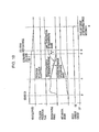
- the target shift position is calculated based on the throttle position APO and the vehicle speed VSP by referring to a shift map such as that shown in Fig. 7 .
- the solid line shows an up-shift line and the dashed line shows a down-shift line.
- the process advances to S404 wherein mode setting is performed in accordance with the target mode.
- the EV mode or the HEV mode is set as the target mode.
- mode-switch control for switching from the HEV mode to the EV mode is performed.
- mode-switch control for switching from the EV mode to the HEV mode is performed.
- the target engine torque tTe is determined by limiting the ideal engine torque tTeO with a maximum engine torque corresponding to the engine speed Ne by referring to a maximum-engine-torque map such as that shown in Fig. 8 .
- the target engine torque tTe is set to zero.
- the target motor-generator torque is determined by an operation performed during mode switching, which is described below.
- a target first-clutch torque capacity is set in S407 after the target motor-generator torque is calculated in S406.
- the target first-clutch torque capacity is set to zero if the EV mode is set and to a maximum value if the HEV mode is set. If the mode is being switched, the target first-clutch torque capacity is determined by the operation performed during mode switching described below.
- a target second-clutch torque capacity tcTcl2 is determined.
- the target second-clutch torque capacity tcTcl2 is set to a value evTmax that corresponds to a maximum driving force in the EV mode if the EV mode is set, and is set to a maximum value if the HEV mode is set. If the mode is being switched, the target second-clutch torque capacity tcTcl2 is determined by the operation performed during mode switching described below. The process ends upon completion of S408.
- Fig. 9 is a flowchart of an example braking-force-distribution control process performed by the integrated controller 10 for controlling a braking-force distribution in the event of a vehicle collision. This process is repeatedly executed with a control period of, for example, 10 msec.
- S101 it is determined whether or not a collision is detected based on a signal from the collision impact signal from an airbag sensor, which functions as a collision detector, or collision impact sensor, 26. If the response to this query is No, the process proceeds to S111. If the response is Yes, the process proceeds to S102.
- this braking-force-distribution control process the operation of controlling the braking-force distribution between the regenerative brake and the frictional brake is started when a collision of the vehicle is detected based on the signal from the airbag sensor.
- the collision detector 26 In place of the airbag sensor, other devices may also be used as the collision detector 26.
- One such alternative device for the collision detector 26 is a device that detects a collision of the vehicle using an acceleration sensor included in a vehicle motion control system or a traction control system.
- the vehicle motion control system is a system used for avoiding an obstacle while braking the vehicle by individually controlling a braking force applied to each wheel to generate a yaw moment.
- the traction control system is a system used for suppressing drive slip by controlling the driving/braking force when the drive slip occurs.
- the crash sensor may be a sensor that detects a collision based on a change in the longitudinal force applied to the vehicle or a sensor that detects a collision based on a change in an electrostatic capacitance.
- a power shut-off threshold is set.
- the power shut-off threshold which is a threshold for a collision impact value, is set by referring to a table showing the relationship between the collision direction and the power shut-off threshold. As described in detail below, the power shut-off threshold is used for determining, based on the collision impact value, whether or not it is necessary to change the braking-force distribution between the regenerative brake and the frictional brake and shut off the high-voltage circuit immediately when a collision occurs.
- the power shut-off threshold for the collision impact value is set to different values depending on the collision direction. More specifically, in the table showing the relationship between the collision direction and the power shut-off threshold, the power shut-off threshold for the collision impact value is set to a small value when the collision direction is a direction in which a high-voltage element, an electric storage element or an element using fuel is disposed.
- processing advances to S104, where the power shut-off threshold is set to a minimum value in consideration of the possibility that the collision direction may be the direction in which the high-voltage element, the electric storage element or the element using fuel is disposed.
- the process proceeds to S105.
- S105 it is determined whether or not the collision impact value is higher than the power shut-off threshold. If the result of this query is Yes, the process proceeds to S107. Otherwise, the process proceeds to S106.
- the braking-force distribution between the regenerative brake and the frictional brake is determined on the basis of the level of impact.
- S106 After it is determined that the collision impact value is equal to or lower than the power shut-off threshold in S105, in S106 it is determined whether or not the vehicle speed is equal to zero. If the vehicle speed is equal to zero, the process proceeds to S107. If the vehicle speed is not equal to zero, the process proceeds to S108.
- the process proceeds to S107 if the collision impact value is higher than the power shut-off threshold in S105 or if the collision impact value is equal to or lower than the power shut-off threshold but the vehicle speed is zero in response to the queries of S105 and S106.
- the braking-force distribution between the regenerative brake and the frictional brake is immediately changed. Then, the process proceeds to S110.
- the braking-force distribution between the regenerative brake and the frictional brake is changed immediately if it is determined that the collision impact value is higher than the power shut-off threshold.
- the braking-force distribution between the regenerative brake and the frictional brake is also changed immediately if the collision impact value is equal to or lower than the power shut-off threshold but the vehicle is stopped. In contrast, after it is determined that the vehicle speed is more than zero in S106, the braking-force distribution is changed at a rate within a change-rate limit in S108. Then, the process proceeds to S109.
- the braking-force-distribution control process if the collision impact value is lower than the power shut-off threshold, the braking-force distribution between the regenerative brake and the frictional brake is changed at such a rate that the vehicle's motion does not suddenly change.
- the high-voltage relay provided in the high-voltage circuit 3b is shut off in S110 and processing ends.
- S111 after no collision is detected in S101, it is determined whether or not a collision is predicted based on whether or not the anti-skid braking system, which functions as a collision predictor, is activated. If a collision is not predicted in S111, the process ends. If a collision is predicted in S111, the process proceeds to S112.
- an operation of controlling the braking-force distribution between the regenerative brake and the frictional brake can also be started when the anti-skid braking system (collision predictor) is activated, and a collision of the vehicle is predicted accordingly.
- the anti-skid braking system collision predictor
- other devices may also be used as the collision predictor.
- a device that predicts a collision of the vehicle when an intelligent brake assist is activated may also be used as the collision predictor.
- the intelligent brake assist includes a sensor for detecting a distance to a vehicle running in front and issues a warning for prompting the driver to perform an emergency operation. If the collision cannot be avoided by the emergency operation, the system automatically applies a brake.
- the intelligent brake assist is activated, a time to collision with the vehicle in front can be estimated.
- Another alternative device is a device that predicts a collision of the vehicle when it is determined that an obstacle is approaching the vehicle by a driving-environment monitor that monitors a driving environment of the vehicle.
- the driving-environment monitor may be, for example, a laser radar or a camera.
- a time to collision with the obstacle can also be estimated.
- S112 after a collision is predicted in S111, it is determined whether or not the time to collision can be estimated. If the time to collision can be estimated, the process proceeds to S113. If the response to the query of S112 is No, that is, the time to collision cannot be estimated, the process proceeds to S114. In the case in which only the anti-skid braking system is provided as the collision predictor, the result of the query is No in S112.
- a method for changing the braking-force distribution between the regenerative brake and the frictional brake is determined on the basis of the level of impact.
- a change rate of the braking-force distribution is determined based on the time to collision in S113 after it is decided that the time to collision can be estimated in S112.
- the change rate of the braking-force distribution is determined based on the estimated time to collision.
- the change rate of the braking-force distribution is determined based on the estimated time to collision with the obstacle.
- the change rate of the braking-force distribution is determined from a limitation based on the vehicle's motion in S114, after it is decided that the time to collision cannot be estimated in S112.
- the braking-force distribution between the regenerative brake and the frictional brake is changed in response to an activation of the anti-skid braking system, the braking-force distribution between the regenerative brake and the frictional brake is changed at such a rate that the vehicle's motion does not suddenly change.
- Step 115 the braking-force distribution is changed at the determined change rate such that the braking force of the regenerative brake is reduced and that of the frictional brake is increased. Then the process ends.
- the braking force of the regenerative brake applied by the motor-generator MG is reduced by limiting a proportion of the braking force of the regenerative brake applied by the motor-generator MG in a total braking force.
- the remaining proportion is allocated to the friction brake(s), so that the braking force of the frictional brake(s) is increased.
- the proportion of the braking force of the regenerative brake applied by the motor-generator MG in the total braking force is changed by one of the following methods.
- First is a method of reducing the proportion of the braking force of the regenerative brake applied by the motor-generator MG in the total braking force stepwise.
- Another possible method is a method of reducing the proportion of the braking force of the regenerative brake applied by the motor-generator MG in the total braking force in a ramp manner.
- a hybrid vehicle an electric vehicle (EV), a fuel-cell vehicle (FCV), etc.
- a hybrid vehicle include at least one electric storage device and at least one motor-generator for driving and braking.
- regenerative cooperative brake control is performed in which a braking force of a frictional brake is reduced or eliminated, while a braking force of a regenerative brake applied by the motor-generator is increased by an amount corresponding to the reduction in the braking force of the friction brake.
- a circuit through which a high-voltage current flows (high-voltage circuit) is shut off by a relay circuit.
- the proportion of the braking force of the regenerative brake in the required braking force is increased to a maximum and the remaining proportion is allocated to the frictional brake to reduce fuel consumption.
- the braking-force-distribution control apparatus and method taught herein can prevent the increase in the braking distance and the sudden change in the torque generated by the motor-generator and can shut off the high-voltage circuit using a relay that does not break due to seizing when the vehicle collides.
- the braking-force-distribution control apparatus performs the braking-force-distribution control process in which the braking force of the regenerative brake applied by the motor-generator MG is reduced and braking force of the frictional brake is increased when the vehicle collides.
- the high-voltage circuit can be shut off by a relay that does not break due to seizing.
- a braking-force-distribution control operation performed when only the collision detection can be performed, a braking-force-distribution control operation performed when both the collision detection and prediction can be performed, and effects of the braking-force-distribution control operation according to the first embodiment are described below.
- a braking-force-distribution control operation performed when only the collision detection can be performed is first described.
- the process proceeds to S101, S102, S103 (or S104), S105, S107 and S110, in that order, and then ends. More specifically, if the collision impact value is higher than the power shut-off threshold set in S103 or S104, the process proceeds to S107, where the braking-force distribution is immediately changed such that the braking force of the regenerative brake is reduced and that of the frictional brake is increased without taking a change-rate limit into account. Then, in S110, the high-voltage relay of the high-voltage circuit 3b is shut off.
- the process proceeds to S101, S102, S103 (or S104), S105, S106, S108 and S109, in that order, and then ends. These steps are repeated until it is determined that the operation of changing the braking-force distribution is finished in S109. Then, the process proceeds to S110 from S109, and then ends.
- the process proceeds to S108, where the braking-force distribution is changed such that braking force of the regenerative brake is reduced and that of the frictional brake is increased at a rate within the change-rate limit. Then, if it is determined that the operation of changing the braking-force distribution is finished in S109, the process proceeds to S110, where the high-voltage relay of the high-voltage circuit 3b is shut off.
- the process proceeds to S101, S102, S103 (or S104), S105, S106, S107 and S110, in that order, and then ends. More specifically, if the collision impact value is equal to or lower than the power shut-off threshold set in S103 or S104, and the vehicle speed is zero, the process proceeds to S107, where the braking-force distribution is immediately changed such that the braking force of the regenerative brake is reduced and that of the frictional brake is increased without taking a change-rate limit into account. Then, in S110, the high-voltage relay of the high-voltage circuit 3b is shut off.
- a braking-force-distribution control operation performed when both the collision detection and prediction can be performed is described.
- the process proceeds to S101, S111, S112, S113 (or S114) and S115, in that order, and then ends. More specifically, if a time to collision can be estimated in S112, the process proceeds to S113, where the change rate of the braking-force distribution is determined based on the time to collision. Then, the process proceeds to S115, where the braking-force distribution is changed at the determined change rate.
- the process proceeds to S114, where the change rate of the braking-force distribution is determined from a limitation based on the vehicle's motion. Then, the process proceeds to S115, where the braking-force distribution is changed at the determined change rate.
- S101 to S110 are executed as described above.
- the process waits until it is determined that the operation of changing the braking-force distribution is finished in S109, and then proceeds to S110.
- the high-voltage relay of the high-voltage circuit 3b is shut off.
- the process proceeds to S107 and then to S110, where the high-voltage relay of the high-voltage circuit 3b is shut off.
- Fig. 10 is a time chart showing the characteristics of the vehicle speed, the collision prediction flag, the regenerative brake, the mechanical brake and the high-voltage circuit.
- the time chart of Fig. 10 illustrates an example of a collision pattern obtained by a hybrid vehicle including a braking-force-distribution control apparatus as taught herein when the time to collision can be estimated and the operation of changing the braking-force distribution is finished before collision. Effects of the braking-force-distribution control operation are described below with reference to the time chart shown in Fig. 10 .
- the regenerative braking force is increased with quick response, and the mechanical brake (i.e., the friction brake(s)) is gradually increased after a short period from time t0.
- Time t2 is obtained by subtracting a set time t from the estimated time to collision. Accordingly, in the time period between time t1 at which the collision is predicted and time t2, the braking force of the regenerative brake is gradually reduced at the determined rate of reduction and the braking force of the mechanical brake is increased by an amount corresponding to the amount of reduction in the braking force of the regenerative brake.
- the high-voltage relay of the high-voltage circuit 3b is shut off at time t4 at which time the vehicle speed is reduced to zero.
- a braking-force-distribution control apparatus and method for controlling a braking-force distribution in a vehicle collision are used in a vehicle including at least one electric storage device and at least one motor-generator MG for driving and braking.
- regenerative cooperative brake control is performed in which a braking force of a frictional brake is reduced or eliminated while a braking force of a regenerative brake applied by the motor-generator MG is increased by an amount corresponding to the reduction in the braking force of the friction brake.
- the braking-force-distribution control apparatus reduces the braking force of the regenerative brake applied by the motor-generator MG and increases the braking force of the friction brake. Therefore, when the vehicle collides, an increase in the braking distance and a sudden change in the torque generated by the motor-generator MG can be prevented. Also, the high-voltage circuit 3b can be shut off with a relay that does not break due to seizing.
- the braking-force-distribution control apparatus and method start to control the braking-force distribution between the regenerative brake and the frictional brake when the collision detector detects a collision of the vehicle (see, e.g., S101). Therefore, when a vehicle collision is detected, an increase in the braking distance and a sudden change in the torque generated by the motor-generator MG can be prevented, and the high-voltage circuit 3b can be shut off with a relay that does not break due to seizing.
- the collision detector detects a collision of the vehicle (see, e.g., S101) with an airbag sensor, for example, and accordingly the operation of controlling the braking-force distribution between the regenerative brake and the frictional brake is started. Since the airbag sensor that is initially mounted in the vehicle is used, in addition to the advantages mentioned as the second point above, the collision detector can be provided without increasing the cost.
- the collision detector detects a collision of the vehicle (see, e.g., S101) with an acceleration sensor included in a vehicle motion control system or a traction control system, for example, and accordingly the operation of controlling the braking-force distribution between the regenerative brake and the frictional brake is started. Since the acceleration sensor that is initially mounted in the vehicle is used, in addition to the advantages mentioned as to the second point above, the collision detector can be provided without increasing the cost.
- the collision detector detects a collision of the vehicle (see, e.g., S101) with a crash sensor, for example, and accordingly the operation of controlling the braking-force distribution between the regenerative brake and the frictional brake is started. Therefore, in addition to the advantages mentioned in the second point above, conditions under which the braking-force distribution is changed can be set in accordance with the sensitivity and orientation of the crash sensor.
- the braking-force-distribution control apparatus and method determine the braking-force distribution between the regenerative brake and the frictional brake based on the level of impact when a collision of the vehicle is detected. If the level of impact of the collision is high, and the vehicle is severely damaged, the braking-force distribution is quickly changed. The high-voltage circuit 3b is quickly shut off to prevent vehicle fire and electrification. If the level of impact of the collision is low, and the vehicle is not severely damaged, the braking-force distribution is changed at such a rate that the vehicle's motion does not suddenly change. Accordingly, a shock in the driving/braking force does not occur and the vehicle's motion can be prevented from becoming unstable.
- the braking-force-distribution control apparatus and method immediately change the braking-force distribution between the regenerative brake and the frictional brake (see, e.g., S107) if the collision impact value is higher than the power shut-off threshold. Accordingly, the state in which the high-voltage circuit 3b can be shut off is quickly established. In addition, even when the high-voltage circuit 3b is shut off immediately after the collision, the vehicle can be stopped by the friction brake(s).
- the braking-force-distribution control apparatus and method change the braking-force distribution between the regenerative brake and the frictional brake at such a rate that the vehicle's motion does not suddenly change (see e.g., S108) if the collision impact value is equal to or lower than the power shut-off threshold. Therefore, a shock in the driving/braking force due to a sudden change in the motor torque does not occur, and the vehicle's motion can be prevented from becoming unstable.
- the braking-force-distribution control apparatus and method immediately change the braking-force distribution between the regenerative brake and the frictional brake (S106 ⁇ S107).
- the vehicle's motion does not become unstable even if the braking-force distribution is suddenly changed. Therefore, in such a case, the state in which the high-voltage circuit 3b can be shut off is quickly established by immediately changing the braking-force distribution.
- the state in which the high-voltage circuit 3b can be shut off is quickly established, so that the high-voltage circuit 3b can be quickly shut off to prevent electrification. Therefore, the advantages mentioned in the seventh and eighth items above can be obtained.
- the braking-force-distribution control apparatus and method set the power shut-off threshold for the collision impact value to different values depending on a collision direction (see, e.g., S103). Therefore, the advantages mentioned in the seventh through ninth items above can be optimally and safely obtained.
- the braking-force-distribution control apparatus and method set the power shut-off threshold for the collision impact value to a small value when the collision direction is a direction in which a high-voltage element, an electric storage element or an element using fuel is disposed (see, e.g., S103). Accordingly, the braking-force distribution is suddenly changed when an impact is applied in the direction in which the high-voltage element, the electric storage element or the element using fuel is disposed. In other cases, the brake performance is prioritized in the operation of controlling the braking-force distribution. Therefore, the advantages mentioned in the seventh through ninth items above can be optimally and safely obtained.
- the braking-force-distribution control apparatus and method start the operation of controlling the braking-force distribution between the regenerative brake and the frictional brake when a collision of the vehicle is predicted by the collision predictor (see, e.g., S111). Therefore, when a collision is predicted, the braking-force distribution can be controlled before the vehicle actually collides so that an increase in the braking distance and a sudden change in the torque generated by the motor-generator MG can be prevented. Also, the high-voltage circuit 3b can be shut off with a relay that does not break due to seizing.
- the collision predictor predicts a collision of the vehicle (see, e.g., S111) when an intelligent brake assist is activated. Accordingly, the operation of controlling the braking-force distribution between the regenerative brake and the frictional brake is started. Since the information from the intelligent brake assist system that is initially mounted in the vehicle is used, in addition to the advantages mentioned in the twelfth item above, the collision predictor can be provided without increasing the cost.
- the collision predictor predicts a collision of the vehicle (see, e.g., S111) when an anti-skid braking system is activated. Accordingly, the operation of controlling the braking-force distribution between the regenerative brake and the frictional brake is started. Since the information from the anti-skid braking system that is initially mounted in the vehicle is used, in addition to the advantages mentioned in the twelfth item above, the collision predictor can be provided without increasing the cost.
- the collision predictor predicts a collision of the vehicle (see, e.g., S111) when a driving-environment monitor that monitors a driving environment of the vehicle determines that an obstacle is approaching the vehicle. Accordingly, the operation of controlling the braking-force distribution between the regenerative brake and the frictional brake is started. Therefore, in addition to the advantages described in the twelfth item above, conditions under which the braking-force distribution is changed can be set in accordance with the sensor and method of detecting the possibility of collision.
- the braking-force-distribution control apparatus and method determine the braking-force distribution between the regenerative brake and the frictional brake based on an estimated state of collision.
- the vehicle's motion is prioritized, and the braking-force distribution is relatively slowly changed. Accordingly, the braking-force distribution can be safely changed.
- the braking-force distribution is changed such that the operation of changing the braking-force distribution can be finished before the collision. Accordingly, the operation of changing the braking-force distribution can be finished before the collision.
- the change rate of the braking-force distribution is determined on the basis of the estimated time to collision (S112 ⁇ S113). Since the time to collision with the vehicle in front can be estimated, the operation of changing the braking-force distribution can be finished by the time the vehicle collides with the vehicle in front.
- the braking-force-distribution control apparatus and method start to change the braking-force distribution between the regenerative brake and the frictional brake in response to an activation of the anti-skid braking system
- the braking-force distribution between the regenerative brake and the frictional brake is changed at a rate within such a range that the vehicle's motion does not suddenly change (S112 ⁇ S114). Therefore, although the time to collision cannot be estimated, the operation of changing the braking-force distribution can be started without suddenly changing the vehicle's motion.
- the change rate of the braking-force distribution between the regenerative brake and the frictional brake is determined based on the estimated time to collision with the obstacle (S112 ⁇ S113). Since the time to collision with the obstacle can be estimated, the operation of changing the braking-force distribution can be finished by the time the vehicle collides with the obstacle.
- the braking-force-distribution control apparatus and method change the braking-force distribution by limiting a proportion of the braking force of the regenerative brake applied by the motor-generator MG in a total braking force and that of the braking force of the friction brake. Therefore, the change rate of the braking-force distribution between the regenerative brake and the frictional brake can be controlled by adjusting the manner in which the proportions of the braking forces of regenerative brake and the frictional brake in the total braking force are changed.
- the braking-force-distribution control apparatus and method change the braking-force distribution by limiting a proportion of the braking force of the regenerative brake applied by the motor-generator MG in a total braking force and allocating the remaining proportion to the friction brake. Accordingly, the change rate of the braking-force distribution between the regenerative brake and the frictional brake can be controlled based on the manner in which the proportion of the braking force of the regenerative brake in the total braking force is limited.
- the braking-force-distribution control apparatus and method change the braking-force distribution by reducing the proportion of the braking force of the regenerative brake applied by the motor-generator MG in the total braking force stepwise. Accordingly, the braking-force distribution can be prevented from being suddenly changed.
- the braking-force-distribution control apparatus and method change the braking-force distribution by reducing the proportion of the braking force of the regenerative brake applied by the motor-generator MG in the total braking force in a ramp manner. Accordingly, the braking-force distribution can be prevented from being suddenly changed.
- the braking-force-distribution control apparatus and method limit the change rate of the braking-force distribution based on response speeds of the regenerative brake applied by the motor-generator MG and the friction brake. Therefore, when the braking-force distribution between the regenerative brake and the frictional brake is changed, the total braking force can be prevented from being varied due to response delay.
- the braking-force-distribution control apparatus and method limit the change rate of the braking-force distribution such that the operation of changing the braking-force distribution is finished within a desired time. Accordingly, the braking-force distribution between the regenerative brake and the frictional brake can be finished within the desired time. In addition, the braking-force distribution can be prevented from being changed at an unnecessarily high change rate, and accordingly the vehicle's motion can be prevented from being suddenly changed.
- the braking-force-distribution control apparatus and method change the braking-force distribution between the regenerative brake applied by the motor-generator MG and the frictional brake to a distribution such that no malfunction occurs even if the high-voltage relay of the motor-generator MG is shut off. Therefore, malfunction can be prevented when the high-voltage relay is shut off after the braking-force distribution between the regenerative brake and the frictional brake is changed.
- the above-described vehicle is a hybrid vehicle that has a hybrid driving system including the first clutch CL1 interposed between the engine E and the motor-generator MG and the second clutch CL2 interposed between the motor-generator MG and the driving wheels RR and RL.
- the braking-force-distribution control apparatus and method disengage the second clutch CL2. Accordingly, even when the high-voltage relay is shut off, the vehicle's motion is prevented from being influenced by a sudden change in the motor torque, and a torque change that occurs when the second clutch CL2 is disengaged can be reduced.
- the braking-force-distribution control apparatus and method start the reengagement of the second clutch CL2 from the state in which the clutch input shaft and the clutch output shaft are not directly connected to each other. Therefore, the shock in the driving force can be reduced at the time of reengagement.
- the braking-force-distribution control apparatus and method control the high-voltage circuit 3b in accordance with the state of the vehicle. Therefore, the high-voltage circuit 3b can be reliably shut off when there is a possibility of short circuit. When there is no possibility of short circuit, the high-voltage circuit is not shut off, and the operation of the vehicle system is prioritized.
- the braking-force-distribution control apparatus and method shut off the high-voltage circuit 3b after the operation of changing the braking-force distribution between the regenerative brake applied by the motor-generator MG and the frictional brake is finished. Therefore, the vehicle's motion is prevented from being suddenly changed when the high-voltage circuit 3b is shut off.
- the braking-force-distribution control apparatus and method continuously operate the DC/DC converter 3c until the voltage of the inverter 3a of the motor-generator MG is reduced. Therefore, safety can be ensured after the high-voltage circuit 3b is shut off.
- the braking-force-distribution control apparatus and method allow power running of the motor-generator MG if the second clutch CL2 is disengaged. Therefore, the remaining voltage of the motor-generator MG and the inverter 3a can be consumed. In addition, since power running of the motor-generator MG is performed after the second clutch CL2 is disengaged, the generated torque is prevented from affecting the driving force.
- the braking-force-distribution control apparatus and method allow power running of the motor-generator MG and increase the braking force of the frictional brake by the amount corresponding to the power-running torque. Therefore, the remaining voltage of the motor-generator MG and the inverter 3a can be consumed, and the power running torque generated by the motor-generator MG can be canceled by the friction brake.
- the invention is applied to a rear-wheel-drive hybrid vehicle according to the described embodiments, the invention may also be applied to front-wheel-drive hybrid vehicles and four-wheel-drive hybrid vehicles.
- a clutch mounted in the automatic transmission is explained as the second clutch, a clutch that is additionally provided between a motor-generator and a transmission may be used as the second clutch.
- a second clutch CL2 may also be additionally provided between the transmission AT and driving wheels RR, RL.
- a belt-type or toroidal-type non-stage transmission may also be used in place of the automatic transmission AT.
- the invention may also be applied to an electric vehicle or a fuel-cell vehicle.
- the invention may be applied to any type of vehicle that includes at least one electric storage device and at least one motor-generator for driving and braking and that performs regenerative cooperative brake control when the vehicle decelerates or stops in response to a brake operation.
- the braking force of the frictional brake is reduced or eliminated while the braking force of the regenerative brake applied by the motor-generator is increased by an amount corresponding to the reduction in the braking force of the frictional brake in the regenerative cooperative brake control.
Landscapes
- Engineering & Computer Science (AREA)
- Transportation (AREA)
- Mechanical Engineering (AREA)
- Power Engineering (AREA)
- Sustainable Development (AREA)
- Sustainable Energy (AREA)
- Life Sciences & Earth Sciences (AREA)
- Chemical & Material Sciences (AREA)
- Combustion & Propulsion (AREA)
- Automation & Control Theory (AREA)
- Physics & Mathematics (AREA)
- Electromagnetism (AREA)
- Electric Propulsion And Braking For Vehicles (AREA)
- Regulating Braking Force (AREA)
- Traffic Control Systems (AREA)
- Hybrid Electric Vehicles (AREA)
- Hydraulic Clutches, Magnetic Clutches, Fluid Clutches, And Fluid Joints (AREA)
Applications Claiming Priority (3)
| Application Number | Priority Date | Filing Date | Title |
|---|---|---|---|
| JP2006090027 | 2006-03-29 | ||
| JP2007002282A JP4743121B2 (ja) | 2006-03-29 | 2007-01-10 | 車両の衝突時ブレーキ配分制御装置 |
| EP07104965A EP1839985B1 (de) | 2006-03-29 | 2007-03-27 | Fahrzeugbremse |
Related Parent Applications (1)
| Application Number | Title | Priority Date | Filing Date |
|---|---|---|---|
| EP07104965.4 Division | 2007-03-27 |
Publications (2)
| Publication Number | Publication Date |
|---|---|
| EP2330007A1 true EP2330007A1 (de) | 2011-06-08 |
| EP2330007B1 EP2330007B1 (de) | 2013-10-16 |
Family
ID=38191380
Family Applications (2)
| Application Number | Title | Priority Date | Filing Date |
|---|---|---|---|
| EP07104965A Ceased EP1839985B1 (de) | 2006-03-29 | 2007-03-27 | Fahrzeugbremse |
| EP11001471.9A Not-in-force EP2330007B1 (de) | 2006-03-29 | 2007-03-27 | Fahrzeugbremse |
Family Applications Before (1)
| Application Number | Title | Priority Date | Filing Date |
|---|---|---|---|
| EP07104965A Ceased EP1839985B1 (de) | 2006-03-29 | 2007-03-27 | Fahrzeugbremse |
Country Status (3)
| Country | Link |
|---|---|
| US (1) | US8016367B2 (de) |
| EP (2) | EP1839985B1 (de) |
| JP (1) | JP4743121B2 (de) |
Cited By (5)
| Publication number | Priority date | Publication date | Assignee | Title |
|---|---|---|---|---|
| CN107000607A (zh) * | 2014-12-08 | 2017-08-01 | 日产自动车株式会社 | 制动力驱动力控制装置以及制动力驱动力控制方法 |
| CN108349487A (zh) * | 2015-11-20 | 2018-07-31 | 五十铃自动车株式会社 | 混合动力车辆及其控制方法 |
| CN109532817A (zh) * | 2019-01-04 | 2019-03-29 | 大连民族大学 | 混合动力电动汽车基于soc的再生制动力矩分配方法 |
| CN112937531A (zh) * | 2021-03-30 | 2021-06-11 | 柳工柳州传动件有限公司 | 一种工程机械的行车制动系统及制动方法 |
| EP4414202A3 (de) * | 2023-02-07 | 2024-10-09 | Hyster-Yale Materials Handling, Inc. | Brennstoffzelle und h2-speicher-schlagschutzsystem für fahrzeuge |
Families Citing this family (74)
| Publication number | Priority date | Publication date | Assignee | Title |
|---|---|---|---|---|
| JP5590204B2 (ja) * | 2008-03-03 | 2014-09-17 | 日産自動車株式会社 | 車両のトラクション制御装置 |
| JP5291989B2 (ja) * | 2008-05-29 | 2013-09-18 | 本田技研工業株式会社 | 車両走行制御装置及びその方法 |
| US8670909B2 (en) * | 2009-07-14 | 2014-03-11 | Ford Global Technologies, Llc | Automotive vehicle |
| KR101304208B1 (ko) * | 2009-09-01 | 2013-09-05 | 주식회사 만도 | 회생 제동 시스템의 유압 제어 방법 |
| WO2011027441A1 (ja) * | 2009-09-03 | 2011-03-10 | ボッシュ株式会社 | 車両制動力制御装置 |
| DE102010029299B4 (de) | 2010-05-26 | 2023-06-29 | Robert Bosch Gmbh | Verfahren zum Betreiben eines Systems, System, Steuerung und Computergrogrammprodukt |
| US8433491B2 (en) * | 2010-10-12 | 2013-04-30 | Toyota Motor Engineering & Manufacturing North America, Inc. | Electromechanical deceleration system and method for operating the same |
| DE102010052964A1 (de) * | 2010-11-30 | 2012-05-31 | Valeo Schalter Und Sensoren Gmbh | Verfahren zum Betreiben eines Fahrzeugs und Fahrerassistenzeinrichtung |
| DE102011010230B4 (de) * | 2011-02-03 | 2021-05-20 | Audi Ag | Verfahren und Vorrichtung zur Steuerung der Stromversorgung in einem Stromnetz eines Kraftwagens, sowie Kraftwagen |
| DE102011006510A1 (de) * | 2011-03-31 | 2012-10-04 | Robert Bosch Gmbh | Verfahren zum Betreiben eines Kraftfahrzeugs, insbesondere Hybridfahrzeugs |
| US9493148B2 (en) | 2011-04-13 | 2016-11-15 | Ford Global Technologies, Llc | Torque modulation in a hybrid vehicle downshift during regenerative braking |
| EP2708430B1 (de) | 2011-05-12 | 2019-06-26 | Toyota Jidosha Kabushiki Kaisha | Fahrzeug |
| DE102011103936B4 (de) * | 2011-06-10 | 2016-02-11 | Audi Ag | Verfahren und Vorrichtung zum Abbremsen eines Kraftfahrzeugs |
| JP5408193B2 (ja) * | 2011-06-23 | 2014-02-05 | トヨタ自動車株式会社 | 車両の異常検出装置 |
| JP5397432B2 (ja) * | 2011-08-22 | 2014-01-22 | トヨタ自動車株式会社 | 回転電機の駆動システム |
| US8855844B2 (en) * | 2011-10-11 | 2014-10-07 | Robert Bosch Gmbh | System and method for optimal deceleration of a vehicle using regenerative braking |
| FR2983436B1 (fr) * | 2011-12-05 | 2013-11-22 | Renault Sa | Estimation d'energie recuperee |
| JP5786960B2 (ja) * | 2011-12-24 | 2015-09-30 | トヨタ自動車株式会社 | 車両の制御装置 |
| JP5910858B2 (ja) * | 2012-01-16 | 2016-04-27 | 日立工機株式会社 | チェンソー |
| JP5915208B2 (ja) * | 2012-01-31 | 2016-05-11 | 日産自動車株式会社 | 電動車両の回生ブレーキ制御装置 |
| JP5804186B2 (ja) * | 2012-03-07 | 2015-11-04 | 日産自動車株式会社 | 制動制御装置 |
| US8932179B2 (en) | 2012-05-04 | 2015-01-13 | Ford Global Technologies, Llc | Methods and systems for transitioning between braking modes |
| US8649952B2 (en) * | 2012-06-13 | 2014-02-11 | Ford Global Technologies, Llc | Control of a backing vehicle |
| JP6299096B2 (ja) * | 2012-09-27 | 2018-03-28 | 中西金属工業株式会社 | キャパシタ及び二次電池を電源とした自走式搬送システム |
| JP6079278B2 (ja) * | 2013-02-05 | 2017-02-15 | 富士電機株式会社 | 車両の走行モータ制御システム |
| JP6311225B2 (ja) * | 2013-06-17 | 2018-04-18 | 日産自動車株式会社 | 車両用高電圧遮断装置 |
| GB2516257B (en) | 2013-07-16 | 2019-06-19 | Bentley Motors Ltd | Brake control with obstacle detection to optimise regenerative braking |
| US9187081B2 (en) | 2013-09-25 | 2015-11-17 | Ford Global Technologies, Llc | Regenerative braking and torque converter control |
| JP6011508B2 (ja) * | 2013-10-16 | 2016-10-19 | トヨタ自動車株式会社 | 車両 |
| KR101480649B1 (ko) * | 2013-11-26 | 2015-01-09 | 현대자동차주식회사 | 차량 제어시스템 및 그 운용방법 |
| JP6233063B2 (ja) | 2014-01-31 | 2017-11-22 | トヨタ自動車株式会社 | 車両 |
| JP6254879B2 (ja) * | 2014-03-25 | 2017-12-27 | 株式会社Subaru | 車両用制御装置 |
| US9493075B2 (en) | 2014-03-25 | 2016-11-15 | Ford Global Technologies, Llc | Regenerative braking control system and method |
| FR3019111B1 (fr) * | 2014-03-31 | 2017-12-08 | Peugeot Citroen Automobiles Sa | Procede de securisation d'un vehicule hybride en cas d’accident, pour vider les condensateurs de puissance |
| JP6204865B2 (ja) * | 2014-03-31 | 2017-09-27 | 日立オートモティブシステムズ株式会社 | 車両の運動制御システム、車両、および、プログラム |
| JP5949826B2 (ja) * | 2014-04-11 | 2016-07-13 | 株式会社デンソー | 車両制御装置 |
| JP6378958B2 (ja) * | 2014-07-17 | 2018-08-22 | 日立建機株式会社 | 鉱山用ダンプトラック |
| JP6493656B2 (ja) * | 2014-08-22 | 2019-04-03 | 三菱自動車工業株式会社 | 車両の制動装置 |
| KR101628148B1 (ko) * | 2014-08-27 | 2016-06-08 | 현대자동차 주식회사 | 하이브리드 차량의 회생 제동 장치 및 방법 |
| US20160144721A1 (en) * | 2014-11-20 | 2016-05-26 | Ford Global Technologies, Llc | System and method for optimizing regenerative braking in adaptive cruise control |
| FR3035844B1 (fr) * | 2015-05-06 | 2018-08-03 | Psa Automobiles Sa. | Dispositif de commande de l’intensite du freinage pour un vehicule automobile |
| US9840865B2 (en) * | 2015-07-01 | 2017-12-12 | Hon Hai Precision Industry Co., Ltd. | Device, system and method for reducing physical impacts |
| JP6332181B2 (ja) * | 2015-07-16 | 2018-05-30 | トヨタ自動車株式会社 | 車両の制御装置 |
| US9969343B2 (en) * | 2015-07-24 | 2018-05-15 | Robert Bosch Gmbh | Methods and systems for managing an electrical connection between a power regulating device and an energy storage device included in a vehicle |
| MY190446A (en) * | 2015-08-26 | 2022-04-21 | Nissan Motor | Control method and control device for electric vehicle |
| US9499141B1 (en) | 2015-09-29 | 2016-11-22 | Faraday & Future Inc. | Sensor-triggering of friction and regenerative braking |
| JP2017105365A (ja) * | 2015-12-10 | 2017-06-15 | トヨタ自動車株式会社 | ハイブリッド車両の駆動力制御装置 |
| CN105799518B (zh) * | 2016-03-31 | 2019-02-15 | 北京长城华冠汽车科技股份有限公司 | 一种电动汽车的高压保护方法和装置 |
| CN105654752B (zh) * | 2016-04-06 | 2018-06-29 | 河南理工大学 | 一种用于多个车辆的汽车行驶安全预警装置 |
| CN109311462B (zh) * | 2016-06-15 | 2021-03-05 | 日立汽车系统株式会社 | 车辆控制装置 |
| JP6595417B2 (ja) * | 2016-08-10 | 2019-10-23 | 株式会社アドヴィックス | 車両用制動装置 |
| CN106877782A (zh) * | 2017-03-28 | 2017-06-20 | 联想(北京)有限公司 | 电机控制电路、装置和电机控制方法 |
| WO2018179359A1 (ja) * | 2017-03-31 | 2018-10-04 | 本田技研工業株式会社 | 車両制御システム、車両制御方法、および車両制御プログラム |
| DE102017214787A1 (de) * | 2017-08-23 | 2019-02-28 | Bayerische Motoren Werke Aktiengesellschaft | Impulsstart in einem Hybrid-Antriebsstrang |
| JP2019092267A (ja) * | 2017-11-13 | 2019-06-13 | トヨタ自動車株式会社 | 電動車両の制御装置 |
| KR102429505B1 (ko) * | 2017-12-28 | 2022-08-05 | 현대자동차주식회사 | 차량의 회생 제동 제어 장치 및 방법 |
| US11498561B1 (en) * | 2018-04-09 | 2022-11-15 | Apple Inc. | Vehicle deceleration system |
| EP3659851A1 (de) * | 2018-11-27 | 2020-06-03 | eMining AG | Steuereinheit zur steuerung einer bremsanlage, fahrzeug mit der steuereinheit und verfahren zum betrieb des fahrzeugs |
| DE102019204708A1 (de) | 2019-04-02 | 2020-10-08 | Volkswagen Aktiengesellschaft | Verfahren zum Verzögern eines Kraftfahrzeugs bei einer Notbremsung mit einem Elektromotor eines Elektroantriebs des Kraftfahrzeugs und einem Bremsmoment einer Betriebsbremsanlage des Kraftfahrzeugs, sowie Kraftfahrzeug |
| JP7214581B2 (ja) * | 2019-06-28 | 2023-01-30 | 株式会社クボタ | 作業機 |
| WO2020262427A1 (ja) | 2019-06-28 | 2020-12-30 | 株式会社クボタ | 作業機 |
| JP7438619B2 (ja) * | 2019-08-30 | 2024-02-27 | ダイハツ工業株式会社 | 回生制御装置 |
| JP7303736B2 (ja) * | 2019-12-12 | 2023-07-05 | 株式会社Subaru | 車両の制御装置 |
| US12194865B2 (en) * | 2020-02-11 | 2025-01-14 | Accelerated Systems Inc. | Methods and systems for controlling electric vehicles |
| US20210362719A1 (en) * | 2020-05-19 | 2021-11-25 | Waymo Llc | Arbitrating friction and regenerative braking for autonomous vehicles |
| CN111619366B (zh) * | 2020-05-28 | 2021-03-09 | 清华大学 | 基于电机旋变和轮速传感器的控制系统及控制方法 |
| JP6921287B1 (ja) * | 2020-09-04 | 2021-08-18 | ▲福衛▼ 澤田 | クラッチ装置及び衝突緩和機構 |
| US11572066B2 (en) | 2020-12-16 | 2023-02-07 | Cnh Industrial America Llc | Self-contained intelligent braking subsystem |
| US12122341B2 (en) | 2020-12-16 | 2024-10-22 | Cnh Industrial America Llc | Electronic braking system |
| CN113147753B (zh) * | 2021-03-24 | 2022-09-13 | 江铃汽车股份有限公司 | 车辆制动控制方法、装置、存储介质及自动制动系统 |
| CN115257387A (zh) * | 2022-08-31 | 2022-11-01 | 奇瑞汽车股份有限公司 | 一种基于碰撞预判断逻辑的高压卸载保护方法及装置 |
| FR3144796A1 (fr) * | 2023-01-11 | 2024-07-12 | Psa Automobiles Sa | Contrôle de chaque consigne de couple demandée pour un gmp d’un véhicule terrestre en présence d’un risque de collision |
| CN119099570A (zh) * | 2023-06-07 | 2024-12-10 | 比亚迪股份有限公司 | 车辆制动控制方法、控制器及车辆 |
| CN120517376B (zh) * | 2025-07-24 | 2025-10-10 | 长沙湘电电气技术有限公司 | 一种基于高速永磁同步电机的车辆制动控制系统 |
Citations (8)
| Publication number | Priority date | Publication date | Assignee | Title |
|---|---|---|---|---|
| JPH0759202A (ja) | 1993-08-12 | 1995-03-03 | Fuji Electric Co Ltd | 電気自動車の電気システム |
| JPH1066248A (ja) | 1996-08-20 | 1998-03-06 | Yazaki Corp | 車両用電源供給装置 |
| US6709075B1 (en) * | 2000-08-07 | 2004-03-23 | Ford Global Technologies, Llc | System and method for braking an electric drive vehicle on a low Mu surface |
| JP2005094883A (ja) | 2003-09-16 | 2005-04-07 | Nissan Motor Co Ltd | 車両用制御装置 |
| DE10346857A1 (de) * | 2003-10-09 | 2005-05-04 | Bosch Gmbh Robert | Vorrichtung zur Absicherung einer Starterleitung oder einer Starter- und Generatorleitung in einem Kraftfahrzeug |
| WO2006029353A2 (en) * | 2004-09-09 | 2006-03-16 | Kelsey-Hayes Company | Vehicular system having regenerative brake control |
| JP2006090027A (ja) | 2004-09-24 | 2006-04-06 | Matsushita Electric Works Ltd | フラッシュパネル |
| JP2007002282A (ja) | 2005-06-22 | 2007-01-11 | Mitsubishi Materials Corp | 縁部絶縁部材 |
Family Cites Families (15)
| Publication number | Priority date | Publication date | Assignee | Title |
|---|---|---|---|---|
| JPS6149601A (ja) * | 1984-08-17 | 1986-03-11 | Mitsubishi Electric Corp | 電気車用界磁チヨツパ制御装置 |
| JPH06153315A (ja) * | 1992-11-13 | 1994-05-31 | Honda Motor Co Ltd | 電動車両の制動装置 |
| US5615933A (en) * | 1995-05-31 | 1997-04-01 | General Motors Corporation | Electric vehicle with regenerative and anti-lock braking |
| US6364433B1 (en) * | 1999-05-07 | 2002-04-02 | Werner H. Stemer | Automotive brake system and method |
| US6520044B1 (en) * | 2000-06-01 | 2003-02-18 | Acutex, Inc. | Brake pedal shock absorber and method |
| US6370461B1 (en) * | 2000-06-27 | 2002-04-09 | Ford Global Technologies, Inc. | Crash control system for vehicles employing predictive pre-crash signals |
| JP2002316629A (ja) * | 2001-04-24 | 2002-10-29 | Toyota Motor Corp | 車両の衝突時制御装置 |
| JP3999982B2 (ja) | 2002-02-28 | 2007-10-31 | 三洋電機株式会社 | 誘導式車両 |
| JP2005113760A (ja) * | 2003-10-07 | 2005-04-28 | Nissan Motor Co Ltd | 衝突衝撃軽減装置および衝突衝撃軽減方法 |
| JP2005219536A (ja) * | 2004-02-03 | 2005-08-18 | Mitsubishi Motors Corp | 乗員保護装置 |
| JP2006014541A (ja) * | 2004-06-29 | 2006-01-12 | Toyota Motor Corp | 車両用モータ装置 |
| JP4760246B2 (ja) * | 2004-09-30 | 2011-08-31 | トヨタ自動車株式会社 | 液圧ブレーキ装置 |
| US7422293B2 (en) * | 2005-07-26 | 2008-09-09 | Ford Global Technologies, Llc | System and a method for dissipating voltage in an electrical circuit of a vehicle |
| JP3888383B2 (ja) * | 2005-08-26 | 2007-02-28 | マツダ株式会社 | 車両の制動装置 |
| JP4760277B2 (ja) * | 2005-10-04 | 2011-08-31 | トヨタ自動車株式会社 | 車両の制御装置 |
-
2007
- 2007-01-10 JP JP2007002282A patent/JP4743121B2/ja not_active Expired - Fee Related
- 2007-03-15 US US11/724,543 patent/US8016367B2/en active Active
- 2007-03-27 EP EP07104965A patent/EP1839985B1/de not_active Ceased
- 2007-03-27 EP EP11001471.9A patent/EP2330007B1/de not_active Not-in-force
Patent Citations (8)
| Publication number | Priority date | Publication date | Assignee | Title |
|---|---|---|---|---|
| JPH0759202A (ja) | 1993-08-12 | 1995-03-03 | Fuji Electric Co Ltd | 電気自動車の電気システム |
| JPH1066248A (ja) | 1996-08-20 | 1998-03-06 | Yazaki Corp | 車両用電源供給装置 |
| US6709075B1 (en) * | 2000-08-07 | 2004-03-23 | Ford Global Technologies, Llc | System and method for braking an electric drive vehicle on a low Mu surface |
| JP2005094883A (ja) | 2003-09-16 | 2005-04-07 | Nissan Motor Co Ltd | 車両用制御装置 |
| DE10346857A1 (de) * | 2003-10-09 | 2005-05-04 | Bosch Gmbh Robert | Vorrichtung zur Absicherung einer Starterleitung oder einer Starter- und Generatorleitung in einem Kraftfahrzeug |
| WO2006029353A2 (en) * | 2004-09-09 | 2006-03-16 | Kelsey-Hayes Company | Vehicular system having regenerative brake control |
| JP2006090027A (ja) | 2004-09-24 | 2006-04-06 | Matsushita Electric Works Ltd | フラッシュパネル |
| JP2007002282A (ja) | 2005-06-22 | 2007-01-11 | Mitsubishi Materials Corp | 縁部絶縁部材 |
Cited By (7)
| Publication number | Priority date | Publication date | Assignee | Title |
|---|---|---|---|---|
| CN107000607A (zh) * | 2014-12-08 | 2017-08-01 | 日产自动车株式会社 | 制动力驱动力控制装置以及制动力驱动力控制方法 |
| CN107000607B (zh) * | 2014-12-08 | 2018-04-27 | 日产自动车株式会社 | 制动力驱动力控制装置以及制动力驱动力控制方法 |
| CN108349487A (zh) * | 2015-11-20 | 2018-07-31 | 五十铃自动车株式会社 | 混合动力车辆及其控制方法 |
| CN109532817A (zh) * | 2019-01-04 | 2019-03-29 | 大连民族大学 | 混合动力电动汽车基于soc的再生制动力矩分配方法 |
| CN112937531A (zh) * | 2021-03-30 | 2021-06-11 | 柳工柳州传动件有限公司 | 一种工程机械的行车制动系统及制动方法 |
| EP4414202A3 (de) * | 2023-02-07 | 2024-10-09 | Hyster-Yale Materials Handling, Inc. | Brennstoffzelle und h2-speicher-schlagschutzsystem für fahrzeuge |
| US12496992B2 (en) | 2023-02-07 | 2025-12-16 | Hyster-Yale Materials Handling, Inc | Fuel cell and H2 storage impact protection system for vehicles |
Also Published As
| Publication number | Publication date |
|---|---|
| EP1839985B1 (de) | 2012-02-08 |
| EP1839985A2 (de) | 2007-10-03 |
| EP1839985A3 (de) | 2010-09-15 |
| JP4743121B2 (ja) | 2011-08-10 |
| EP2330007B1 (de) | 2013-10-16 |
| US20070228822A1 (en) | 2007-10-04 |
| US8016367B2 (en) | 2011-09-13 |
| JP2007295784A (ja) | 2007-11-08 |
Similar Documents
| Publication | Publication Date | Title |
|---|---|---|
| EP2330007B1 (de) | Fahrzeugbremse | |
| CN100593481C (zh) | 用于控制车辆碰撞时制动力分配的装置和方法 | |
| CN101959730B (zh) | 用于控制混合动力车辆的控制设备和方法 | |
| CN109466536B (zh) | 用于控制电动四轮驱动混合动力车辆的方法 | |
| CN108099615B (zh) | 控制电动车辆的制动的系统和方法 | |
| US8712616B2 (en) | Regenerative braking control to mitigate powertrain oscillation | |
| US8491442B2 (en) | Control apparatus and method for controlling a hybrid vehicle | |
| EP2634052B1 (de) | Motorenstartsteuerungsvorrichtung für ein elektrisches hybridfahrzeug | |
| US8886375B2 (en) | Control apparatus for electric vehicle | |
| US8433494B2 (en) | Operating device for a cruise control system in a vehicle with regenerative braking capability | |
| CN104943678B (zh) | 车辆用控制装置 | |
| CN105437983B (zh) | 用于调整抬升踏板再生的车辆系统和方法 | |
| US8494702B2 (en) | Method and driveline stability control system for a vehicle | |
| JP7353337B2 (ja) | 車両の制動制御装置および制動制御可能な車両 | |
| JP3689908B2 (ja) | ハイブリッド自動車 | |
| KR101234635B1 (ko) | 하이브리드 자동차의 회생제동 제어장치 및 방법 | |
| JP2018024392A (ja) | 車両用制御装置 | |
| JP3622656B2 (ja) | 車輌の制動力制御装置 | |
| JP3700171B2 (ja) | ハイブリッド自動車 | |
| JP2013158200A (ja) | パッシブトルクスプリット4輪駆動車 | |
| CN115402286A (zh) | 混合动力车辆的制动控制装置 | |
| EP1688329B1 (de) | Verfahren, Anordnung, und Verwendung von Verzögerungssteuerung eines Fahrzeuges | |
| JP6202099B2 (ja) | ハイブリッド車両の制御装置 | |
| JP2026060483A (ja) | 車両の制御装置 | |
| CN120716677A (zh) | 一种发动机起机控制方法、车辆、存储介质及程序产品 |
Legal Events
| Date | Code | Title | Description |
|---|---|---|---|
| PUAI | Public reference made under article 153(3) epc to a published international application that has entered the european phase |
Free format text: ORIGINAL CODE: 0009012 |
|
| 17P | Request for examination filed |
Effective date: 20110222 |
|
| AC | Divisional application: reference to earlier application |
Ref document number: 1839985 Country of ref document: EP Kind code of ref document: P |
|
| AK | Designated contracting states |
Kind code of ref document: A1 Designated state(s): AT BE BG CH CY CZ DE DK EE ES FI FR GB GR HU IE IS IT LI LT LU LV MC MT NL PL PT RO SE SI SK TR |
|
| AX | Request for extension of the european patent |
Extension state: AL BA HR MK RS |
|
| 17Q | First examination report despatched |
Effective date: 20110922 |
|
| RIC1 | Information provided on ipc code assigned before grant |
Ipc: B60W 30/18 20060101ALI20110916BHEP Ipc: B60W 20/00 20060101ALI20110916BHEP Ipc: B60T 13/58 20060101ALI20110916BHEP Ipc: B60L 7/12 20060101ALI20110916BHEP Ipc: B60W 10/08 20060101ALI20110916BHEP Ipc: B60L 7/18 20060101ALI20110916BHEP Ipc: B60K 6/48 20071001ALI20110916BHEP Ipc: B60W 10/18 20060101AFI20110916BHEP |
|
| GRAP | Despatch of communication of intention to grant a patent |
Free format text: ORIGINAL CODE: EPIDOSNIGR1 |
|
| RIC1 | Information provided on ipc code assigned before grant |
Ipc: B60L 3/04 20060101ALI20130628BHEP Ipc: B60L 11/18 20060101ALI20130628BHEP Ipc: B60L 15/20 20060101ALI20130628BHEP Ipc: B60K 6/48 20071001ALI20130628BHEP Ipc: B60L 7/14 20060101ALI20130628BHEP Ipc: B60W 10/184 20120101ALI20130628BHEP Ipc: B60L 11/14 20060101ALI20130628BHEP Ipc: B60L 7/18 20060101ALI20130628BHEP Ipc: B60W 10/08 20060101ALI20130628BHEP Ipc: B60L 7/00 20060101ALI20130628BHEP Ipc: B60L 3/10 20060101ALI20130628BHEP Ipc: B60L 7/12 20060101ALI20130628BHEP Ipc: B60W 30/09 20120101ALI20130628BHEP Ipc: B60W 10/18 20120101AFI20130628BHEP Ipc: B60W 30/18 20120101ALI20130628BHEP Ipc: B60L 7/26 20060101ALI20130628BHEP Ipc: B60L 3/00 20060101ALI20130628BHEP Ipc: B60T 13/58 20060101ALI20130628BHEP Ipc: B60L 11/00 20060101ALI20130628BHEP Ipc: B60W 20/00 20060101ALI20130628BHEP |
|
| INTG | Intention to grant announced |
Effective date: 20130718 |
|
| GRAS | Grant fee paid |
Free format text: ORIGINAL CODE: EPIDOSNIGR3 |
|
| GRAA | (expected) grant |
Free format text: ORIGINAL CODE: 0009210 |
|
| AC | Divisional application: reference to earlier application |
Ref document number: 1839985 Country of ref document: EP Kind code of ref document: P |
|
| AK | Designated contracting states |
Kind code of ref document: B1 Designated state(s): AT BE BG CH CY CZ DE DK EE ES FI FR GB GR HU IE IS IT LI LT LU LV MC MT NL PL PT RO SE SI SK TR |
|
| REG | Reference to a national code |
Ref country code: GB Ref legal event code: FG4D |
|
| REG | Reference to a national code |
Ref country code: CH Ref legal event code: EP |
|
| REG | Reference to a national code |
Ref country code: IE Ref legal event code: FG4D |
|
| REG | Reference to a national code |
Ref country code: AT Ref legal event code: REF Ref document number: 636332 Country of ref document: AT Kind code of ref document: T Effective date: 20131115 |
|
| REG | Reference to a national code |
Ref country code: DE Ref legal event code: R096 Ref document number: 602007033414 Country of ref document: DE Effective date: 20131212 |
|
| REG | Reference to a national code |
Ref country code: NL Ref legal event code: VDEP Effective date: 20131016 |
|
| REG | Reference to a national code |
Ref country code: AT Ref legal event code: MK05 Ref document number: 636332 Country of ref document: AT Kind code of ref document: T Effective date: 20131016 |
|
| REG | Reference to a national code |
Ref country code: LT Ref legal event code: MG4D |
|
| PG25 | Lapsed in a contracting state [announced via postgrant information from national office to epo] |
Ref country code: SE Free format text: LAPSE BECAUSE OF FAILURE TO SUBMIT A TRANSLATION OF THE DESCRIPTION OR TO PAY THE FEE WITHIN THE PRESCRIBED TIME-LIMIT Effective date: 20131016 Ref country code: NL Free format text: LAPSE BECAUSE OF FAILURE TO SUBMIT A TRANSLATION OF THE DESCRIPTION OR TO PAY THE FEE WITHIN THE PRESCRIBED TIME-LIMIT Effective date: 20131016 Ref country code: LT Free format text: LAPSE BECAUSE OF FAILURE TO SUBMIT A TRANSLATION OF THE DESCRIPTION OR TO PAY THE FEE WITHIN THE PRESCRIBED TIME-LIMIT Effective date: 20131016 Ref country code: FI Free format text: LAPSE BECAUSE OF FAILURE TO SUBMIT A TRANSLATION OF THE DESCRIPTION OR TO PAY THE FEE WITHIN THE PRESCRIBED TIME-LIMIT Effective date: 20131016 Ref country code: BE Free format text: LAPSE BECAUSE OF FAILURE TO SUBMIT A TRANSLATION OF THE DESCRIPTION OR TO PAY THE FEE WITHIN THE PRESCRIBED TIME-LIMIT Effective date: 20131016 Ref country code: IS Free format text: LAPSE BECAUSE OF FAILURE TO SUBMIT A TRANSLATION OF THE DESCRIPTION OR TO PAY THE FEE WITHIN THE PRESCRIBED TIME-LIMIT Effective date: 20140216 |
|
| PG25 | Lapsed in a contracting state [announced via postgrant information from national office to epo] |
Ref country code: CY Free format text: LAPSE BECAUSE OF FAILURE TO SUBMIT A TRANSLATION OF THE DESCRIPTION OR TO PAY THE FEE WITHIN THE PRESCRIBED TIME-LIMIT Effective date: 20131016 Ref country code: AT Free format text: LAPSE BECAUSE OF FAILURE TO SUBMIT A TRANSLATION OF THE DESCRIPTION OR TO PAY THE FEE WITHIN THE PRESCRIBED TIME-LIMIT Effective date: 20131016 Ref country code: LV Free format text: LAPSE BECAUSE OF FAILURE TO SUBMIT A TRANSLATION OF THE DESCRIPTION OR TO PAY THE FEE WITHIN THE PRESCRIBED TIME-LIMIT Effective date: 20131016 Ref country code: ES Free format text: LAPSE BECAUSE OF FAILURE TO SUBMIT A TRANSLATION OF THE DESCRIPTION OR TO PAY THE FEE WITHIN THE PRESCRIBED TIME-LIMIT Effective date: 20131016 |
|
| PG25 | Lapsed in a contracting state [announced via postgrant information from national office to epo] |
Ref country code: PT Free format text: LAPSE BECAUSE OF FAILURE TO SUBMIT A TRANSLATION OF THE DESCRIPTION OR TO PAY THE FEE WITHIN THE PRESCRIBED TIME-LIMIT Effective date: 20140217 |
|
| REG | Reference to a national code |
Ref country code: DE Ref legal event code: R097 Ref document number: 602007033414 Country of ref document: DE |
|
| PG25 | Lapsed in a contracting state [announced via postgrant information from national office to epo] |
Ref country code: EE Free format text: LAPSE BECAUSE OF FAILURE TO SUBMIT A TRANSLATION OF THE DESCRIPTION OR TO PAY THE FEE WITHIN THE PRESCRIBED TIME-LIMIT Effective date: 20131016 |
|
| PLBE | No opposition filed within time limit |
Free format text: ORIGINAL CODE: 0009261 |
|
| STAA | Information on the status of an ep patent application or granted ep patent |
Free format text: STATUS: NO OPPOSITION FILED WITHIN TIME LIMIT |
|
| PG25 | Lapsed in a contracting state [announced via postgrant information from national office to epo] |
Ref country code: RO Free format text: LAPSE BECAUSE OF FAILURE TO SUBMIT A TRANSLATION OF THE DESCRIPTION OR TO PAY THE FEE WITHIN THE PRESCRIBED TIME-LIMIT Effective date: 20131016 Ref country code: CZ Free format text: LAPSE BECAUSE OF FAILURE TO SUBMIT A TRANSLATION OF THE DESCRIPTION OR TO PAY THE FEE WITHIN THE PRESCRIBED TIME-LIMIT Effective date: 20131016 Ref country code: SK Free format text: LAPSE BECAUSE OF FAILURE TO SUBMIT A TRANSLATION OF THE DESCRIPTION OR TO PAY THE FEE WITHIN THE PRESCRIBED TIME-LIMIT Effective date: 20131016 Ref country code: PL Free format text: LAPSE BECAUSE OF FAILURE TO SUBMIT A TRANSLATION OF THE DESCRIPTION OR TO PAY THE FEE WITHIN THE PRESCRIBED TIME-LIMIT Effective date: 20131016 Ref country code: IT Free format text: LAPSE BECAUSE OF FAILURE TO SUBMIT A TRANSLATION OF THE DESCRIPTION OR TO PAY THE FEE WITHIN THE PRESCRIBED TIME-LIMIT Effective date: 20131016 |
|
| 26N | No opposition filed |
Effective date: 20140717 |
|
| PG25 | Lapsed in a contracting state [announced via postgrant information from national office to epo] |
Ref country code: DK Free format text: LAPSE BECAUSE OF FAILURE TO SUBMIT A TRANSLATION OF THE DESCRIPTION OR TO PAY THE FEE WITHIN THE PRESCRIBED TIME-LIMIT Effective date: 20131016 |
|
| REG | Reference to a national code |
Ref country code: DE Ref legal event code: R097 Ref document number: 602007033414 Country of ref document: DE Effective date: 20140717 |
|
| PG25 | Lapsed in a contracting state [announced via postgrant information from national office to epo] |
Ref country code: LU Free format text: LAPSE BECAUSE OF FAILURE TO SUBMIT A TRANSLATION OF THE DESCRIPTION OR TO PAY THE FEE WITHIN THE PRESCRIBED TIME-LIMIT Effective date: 20140327 |
|
| REG | Reference to a national code |
Ref country code: CH Ref legal event code: PL |
|
| REG | Reference to a national code |
Ref country code: IE Ref legal event code: MM4A |
|
| PG25 | Lapsed in a contracting state [announced via postgrant information from national office to epo] |
Ref country code: IE Free format text: LAPSE BECAUSE OF NON-PAYMENT OF DUE FEES Effective date: 20140327 Ref country code: LI Free format text: LAPSE BECAUSE OF NON-PAYMENT OF DUE FEES Effective date: 20140331 Ref country code: CH Free format text: LAPSE BECAUSE OF NON-PAYMENT OF DUE FEES Effective date: 20140331 |
|
| PG25 | Lapsed in a contracting state [announced via postgrant information from national office to epo] |
Ref country code: SI Free format text: LAPSE BECAUSE OF FAILURE TO SUBMIT A TRANSLATION OF THE DESCRIPTION OR TO PAY THE FEE WITHIN THE PRESCRIBED TIME-LIMIT Effective date: 20131016 |
|
| REG | Reference to a national code |
Ref country code: FR Ref legal event code: PLFP Year of fee payment: 10 |
|
| PG25 | Lapsed in a contracting state [announced via postgrant information from national office to epo] |
Ref country code: MT Free format text: LAPSE BECAUSE OF FAILURE TO SUBMIT A TRANSLATION OF THE DESCRIPTION OR TO PAY THE FEE WITHIN THE PRESCRIBED TIME-LIMIT Effective date: 20131016 |
|
| PG25 | Lapsed in a contracting state [announced via postgrant information from national office to epo] |
Ref country code: MC Free format text: LAPSE BECAUSE OF FAILURE TO SUBMIT A TRANSLATION OF THE DESCRIPTION OR TO PAY THE FEE WITHIN THE PRESCRIBED TIME-LIMIT Effective date: 20131016 Ref country code: BG Free format text: LAPSE BECAUSE OF FAILURE TO SUBMIT A TRANSLATION OF THE DESCRIPTION OR TO PAY THE FEE WITHIN THE PRESCRIBED TIME-LIMIT Effective date: 20131016 |
|
| PG25 | Lapsed in a contracting state [announced via postgrant information from national office to epo] |
Ref country code: GR Free format text: LAPSE BECAUSE OF FAILURE TO SUBMIT A TRANSLATION OF THE DESCRIPTION OR TO PAY THE FEE WITHIN THE PRESCRIBED TIME-LIMIT Effective date: 20140117 |
|
| PG25 | Lapsed in a contracting state [announced via postgrant information from national office to epo] |
Ref country code: HU Free format text: LAPSE BECAUSE OF FAILURE TO SUBMIT A TRANSLATION OF THE DESCRIPTION OR TO PAY THE FEE WITHIN THE PRESCRIBED TIME-LIMIT; INVALID AB INITIO Effective date: 20070327 Ref country code: TR Free format text: LAPSE BECAUSE OF FAILURE TO SUBMIT A TRANSLATION OF THE DESCRIPTION OR TO PAY THE FEE WITHIN THE PRESCRIBED TIME-LIMIT Effective date: 20131016 |
|
| REG | Reference to a national code |
Ref country code: FR Ref legal event code: PLFP Year of fee payment: 11 |
|
| REG | Reference to a national code |
Ref country code: FR Ref legal event code: PLFP Year of fee payment: 12 |
|
| PGFP | Annual fee paid to national office [announced via postgrant information from national office to epo] |
Ref country code: FR Payment date: 20230222 Year of fee payment: 17 |
|
| PGFP | Annual fee paid to national office [announced via postgrant information from national office to epo] |
Ref country code: GB Payment date: 20230221 Year of fee payment: 17 Ref country code: DE Payment date: 20230221 Year of fee payment: 17 |
|
| REG | Reference to a national code |
Ref country code: DE Ref legal event code: R119 Ref document number: 602007033414 Country of ref document: DE |
|
| GBPC | Gb: european patent ceased through non-payment of renewal fee |
Effective date: 20240327 |
|
| PG25 | Lapsed in a contracting state [announced via postgrant information from national office to epo] |
Ref country code: DE Free format text: LAPSE BECAUSE OF NON-PAYMENT OF DUE FEES Effective date: 20241001 |
|
| PG25 | Lapsed in a contracting state [announced via postgrant information from national office to epo] |
Ref country code: GB Free format text: LAPSE BECAUSE OF NON-PAYMENT OF DUE FEES Effective date: 20240327 |
|
| PG25 | Lapsed in a contracting state [announced via postgrant information from national office to epo] |
Ref country code: FR Free format text: LAPSE BECAUSE OF NON-PAYMENT OF DUE FEES Effective date: 20240331 |
|
| PG25 | Lapsed in a contracting state [announced via postgrant information from national office to epo] |
Ref country code: GB Free format text: LAPSE BECAUSE OF NON-PAYMENT OF DUE FEES Effective date: 20240327 Ref country code: FR Free format text: LAPSE BECAUSE OF NON-PAYMENT OF DUE FEES Effective date: 20240331 Ref country code: DE Free format text: LAPSE BECAUSE OF NON-PAYMENT OF DUE FEES Effective date: 20241001 |