EP2330456A1 - Optischer scanner - Google Patents
Optischer scanner Download PDFInfo
- Publication number
- EP2330456A1 EP2330456A1 EP09816174A EP09816174A EP2330456A1 EP 2330456 A1 EP2330456 A1 EP 2330456A1 EP 09816174 A EP09816174 A EP 09816174A EP 09816174 A EP09816174 A EP 09816174A EP 2330456 A1 EP2330456 A1 EP 2330456A1
- Authority
- EP
- European Patent Office
- Prior art keywords
- mirror
- shaft section
- mirror frame
- section
- optical scanner
- Prior art date
- Legal status (The legal status is an assumption and is not a legal conclusion. Google has not performed a legal analysis and makes no representation as to the accuracy of the status listed.)
- Withdrawn
Links
Images


Classifications
-
- B—PERFORMING OPERATIONS; TRANSPORTING
- B81—MICROSTRUCTURAL TECHNOLOGY
- B81B—MICROSTRUCTURAL DEVICES OR SYSTEMS, e.g. MICROMECHANICAL DEVICES
- B81B3/00—Devices comprising flexible or deformable elements, e.g. comprising elastic tongues or membranes
- B81B3/0064—Constitution or structural means for improving or controlling the physical properties of a device
- B81B3/0067—Mechanical properties
- B81B3/0078—Constitution or structural means for improving mechanical properties not provided for in B81B3/007 - B81B3/0075
-
- G—PHYSICS
- G02—OPTICS
- G02B—OPTICAL ELEMENTS, SYSTEMS OR APPARATUS
- G02B26/00—Optical devices or arrangements for the control of light using movable or deformable optical elements
- G02B26/08—Optical devices or arrangements for the control of light using movable or deformable optical elements for controlling the direction of light
- G02B26/0816—Optical devices or arrangements for the control of light using movable or deformable optical elements for controlling the direction of light by means of one or more reflecting elements
- G02B26/0833—Optical devices or arrangements for the control of light using movable or deformable optical elements for controlling the direction of light by means of one or more reflecting elements the reflecting element being a micromechanical device, e.g. a MEMS mirror, DMD
- G02B26/0841—Optical devices or arrangements for the control of light using movable or deformable optical elements for controlling the direction of light by means of one or more reflecting elements the reflecting element being a micromechanical device, e.g. a MEMS mirror, DMD the reflecting element being moved or deformed by electrostatic means
-
- B—PERFORMING OPERATIONS; TRANSPORTING
- B81—MICROSTRUCTURAL TECHNOLOGY
- B81B—MICROSTRUCTURAL DEVICES OR SYSTEMS, e.g. MICROMECHANICAL DEVICES
- B81B2201/00—Specific applications of microelectromechanical systems
- B81B2201/04—Optical MEMS
- B81B2201/042—Micromirrors, not used as optical switches
-
- B—PERFORMING OPERATIONS; TRANSPORTING
- B81—MICROSTRUCTURAL TECHNOLOGY
- B81B—MICROSTRUCTURAL DEVICES OR SYSTEMS, e.g. MICROMECHANICAL DEVICES
- B81B2203/00—Basic microelectromechanical structures
- B81B2203/05—Type of movement
- B81B2203/058—Rotation out of a plane parallel to the substrate
Definitions
- the present invention relates to an optical scanner and, particularly, to an MEMS (Micro Electro Mechanical Systems) optical scanner.
- MEMS Micro Electro Mechanical Systems
- Patent Document 1 discloses an optical scanner which is intended to significantly increase an angle of deflection and which comprises a mirror surface that reflects light, a main shaft section that pivotally supports the mirror surface, and a deformable holding section (actuator) that holds the main shaft section.
- This optical scanner is configured such that a torsion bar (flexible section), which changes a deformation of the holding section itself into a torsional deformation, is formed in the holding section and the mirror surface pivotally moves using a torsional deformation generated at the torsion bar (flexible section).
- the optical scanner according to Patent Document 1 illustrated in Fig. 9 comprises a movable frame (mirror frame) that encloses the mirror surface, and by deforming the holding section, the optical scanner becomes capable of biaxial scanning.
- Patent Document 1 Japanese Patent Application Laid-Open No. 2008-203299
- An object of the present invention is to provide an optical scanner capable of alleviating stress acting on a connection unit of an actuator and a mirror frame without reducing a horizontal angle of deflection of a mirror surface.
- An optical scanner comprises: a mirror; a first shaft section; a mirror frame that holds the mirror via the first shaft section; a second shaft section that holds the mirror frame; and an actuator that vibrates the mirror around the first and second shaft sections by vibrating the mirror frame via the second shaft section, wherein the second shaft section includes a deformable connection unit and is connected to the actuator via the connection unit, and the mirror frame includes an adjustment member for adjusting moment of inertia.
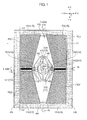
- FIG. 1 is an overall configuration diagram of the present optical scanner.
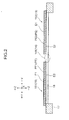
- Fig. 2 is a cross-sectional view of the optical scanner illustrated in Fig. 1 taken from a 2-2 direction.
- the present optical scanner is a MEMS optical scanner and comprises a mirror 11, a torsion bar (an example of a first shaft section) 12, a mirror frame 13, a shaft section 14 (an example of a second shaft section), a unimorph (an example of an actuator) 15, and an outer frame 17.
- a Y-axis vertical directions are represented by a Y-axis
- horizontal directions are represented by an X-axis
- directions perpendicular to the plane of paper are represented by a Z-axis.
- the Y-axis is positioned in a longitudinal direction of the torsion bar 12 and the X-axis passes through a center 0 of the mirror 11 and is positioned in a longitudinal direction of the shaft section 14.
- the X-axis, the Y-axis, and the Z-axis are respectively perpendicular to each other.
- the mirror 11 has a circular shape as seen in a -Z direction, and has a thin film made of aluminum or the like formed on a +Z direction-side surface for reflecting light from a light source or the like and scanning light in a horizontal scanning direction and a vertical scanning direction.
- Upper and lower torsion bars 12 are provided as a pair and have elongated shapes whose longitudinal direction is parallel to the Y-axis.
- the torsion bar formed on a +Y direction-side will be referred to as a torsion bar 121 and the torsion bar formed on a -Y direction-side will be referred to as a torsion bar 122.
- the longitudinal lengths of the torsion bars 121 and 122 are approximately the same.
- the mirror frame 13 holds the mirror 11 via the torsion bars 121 and 122 so as to be vibratable.
- the mirror frame 13 has an approximate rhombic shape whose outer circumference is left-right symmetrical about the Y-axis and up-down symmetrical about the X-axis, and is shaped so as to enclose the mirror 11.
- the weight of the mirror frame 13 is left-right symmetrical about the Y-axis and up-down symmetrical about the X-axis.
- each of the shaft sections 14 is constituted by a region at a central part of a base section 18 as seen in a +X direction.
- the base section 18 is a flexible plate-like member formed at a lower layer of a piezoelectric element PE that comprises a unimorph 15.
- the shaft section 14 Upon receiving a vibration force from the unimorph 15, the shaft section 14 deflects the mirror frame 13 in a +N direction or a -N direction around the X-axis and vibrates the mirror frame 13.
- the shaft section 14 positioned on the left side will be referred to as a shaft section 141 and the shaft section 14 positioned on the right side will be referred to as a shaft section 142.
- Fig. 3 is an enlarged view of the shaft section 141.
- the shaft section 141 comprises a main shaft section 143 and a connection section 144.
- the connection section 144 is configured so as to be deformable by forming a plurality of slits 145 whose longitudinal direction is the X-axis direction on the base section 18.
- the respective slits 145 are arranged so as to be up-down symmetrical about, for example, the X-axis. Accordingly, the flexibility of the shaft section 141 is arranged so as to be up-down symmetrical about the X-axis.
- the main shaft section 143 extends along the X-axis from the base section 18 to the mirror frame 13 and connects the mirror frame 13 with the connection section 144.
- connection section 144 provided on the shaft section 141 corresponds to an example of a left-side connection section and the connection section 144 provided on the shaft section 142 corresponds to an example of a right-side connection section.
- connection section 144 provided on the shaft section 142 corresponds to an example of a right-side connection section.
- pair of the left and right connection sections 144 corresponds to an example of a connection unit.
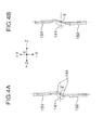
- Fig. 4 are diagrams illustrating an effect of the connection section 144, wherein Fig. 4(A) illustrates a case where the connection section 144 is provided on the shaft section 141 and Fig. 4(B) illustrates a case where the connection section 144 is not provided on the shaft section 141. Note that Fig. 4(A) and Fig. 4(B) illustrate the optical scanner as seen in the -X direction.
- connection section 144 When the connection section 144 is not provided on the shaft section 141 as illustrated in Fig. 4(B) , the shaft section 141 is not flexible and the unimorphs 151 and 152 are less likely to bend. Therefore, an angle of deflection of the mirror frame 13 around the X-axis decreases and the mirror 11 cannot deflect greatly around the X-axis.
- connection section 144 is provided on the shaft section 141 as illustrated in Fig. 4(A)
- the shaft section 141 becomes flexible and the unimorphs 151 and 152 are more likely to bend around the X-axis. Therefore, even when the same force as Fig. 4(B) is applied, an angle of deflection of the mirror frame 13 around the X-axis increases and the mirror 11 deflects greatly around the X-axis.
- a slit 131 perpendicular to the X-axis is formed on the mirror frame 13 in the vicinity of a connection point with the main shaft section 143. Therefore, a torsion bar 132 having the Y-axis direction as its longitudinal direction is formed in the vicinity of the connection point of the mirror frame 13 with the main shaft section 143. As a result, a portion between the mirror frame 13 and the main shaft section 143 is more likely to bend, and when the mirror frame 13 is deflected around the Y-axis, stress acting on the shaft section 141 is alleviated, thereby preventing damage to the shaft section 141.
- the unimorph 15 is constituted by four unimorphs 151, 152, 153, and 154 formed on upper left, lower left, upper right, and lower right sides, and holds the mirror frame 13 via the shaft section 14 so as to be vibratable.
- the unimorph 15 is configured by forming a piezoelectric element PE on an upper surface of the flexible base section 18.
- an electrode E1 is formed on a surface of the piezoelectric element PE
- an electrode E2 is formed on a base section 18 side of the piezoelectric element PE.
- the piezoelectric elements PE constituting the unimorphs 151 to 154 will be denoted as piezoelectric elements PE1 to PE4.
- +Y direction-side ends of the piezoelectric elements PE1 and PE3 are placed on a part of an upper outer frame 17 illustrated in Fig. 1
- -Y direction-side ends of the piezoelectric elements PE2 and PE4 are placed on a part of a lower outer frame 17 illustrated in Fig. 1 .
- the unimorph 15 can be extended or shortened.
- the unimorph 15 inclines toward the -Z direction-side
- the unimorph 15 inclines toward the +Z direction-side
- the unimorphs 151 and 153 incline toward the -Z direction-side and the unimorphs 152 and 154 incline toward the +Z direction-side.
- the unimorphs 151 to 154 can be vibrated around the X-axis.
- the mirror frame 13 and the mirror 11 vibrate around the X-axis.
- the unimorphs 151 and 152 incline toward the -Z direction-side and the unimorphs 153 and 154 incline toward the +Z direction-side.
- the unimorphs 151 to 154 can be vibrated around the Y-axis.
- the mirror frame 13 and the mirror 11 vibrate around the Y-axis.
- the mirror 11 and the mirror frame 13 can be vibrated in the same phase or in opposite phases around the Y-axis.
- the same phase represents that when the mirror frame 13 is deflected in the +N direction around the Y-axis, the mirror 11 deflects in the +N direction around the Y-axis
- opposite phases represent that when the mirror frame 13 is deflected in the +N direction around the Y-axis, the mirror 11 deflects in the -N direction around the Y-axis.
- a vibration of the mirror 11 and the mirror frame 13 in the same phase or in opposite phases around the Y-axis can be realized by adjusting dimensions and the like of the respective members comprising the optical scanner. Moreover, an experiment result shows that vibrating the mirror 11 and the mirror frame 13 in opposite phases around the Y-axis can increase the angle of deflection of the mirror 11 by a greater degree than vibrating the mirror 11 and the mirror frame 13 in the same phase. Therefore, in the present embodiment, the mirror 11 and the mirror frame 13 are vibrated in opposite phases around the Y-axis.
- the optical scanner is designed such that an angle of deflection of the mirror frame 13 about the Y-axis is smaller than an angle of deflection about the X-axis, by vibrating the mirror frame 13 at a resonant frequency of the mirror 11 and the mirror frame 13 when the mirror frame 13 is vibrated around the Y-axis as a rotational axis, the mirror 11 can be deflected at a relatively large angle of deflection.
- the resonant frequency has a value in the order of, for example, kHz that is a frequency of laser light in a horizontal scanning direction.
- the frequency of the mirror frame 13 in the X-axis direction has a value in the order of Hz that is a frequency of laser light in a vertical scanning direction.
- vibrations around the X-axis have a frequency in the vertical scanning direction of several 10 Hz and an acceleration acting on the mirror frame 13 is not significantly large, stress acting on the connection section 144 in this case is relatively small.
- connection section 144 since vibrations around the Y-axis have a frequency in the horizontal scanning direction of several 10 kHz and a significantly large acceleration acts on the mirror frame 13, stress acting on the connection section 144 in this case is significantly large. As a result, a problem arises in that a breakage of the connection section 144 occurs.
- connection section 144 when an amplitude of the unimorph 15 is increased in order to increase an angle of view in the horizontal scanning direction, the stress acting on the connection section 144 further increases and creates a risk of a breakage occurring at the connection section 144 despite the slit 131 being provided on the mirror frame 13, thereby making it difficult to obtain a large angle of deflection.
- an adjustment member 16 constituted by, for example, a weight for adjusting a moment of inertia of the mirror frame is provided on the mirror frame 13. Accordingly, the moment of inertia of the mirror frame 13 is increased in the Y-axis direction without having to increase the area of the mirror frame 13, a difference in maximum displacements between the mirror frame 13 and the unimorph 15 is reduced even when increasing the amplitude of the unimorph 15, and stress acting on the connection section 144 can be alleviated. Moreover, while increasing the area of the mirror frame 13 similarly increases the moment of inertia, a viscous resistance of the mirror frame 13 increases, making it difficult to vibrate the mirror frame 13 at high speed.
- Left and right adjustment members 16 about the Y axis are provided as a pair.
- the adjustment member 16 provided on the left side will be denoted as an adjustment member 161 and the adjustment member 16 provided on the right side will be denoted as an adjustment member 162.
- the adjustment members 161 and 162 are arranged on positions of the mirror frame 13 on the X axis separated from the Y axis by the same distance in the X-axis direction.
- the outer frame 17 is a frame body with a rectangular shape as seen in the -Z direction, and is formed by etching a semiconductor substrate and encloses the unimorph 15.
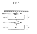
- Fig. 5 is a diagram illustrating a dynamic model of the optical scanner illustrated in Fig. 1 when the optical scanner is vibrated around the Y-axis.
- the dynamic model illustrated in Fig. 5 is a two-degree-of-freedom dynamic model, wherein a spring K1 represents the connection section 144, a mass M1 represents the mirror frame 13, a spring K2 represents the torsion bar 12, and a mass M2 represents the mirror 11.
- u1 denotes a displacement of the mirror frame 13 and u2 denotes a displacement of the mirror 11 when vibrated around the Y-axis
- the dynamic model illustrated in Fig. 5 may be expressed by the equation provided as Expression (1).
- Fig. 6 is a diagram of the optical scanner illustrated in Fig. 1 as seen in the -Y direction.
- Fig. 6(A) illustrates a case where the adjustment member 16 is not provided on the mirror frame 13
- Fig. 6(B) illustrates a case where the adjustment member 16 is provided on the mirror frame 13.
- a difference t between a maximum displacement of the unimorph 15 and a maximum displacement of the mirror frame 13 when vibrated around the Y-axis may be reduced.
- r indicated in Expression (1) is to be increased. Accordingly, the displacement u2 of the mirror 11 with respect to the displacement u1 of the mirror frame 13 is increased and the difference t can be reduced.
- adjustment members 161 and 162 are provided on the mirror frame 13 as illustrated in Fig. 6(B) so as to increase the moment of inertia ml. Accordingly, the value of r increases, thereby enabling the difference t between the maximum displacement of the unimorph 15 and the maximum displacement of the mirror frame 13 to be reduced without reducing the angle of deflection of the mirror. Therefore, the stress acting on the connection section 144 can be alleviated even when a large voltage is applied by the unimorph 15 to increase the angle of deflection of the mirror 11. As a result, the mirror 11 can be greatly deflected around the Y-axis and an angle of view in the horizontal scanning direction can be increased without damaging the shaft section 14 which is flexibly configured and which is susceptible to stress concentration.
- the optical scanner configured as described above is manufactured as follows using high-precision processing technology such as etching.
- a semiconductor substrate with a thickness of around 100 microns and which is constituted by, for example, silicon is processed into a shape including the outer frame 17 illustrated in Fig. 1 and the base section 18 illustrated in Fig. 2 .
- six holes H1 to H6 illustrated in Fig. 1 and the connection section 144 are formed on the semiconductor substrate. Accordingly, the mirror 11, the torsion bar 12, the mirror frame 13, the outer frame 17, the base section 18, and the like are formed.
- the hole H1 is a hole that demarcates the mirror 11 from the mirror frame 13 and is formed on the right side of the mirror 11.
- the hole H2 is a hole that demarcates the mirror 11 from the mirror frame 13 and is formed on the left side of the mirror 11.
- the hole H3 is a hole that demarcates the mirror frame 13 from the outer frame 17 and is formed on the upper side of the mirror frame 13.
- the hole H4 is a hole that demarcates the mirror frame 13 from the outer frame 17 and is formed on the lower side of the mirror frame 13.
- the hole H5 is a hole that demarcates the unimorphs 151 and 152 from the outer frame 17 and is formed on the left side of the unimorphs 151 and 152.
- the hole H6 is a hole that demarcates the unimorphs 153 and 154 from the outer frame 17 and is formed on the right side of the unimorphs 153 and 154.
- the adjustment members 161 and 162 are preferably configured using the same material as the piezoelectric elements PE. Accordingly, by abrading the thin film, the adjustment members 161 and 162 can be formed at the same time the piezoelectric elements PE1 to PE4 are formed, thereby enabling the manufacturing process to be simplified and productive efficiency to be improved.
- quartz SiO 2
- zinc oxide ZnO
- Rochelle salt potassium sodium tartrate
- lead zirconate titanate PZT: Pb(Zr, Ti)O 3
- lithium niobate LiNbO 3
- lithium tantalate LiTaO 3
- lithium tetraborate Li 2 B 4 O 7
- langasite La 3 Ga 5 SiO 14
- aluminum nitride aluminum nitride, tourmaline, polyvinylidene fluoride (PVDF), and the like
- PVDF polyvinylidene fluoride
- the adjustment members 161 and 162 are provided on a +Z direction-side surface of the mirror frame 13 in the above description, such an arrangement is not restrictive and the adjustment members 161 and 162 may alternatively be provided on a -Z direction-side surface of the mirror frame 13. Even in this case, the adjustment members 161 and 162 need only be provided on the X-axis at equal distances from the Y-axis. In addition, the adjustment members 161 and 162 may be provided on both the +Z direction-side surface and the -Z direction-side surface of the mirror frame 13. Furthermore, while the number of adjustment members 16 is set to two in the above description, for example, three or more adjustment members can be provided on the mirror frame 13. In this case, the same number of adjustment members is preferably provided on the left side and the right side of the mirror frame 13 so that the weight of the mirror frame 13 is uniformly-distributed with respect to the Y-axis.
- an actuator is not limited thereto.
- the present application can also be applied to an optical scanner arranged such that an actuator is driven by electromagnetic force or electrostatic force.
- a part of the mirror frame 13 may be processed so as to be thicker than other parts, whereby the thickened part is may be configured as the adjustment member 16.
- the adjustment member 16 since the adjustment member 16 is formed at the same time the mirror frame 13 is processed, productive efficiency can be improved.
- the optical scanner described above comprises: a mirror; a first shaft section; a mirror frame that holds the mirror via the first shaft section; a second shaft section that holds the mirror frame; and an actuator that vibrates the mirror around the first and second shaft sections by vibrating the mirror frame via the second shaft section, wherein the second shaft section includes a deformable connection unit and is connected to the actuator via the connection unit, and the mirror frame includes an adjustment member for adjusting moment of inertia.
- the mirror that scans light is held by the mirror frame via the first shaft section.
- the actuator is connected to the mirror frame via the second shaft section.
- the actuator vibrates the mirror around the first and second shaft sections.
- a deformable connection unit is formed at the second shaft section. Accordingly, the mirror frame deflects more readily around the second shaft section, and by a minute vibration of the actuator, the mirror can be greatly deflected around the second shaft section.
- the actuator vibrates the mirror around the first shaft section in addition to the second axis. Therefore, the vibration creates a problem in that stress concentrates at the connection unit and damages the second shaft section.
- the adjustment member is provided on the mirror frame. Accordingly, the moment of inertia of the mirror frame can be increased without having to increase the area of the mirror frame, a difference in maximum displacements between the mirror frame and the actuator can be reduced even when increasing the displacement of the mirror, and stress acting on the connection unit can be alleviated. Therefore, breakage of the second shaft section can be prevented.
- the mirror frame is weighted symmetrically about the first shaft section and the adjustment member is provided such that the mirror frame is weighted symmetrically about the first shaft section.
- displacement of the mirror frame around the first shaft section can be arranged so as to be symmetrical.
- the direction of the first shaft section is perpendicular to the direction of the second shaft section, and the adjustment member is provided on an extension of the second shaft section.
- a variance in moment of inertia of the mirror during vertical scanning in which the mirror frame is vibrated around the second shaft section can be reduced, thereby enabling the moment of inertia of the mirror to be adjusted without adversely affecting the vibration during vertical scanning.
- the optical scanner further comprises a base section constituted by a semiconducting material, wherein the actuator is constituted by a unimorph including a thin film of a piezoelectric element pasted on the base section, the adjustment member is constituted by a thin film of the same material as the piezoelectric element, and the mirror, the first shaft section, the mirror frame, and the second shaft section are constituted by the semiconducting material.
- the base section, the mirror, the first shaft section, the mirror frame, and the second shaft section can be formed, and by pasting a material for forming a piezoelectric element on surfaces of the base section, the mirror, the first shaft section, the mirror frame, and the second shaft section and etching the material, the piezoelectric element and the adjustment member that constitute the unimorph can be formed. Therefore, the piezoelectric element and the adjustment member that constitute the unimorph can be formed simultaneously and productive efficiency can be improved.
- a part of the mirror frame is thicker than other parts and the adjustment member is constituted by the part.
- the mirror frame is horizontally symmetrical about the first shaft section and vertically symmetrical about the second shaft section, and has a shape that encloses the mirror.
- the mirror frame since the mirror frame is left-right symmetrical and up-down symmetrical and has a shape that encloses the mirror, the mirror frame can be vertically and horizontally vibrated in a well-balanced manner, and the mirror can be vertically and horizontally vibrated in a well-balanced manner.
- connection unit comprises a plurality of slits whose longitudinal direction coincides with a longitudinal direction of the second shaft section.
- connection unit can be arranged so as to be deformable due to a simple configuration of forming a plurality of slits.
- the optical scanner further comprises an outer frame that encloses the actuator, wherein the connection unit is constituted by a pair of left and right connection sections, with the mirror frame being positioned in the center thereof, and the actuator includes an upper-left actuator connected between the left-side connection section and an upper part of the outer frame, a lower-left actuator connected between the left-side connection section and a lower part of the outer frame, an upper-right actuator connected between the right-side connection section and the upper part of the outer frame, and a lower-right actuator connected between the right-side connection section and the lower part of the outer frame.
- the actuator is constituted by four actuators, namely, the upper-left, the lower-left, the upper-right, and the lower-right actuators
- the mirror can be vibrated around the first shaft section.
- the mirror can be vibrated around the second shaft section.
Landscapes
- Engineering & Computer Science (AREA)
- Mechanical Engineering (AREA)
- Physics & Mathematics (AREA)
- Computer Hardware Design (AREA)
- Microelectronics & Electronic Packaging (AREA)
- General Physics & Mathematics (AREA)
- Optics & Photonics (AREA)
- Mechanical Optical Scanning Systems (AREA)
- Micromachines (AREA)
- Mechanical Light Control Or Optical Switches (AREA)
Applications Claiming Priority (2)
| Application Number | Priority Date | Filing Date | Title |
|---|---|---|---|
| JP2008245925 | 2008-09-25 | ||
| PCT/JP2009/066557 WO2010035759A1 (ja) | 2008-09-25 | 2009-09-24 | 光スキャナ |
Publications (2)
| Publication Number | Publication Date |
|---|---|
| EP2330456A1 true EP2330456A1 (de) | 2011-06-08 |
| EP2330456A4 EP2330456A4 (de) | 2012-04-11 |
Family
ID=42059757
Family Applications (1)
| Application Number | Title | Priority Date | Filing Date |
|---|---|---|---|
| EP09816174A Withdrawn EP2330456A4 (de) | 2008-09-25 | 2009-09-24 | Optischer scanner |
Country Status (4)
| Country | Link |
|---|---|
| US (1) | US8559089B2 (de) |
| EP (1) | EP2330456A4 (de) |
| JP (1) | JP5423680B2 (de) |
| WO (1) | WO2010035759A1 (de) |
Cited By (1)
| Publication number | Priority date | Publication date | Assignee | Title |
|---|---|---|---|---|
| EP4075183A1 (de) * | 2021-04-13 | 2022-10-19 | FUJIFILM Corporation | Mikrospiegelvorrichtung und optische abtastvorrichtung |
Families Citing this family (13)
| Publication number | Priority date | Publication date | Assignee | Title |
|---|---|---|---|---|
| US8559089B2 (en) | 2008-09-25 | 2013-10-15 | Konica Minolta Opto, Inc. | Optical scanner |
| JP5333286B2 (ja) * | 2010-02-23 | 2013-11-06 | セイコーエプソン株式会社 | 光スキャナーおよび画像形成装置 |
| JP5381801B2 (ja) * | 2010-02-23 | 2014-01-08 | セイコーエプソン株式会社 | 画像形成装置 |
| CN101950079A (zh) * | 2010-05-26 | 2011-01-19 | 香港应用科技研究院有限公司 | 具有可调谐振频率的双轴扫描镜面 |
| DE102012201981B4 (de) * | 2012-02-10 | 2020-08-20 | Robert Bosch Gmbh | Mikromechanisches Bauteil und Herstellungsverfahren für ein mikromechanisches Bauteil |
| JP6988062B2 (ja) * | 2016-08-02 | 2022-01-05 | 株式会社リコー | 光偏向器、光走査装置、画像投影装置、画像形成装置、および移動体 |
| WO2018179589A1 (ja) | 2017-03-30 | 2018-10-04 | 三菱電機株式会社 | 光走査装置およびその製造方法 |
| EP3872556A4 (de) | 2018-10-25 | 2021-12-08 | FUJIFILM Corporation | Mikrospiegelvorrichtung und verfahren zur ansteuerung einer mikrospiegelvorrichtung |
| CN109900221A (zh) * | 2019-04-12 | 2019-06-18 | 杭州思看科技有限公司 | 一种手持式三维扫描系统 |
| JP7354797B2 (ja) | 2019-11-27 | 2023-10-03 | 株式会社リコー | 光偏向器、偏向装置、距離測定装置、画像投影装置、及び車両 |
| JP7667041B2 (ja) * | 2021-09-08 | 2025-04-22 | 富士フイルム株式会社 | マイクロミラーデバイス及び光走査装置 |
| JP7693475B2 (ja) | 2021-09-08 | 2025-06-17 | 富士フイルム株式会社 | マイクロミラーデバイス及び光走査装置 |
| WO2024261200A1 (de) * | 2023-06-20 | 2024-12-26 | OQmented GmbH | Mems-vorrichtung mit einer haltestruktur umfassend eine federstruktur, innere rahmenstruktur und/oder hebelstruktur |
Family Cites Families (12)
| Publication number | Priority date | Publication date | Assignee | Title |
|---|---|---|---|---|
| JP4092283B2 (ja) * | 2003-11-17 | 2008-05-28 | スタンレー電気株式会社 | 2次元光スキャナ及び光学装置 |
| US7282775B2 (en) * | 2004-02-13 | 2007-10-16 | Advanced Numicro Systems, Inc. | MEMS scanning mirror with trenched surface and tapered comb teeth for reducing intertia and deformation |
| US7187488B2 (en) | 2005-03-09 | 2007-03-06 | Advanced Numicro Systems, Inc. | Trimming a MEMS device to fine tune natural frequency |
| JP2007199682A (ja) | 2005-12-27 | 2007-08-09 | Konica Minolta Holdings Inc | 光偏向器および光ビーム走査装置 |
| JP5151065B2 (ja) | 2006-05-19 | 2013-02-27 | コニカミノルタホールディングス株式会社 | 光スキャナ及び走査型プロジェクタ |
| US7557972B2 (en) | 2006-06-07 | 2009-07-07 | Canon Kabushiki Kaisha | Oscillator device, optical deflector and optical instrument using the same |
| JP5121301B2 (ja) | 2006-06-07 | 2013-01-16 | キヤノン株式会社 | 揺動体装置、光偏向器、及びそれを用いた光学機器 |
| JP4984117B2 (ja) | 2006-07-13 | 2012-07-25 | スタンレー電気株式会社 | 2次元光スキャナ、それを用いた光学装置および2次元光スキャナの製造方法 |
| JP4972774B2 (ja) | 2007-02-16 | 2012-07-11 | コニカミノルタアドバンストレイヤー株式会社 | マイクロスキャナおよびそれを備える光学機器 |
| JP2009098253A (ja) * | 2007-10-15 | 2009-05-07 | Panasonic Corp | 光学反射素子およびこれを用いた画像投影装置 |
| US8559089B2 (en) | 2008-09-25 | 2013-10-15 | Konica Minolta Opto, Inc. | Optical scanner |
| US8072664B1 (en) * | 2010-05-26 | 2011-12-06 | Hong Kong Applied Science & Technology Research Institute, Ltd. | Biaxial scanning mirror having resonant frequency adjustment |
-
2009
- 2009-09-24 US US13/120,203 patent/US8559089B2/en not_active Expired - Fee Related
- 2009-09-24 EP EP09816174A patent/EP2330456A4/de not_active Withdrawn
- 2009-09-24 WO PCT/JP2009/066557 patent/WO2010035759A1/ja not_active Ceased
- 2009-09-24 JP JP2010530859A patent/JP5423680B2/ja not_active Expired - Fee Related
Cited By (2)
| Publication number | Priority date | Publication date | Assignee | Title |
|---|---|---|---|---|
| EP4075183A1 (de) * | 2021-04-13 | 2022-10-19 | FUJIFILM Corporation | Mikrospiegelvorrichtung und optische abtastvorrichtung |
| US12360359B2 (en) | 2021-04-13 | 2025-07-15 | Fujifilm Corporation | Micromirror device and optical scanning device |
Also Published As
| Publication number | Publication date |
|---|---|
| US20110181933A1 (en) | 2011-07-28 |
| JP5423680B2 (ja) | 2014-02-19 |
| EP2330456A4 (de) | 2012-04-11 |
| US8559089B2 (en) | 2013-10-15 |
| JPWO2010035759A1 (ja) | 2012-02-23 |
| WO2010035759A1 (ja) | 2010-04-01 |
Similar Documents
| Publication | Publication Date | Title |
|---|---|---|
| US8559089B2 (en) | Optical scanner | |
| AU2007305711B2 (en) | Optical scanning device | |
| JP5319939B2 (ja) | 光偏向器および光学装置 | |
| JP4092283B2 (ja) | 2次元光スキャナ及び光学装置 | |
| JP4385938B2 (ja) | アクチュエータ | |
| US20130063800A1 (en) | Mirror driving apparatus, method of driving same and method of manufacturing same | |
| CN104570335B (zh) | 光扫描仪、图像显示装置、头戴式显示器以及平视显示器 | |
| CN101135774A (zh) | 微振荡元件 | |
| CN104236534B (zh) | 压电装置及电子设备 | |
| JP2005128147A (ja) | 光偏向器及び光学装置 | |
| CN102695978A (zh) | 振动反射镜元件及振动反射镜元件的制造方法 | |
| US20120008185A1 (en) | Light beam scanning device | |
| US7095156B2 (en) | Actuator | |
| JP2849697B2 (ja) | 2自由度振動型マイクロアクチュエータ | |
| US8804223B2 (en) | Light beam scanning device with a silicon mirror on a metal substrate | |
| JP4983648B2 (ja) | 光走査装置 | |
| US7926369B2 (en) | Actuator | |
| JP2014092630A (ja) | 光走査装置および製造方法 | |
| CN111149372B (zh) | 超声波传感器 | |
| JP2009186721A (ja) | 光学反射素子 | |
| EP3961289A1 (de) | Mikrospiegelvorrichtung | |
| JP5298985B2 (ja) | 光走査装置 | |
| JP2014202801A (ja) | 光学反射素子 | |
| JP4446345B2 (ja) | 光偏向素子と光偏向器と光走査装置及び画像形成装置 | |
| JP2008068369A (ja) | アクチュエータ、光スキャナ、および画像形成装置 |
Legal Events
| Date | Code | Title | Description |
|---|---|---|---|
| PUAI | Public reference made under article 153(3) epc to a published international application that has entered the european phase |
Free format text: ORIGINAL CODE: 0009012 |
|
| 17P | Request for examination filed |
Effective date: 20110328 |
|
| AK | Designated contracting states |
Kind code of ref document: A1 Designated state(s): AT BE BG CH CY CZ DE DK EE ES FI FR GB GR HR HU IE IS IT LI LT LU LV MC MK MT NL NO PL PT RO SE SI SK SM TR |
|
| AX | Request for extension of the european patent |
Extension state: AL BA RS |
|
| DAX | Request for extension of the european patent (deleted) | ||
| A4 | Supplementary search report drawn up and despatched |
Effective date: 20120314 |
|
| RIC1 | Information provided on ipc code assigned before grant |
Ipc: G02B 26/08 20060101ALI20120308BHEP Ipc: B81B 3/00 20060101ALI20120308BHEP Ipc: G02B 26/10 20060101AFI20120308BHEP |
|
| 17Q | First examination report despatched |
Effective date: 20140115 |
|
| STAA | Information on the status of an ep patent application or granted ep patent |
Free format text: STATUS: THE APPLICATION IS DEEMED TO BE WITHDRAWN |
|
| 18D | Application deemed to be withdrawn |
Effective date: 20170824 |