EP2330713A2 - Système de charge de batterie doté d'une alimentation limitée en courant - Google Patents
Système de charge de batterie doté d'une alimentation limitée en courant Download PDFInfo
- Publication number
- EP2330713A2 EP2330713A2 EP10190052A EP10190052A EP2330713A2 EP 2330713 A2 EP2330713 A2 EP 2330713A2 EP 10190052 A EP10190052 A EP 10190052A EP 10190052 A EP10190052 A EP 10190052A EP 2330713 A2 EP2330713 A2 EP 2330713A2
- Authority
- EP
- European Patent Office
- Prior art keywords
- battery
- power supply
- current
- load
- output
- Prior art date
- Legal status (The legal status is an assumption and is not a legal conclusion. Google has not performed a legal analysis and makes no representation as to the accuracy of the status listed.)
- Withdrawn
Links
Images


Classifications
-
- H—ELECTRICITY
- H02—GENERATION; CONVERSION OR DISTRIBUTION OF ELECTRIC POWER
- H02J—ELECTRIC POWER NETWORKS; CIRCUIT ARRANGEMENTS OR SYSTEMS FOR SUPPLYING OR DISTRIBUTING ELECTRIC POWER; SYSTEMS FOR STORING ELECTRIC ENERGY
- H02J7/00—Circuit arrangements for charging or discharging batteries or for supplying loads from batteries
- H02J7/865—Battery or charger load switching, e.g. concurrent charging and load supply
-
- H—ELECTRICITY
- H02—GENERATION; CONVERSION OR DISTRIBUTION OF ELECTRIC POWER
- H02J—ELECTRIC POWER NETWORKS; CIRCUIT ARRANGEMENTS OR SYSTEMS FOR SUPPLYING OR DISTRIBUTING ELECTRIC POWER; SYSTEMS FOR STORING ELECTRIC ENERGY
- H02J7/00—Circuit arrangements for charging or discharging batteries or for supplying loads from batteries
- H02J7/14—Circuit arrangements for charging or discharging batteries or for supplying loads from batteries for charging batteries from dynamo-electric generators driven at varying speed, e.g. on vehicle
- H02J7/1438—Circuit arrangements for charging or discharging batteries or for supplying loads from batteries for charging batteries from dynamo-electric generators driven at varying speed, e.g. on vehicle in combination with power supplies for loads other than batteries
-
- H—ELECTRICITY
- H02—GENERATION; CONVERSION OR DISTRIBUTION OF ELECTRIC POWER
- H02J—ELECTRIC POWER NETWORKS; CIRCUIT ARRANGEMENTS OR SYSTEMS FOR SUPPLYING OR DISTRIBUTING ELECTRIC POWER; SYSTEMS FOR STORING ELECTRIC ENERGY
- H02J7/00—Circuit arrangements for charging or discharging batteries or for supplying loads from batteries
- H02J7/34—Parallel operation in networks using both storage and other DC sources, e.g. providing buffering
-
- H—ELECTRICITY
- H02—GENERATION; CONVERSION OR DISTRIBUTION OF ELECTRIC POWER
- H02J—ELECTRIC POWER NETWORKS; CIRCUIT ARRANGEMENTS OR SYSTEMS FOR SUPPLYING OR DISTRIBUTING ELECTRIC POWER; SYSTEMS FOR STORING ELECTRIC ENERGY
- H02J7/00—Circuit arrangements for charging or discharging batteries or for supplying loads from batteries
- H02J7/02—Circuit arrangements for charging or discharging batteries or for supplying loads from batteries for charging batteries from AC mains by converters
- H02J7/04—Regulation of charging current or voltage
-
- H—ELECTRICITY
- H02—GENERATION; CONVERSION OR DISTRIBUTION OF ELECTRIC POWER
- H02J—ELECTRIC POWER NETWORKS; CIRCUIT ARRANGEMENTS OR SYSTEMS FOR SUPPLYING OR DISTRIBUTING ELECTRIC POWER; SYSTEMS FOR STORING ELECTRIC ENERGY
- H02J7/00—Circuit arrangements for charging or discharging batteries or for supplying loads from batteries
- H02J7/14—Circuit arrangements for charging or discharging batteries or for supplying loads from batteries for charging batteries from dynamo-electric generators driven at varying speed, e.g. on vehicle
- H02J7/1415—Circuit arrangements for charging or discharging batteries or for supplying loads from batteries for charging batteries from dynamo-electric generators driven at varying speed, e.g. on vehicle with a generator driven by a prime mover other than the motor of a vehicle
-
- H—ELECTRICITY
- H02—GENERATION; CONVERSION OR DISTRIBUTION OF ELECTRIC POWER
- H02J—ELECTRIC POWER NETWORKS; CIRCUIT ARRANGEMENTS OR SYSTEMS FOR SUPPLYING OR DISTRIBUTING ELECTRIC POWER; SYSTEMS FOR STORING ELECTRIC ENERGY
- H02J7/00—Circuit arrangements for charging or discharging batteries or for supplying loads from batteries
- H02J7/90—Regulation of charging or discharging current or voltage
-
- Y—GENERAL TAGGING OF NEW TECHNOLOGICAL DEVELOPMENTS; GENERAL TAGGING OF CROSS-SECTIONAL TECHNOLOGIES SPANNING OVER SEVERAL SECTIONS OF THE IPC; TECHNICAL SUBJECTS COVERED BY FORMER USPC CROSS-REFERENCE ART COLLECTIONS [XRACs] AND DIGESTS
- Y02—TECHNOLOGIES OR APPLICATIONS FOR MITIGATION OR ADAPTATION AGAINST CLIMATE CHANGE
- Y02T—CLIMATE CHANGE MITIGATION TECHNOLOGIES RELATED TO TRANSPORTATION
- Y02T10/00—Road transport of goods or passengers
- Y02T10/60—Other road transportation technologies with climate change mitigation effect
- Y02T10/70—Energy storage systems for electromobility, e.g. batteries
Definitions
- the battery charging coaction and output system with current limit supply relates to a power system utilizing an engine generator or public power with AC source, wherein the power system particularly has the characteristics that the maximum output current thereof is limited by electromagnetic effects, and/or constant current or nearly constant current output thereof is set to be lower than the maximum output current, for powering a load, and timely supporting charging a setting type or vehicle type battery, or jointly powering a load with a battery; when an engine generator set is utilized to be power supply, during operation, the engine operates with the best brake specific fuel consumption and/or the range of revolutions and torque for better energy saving.
- Battery developed to date, by reason of its convenience for carriage from one place to another and volumetric density, up to utility level, is nowadays frequently used for purpose of emergency power storage, or as a means of power supply to motor driven implements, power driven tooling or more generally as a DC power supply; the pity, however, is that where power supply is required for a prolonged term, or where efforts to enlarge dimensionally a battery would inevitably involve cost increases or weight increases, or still, where exposed to working at a more profound discharge depth the battery would suffer from a shortened service term.
- the present invention relates to a power system utilizing an engine generator or public power with AC source, wherein the power system particularly has the characteristics that the maximum output current thereof is limited by electromagnetic effects, and/or constant current or nearly constant current output thereof is set to be lower than the maximum output current, for powering a load, and charging a battery, or jointly powering a load with a battery; when an engine generator set is utilized to be power supply, during operation, the engine operates with the best brake specific fuel consumption and/or the range of revolutions and torque for better energy saving.
- the battery charging coaction and output system with current limit supply relates to a power system utilizing an engine generator or public power with AC source, wherein the power system particularly has the characteristics that the maximum output current thereof is limited by electromagnetic effects, and/or constant current or nearly constant current output thereof is set to be lower than the maximum output current, for powering a load, and timely supporting charging a setting type or vehicle type battery, or jointly powering a load with a battery; when an engine generator set is utilized to be power supply, during operation, the engine operates with the best brake specific fuel consumption and/or the range of revolutions and torque for better energy saving.
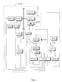
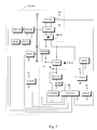
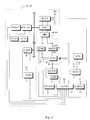
- Fig. 1 is a system block diagram of the battery charging coaction and output system with current limit supply, and the main components are explained as following:
- auxiliary power supply in the form of DC charge converted from an AC line feeder, as the auxiliary power supply (PS100), so as to drive a load motor (or other loads), and for timely supporting charging a setting type, vehicle type, or portable battery; in operation, testing measurement is made, basing on a manual control device, or else on a central control unit programmed for the purpose with battery storage condition taken into account, whereby circuit testing signal value is compared with aforementioned controlled or setting value, and that bringing about proportionate, controlled operation of the engine driven generation set or the auxiliary power supply (PS100) in the form of DC charge converted from an AC line feeder, incorporating optionally various functions including any or all of the following:
- the battery wherever mentioned hereinbefore, is executed where appropriate, either fixed as an installation in a circuit, or as a mobile, removable installation in a plug/socket assembly or otherwise combination form, associated with the primary circuit, featuring: (1) charging of the battery (BAT101) the AC to DC mode; (2) charging of the battery (BAT101) by DC converted from AC, and the same current as input of power to the load; (3) charging of the battery (BAT101) by DC converted from AC and the same current by way of the battery (BAT101) delivering power to the load; (4) the battery (BAT101) singly delivering power eventually to the load; and (5) the battery (BAT101) functioning as a filter, whereof that output terminal going to the load side is optionally equipped with a drive control (CD101) serving to control output voltage or output current or output polarity or serving to protect in the event of an overloading condition, by activating the associated control circuits.
- a drive control CD101
- Fig. 5 is a schematic block diagram showing the circuit of the auxiliary power supply (PS100) which consists of the DC charge converted from an AC line voltage, according to the present invention; it will be appreciated that the incoming AC power source, gone through the output terminal of the magnetic flux leakage transformer (CCT100), thence a rectifier (BR201), serves forthwith as the power supply (VM+) to the motor or otherwise load, on the one hand, a regulator serves as the charging power supply (VB+) to the battery (BAT101), on the other hand, both power supplies defined as such constitutes the auxiliary power supply (PS100), whereas the regulator (RG101) in series with the DC output of the auxiliary power supply, constituted of analogy or wave interceptor circuits, serving to restrict charging current to the battery (BAT101), of which the positive output terminal (VB+) is fed to the power side (VM+) of motor by way of a forward, serially connected diode (CR201), the battery mentioned in the foregoing is executed where appropriate, either fixed as an installation in a
- Fig. 6 is a schematic block diagram showing the circuit in which a magnetic flux leakage transformer (CCT100) and two sets of rectification circuits, which are equal voltages, are respectively serving as motor driven power supply or battery charging power supply, according to the present invention; in which it will be seen two sets of auxiliary power supply in the form of DC charge converted from AC source by way of rectifiers (BR201) and (BR202), with one set serving as the charging power supply (VM+) to the motor or other load, on the one hand, another set serving as the charging power supply (VB+) to the battery (BAT101); the magnetic flux leakage transformer (CCT100) is installed between the rectifier (BR201) and the incoming AC source, to restrict charging current to the motor or other loads; and the magnetic flux leakage transformer (CCT100) is installed between the rectifier (BR202) and the AC source, so as to restrict charging current to the battery (BAT101), whereof the positive output terminal (VB+) is given in forward series with a diode (CR201), leading to the power
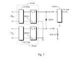
- Fig. 7 is schematic block diagram showing the circuit in which different power supplies individually equipped with a rectifier set, and the individual magnetic flux leakage transformer (CCT100) are respectively serving as motor driven power supply or battery charging power supply, according to the present invention; in which are represented circuit schematics for the supply of different AC voltage by way of two independent secondary winding or tap winding sets of the magnetic flux leakage transformer (CCT100), and two sets of rectifier circuits and exclusively independent regulators by which the motor driving power supply and the battery charging power supply are governed; as shown in the Fig.7 , there are two sets of auxiliary power supply in the form of DC charge converted from AC source by way of rectifiers (BR201) and BR202, with one set serving as the power supply to drive motor or otherwise load, designated (VM+), and the other set accounting for the power supply (VB+) to charge battery (BAT101); the magnetic flux leakage transformer (CCT100) is installed between the rectifier (BR201) and the incoming AC source, to restrict charging current to the motor or other loads, whereof the positive
Landscapes
- Engineering & Computer Science (AREA)
- Power Engineering (AREA)
- Charge And Discharge Circuits For Batteries Or The Like (AREA)
- Control Of Eletrric Generators (AREA)
- Secondary Cells (AREA)
- Control Of Charge By Means Of Generators (AREA)
Applications Claiming Priority (3)
| Application Number | Priority Date | Filing Date | Title |
|---|---|---|---|
| US12/591,025 US8552588B2 (en) | 2009-11-05 | 2009-11-05 | Battery charging coaction and output system with current limit supply |
| CN200910212363.0A CN102055232B (zh) | 2009-11-05 | 2009-11-06 | 限电流电源的电瓶充电及协力输出系统 |
| CN2009202664389U CN201663472U (zh) | 2009-11-05 | 2009-11-06 | 限电流电源的电瓶充电及协力输出系统 |
Publications (2)
| Publication Number | Publication Date |
|---|---|
| EP2330713A2 true EP2330713A2 (fr) | 2011-06-08 |
| EP2330713A3 EP2330713A3 (fr) | 2014-10-29 |
Family
ID=50437532
Family Applications (1)
| Application Number | Title | Priority Date | Filing Date |
|---|---|---|---|
| EP10190052.0A Withdrawn EP2330713A3 (fr) | 2009-11-05 | 2010-11-04 | Système de charge de batterie doté d'une alimentation limitée en courant |
Country Status (11)
| Country | Link |
|---|---|
| US (1) | US8552588B2 (fr) |
| EP (1) | EP2330713A3 (fr) |
| JP (1) | JP5679772B2 (fr) |
| KR (1) | KR20120063003A (fr) |
| CN (2) | CN102055232B (fr) |
| AU (1) | AU2010241243B2 (fr) |
| BR (1) | BRPI1004666B1 (fr) |
| CA (1) | CA2719773C (fr) |
| DE (1) | DE202010015132U1 (fr) |
| RU (1) | RU2543504C2 (fr) |
| TW (2) | TWM416930U (fr) |
Cited By (1)
| Publication number | Priority date | Publication date | Assignee | Title |
|---|---|---|---|---|
| CN105024451A (zh) * | 2015-08-10 | 2015-11-04 | 广州三晶电气有限公司 | 自动切换供电电源的辅助电源装置及其光伏并网逆变器 |
Families Citing this family (43)
| Publication number | Priority date | Publication date | Assignee | Title |
|---|---|---|---|---|
| US8552588B2 (en) * | 2009-11-05 | 2013-10-08 | Tai-Her Yang | Battery charging coaction and output system with current limit supply |
| US9172247B2 (en) * | 2010-03-24 | 2015-10-27 | Panasonic Intellectual Property Management Co., Ltd. | Power supply system with controlled power storage |
| JP5185993B2 (ja) * | 2010-12-01 | 2013-04-17 | 三菱電機株式会社 | 車両用発電制御装置 |
| EP2521241B1 (fr) * | 2011-05-05 | 2014-05-21 | VEGA Grieshaber KG | Appareil de champ avec un dispositif de régulation de courant de charge |
| WO2012172567A1 (fr) * | 2011-06-17 | 2012-12-20 | Valagam Rajagopal Raghunathan | Appareils intelligents |
| US9425727B2 (en) | 2012-04-17 | 2016-08-23 | Kohler Co. | Charging an energy storage device with a variable speed generator |
| US8963508B2 (en) | 2012-04-19 | 2015-02-24 | Kohler Co. | Method of controlling speed of a variable speed generator |
| US9219294B2 (en) | 2012-08-22 | 2015-12-22 | Eric D. Albsmeier | Power management system that changes the operating conditions of a battery charger |
| US9331498B2 (en) | 2012-09-07 | 2016-05-03 | Kohler Co. | Power generation system that provides efficient battery charger selection |
| US8829855B2 (en) | 2012-09-26 | 2014-09-09 | Kohler Co. | Power generation system that optimizes the power provided to start a generator |
| US9178373B2 (en) * | 2013-02-08 | 2015-11-03 | Canadus Power Systems, Llc | Alternator control system and method |
| WO2014135947A1 (fr) * | 2013-03-06 | 2014-09-12 | Bombardier Inc. | Système de freinage électrique et procédé reposant sur l'hystérésis de tension pour une commande de puissance de freinage appliquée |
| CN103612569B (zh) * | 2013-06-08 | 2016-06-15 | 苏州市莱赛电车技术有限公司 | 一种电动车用电源系统 |
| DE102014207759A1 (de) | 2013-07-03 | 2015-01-08 | Continental Automotive Gmbh | Stromsensor-Shunt mit Bohrungen für Press-Fit-Pins |
| US20150042267A1 (en) * | 2013-08-12 | 2015-02-12 | O2Micro Inc. | System and Method for Controlling a Battery |
| DE102015102163B4 (de) * | 2014-02-18 | 2021-01-28 | Subaru Corporation | Batteriespannungs-Steuerung und Verfahren zur Steuerung einer Batteriespannung |
| DE102014207756A1 (de) | 2014-04-24 | 2015-10-29 | Continental Automotive Gmbh | Shuntstrommessung mit Temperaturkompensation |
| DE102015217898A1 (de) | 2014-09-17 | 2016-03-17 | Continental Teves Ag & Co. Ohg | Verfahren zum kontinuierlichen Kalibrieren von Strommesssystemen in Kraftfahrzeugen |
| DE102014218708A1 (de) | 2014-09-17 | 2016-03-17 | Continental Teves Ag & Co. Ohg | Shuntstrommessung mit Temperaturkompensation |
| MX2017001370A (es) | 2014-09-17 | 2017-11-20 | Continental Teves Ag & Co Ohg | Calibracion de detectores de corriente por medio de una corriente de referencia durante la medicion de la corriente. |
| US9537405B2 (en) * | 2014-09-29 | 2017-01-03 | Power Integrations, Inc. | Power converter with power foldback |
| US9649944B2 (en) * | 2015-04-21 | 2017-05-16 | Atieva, Inc. | Method of providing constant driving range in an electric vehicle |
| US9845806B2 (en) * | 2015-06-04 | 2017-12-19 | United Technologies Corporation | Engine speed optimization as a method to reduce APU fuel consumption |
| TWI558052B (zh) * | 2015-07-16 | 2016-11-11 | Nat Univ Chung Hsing | Regenerative energy control methods and systems |
| DE102016112836A1 (de) * | 2016-06-14 | 2017-12-14 | Leander Kilian Gross | Verfahren und Vorrichtung zur thermischen Behandlung eines Substrats |
| RU2656357C1 (ru) * | 2017-07-18 | 2018-06-05 | Руслан Анатольевич Травников | Система адаптивного управления элементами (оборудованием, устройствами) системы электропитания электрической нагрузки, подключённой к двум и более источникам электрической энергии (варианты) |
| CN109286238A (zh) * | 2017-07-23 | 2019-01-29 | 光宝科技股份有限公司 | 电源供应装置 |
| TWI642566B (zh) * | 2017-11-13 | 2018-12-01 | 中華汽車工業股份有限公司 | Car motor with built-in charge control function |
| US10559962B2 (en) * | 2018-01-06 | 2020-02-11 | Aic Inc. | Power-outputting management method for power-supplying apparatus |
| WO2019138261A1 (fr) * | 2018-01-12 | 2019-07-18 | Carrier Corporation | Architecture et procédé pour chargeur de batterie à double tension de sortie et gestion de charge pour une unité de réfrigération de transport |
| RU2679828C1 (ru) * | 2018-02-06 | 2019-02-13 | ЭйАйСи ИНК. | Способ управления выходной мощностью для блока питания |
| US10589635B1 (en) * | 2019-03-01 | 2020-03-17 | The Boeing Company | Active voltage control for hybrid electric aircraft |
| KR102305054B1 (ko) * | 2020-01-30 | 2021-09-27 | (주)미섬시스텍 | 배터리관리시스템(bms)의 전원공급 자동 제어 장치 및 방법 |
| RU201100U1 (ru) * | 2020-02-26 | 2020-11-26 | Общество с ограниченной ответственностью "РД-ХЕЛИ" | Мобильная зарядная станция постоянного тока для быстрого заряда электрических транспортных средств |
| CN113746189A (zh) * | 2020-05-29 | 2021-12-03 | 天扬精密科技股份有限公司 | 启动电池与快速储能模块并联出力比配置系统及其方法 |
| EP4147112A1 (fr) * | 2020-09-04 | 2023-03-15 | Google LLC | Atténuation de charge inégale dans un dispositif informatique mobile ayant de multiples dispositifs de stockage d'énergie |
| JP7060896B1 (ja) * | 2021-05-24 | 2022-04-27 | 東洋システム株式会社 | バッテリ充放電試験装置及びバッテリ放電電力制御方法 |
| CN113540520B (zh) * | 2021-07-23 | 2022-10-21 | 成都亿华通动力科技有限公司 | 一种双电堆的异步启动方法及装置 |
| CN114184975B (zh) * | 2021-11-29 | 2023-10-27 | 国网北京市电力公司 | 一种交流充电桩测试仪的检测装置 |
| CN117686803A (zh) * | 2022-09-09 | 2024-03-12 | 株洲变流技术国家工程研究中心有限公司 | 一种船舶推进试验平台 |
| CN116674425B (zh) * | 2023-06-07 | 2023-12-01 | 湖南文理学院 | 一种基于总量一致的动力电池组协同控制方法及系统 |
| CN116488322B (zh) * | 2023-06-25 | 2023-09-12 | 中铁电气化铁路运营管理有限公司 | 并联型低压大电流输出的直流电源装置及控制方法 |
| TWI862067B (zh) * | 2023-08-08 | 2024-11-11 | 台達電子工業股份有限公司 | 電網系統及電網控制方法 |
Citations (4)
| Publication number | Priority date | Publication date | Assignee | Title |
|---|---|---|---|---|
| JPS59198802A (ja) * | 1983-04-21 | 1984-11-10 | Mitsubishi Heavy Ind Ltd | 産業用車両 |
| US5714874A (en) * | 1993-09-06 | 1998-02-03 | Imra Europe Sa | Fuel cell voltage generator |
| US20040041568A1 (en) * | 2002-03-22 | 2004-03-04 | Tai-Her Yang | Automatic surveillant revolving storage battery auxiliary charging system |
| US7199552B2 (en) * | 2004-01-16 | 2007-04-03 | Sony Corporation | Control circuit apparatus and power supply circuit control method |
Family Cites Families (17)
| Publication number | Priority date | Publication date | Assignee | Title |
|---|---|---|---|---|
| US3673379A (en) * | 1970-03-20 | 1972-06-27 | Richard F Eversull | Motor vehicle warm-up and battery charger system |
| DE4102150A1 (de) * | 1991-01-25 | 1992-07-30 | Audi Ag | Verfahren zur steuerung eines generators |
| JP3435708B2 (ja) * | 1992-07-07 | 2003-08-11 | 株式会社デンソー | 車両用交流発電機の電圧制御装置 |
| TW203669B (en) * | 1992-07-24 | 1993-04-11 | Tay-Her Yang | Direct current series or multiple exciting electric machine with detecting and monitoring functions |
| JPH06296302A (ja) * | 1993-02-15 | 1994-10-21 | Toyota Motor Corp | 電気自動車用エンジン駆動発電機の制御装置 |
| CN1055574C (zh) * | 1996-03-06 | 2000-08-16 | 杨泰和 | 自动监控运转之引擎驱动式蓄电瓶辅助充电系统 |
| TW332944B (en) * | 1997-04-25 | 1998-06-01 | Tay-Her Yang | The engine-driving type battery auxiliary-recharging system |
| CN1145087C (zh) * | 1999-05-14 | 2004-04-07 | 精工爱普生株式会社 | 电子设备及用于电子设备的控制方法 |
| SG92711A1 (en) * | 1999-06-07 | 2002-11-19 | Zip Charge Corp | Electrical vehicle energy supply system, electrical vehicle battery, electrical vehicle battery charging apparatus, battery supply apparatus, and electrical vehicle battery management system |
| US6172478B1 (en) * | 2000-02-23 | 2001-01-09 | Telxon Corporation | Power distribution in a portable device |
| RU2305349C2 (ru) * | 2005-10-17 | 2007-08-27 | Федеральное государственное унитарное предприятие "Научно-производственное объединение прикладной механики им. акад. М.Ф. Решетнева" | Способ эксплуатации никель-водородной аккумуляторной батареи в составе геостационарного искусственного спутника земли |
| RU2323508C2 (ru) * | 2005-10-17 | 2008-04-27 | Александр Иванович Груздев | Комбинированный электрохимический источник тока |
| RU70056U1 (ru) * | 2007-03-06 | 2008-01-10 | Владимир Николаевич Уваров | Устройство для заряда аккумуляторной батареи |
| RU2368985C2 (ru) * | 2007-09-17 | 2009-09-27 | ОАО "Аккумуляторная компания "Ригель" | Способ эксплуатации никель-металлогидридных буферных батарей на электромобилях |
| DE102007054396A1 (de) * | 2007-11-14 | 2009-05-20 | Robert Bosch Gmbh | Batterie, insbesondere für ein Kraftfahrzeug, mit einer Vorrichtung und einem Verfahren zum Laden der Batterie |
| JP4254899B1 (ja) * | 2008-02-13 | 2009-04-15 | トヨタ自動車株式会社 | ハイブリッド自動車およびその制御方法 |
| US8552588B2 (en) * | 2009-11-05 | 2013-10-08 | Tai-Her Yang | Battery charging coaction and output system with current limit supply |
-
2009
- 2009-11-05 US US12/591,025 patent/US8552588B2/en active Active
- 2009-11-06 CN CN200910212363.0A patent/CN102055232B/zh active Active
- 2009-11-06 CN CN2009202664389U patent/CN201663472U/zh not_active Expired - Lifetime
- 2009-11-06 TW TW098220577U patent/TWM416930U/zh unknown
- 2009-11-06 TW TW098137725A patent/TWI502850B/zh active
-
2010
- 2010-11-02 CA CA2719773A patent/CA2719773C/fr active Active
- 2010-11-03 RU RU2010145118/07A patent/RU2543504C2/ru active
- 2010-11-04 DE DE202010015132U patent/DE202010015132U1/de not_active Expired - Lifetime
- 2010-11-04 AU AU2010241243A patent/AU2010241243B2/en not_active Ceased
- 2010-11-04 EP EP10190052.0A patent/EP2330713A3/fr not_active Withdrawn
- 2010-11-05 JP JP2010248383A patent/JP5679772B2/ja active Active
- 2010-11-05 BR BRPI1004666-6A patent/BRPI1004666B1/pt active IP Right Grant
- 2010-12-07 KR KR1020100123988A patent/KR20120063003A/ko not_active Ceased
Patent Citations (4)
| Publication number | Priority date | Publication date | Assignee | Title |
|---|---|---|---|---|
| JPS59198802A (ja) * | 1983-04-21 | 1984-11-10 | Mitsubishi Heavy Ind Ltd | 産業用車両 |
| US5714874A (en) * | 1993-09-06 | 1998-02-03 | Imra Europe Sa | Fuel cell voltage generator |
| US20040041568A1 (en) * | 2002-03-22 | 2004-03-04 | Tai-Her Yang | Automatic surveillant revolving storage battery auxiliary charging system |
| US7199552B2 (en) * | 2004-01-16 | 2007-04-03 | Sony Corporation | Control circuit apparatus and power supply circuit control method |
Cited By (1)
| Publication number | Priority date | Publication date | Assignee | Title |
|---|---|---|---|---|
| CN105024451A (zh) * | 2015-08-10 | 2015-11-04 | 广州三晶电气有限公司 | 自动切换供电电源的辅助电源装置及其光伏并网逆变器 |
Also Published As
| Publication number | Publication date |
|---|---|
| TW201117520A (en) | 2011-05-16 |
| AU2010241243B2 (en) | 2015-11-19 |
| CA2719773C (fr) | 2017-07-18 |
| EP2330713A3 (fr) | 2014-10-29 |
| AU2010241243A1 (en) | 2011-05-19 |
| TWM416930U (en) | 2011-11-21 |
| CN201663472U (zh) | 2010-12-01 |
| CA2719773A1 (fr) | 2011-05-05 |
| CN102055232A (zh) | 2011-05-11 |
| JP5679772B2 (ja) | 2015-03-04 |
| US8552588B2 (en) | 2013-10-08 |
| JP2011152028A (ja) | 2011-08-04 |
| BRPI1004666B1 (pt) | 2020-10-06 |
| BRPI1004666A2 (pt) | 2013-02-26 |
| CN102055232B (zh) | 2014-09-17 |
| TWI502850B (zh) | 2015-10-01 |
| KR20120063003A (ko) | 2012-06-15 |
| DE202010015132U1 (de) | 2011-04-28 |
| RU2010145118A (ru) | 2012-05-10 |
| US20110101778A1 (en) | 2011-05-05 |
| RU2543504C2 (ru) | 2015-03-10 |
Similar Documents
| Publication | Publication Date | Title |
|---|---|---|
| CA2719773C (fr) | Systeme a coaction et de sortie de charge de batterie avec alimentation a limite de courant | |
| EP1513239A1 (fr) | Chargeur automatique pour une pile auxiliaire | |
| EP2306614B1 (fr) | Système de surveillance automatique de la charge tournante d'une batterie de réserve | |
| US7554214B2 (en) | Large transient detection for electric power generation | |
| EP2259422B1 (fr) | Système de démarrage/génération doté d'un disjoncteur polyvalent | |
| KR20180066002A (ko) | 전류를 제한하여 전력을 공급하는 배터리 충전용 협력 및 출력 시스템 | |
| CN107695483B (zh) | 双电池混合动力发动机驱动焊机以及控制其的方法和系统 | |
| CN109256571B (zh) | 具有燃料电池的机动车辆 | |
| CN101801762B (zh) | 电动转向装置 | |
| JP2011256827A (ja) | 電源システム | |
| CN106103331B (zh) | 起重机装置、电力供给单元及改造方法 | |
| JP5192170B2 (ja) | 発電制御装置及び鞍乗型車両 | |
| JP2004180469A (ja) | 発電装置 | |
| EP2912765B1 (fr) | Machine dynamo-électrique | |
| KR20220059991A (ko) | 배터리 전류 되먹임에 의한 하이브리드 시스템의 제어장치 | |
| HK1229781B (en) | Crane device, power supply unit, and modification method |
Legal Events
| Date | Code | Title | Description |
|---|---|---|---|
| PUAI | Public reference made under article 153(3) epc to a published international application that has entered the european phase |
Free format text: ORIGINAL CODE: 0009012 |
|
| AK | Designated contracting states |
Kind code of ref document: A2 Designated state(s): AL AT BE BG CH CY CZ DE DK EE ES FI FR GB GR HR HU IE IS IT LI LT LU LV MC MK MT NL NO PL PT RO RS SE SI SK SM TR |
|
| AX | Request for extension of the european patent |
Extension state: BA ME |
|
| PUAL | Search report despatched |
Free format text: ORIGINAL CODE: 0009013 |
|
| AK | Designated contracting states |
Kind code of ref document: A3 Designated state(s): AL AT BE BG CH CY CZ DE DK EE ES FI FR GB GR HR HU IE IS IT LI LT LU LV MC MK MT NL NO PL PT RO RS SE SI SK SM TR |
|
| AX | Request for extension of the european patent |
Extension state: BA ME |
|
| RIC1 | Information provided on ipc code assigned before grant |
Ipc: H02J 7/00 20060101AFI20140924BHEP |
|
| 17P | Request for examination filed |
Effective date: 20150423 |
|
| RBV | Designated contracting states (corrected) |
Designated state(s): AL AT BE BG CH CY CZ DE DK EE ES FI FR GB GR HR HU IE IS IT LI LT LU LV MC MK MT NL NO PL PT RO RS SE SI SK SM TR |
|
| STAA | Information on the status of an ep patent application or granted ep patent |
Free format text: STATUS: EXAMINATION IS IN PROGRESS |
|
| 17Q | First examination report despatched |
Effective date: 20170329 |
|
| STAA | Information on the status of an ep patent application or granted ep patent |
Free format text: STATUS: THE APPLICATION IS DEEMED TO BE WITHDRAWN |
|
| 18D | Application deemed to be withdrawn |
Effective date: 20200603 |