EP2331982B1 - Gepulste epr-detektion - Google Patents
Gepulste epr-detektion Download PDFInfo
- Publication number
- EP2331982B1 EP2331982B1 EP09744097.8A EP09744097A EP2331982B1 EP 2331982 B1 EP2331982 B1 EP 2331982B1 EP 09744097 A EP09744097 A EP 09744097A EP 2331982 B1 EP2331982 B1 EP 2331982B1
- Authority
- EP
- European Patent Office
- Prior art keywords
- probes
- pulse train
- sequence
- generating
- pulses
- Prior art date
- Legal status (The legal status is an assumption and is not a legal conclusion. Google has not performed a legal analysis and makes no representation as to the accuracy of the status listed.)
- Active
Links
Images




Classifications
-
- G—PHYSICS
- G01—MEASURING; TESTING
- G01N—INVESTIGATING OR ANALYSING MATERIALS BY DETERMINING THEIR CHEMICAL OR PHYSICAL PROPERTIES
- G01N24/00—Investigating or analyzing materials by the use of nuclear magnetic resonance, electron paramagnetic resonance or other spin effects
- G01N24/10—Investigating or analyzing materials by the use of nuclear magnetic resonance, electron paramagnetic resonance or other spin effects by using electron paramagnetic resonance
-
- G—PHYSICS
- G01—MEASURING; TESTING
- G01R—MEASURING ELECTRIC VARIABLES; MEASURING MAGNETIC VARIABLES
- G01R33/00—Arrangements or instruments for measuring magnetic variables
- G01R33/20—Arrangements or instruments for measuring magnetic variables involving magnetic resonance
- G01R33/60—Arrangements or instruments for measuring magnetic variables involving magnetic resonance using electron paramagnetic resonance
-
- G—PHYSICS
- G01—MEASURING; TESTING
- G01R—MEASURING ELECTRIC VARIABLES; MEASURING MAGNETIC VARIABLES
- G01R33/00—Arrangements or instruments for measuring magnetic variables
- G01R33/20—Arrangements or instruments for measuring magnetic variables involving magnetic resonance
- G01R33/28—Details of apparatus provided for in groups G01R33/44 - G01R33/64
- G01R33/281—Means for the use of in vitro contrast agents
Definitions
- the invention relates to the field of electron paramagnetic resonance. More particularly, the present invention relates to methods and systems for applying pulsed electron paramagnetic resonance.
- Magnetic resonance techniques are widely spread and find their application in amongst others detection and imaging. Whereas continuous working often may be inefficient as during a magnetic field scan most of the time baseline data is recorded between resonance responses, pulsed magnetic resonance typically uses the measurement time to a better effect.
- pulsed magnetic resonance an impulse excitation is applied at the resonant frequency and the Fourier transform of the resulting free induction decay signal reveals the spectrum.
- the pulsed magnetic resonance technique may result in sensitivity advantages.
- EPR electron paramagnetic resonance
- pulsed EPR One problem with pulsed EPR is that the ring-down of the antenna caused by de-phasing of the spins, lasts longer than the free induction decay (FID), i.e. the signal to be detected, coming from the probe. This FID is longer when the line width of the probe is smaller. It consequently has been found previously that pulsed EPR should be limited to probes with a line width smaller than 3 MHz or that for pulsed EPR it is desirable to have spin probes, which have a very narrow single line spectrum because the transverse relaxation time is inversely proportional to line width.
- FIG. 1 The problem of pulsed EPR for probes with a broad line width is shown in FIG. 1.
- part (a) illustrates the initial alignment of spins with a static magnetic field along the Z-axis (part (a)), the subsequent alignment of the spins along the Y-axis after a ⁇ /2 pulse, which would allow capturing of the probe signal by the antennas (part (b)), and the de-phasing of the spins resulting in the probe signal being not available (part (c)).
- Some solutions have been provided to measure a short probe signal without being influenced by the ring-down time of the antennas.
- One known technique is the use of the Hahn echo. Using the Hahn echo, a first pulse will flip the spins 90 degrees with respect to the static magnetic field. During a period of time the tilted spins will de-phase (each with its own frequency), after which a second pulse will tilt the spins 180 degrees. Due to this pulse, the spins will re-phase. They will be re-phased exactly after a time equal to the time between the pulses. At this moment the echo can be measured.
- pulse trains As a preparation technique for experiments. Some techniques are known for obtaining material characteristics wherein a set of three pulses is first used for creating a stimulated echo, and whereby a response of the material is induced by a re-phasing pulse. Other techniques use variations of applying pulses or pulse trains, but these all use a re-phasing pulse to induce a response of the material.
- shaped sinc pulses it is known to use shaped sinc pulses to achieve a more uniform power excitation over a relatively wide bandwidth region.
- a truncated sinc pulse may be used to compensate for the Q-profile of the antenna.
- EPR pulsed electron paramagnetic resonance
- the power may be distributed over the sequence of pulses allowing tilting the spins gradually during each pulse and allowing a large overall power being applied for detection.
- the power for individual frequencies can be adapted to the antenna system and/or to the resonance of the probes.
- a pulse sequence is used to selectively excite certain frequencies of the broadband probes, in order to create an echo sequence coming from the probes.
- the echo sequence coming from the probes thereby is based on positive interference.
- pulsed EPR methods and systems are provided allowing imaging of objects. It is an advantage of embodiments according to the present invention that a good imaging technique, e.g. in-vivo imaging technique, can be obtained. The latter can be obtained by generating an echo using a pulse train and using the echo for imaging.
- a good imaging technique e.g. in-vivo imaging technique
- the present invention relates to a method for performing pulsed electron paramagnetic resonance, the method comprising generating a static magnetic field for an object comprising spin probes for providing an initial alignment of the spins, generating an excitation pulse train, the excitation pulse train comprising excitation magnetic field pulses, the corresponding magnetic field thereof having a different orientation than the static magnetic field, and detecting from said spin probes an echo response induced by the excitation pulse train, the spin probes being broadband probes, i.e. giving rise to an EPR line width of 3 MHz or larger, said excitation pulse train exciting predetermined frequencies of the spin probes and inducing positive interference effects between responses of the probes for forming the echo response without applying a rephasing pulse. It is an advantage of embodiments according to the present invention that there is no need for a rephasing pulse, but that the response may be directly induced by the pulse train.
- Detecting an echo response may comprise topologically imaging echo responses from probes distributed in the object.
- Generating an excitation pulse may comprise selectively exciting predetermined frequencies of broadband probes of interest.
- Detecting an echo response may comprise detecting an echo response from single domain particles.
- Detecting an echo response may comprise detecting an echo response from wideband resonance super paramagnetic particles.
- the resonance response of the probe may occur in a wide band, e.g. between 3MHz and 400MHz.
- the wideband signal coming from the transmitter may be considered wideband if the frequency range in which the response occurs is larger than 20% of the central frequency, which may vary between 60MHz and 500MHz.
- Generating an excitation pulse train may comprise generating a sequence of EPR pulses wherein the shape of the different EPR pulses is adapted for compensating at least partly for frequency dependency of the resonance of spin probes in the object.
- Generating an excitation pulse train may comprise generating a sequence of EPR pulses, whereby the intensity of the different EPR frequencies is adapted for compensating at least partly for power dependency of the resonance of spin probes in the object or of a detection system.
- the method also comprises generating a static magnetic field for applying to the object comprising spins for providing an initial alignment of the spins, wherein generating an excitation pulse train comprises generating pulses having a substantially different orientation than the static magnetic field.
- the present invention also relates to a system for performing pulsed electron paramagnetic resonance according to claim 8, the system comprising an excitation pulse train generator for generating an excitation pulse train for applying to an object comprising probes, and a detection means for detecting from the probes an echo response induced by the excitation pulse train.
- the detection means may be adapted for topologically imaging echo responses from probes distributed in the object.
- the present invention also relates to a computer program product in accordance with claim 10.
- nano-particles reference is made to particles having a critical dimension, e.g. diameter, in the range of 1 nm to 1000 nm.
- Certain embodiments make use of the magnetization of single domain particles.
- Single domain particles are defined as particles having a maximum coercivity for a given material occuring within its single domain range. Having larger grain sizes, coercivity decreases as the grain subdivides into domains. For smaller grain sizes, coercivity again decreases, but this time due to the randomizing effects of thermal energy.
- the critical size for single domain behavior depends on several factors including, the saturation magnetization and the shape of the grain. In single domain particles, the local magnetization is saturated but not necessarily parallel.
- Super-paramagnetic particles are a specific class of single domain particles. As the particle size continues to decrease within the single domain range, the remanence and coercivity go to zero. When this happens, the grain becomes super-paramagnetic.
- a single particle of volume v has a uniform magnetization directed along the easy axis of magnetization. If v is small enough, or the temperature is high enough, thermal energy (kT) will be sufficient to overcome the anisotropy energy separating the (+) and (-) magnetization states and cause a spontaneous reversal of magnetization The measured signal of such single domain resonant particles is proportional to the magnetization. Therefore, it is beneficial to use particles made of a compound that show an electron paramagnetic resonance (EPR) with a magnetization being lower than the saturation magnetization.
- EPR electron paramagnetic resonance
- reference may be made to a line width of 3MHz or larger, e.g. in a range from 3MHz to 400MHz.
- pulsed electron paramagnetic resonance methods and systems can be obtained providing good operation with probes having a broad line width, e.g. a line width of 3MHz or larger.
- the present invention relates to a method and system for performing pulsed electron paramagnetic resonance (EPR).
- EPR pulsed electron paramagnetic resonance
- Embodiments of the present invention may be especially suitable for imaging purposes, even when probes are used with broad line width.
- Embodiments of the present invention may be especially suitable for exploiting the wide resonances of single domain particles, e.g. of super-paramagnetic particles, e.g. super-paramagnetic nano-particles.
- the method for performing pulsed EPR comprises generating a train of pulses for applying to an object comprising probes and detecting an echo response induced by the train of pulses from the object comprising probes.
- the actual step of applying the train of pulses to the object e.g.
- a first optional step 210 which may be an external step not part of the method for performing pulsed EPR on an object, administering of probes to the object may be performed.
- the latter may be performed using conventional techniques, such as for example, administering via a contrast liquid.
- the probes used for detecting and/or imaging may be single domain particles, such as for example super-paramagnetic particles as described above, although the invention is not limited thereto.
- the probes are administered intravenously.
- Such probes can be coated with different types of molecules depending on the target they should reach.
- One example thereof is coating with Dextran which will allow targeting the liver, but it is clear to the person skilled in the art that each suitable particle targeting the target of interest could be used. Selection may be based on the application envisaged.
- a contrast agent that could be used is resovist. This contrast agent may for example comprise a concentration of 0.5 mmol Fe/ml.
- the method typically may comprise generating a static magnetic field, indicated as step 220.
- the generated static magnetic field may be generated by a static magnetic field generator or generating means for example using a permanent magnet, an electromagnet, etc.
- the generated static magnetic field may be for applying such a static magnetic field to an object, so that probes in an object can be oriented along the direction of the static magnetic field.
- a typical magnitude of the applied static magnetic field may for example be in the range having a lower limit of 10 -4 Tesla (1 Gauss) and an upper limit of 0,03 Tesla (300 Gauss).
- an additional field gradient can be applied. This means the static field will be different for different positions and this will allow obtaining a spatial resolution between the probes.
- the method furthermore comprises generating 230 a train of excitation magnetic pulses for directing them towards the object comprising probes.
- the excitation magnetic pulses may be induced using a magnetic pulse generator or generating means, such as for example an electromagnet, a moving permanent magnet, etc.
- the pulses may, in some embodiments, be amplified and transmitted afterwards using an antenna, such as for example a coil antenna.
- the excitation pulse train thereby may comprise more than 2 pulses, advantageously more than 3 pulses.
- the total number of pulses advantageously depends on the power required for tilting the spins. As such it depends on the power available in one pulse, and on the probe itself.
- the pulses are oriented in the X-Y plane (original orientation of the spins is along the Z-axis).
- the important component of these pulses is rotating in the X-Y plane with a frequency corresponding with the Larmor frequency of the probe. It is this component that will tilt the electron-spin.
- the pulse height of the different excitation pulses may be in a range having a lower limit of 1mW and an upper limit of 10MW.
- the pulse shape used may be any suitable pulse shape, such as for example a sinc pulse or a modified sinc pulse. Other examples are block pulses or any other form created by summing the individual frequencies which are the most appropriate for generating the echo signal from the probe. Generating such a pulse train may be realized by summing a set of individual frequencies. The pulse train may be generated such that selectively certain frequencies of the probes, e.g.
- the pulse train in the time domain may correspond with a frequency grating in the frequency domain.
- the distance between the pulses may be inversely proportional to the spacing between the frequencies.
- a typical length of the pulse train may be in a range having a lower limit of 10ns and an upper limit of 1ms.
- the method also comprises the step of detecting 240 a response from the probes.
- a response may be detected using a detection means or detector, e.g. a receiving antenna.
- the probe spins in the object will transmit, as response to the pulse train generated, a pulse train having similar characteristics afterwards. More particularly, a pulse train with the same frequencies and with the same phase relations may be detected by a detection unit, e.g. a receiving antenna. The width in the frequency domain thereby will be inversely proportional to the pulse width of the pulses in the pulse train.
- the response pulse train has the same frequencies and the same phase relations, it is referred to as an echo response.
- the response may be induced by positive interference between the individual exited frequencies.
- the response will be built up as from application of the exciting pulse train and will be continued after the exciting pulse train has finished.
- the time between the last stimulus pulse and the echo signal (is inversely proportional to the frequency step. This time should be bigger than the dead-time of the receiving system to enable the detection of the echo signal. Since particles with broad line widths are used, this principle allows having an echo signal after the dead time of the receiver, and before the relaxation time of the particles.
- the method furthermore optionally may comprise processing 250 the echo response for deriving properties of the probes.
- properties may for example be presence of the probes, number of the probes present, etc.
- detection of the echo response can be performed as function of the position of the probes, allowing generating an image of the probes.
- the echo response may be recorded in a topologically consistent manner, allowing to make an image of the distribution of the probes in the object.
- detection may for example be performed by scanning the object with the receiving antenna.
- a static magnetic field with a field gradient may be used.
- the probes By applying a field gradient of the static magnetic field, and this in the different directions, the probes will have a different frequency response depending on their position. Moreover multiple antennas can be used, the position of the antennas can be changed and the orientation of the magnetic field gradient can be changed. These latter solutions provide the advantage of resulting in a fast imaging technique.
- a further optional step may comprise evaluation and/or interpreting 260 an image obtained.
- the latter may for example be performed to derive a status of an object, monitor an evolution of an object, etc.
- FIG. 3 shows a pulse train as can be generated and FIG. 4 illustrates a Fourier transform thereof.
- the pulse train has a total bandwidth of 50 MHz and the spacing between the frequencies is 1 MHz. This results in spacing between the pulses of 1 ⁇ s.
- FIG. 5 an example of an applied pulse train and the initial response of the probes is shown by way of illustration, the present invention not being limited thereto.
- pulses 510 are the pulses generated for applying to the object
- pulses 520 are the echo responses from the probes.
- the figure is illustrative and scales are not matching with reality.
- the distance between the pulses is the inverse of the frequency spacing.
- FIG. 5 part (b) the initial response of the probes can be seen.
- the variation of the probe response in time is shown from left to right.
- the initial orientation of the static magnetic field is shown, being the direction along which the probes will be oriented.
- the probes are oriented along the Z-direction, i.e. the orientation provided by the static magnetic field.
- the next drawings each time illustrates the resulting magnetic moment of the electron spin.
- the probes start to tilt towards the x-y plane.
- the spins will de-phase since different frequencies are excited. After each pulse the spins will be tilted more towards the x-y plane and rephase. This means also that after each pulse the spins will generate a bigger signal.
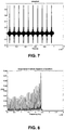
- the pulse train is continued until the spins are tilted 90 degrees. Additionally the spins will try to align themselves with the static magnetic field along the Z-axis. When no further pulses are applied, the spins will align with the z-axis and upon alignment, the signal from the spins will be reduced to zero. After the initially applied pulse train has ended, the further resulting response signal coming from the probes is shown in FIG. 6 .
- the reply of the probes is a pulse train having similar frequency and phase as the initially applied pulse train, and therefore can be referred to as an echo response.
- the characteristics of the excitation pulse train are selected so as to improve or optimize the signal to noise ratio. By increasing the step size between the frequencies the pulse repetition rate can be made faster. This allows putting more power during a shorter period of time into the system. However when increasing the frequency steps, less probes will be activated.
- the signal to noise ratio can be improved or optimized by choosing a good, improved or optimal step size taken into account the relaxation times of the probes.
- the frequency steps also referred to as frequency grating
- the shape of the pulses in the pulse train may be adapted in order to improve or optimize the response of the probes. The latter may be particularly suitable for probes having a broad line width.
- the amplitude and/or phase of each of the individual frequencies excited by the excitation pulse can be modified such that each of the probes, e.g. spins, can generate a good, improved or maximum signal.
- the amplitude, corresponding with the excitation power provided, for a plurality of or for each of the composing frequencies can be separately modified to match with the individual probes.
- FIG. 7 and FIG. 8 illustrate an excitation pulse train and its Fourier Transform for the situation whereby at lower frequencies less power is required to induce a probe spin flip of 90 degrees and at higher frequencies more power is required. It can be seen that by tuning the shape of the pulses in time domain, the corresponding frequency domain excitation provides the appropriate excitation power.
- the excitation pulse train may, alternatively or in addition thereto, also be adapted to compensate effects induced by the transfer function of the antenna used for detecting the echo reply. In one embodiment, optimization can be done by choosing the optimal bandwidth of the pulse train, depending on the line width of the probes to be measured. In one embodiment, the present invention relates to a method and system as described above, wherein furthermore the excitation pulse train is adapted for exploiting correlation between the excitation pulses and the echo response. The number of frequencies, the spacing between the frequencies, the amplitude and the phase of each of the frequencies may be particularly tuned. As the signature of the excitation pulses in the pulse train and the echo pulses in the echo response are the same, the signal to noise ratio can be increased using spread spectrum techniques.
- pulses with different shapes may be used. Any of the frequencies can have a specific amplitude/phase.
- the resulting transmit sequence can be applied to the probes. When correlating the transmitted signal with the received signal coming from the probes, the resulting signal will be maximum for those probes which are excited with the corresponding pulse train. In a multiple antenna setup this could be used to distinguish between the different antennas. Different pulse shapes also can be used to obtain a better space resolution.
- the present invention relates to a system for performing pulsed electron paramagnetic resonance.
- a system for performing pulsed electron paramagnetic resonance.
- Such a system advantageously may be adapted for performing a method as described in more detail above.
- the system 900 typically comprises a static magnetic field generator 902.
- a static magnetic field generator or generating means 902 may be any type of magnetic field generator such as for example a permanent magnet, an electromagnet.
- the system 900 comprises a magnetic excitation pulse train generator or generating means 904, adapted for generating an magnetic excitation pulse train.
- Such a magnetic excitation pulse train generator 904 may be of any suitable means, such as for example an electromagnet antenna.
- the magnetic excitation pulse train generator 904 may be adapted for generating an excitation pulse train so that an echo response is generated by the probes based on positive interference between the responses .
- the magnetic excitation pulse train generator 904 may comprise a controller 906 adapted for controlling the magnetic excitation pulse train generator 904 accordingly.
- a controller 906 may for example be implemented as software run on a processor or as hardware.
- the controller may be a separate component co-operating with the magnetic excitation pulse train generator 904.
- the system 900 furthermore comprises a detection means or detector 908, adapted for detecting an echo response from the object under study. Such a detector 908 may be a receiving antenna.
- the system furthermore may comprise one or more of an object holder 910, such as for example an object table, a scanning system 912 for detecting information in a topological manner, a processor 914 for processing the results obtained with the detector 908 the obtained results, etc.
- object holder 910 such as for example an object table
- scanning system 912 for detecting information in a topological manner
- processor 914 for processing the results obtained with the detector 908 the obtained results
- Other features may be as known in known pulsed electron paramagnetic resonance systems or may be features expressing functionality as described above for the pulsed EPR method.
- an exemplary experiment is discussed illustrating the effect of a pulse train on the EPR response received. It can be seen that a response is obtained which is an effect of the pulse train and which does not occur for single pulses.
- sequence 1 a first sequence
- sequence 2 a following sequency
- FIG. 11a to FIG. 11c illustrates the resulting EPR response obtained.
- FIG. 11a illustrates the background measurement, used for correcting and/or taking into account when evaluating the different measurements
- FIG. 11b illustrates the EPR response using resovist, indicating an extension of the reply with 100ns.
- FIG. 11c illustrates the EPR response using 25nm superparamagnetic particles, resulting in an extension of the reply with 200ns.
- Each of the drawings shows three curves, the full line corresponding with a static magnet field of 0,005 Tesla (50 Gauss), the dashed line corresponding with a static magnet field of 0,009 Tesla (90 Gauss) and the dotted line corresponding with a static magnet field of 0,15 Tesla (1500 Gauss). Furthermore an additional effect is seen after the pulse for these 25nm particles. The effect is less pronounced for higher static magnetic fields.
- embodiments of the present invention also relate to computer-implemented methods for performing pulsed EPR or designing pulsed EPR experiments as indicated above or as can be obtained by the functionality of the system described above.
- Embodiments of the present invention also relate to corresponding computing program products or a controller for controlling a system for performing pulsed EPR or designing pulsed EPR experiments as described above.
- Such methods may be implemented in a computing system, such as for example a general purpose computer.
- the computing system may comprise an input means and a data processor, which may be set up as a single data processor or as a plurality of processors.
- the computing system may include a processor, a memory system including for example ROM or RAM, an output system such as for example a CD-rom or DVD drive or means for outputting information over a network.
- a processor a memory system including for example ROM or RAM
- an output system such as for example a CD-rom or DVD drive or means for outputting information over a network.
- Conventional computer components such as for example a keybord, display, pointing device, input and output ports, etc also may be included.
- Data transport may be provided based on data busses.
- the memory of the computing system may comprise a set of instructions, which, when implemented on the computing system, result in implementation of the standard steps of the method as set out above and optionally of the optional steps as set out above. Therefore, a computing system including instructions for implementing the method for performing or designing pulsed EPR is not part of the prior art.
- inventions of the present invention encompass computer program products embodied in a carrier medium carrying machine readable code for execution on a computing device, the computer program products as such as well as the data carrier such as dvd or cd-rom or memory device. Aspects of embodiments furthermore encompass the transmitting of a computer program product over a network, such as for example a local network or a wide area network, as well as the transmission signals corresponding therewith.
Landscapes
- Physics & Mathematics (AREA)
- General Physics & Mathematics (AREA)
- Biochemistry (AREA)
- Life Sciences & Earth Sciences (AREA)
- Chemical & Material Sciences (AREA)
- Analytical Chemistry (AREA)
- Health & Medical Sciences (AREA)
- General Health & Medical Sciences (AREA)
- High Energy & Nuclear Physics (AREA)
- Immunology (AREA)
- Pathology (AREA)
- Condensed Matter Physics & Semiconductors (AREA)
- Magnetic Resonance Imaging Apparatus (AREA)
Claims (10)
- Verfahren zum Durchführen von gepulster paramagnetischer Elektronenresonanz, wobei das Verfahren umfasst- Erzeugen eines statischen Magnetfeldes für ein Spinsonden umfassendes Objekt, zum Bereitstellen einer anfänglichen Ausrichtung der Spins,- Erzeugen eines Erregungsimpulszuges, wobei der Erregungsimpulszug Erregungsmagnetfeldimpulse umfasst, wobei das entsprechende Magnetfeld derselben eine andere Ausrichtung aufweist als das statische Magnetfeld, und- Erfassen einer vom Erregungsimpulszug induzierten Echoantwort aus den Spinsonden,wobei die Spinsonden Breitbandsonden sind, d. h. zu einer EPR-Linienbreite von 3 MHz oder größer führen, wobei der Erregungsimpulszug vorbestimmte Frequenzen der Spinsonden erregt und positive Interferenzeffekte zwischen Antworten der Sonden induziert, zum Bilden der Echoantwort ohne Anwenden eines Rephasing-Impulses.
- Verfahren nach einem der vorstehenden Ansprüche, wobei das Erfassen der Echoantwort das Abbilden von Echoantworten aus Sonden umfasst, die im Objekt verteilt sind.
- Verfahren nach einem der vorstehenden Ansprüche, wobei das Erfassen der Echoantwort das Erfassen der Echoantwort aus Einzeldomänenteilchen umfasst.
- Verfahren nach Anspruch 3, wobei das Erfassen der Echoantwort das Erfassen der Echoantwort aus superparamagnetischen Breitbandresonanzteilchen umfasst.
- Verfahren nach einem der vorstehenden Ansprüche, wobei das Erzeugen eines Erregungsimpulszuges umfasst
Erzeugen einer EPR-Impulsfolge, wobei die Form von verschiedenen EPR-Impulsen in der EPR-Impulsfolge dafür ausgebildet ist, Frequenzabhängigkeit der Resonanz der Spins der Sonden im Objekt mindestens teilweise zu kompensieren. - Verfahren nach einem der vorstehenden Ansprüche, wobei das Erzeugen eines Erregungsimpulszuges umfasst
Erzeugen einer EPR-Impulsfolge, wobei die Stärke von verschiedenen EPR-Frequenzen in der EPR-Impulsfolge dafür ausgebildet ist, Leistungsabhängigkeit der EPR-Resonanz von Spinsonden im Objekt oder eines Erfassungssystems mindestens teilweise zu kompensieren. - Verfahren nach einem der vorstehenden Ansprüche, wobei das Verfahren das Anwenden einer Folgenkombination umfasst, wobei das Anwenden einer Folgenkombination umfasst
das Erzeugen eines Erregungsimpulszuges, das das Erzeugen einer ersten Folge ist, die einen Impulszug umfasst, für den eine Echoantwort erwartet wird, und
weiter das Erzeugen einer zweiten Folge umfassend, die ein Einzelimpuls ist, nach dem keine Echoantwort erwartet wird, wobei die erste und die zweite Folge verglichen miteinander eine Phasenverschiebung π aufweisen, wobei das Verfahren das Alternieren der ersten Sequenz und der zweiten Sequenz und Mitteln der Daten umfasst, und wobei das Erzeugen der zweiten Folge das Erzeugen einer zweiten Folge nach dem Erfassen einer von der den Impulszug umfassenden ersten Sequenz induzierten Echoantwort aus den Sonden ist. - System (900) zum Durchführen von gepulster paramagnetischer Elektronenresonanz eines Objekts, welches Breitbandspinsonden enthält, die zu EPR-Linienbreiten von 3 MHz oder größer führen, wobei das System umfasst- einen Objekthalter, der das in Untersuchung befindliche Objekt umfasst,- einen statischen Magnetfeldgenerator (902) zum Anwenden eines statischen Magnetfeldes auf das Spinsonden umfassende Objekt, zum Bereitstellen einer anfänglichen Ausrichtung der Spins,- einen Erregungsimpulszuggenerator (904), der eine Steuerung umfasst, die dafür konfiguriert ist, einen Erregungsimpulszug zu erzeugen, der Erregungsmagnetfeldimpuls umfasst, wobei das entsprechende Magnetfeld derselben eine andere Ausrichtung aufweist als das statische Magnetfeld, wobei der Erregungsimpulszug selektiv vorbestimmte Frequenzen der Spinsonden erregt, und positive Interferenzeffekte zwischen Antworten der Sonden induziert, zum Bilden einer Echoantwort ohne der Notwendigkeit eines Rephasing-Impulses, und- Erfassungsmittel (908), die dafür konfiguriert sind, eine vom Erregungsimpulszug induzierte Echoantwort aus den Sonden zu erfassen.
- System (900) nach Anspruch 8, wobei das Erfassungsmittel dafür ausgebildet ist, Echoantworten aus im Objekt verteilten Sonden abzubilden.
- Computerprogrammprodukt zum Durchführen eines Verfahrens nach einem der Ansprüche 1 bis 7, wenn es in einer Steuerung zum Steuern eines Systems nach einem der Ansprüche 8 bis 9 ausgeführt wird.
Priority Applications (1)
| Application Number | Priority Date | Filing Date | Title |
|---|---|---|---|
| EP09744097.8A EP2331982B1 (de) | 2008-09-30 | 2009-09-30 | Gepulste epr-detektion |
Applications Claiming Priority (6)
| Application Number | Priority Date | Filing Date | Title |
|---|---|---|---|
| US10137408P | 2008-09-30 | 2008-09-30 | |
| GBGB0906644.0A GB0906644D0 (en) | 2009-04-17 | 2009-04-17 | Magnetic resonance imaging of single domain nano-particles |
| EP09165120A EP2273280A1 (de) | 2009-07-10 | 2009-07-10 | Gepulste EPR-Detektion |
| US22542409P | 2009-07-14 | 2009-07-14 | |
| PCT/EP2009/062723 WO2010037801A1 (en) | 2008-09-30 | 2009-09-30 | Pulsed epr detection |
| EP09744097.8A EP2331982B1 (de) | 2008-09-30 | 2009-09-30 | Gepulste epr-detektion |
Publications (2)
| Publication Number | Publication Date |
|---|---|
| EP2331982A1 EP2331982A1 (de) | 2011-06-15 |
| EP2331982B1 true EP2331982B1 (de) | 2018-11-14 |
Family
ID=41478806
Family Applications (1)
| Application Number | Title | Priority Date | Filing Date |
|---|---|---|---|
| EP09744097.8A Active EP2331982B1 (de) | 2008-09-30 | 2009-09-30 | Gepulste epr-detektion |
Country Status (4)
| Country | Link |
|---|---|
| US (1) | US8816685B2 (de) |
| EP (1) | EP2331982B1 (de) |
| JP (1) | JP5576869B2 (de) |
| WO (1) | WO2010037801A1 (de) |
Families Citing this family (5)
| Publication number | Priority date | Publication date | Assignee | Title |
|---|---|---|---|---|
| GB0906644D0 (en) * | 2009-04-17 | 2009-06-03 | Imec Inter Uni Micro Electr | Magnetic resonance imaging of single domain nano-particles |
| GB2489403A (en) * | 2011-03-22 | 2012-10-03 | Pepric Nv | Isolating active electron spin signals in EPR by changing field direction |
| PL219169B1 (pl) * | 2011-03-24 | 2015-03-31 | Mikołaj Baranowski | Sposób wyznaczania elektronowych czasów relaksacji T₁ w tomografii EPR |
| GB201217228D0 (en) | 2012-09-26 | 2012-11-07 | Pepric Nv | Methods and systems for determining a particle distribution |
| RU2727551C2 (ru) | 2015-02-09 | 2020-07-22 | Пеприк Нв | Система и способ определения количества магнитных частиц |
Family Cites Families (12)
| Publication number | Priority date | Publication date | Assignee | Title |
|---|---|---|---|---|
| GB8713353D0 (en) | 1987-06-08 | 1987-07-15 | Scient Generics Ltd | Magnetic article surveillance systems |
| US5387867A (en) * | 1993-07-26 | 1995-02-07 | The United States Of America As Represented By The Dept. Of Health And Human Services | Pulsed low frequency EPR spectrometer and imager |
| JP3345527B2 (ja) * | 1995-05-16 | 2002-11-18 | 株式会社日立製作所 | 核磁気共鳴装置 |
| US5678548A (en) * | 1995-07-20 | 1997-10-21 | The United States Of America As Represented By The Department Of Health And Human Services | System and method for performing in vivo imaging and oxymetry and FT microscopy by pulsed radiofrequency electron paramagnetic resonance |
| DE10037883A1 (de) | 2000-08-03 | 2002-02-14 | Henkel Kgaa | Ferromagnetische Resonanzanregung und ihre Verwendung zur Erwärmung teilchengefüllter Substrate |
| US6693426B1 (en) * | 2002-02-09 | 2004-02-17 | Intematix Corporation | Spatially resolved spin resonance detection |
| WO2004030148A1 (ja) | 2002-09-30 | 2004-04-08 | The Furukawa Electric Co., Ltd. | Rfidタグ及びその製造方法 |
| US7289839B2 (en) | 2002-12-30 | 2007-10-30 | Calypso Medical Technologies, Inc. | Implantable marker with a leadless signal transmitter compatible for use in magnetic resonance devices |
| US20050118102A1 (en) * | 2003-04-28 | 2005-06-02 | Intematix Corporation | Spin resonance heating and/or imaging in medical applications |
| JP4810368B2 (ja) * | 2006-09-11 | 2011-11-09 | 株式会社日立製作所 | 電子スピン共鳴ct装置 |
| JP2008212505A (ja) * | 2007-03-07 | 2008-09-18 | Hitachi Ltd | Mri装置 |
| GB0906644D0 (en) * | 2009-04-17 | 2009-06-03 | Imec Inter Uni Micro Electr | Magnetic resonance imaging of single domain nano-particles |
-
2009
- 2009-09-30 EP EP09744097.8A patent/EP2331982B1/de active Active
- 2009-09-30 WO PCT/EP2009/062723 patent/WO2010037801A1/en not_active Ceased
- 2009-09-30 JP JP2011529548A patent/JP5576869B2/ja active Active
-
2011
- 2011-03-29 US US13/075,087 patent/US8816685B2/en active Active
Non-Patent Citations (1)
| Title |
|---|
| None * |
Also Published As
| Publication number | Publication date |
|---|---|
| US8816685B2 (en) | 2014-08-26 |
| JP2012504247A (ja) | 2012-02-16 |
| WO2010037801A9 (en) | 2010-05-27 |
| WO2010037801A1 (en) | 2010-04-08 |
| US20120049847A1 (en) | 2012-03-01 |
| JP5576869B2 (ja) | 2014-08-20 |
| EP2331982A1 (de) | 2011-06-15 |
Similar Documents
| Publication | Publication Date | Title |
|---|---|---|
| US6566873B1 (en) | Method of and apparatus for nuclear quadrupole resonance testing a sample | |
| O’Dell et al. | QCPMG using adiabatic pulses for faster acquisition of ultra-wideline NMR spectra | |
| CN102866371B (zh) | 磁场不敏感的化学交换饱和转移成像 | |
| JPS59107246A (ja) | 局在化nmr化学シフト分光法を実施する方法と装置 | |
| Kartäusch et al. | Spatial phase encoding exploiting the Bloch–Siegert shift effect | |
| EP3060116B1 (de) | Mr-bildgebung mit temperaturkartierung | |
| EP2331982B1 (de) | Gepulste epr-detektion | |
| US9551773B2 (en) | Isolating active electron spin signals in EPR | |
| JP3808601B2 (ja) | 磁気共鳴診断装置 | |
| EP2369987B1 (de) | Quantitative sauerstoffbildgebungsverfahren mittels einzelpunktbildgebung auf echobasis | |
| EP2378281A1 (de) | Verfahren zum Messen Elektronenrelaxation bei T1-EPR-Tomographie und System zur Anwendung des Verfahrens | |
| JP2633259B2 (ja) | 核磁気共鳴技術による固体写像法 | |
| US10768250B2 (en) | Techniques for operating magnetic resonance imagers to crush returns from unwanted coherence pathways | |
| WO2020235505A1 (ja) | 核磁気共鳴イメージング装置、核磁気共鳴イメージング方法、及びプログラム | |
| EP2273280A1 (de) | Gepulste EPR-Detektion | |
| WO1994003823A1 (en) | A single shot magnetic resonance method to measure diffusion, flow and/or motion | |
| JPS614952A (ja) | 被検体の核磁気特性のマツピング装置 | |
| Tseytlin et al. | Decoupling of excitation and receive coils in pulsed magnetic resonance using sinusoidal magnetic field modulation | |
| US20120098537A1 (en) | High Resolution Nuclear Magnet Resonance with Unknown Spatiotemporal Variations of the Static Magnetic Field | |
| JPH04348291A (ja) | 選択的抑制化学シフト情報導出装置 | |
| Cottrell et al. | New capabilities at pulsed muon facilities with pulsed radio-frequency techniques | |
| Seyoum | Pulse sequences for multi-frequency selective NMR excitation in inhomogeneous magnetic fields |
Legal Events
| Date | Code | Title | Description |
|---|---|---|---|
| PUAI | Public reference made under article 153(3) epc to a published international application that has entered the european phase |
Free format text: ORIGINAL CODE: 0009012 |
|
| 17P | Request for examination filed |
Effective date: 20110330 |
|
| AK | Designated contracting states |
Kind code of ref document: A1 Designated state(s): AT BE BG CH CY CZ DE DK EE ES FI FR GB GR HR HU IE IS IT LI LT LU LV MC MK MT NL NO PL PT RO SE SI SK SM TR |
|
| AX | Request for extension of the european patent |
Extension state: AL BA RS |
|
| DAX | Request for extension of the european patent (deleted) | ||
| 17Q | First examination report despatched |
Effective date: 20141211 |
|
| RAP1 | Party data changed (applicant data changed or rights of an application transferred) |
Owner name: PEPRIC Owner name: IMEC |
|
| RAP1 | Party data changed (applicant data changed or rights of an application transferred) |
Owner name: IMEC VZW Owner name: PEPRIC |
|
| GRAP | Despatch of communication of intention to grant a patent |
Free format text: ORIGINAL CODE: EPIDOSNIGR1 |
|
| STAA | Information on the status of an ep patent application or granted ep patent |
Free format text: STATUS: GRANT OF PATENT IS INTENDED |
|
| INTG | Intention to grant announced |
Effective date: 20180529 |
|
| GRAS | Grant fee paid |
Free format text: ORIGINAL CODE: EPIDOSNIGR3 |
|
| GRAA | (expected) grant |
Free format text: ORIGINAL CODE: 0009210 |
|
| STAA | Information on the status of an ep patent application or granted ep patent |
Free format text: STATUS: THE PATENT HAS BEEN GRANTED |
|
| AK | Designated contracting states |
Kind code of ref document: B1 Designated state(s): AT BE BG CH CY CZ DE DK EE ES FI FR GB GR HR HU IE IS IT LI LT LU LV MC MK MT NL NO PL PT RO SE SI SK SM TR |
|
| REG | Reference to a national code |
Ref country code: GB Ref legal event code: FG4D |
|
| REG | Reference to a national code |
Ref country code: CH Ref legal event code: EP Ref country code: AT Ref legal event code: REF Ref document number: 1065471 Country of ref document: AT Kind code of ref document: T Effective date: 20181115 |
|
| REG | Reference to a national code |
Ref country code: IE Ref legal event code: FG4D |
|
| REG | Reference to a national code |
Ref country code: DE Ref legal event code: R096 Ref document number: 602009055647 Country of ref document: DE |
|
| REG | Reference to a national code |
Ref country code: NL Ref legal event code: MP Effective date: 20181114 |
|
| REG | Reference to a national code |
Ref country code: LT Ref legal event code: MG4D |
|
| REG | Reference to a national code |
Ref country code: AT Ref legal event code: MK05 Ref document number: 1065471 Country of ref document: AT Kind code of ref document: T Effective date: 20181114 |
|
| PG25 | Lapsed in a contracting state [announced via postgrant information from national office to epo] |
Ref country code: LV Free format text: LAPSE BECAUSE OF FAILURE TO SUBMIT A TRANSLATION OF THE DESCRIPTION OR TO PAY THE FEE WITHIN THE PRESCRIBED TIME-LIMIT Effective date: 20181114 Ref country code: ES Free format text: LAPSE BECAUSE OF FAILURE TO SUBMIT A TRANSLATION OF THE DESCRIPTION OR TO PAY THE FEE WITHIN THE PRESCRIBED TIME-LIMIT Effective date: 20181114 Ref country code: NO Free format text: LAPSE BECAUSE OF FAILURE TO SUBMIT A TRANSLATION OF THE DESCRIPTION OR TO PAY THE FEE WITHIN THE PRESCRIBED TIME-LIMIT Effective date: 20190214 Ref country code: AT Free format text: LAPSE BECAUSE OF FAILURE TO SUBMIT A TRANSLATION OF THE DESCRIPTION OR TO PAY THE FEE WITHIN THE PRESCRIBED TIME-LIMIT Effective date: 20181114 Ref country code: FI Free format text: LAPSE BECAUSE OF FAILURE TO SUBMIT A TRANSLATION OF THE DESCRIPTION OR TO PAY THE FEE WITHIN THE PRESCRIBED TIME-LIMIT Effective date: 20181114 Ref country code: IS Free format text: LAPSE BECAUSE OF FAILURE TO SUBMIT A TRANSLATION OF THE DESCRIPTION OR TO PAY THE FEE WITHIN THE PRESCRIBED TIME-LIMIT Effective date: 20190314 Ref country code: BG Free format text: LAPSE BECAUSE OF FAILURE TO SUBMIT A TRANSLATION OF THE DESCRIPTION OR TO PAY THE FEE WITHIN THE PRESCRIBED TIME-LIMIT Effective date: 20190214 Ref country code: LT Free format text: LAPSE BECAUSE OF FAILURE TO SUBMIT A TRANSLATION OF THE DESCRIPTION OR TO PAY THE FEE WITHIN THE PRESCRIBED TIME-LIMIT Effective date: 20181114 Ref country code: HR Free format text: LAPSE BECAUSE OF FAILURE TO SUBMIT A TRANSLATION OF THE DESCRIPTION OR TO PAY THE FEE WITHIN THE PRESCRIBED TIME-LIMIT Effective date: 20181114 |
|
| PG25 | Lapsed in a contracting state [announced via postgrant information from national office to epo] |
Ref country code: GR Free format text: LAPSE BECAUSE OF FAILURE TO SUBMIT A TRANSLATION OF THE DESCRIPTION OR TO PAY THE FEE WITHIN THE PRESCRIBED TIME-LIMIT Effective date: 20190215 Ref country code: SE Free format text: LAPSE BECAUSE OF FAILURE TO SUBMIT A TRANSLATION OF THE DESCRIPTION OR TO PAY THE FEE WITHIN THE PRESCRIBED TIME-LIMIT Effective date: 20181114 Ref country code: NL Free format text: LAPSE BECAUSE OF FAILURE TO SUBMIT A TRANSLATION OF THE DESCRIPTION OR TO PAY THE FEE WITHIN THE PRESCRIBED TIME-LIMIT Effective date: 20181114 Ref country code: PT Free format text: LAPSE BECAUSE OF FAILURE TO SUBMIT A TRANSLATION OF THE DESCRIPTION OR TO PAY THE FEE WITHIN THE PRESCRIBED TIME-LIMIT Effective date: 20190314 |
|
| PG25 | Lapsed in a contracting state [announced via postgrant information from national office to epo] |
Ref country code: DK Free format text: LAPSE BECAUSE OF FAILURE TO SUBMIT A TRANSLATION OF THE DESCRIPTION OR TO PAY THE FEE WITHIN THE PRESCRIBED TIME-LIMIT Effective date: 20181114 Ref country code: PL Free format text: LAPSE BECAUSE OF FAILURE TO SUBMIT A TRANSLATION OF THE DESCRIPTION OR TO PAY THE FEE WITHIN THE PRESCRIBED TIME-LIMIT Effective date: 20181114 Ref country code: IT Free format text: LAPSE BECAUSE OF FAILURE TO SUBMIT A TRANSLATION OF THE DESCRIPTION OR TO PAY THE FEE WITHIN THE PRESCRIBED TIME-LIMIT Effective date: 20181114 Ref country code: CZ Free format text: LAPSE BECAUSE OF FAILURE TO SUBMIT A TRANSLATION OF THE DESCRIPTION OR TO PAY THE FEE WITHIN THE PRESCRIBED TIME-LIMIT Effective date: 20181114 |
|
| REG | Reference to a national code |
Ref country code: DE Ref legal event code: R097 Ref document number: 602009055647 Country of ref document: DE |
|
| PG25 | Lapsed in a contracting state [announced via postgrant information from national office to epo] |
Ref country code: RO Free format text: LAPSE BECAUSE OF FAILURE TO SUBMIT A TRANSLATION OF THE DESCRIPTION OR TO PAY THE FEE WITHIN THE PRESCRIBED TIME-LIMIT Effective date: 20181114 Ref country code: SM Free format text: LAPSE BECAUSE OF FAILURE TO SUBMIT A TRANSLATION OF THE DESCRIPTION OR TO PAY THE FEE WITHIN THE PRESCRIBED TIME-LIMIT Effective date: 20181114 Ref country code: EE Free format text: LAPSE BECAUSE OF FAILURE TO SUBMIT A TRANSLATION OF THE DESCRIPTION OR TO PAY THE FEE WITHIN THE PRESCRIBED TIME-LIMIT Effective date: 20181114 Ref country code: SK Free format text: LAPSE BECAUSE OF FAILURE TO SUBMIT A TRANSLATION OF THE DESCRIPTION OR TO PAY THE FEE WITHIN THE PRESCRIBED TIME-LIMIT Effective date: 20181114 |
|
| PLBE | No opposition filed within time limit |
Free format text: ORIGINAL CODE: 0009261 |
|
| STAA | Information on the status of an ep patent application or granted ep patent |
Free format text: STATUS: NO OPPOSITION FILED WITHIN TIME LIMIT |
|
| 26N | No opposition filed |
Effective date: 20190815 |
|
| PG25 | Lapsed in a contracting state [announced via postgrant information from national office to epo] |
Ref country code: SI Free format text: LAPSE BECAUSE OF FAILURE TO SUBMIT A TRANSLATION OF THE DESCRIPTION OR TO PAY THE FEE WITHIN THE PRESCRIBED TIME-LIMIT Effective date: 20181114 |
|
| PG25 | Lapsed in a contracting state [announced via postgrant information from national office to epo] |
Ref country code: TR Free format text: LAPSE BECAUSE OF FAILURE TO SUBMIT A TRANSLATION OF THE DESCRIPTION OR TO PAY THE FEE WITHIN THE PRESCRIBED TIME-LIMIT Effective date: 20181114 |
|
| PG25 | Lapsed in a contracting state [announced via postgrant information from national office to epo] |
Ref country code: MC Free format text: LAPSE BECAUSE OF FAILURE TO SUBMIT A TRANSLATION OF THE DESCRIPTION OR TO PAY THE FEE WITHIN THE PRESCRIBED TIME-LIMIT Effective date: 20181114 |
|
| REG | Reference to a national code |
Ref country code: CH Ref legal event code: PL |
|
| PG25 | Lapsed in a contracting state [announced via postgrant information from national office to epo] |
Ref country code: LI Free format text: LAPSE BECAUSE OF NON-PAYMENT OF DUE FEES Effective date: 20190930 Ref country code: IE Free format text: LAPSE BECAUSE OF NON-PAYMENT OF DUE FEES Effective date: 20190930 Ref country code: LU Free format text: LAPSE BECAUSE OF NON-PAYMENT OF DUE FEES Effective date: 20190930 Ref country code: CH Free format text: LAPSE BECAUSE OF NON-PAYMENT OF DUE FEES Effective date: 20190930 |
|
| REG | Reference to a national code |
Ref country code: BE Ref legal event code: MM Effective date: 20190930 |
|
| PG25 | Lapsed in a contracting state [announced via postgrant information from national office to epo] |
Ref country code: BE Free format text: LAPSE BECAUSE OF NON-PAYMENT OF DUE FEES Effective date: 20190930 |
|
| PG25 | Lapsed in a contracting state [announced via postgrant information from national office to epo] |
Ref country code: CY Free format text: LAPSE BECAUSE OF FAILURE TO SUBMIT A TRANSLATION OF THE DESCRIPTION OR TO PAY THE FEE WITHIN THE PRESCRIBED TIME-LIMIT Effective date: 20181114 |
|
| PG25 | Lapsed in a contracting state [announced via postgrant information from national office to epo] |
Ref country code: MT Free format text: LAPSE BECAUSE OF FAILURE TO SUBMIT A TRANSLATION OF THE DESCRIPTION OR TO PAY THE FEE WITHIN THE PRESCRIBED TIME-LIMIT Effective date: 20181114 Ref country code: HU Free format text: LAPSE BECAUSE OF FAILURE TO SUBMIT A TRANSLATION OF THE DESCRIPTION OR TO PAY THE FEE WITHIN THE PRESCRIBED TIME-LIMIT; INVALID AB INITIO Effective date: 20090930 |
|
| PG25 | Lapsed in a contracting state [announced via postgrant information from national office to epo] |
Ref country code: MK Free format text: LAPSE BECAUSE OF FAILURE TO SUBMIT A TRANSLATION OF THE DESCRIPTION OR TO PAY THE FEE WITHIN THE PRESCRIBED TIME-LIMIT Effective date: 20181114 |
|
| P01 | Opt-out of the competence of the unified patent court (upc) registered |
Effective date: 20230513 |
|
| PGFP | Annual fee paid to national office [announced via postgrant information from national office to epo] |
Ref country code: DE Payment date: 20250820 Year of fee payment: 17 |
|
| PGFP | Annual fee paid to national office [announced via postgrant information from national office to epo] |
Ref country code: GB Payment date: 20250820 Year of fee payment: 17 |
|
| PGFP | Annual fee paid to national office [announced via postgrant information from national office to epo] |
Ref country code: FR Payment date: 20250820 Year of fee payment: 17 |