EP2332658B1 - Hochspannungssteuerung mit verbesserter Überwachung und Diagnostik - Google Patents
Hochspannungssteuerung mit verbesserter Überwachung und Diagnostik Download PDFInfo
- Publication number
- EP2332658B1 EP2332658B1 EP10015399.8A EP10015399A EP2332658B1 EP 2332658 B1 EP2332658 B1 EP 2332658B1 EP 10015399 A EP10015399 A EP 10015399A EP 2332658 B1 EP2332658 B1 EP 2332658B1
- Authority
- EP
- European Patent Office
- Prior art keywords
- voltage
- current
- high voltage
- input
- controller
- Prior art date
- Legal status (The legal status is an assumption and is not a legal conclusion. Google has not performed a legal analysis and makes no representation as to the accuracy of the status listed.)
- Active
Links
Images




Classifications
-
- H—ELECTRICITY
- H02—GENERATION; CONVERSION OR DISTRIBUTION OF ELECTRIC POWER
- H02M—APPARATUS FOR CONVERSION BETWEEN AC AND AC, BETWEEN AC AND DC, OR BETWEEN DC AND DC, AND FOR USE WITH MAINS OR SIMILAR POWER SUPPLY SYSTEMS; CONVERSION OF DC OR AC INPUT POWER INTO SURGE OUTPUT POWER; CONTROL OR REGULATION THEREOF
- H02M7/00—Conversion of AC power input into DC power output; Conversion of DC power input into AC power output
- H02M7/42—Conversion of DC power input into AC power output without possibility of reversal
- H02M7/44—Conversion of DC power input into AC power output without possibility of reversal by static converters
- H02M7/48—Conversion of DC power input into AC power output without possibility of reversal by static converters using discharge tubes with control electrode or semiconductor devices with control electrode
- H02M7/53—Conversion of DC power input into AC power output without possibility of reversal by static converters using discharge tubes with control electrode or semiconductor devices with control electrode using devices of a triode or transistor type requiring continuous application of a control signal
- H02M7/537—Conversion of DC power input into AC power output without possibility of reversal by static converters using discharge tubes with control electrode or semiconductor devices with control electrode using devices of a triode or transistor type requiring continuous application of a control signal using semiconductor devices only, e.g. single switched pulse inverters
- H02M7/538—Conversion of DC power input into AC power output without possibility of reversal by static converters using discharge tubes with control electrode or semiconductor devices with control electrode using devices of a triode or transistor type requiring continuous application of a control signal using semiconductor devices only, e.g. single switched pulse inverters in a push-pull configuration
- H02M7/53803—Conversion of DC power input into AC power output without possibility of reversal by static converters using discharge tubes with control electrode or semiconductor devices with control electrode using devices of a triode or transistor type requiring continuous application of a control signal using semiconductor devices only, e.g. single switched pulse inverters in a push-pull configuration with automatic control of output voltage or current
- H02M7/53806—Conversion of DC power input into AC power output without possibility of reversal by static converters using discharge tubes with control electrode or semiconductor devices with control electrode using devices of a triode or transistor type requiring continuous application of a control signal using semiconductor devices only, e.g. single switched pulse inverters in a push-pull configuration with automatic control of output voltage or current in a push-pull configuration of the parallel type
-
- G—PHYSICS
- G05—CONTROLLING; REGULATING
- G05F—SYSTEMS FOR REGULATING ELECTRIC OR MAGNETIC VARIABLES
- G05F1/00—Automatic systems in which deviations of an electric quantity from one or more predetermined values are detected at the output of the system and fed back to a device within the system to restore the detected quantity to its predetermined value or values, i.e. retroactive systems
- G05F1/66—Regulating electric power
-
- G—PHYSICS
- G06—COMPUTING OR CALCULATING; COUNTING
- G06G—ANALOGUE COMPUTERS
- G06G7/00—Devices in which the computing operation is performed by varying electric or magnetic quantities
- G06G7/48—Analogue computers for specific processes, systems or devices, e.g. simulators
- G06G7/66—Analogue computers for specific processes, systems or devices, e.g. simulators for control systems
-
- H—ELECTRICITY
- H02—GENERATION; CONVERSION OR DISTRIBUTION OF ELECTRIC POWER
- H02M—APPARATUS FOR CONVERSION BETWEEN AC AND AC, BETWEEN AC AND DC, OR BETWEEN DC AND DC, AND FOR USE WITH MAINS OR SIMILAR POWER SUPPLY SYSTEMS; CONVERSION OF DC OR AC INPUT POWER INTO SURGE OUTPUT POWER; CONTROL OR REGULATION THEREOF
- H02M3/00—Conversion of DC power input into DC power output
- H02M3/22—Conversion of DC power input into DC power output with intermediate conversion into AC
- H02M3/24—Conversion of DC power input into DC power output with intermediate conversion into AC by static converters
- H02M3/28—Conversion of DC power input into DC power output with intermediate conversion into AC by static converters using discharge tubes with control electrode or semiconductor devices with control electrode to produce the intermediate AC
- H02M3/325—Conversion of DC power input into DC power output with intermediate conversion into AC by static converters using discharge tubes with control electrode or semiconductor devices with control electrode to produce the intermediate AC using devices of a triode or a transistor type requiring continuous application of a control signal
- H02M3/335—Conversion of DC power input into DC power output with intermediate conversion into AC by static converters using discharge tubes with control electrode or semiconductor devices with control electrode to produce the intermediate AC using devices of a triode or a transistor type requiring continuous application of a control signal using semiconductor devices only
- H02M3/337—Conversion of DC power input into DC power output with intermediate conversion into AC by static converters using discharge tubes with control electrode or semiconductor devices with control electrode to produce the intermediate AC using devices of a triode or a transistor type requiring continuous application of a control signal using semiconductor devices only in push-pull configuration
-
- H—ELECTRICITY
- H03—ELECTRONIC CIRCUITRY
- H03K—PULSE TECHNIQUE
- H03K7/00—Modulating pulses with a continuously-variable modulating signal
- H03K7/08—Duration or width modulation ; Duty cycle modulation
-
- B—PERFORMING OPERATIONS; TRANSPORTING
- B05—SPRAYING OR ATOMISING IN GENERAL; APPLYING FLUENT MATERIALS TO SURFACES, IN GENERAL
- B05B—SPRAYING APPARATUS; ATOMISING APPARATUS; NOZZLES
- B05B5/00—Electrostatic spraying apparatus; Spraying apparatus with means for charging the spray electrically; Apparatus for spraying liquids or other fluent materials by other electric means
- B05B5/08—Plant for applying liquids or other fluent materials to objects
- B05B5/10—Arrangements for supplying power, e.g. charging power
-
- H—ELECTRICITY
- H02—GENERATION; CONVERSION OR DISTRIBUTION OF ELECTRIC POWER
- H02M—APPARATUS FOR CONVERSION BETWEEN AC AND AC, BETWEEN AC AND DC, OR BETWEEN DC AND DC, AND FOR USE WITH MAINS OR SIMILAR POWER SUPPLY SYSTEMS; CONVERSION OF DC OR AC INPUT POWER INTO SURGE OUTPUT POWER; CONTROL OR REGULATION THEREOF
- H02M3/00—Conversion of DC power input into DC power output
- H02M3/01—Resonant DC/DC converters
Definitions
- This application is related to high voltage control systems. More particularly, this application is related to high voltage control systems for use in connection with electrostatic applications including spray systems and filtration systems.
- Typical electrostatic spray systems utilize a high voltage power supply to electrically charge a coating material (e.g., powder or paint). Charged atomized particles are discharged from the electrostatic spray gun and are directed towards an oppositely charged object to be painted. The paint is then attracted to the object yielding an even coat with an increased percentage of coating material that actually sticks to the object.
- a coating material e.g., powder or paint
- An electrostatic spray system typically includes one or more high voltage generators with associated control electronics.
- the high voltage generator is located inside a spray booth and the control electronics are located outside of the spray booth.
- the high voltage generator may be located in the spray gun.
- the controller is typically located outside of the gun due to the size and complexity of control electronics.
- the controller typically provides control signaling for the high voltage generator. Such signaling may be used to set the working parameters of the high voltage generator and may also provide safety controls.
- Document US 2001/0020653 A1 discloses a high voltage controller having a voltage regulator.
- a high voltage control block compares a signal of a storage capacitor and current limiter to an internally set reference voltage. Depending upon the value of the feedback signal the high voltage control block controls a DC/DC converter, e. g. by pulse width modulation.
- Document US 6 370 039 B1 discloses a high voltage controller having an internal feedback loop.
- the output voltage of a transformer is reflected in a primary current which is sensed through a sense resistor.
- a differential amplifier compares the voltage on the sense resistor to a reference voltage proportional to the maximum expected voltage loss at the load as estimated by a user.
- control electronics it would be desirable reduce the size of the control electronics so that they may be collocated in the spray gun along with the high voltage generator. It would also be desirable to provide enhanced control and diagnostics of the high voltage system.
- the object of the invention is solved by a high voltage controller according to claim 1 and a method according to claim 13.
- a high voltage controller configured to drive a high voltage generator.
- the high voltage controller includes a voltage select input and a current select input, an actual voltage input and an actual current input.
- First circuitry is configured to generate an alternating current (AC) drive signal.
- Second circuitry configured to generate a direct current (DC) drive signal.
- Closed loop control circuitry is configured to adjust the DC drive signal based on at least one of the voltage select and current select inputs and at least one of the actual voltage and actual current inputs.
- the first circuitry includes a push-pull circuit.
- the second circuitry includes a pulse width modulation (PWM) controller.
- a high voltage generator may be coupled to the AC and DC drive signals.
- the high voltage generator may include a high voltage transformer having a pair of primary windings and center tap.
- the AC drive signal may be coupled to the primary windings and the DC drive signal may be coupled to the center tap.
- the high voltage controller may include soft start circuitry coupled to at least one input of the PWM controller.
- Safe shutdown circuitry may be coupled to an on/off input.
- the safe shutdown circuitry may be configured to de-energize at least one power supply pin of the PWM controller based on the on/off input.
- the high voltage controller may include a diagnostic mode select input and a plurality switches. Each switch may be configured to select a diagnostic input signal based on the diagnostic mode select input.
- the high voltage controller may also include at least one temperature sensor coupled to over temperature alarm circuitry. Over voltage and over current alarm circuitry may also be provided.
- a rectangular signal generator may be provided to generate an output signal having an output frequency that is mapped to a maximum current capability of the high voltage generator.
- the high voltage controller may include a microcontroller.
- the microcontroller may be configured to generate the DC drive signal.
- the microcontroller may be configured to provide closed loop control and adjust the DC drive signal based on at least one of the voltage select and current select inputs and at least one of the actual voltage and actual current inputs.
- the microcontroller may be configured to adjust at least one of an output frequency and a duty cycle of the AC drive circuitry (e.g., push-pull circuit) based on the actual current input.
- the high voltage controller may include a serial interface configured to connect with an external computer.
- the serial interface may be configured to operate under at least on of a CAN, PROFIBUS or SERCOSIII protocol.
- the microcontroller may be configured to limit a slope of the DC drive signal based on a predefined threshold and the actual voltage input.
- the microcontroller may also be configured to limit a slope of the DC drive signal based on a predefined threshold and the actual current input.
- the microcontroller may be configured to provide at least one of a voltage controlled mode, current controlled mode or a combined voltage and current controlled mode based on at least one of the voltage select input or the current select input.
- FIG. 1 is a basic block diagram of a high voltage spraying system 10. It is understood that various components of this system may be used in other electrostatic applications including air filtration systems and the like.
- the high voltage spraying system includes a main computer 20 coupled to one or more high voltage controllers 30. Each high voltage controller 30 is coupled to a high voltage generator 40. The output of the high voltage generator 40 is coupled to one or more charging electrodes 50 (e.g., corona electrodes).
- charging electrodes 50 e.g., corona electrodes
- a charging electrode 50 may be disposed in an electrostatic spray gun. Such guns are used to apply protective coatings to a wide variety of industrial and commercial products. Typically, a finely divided powder is transported through a spray head while entrained in a fluid stream (e.g., air or gas). The fluidized stream comes into contact with an electrostatic field generated by the charging electrode 50. This imparts a charge to the particles in the fluidized stream. The charged fluidized stream is then discharged from the spray head towards an object to be coated. It is also understood that the charging electrode 50 may form part of an electrostatic filtration system or other electrostatic based equipment.
- a fluid stream e.g., air or gas
- FIG. 2 is a block diagram of an embodiment of an electrostatic spray gun 60.
- the spay gun 60 has a connection to a supply of coating material(s) shown generally by block 64. It is understood that various feed equipment may be used to supply the spray gun 60 with suitable coating materials.
- the spray gun 60 also has various pneumatic connections shown generally by block 66. It is also understood that various pneumatic equipment may be used to supply the spray gun with a suitable supply of air or gas for use in the spraying process.
- the spray gun 60 has a charging electrode 52 (e.g., corona wire) coupled to the output of high voltage generator 42. The charging electrode is generally disposed in a flow path such that a charged fluidized stream is discharged from the spray gun outlet 62.
- a charging electrode 52 e.g., corona wire
- the high voltage controller 32 and the high voltage generator are both located within the spray gun 60.
- the main computer 20 is coupled to the high voltage controller 32 via one or more communication lines represented by line 22.
- the connection between the high voltage controller 32 and the main computer 20 may be implemented with analog and/or digital circuitry as discussed in detail below.
- the high voltage controller 32 is coupled to the high voltage generator via a plurality of lines represented by line 34. These connections are also discussed in detail below.
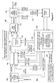
- FIG 3 is a block diagram of an embodiment of a high voltage controller 32a and high voltage generator 42a.
- the high voltage controller 32a provides voltage and current control of the high voltage generator 42a.
- the high voltage generator includes a high voltage transformer 202 and a voltage multiplier 204.
- the voltage multiplier 204 is implemented via a capacitor-diode network or cascade. It is understood that a variety of voltage multipliers configurations may be used.
- the output of the voltage multiplier 206 drives one or more charging electrodes (not shown).
- the high voltage controller 32a has power inputs shown generally by input lines 102 and 104.
- the power for the high voltage transformer 202 is provided via input protection and buffering circuitry as shown by block 106.
- Power for the high voltage controller circuitry is provided via input protection and DC/DC converter circuitry as shown by block 108. It is understood that a variety of power configurations may be used.
- the high voltage controller 32a provides voltage and current control of the high voltage generator 42a. This is accomplished via a pulse width modulation (PWM) controller and closed loop control circuitry. This functionality is shown generally by block 142.
- PWM pulse width modulation
- the output of the PWM controller is coupled to drive circuitry 148 which ultimately drives the high voltage transformer via center tap 214.
- Such circuitry may be implemented in analog and/or digital circuitry as discussed in more detail below.
- Voltage select input 126 and current select input 128 provide selected values for the voltage and current at the output of the high voltage generator 42a. Based on the voltage select input and current select input values, the high voltage controller 32a may operate in one of three modes: 1) voltage controlled mode, 2) current controlled mode or 3) combined voltage and current controlled mode.
- the maximum output voltage is 120,000 volts (120 kV).
- the high voltage generator 42a will produce 120 kV at output 206 when the voltage select input 126 is set to 16 ma. If the voltage select input 126 is set to 4ma, the high voltage generator 42a will produce 0 volts.
- Feedback control is provided by using voltage and current feedback signals generated at the output of the high voltage generator 42a.
- the PWM controller 142 uses the feedback signals to monitor the high voltage output and load current and provide automatic closed loop control.
- the actual load current is represented by line 216.
- the output voltage is redundantly sampled.
- Actual output voltage 1 is represented by line 218, actual output voltage 2 is represented by line 220.
- These feedback signals are clipped and amplified so that they may be input into the PWM controller 142 as shown by blocks 222, 224 and 226.
- the high voltage controller 32a also includes several safety features including soft start control circuitry 144. This circuitry provides a gradual increase in voltage at the output 206 of the high voltage generator 42a. Safe shutdown circuitry is also provided as shown by block 146. This circuitry provides immediate power down of the critical system components so that the high voltage generator is de-energized quickly upon a power off signal. These aspects are discussed in more detail below.
- Figure 5 provides some additional detail on the output steering operation of the PWM controller142.
- the PWM controller will work as a push-pull circuit.
- pin 13 is connected to ground and the PWM controller 142 functions as a single ended or parallel output.
- Q1 and Q2 are coupled to drive circuitry 148 which outputs a DC voltage 350 that drives the center tap of the high voltage transformer 202 and ultimately generates a corresponding high voltage output 206 at the output of the cascade network 204.
- the current select input 320 is below the actual current value 316, an error signal is produced by error amplifier 1 (304) and the output of Q1 and Q2 cause an increased voltage at the output 350 of the drive circuitry 148.
- the voltage select input 322 is below the actual voltage value 318, an error signal is produced by error amplifier 2 (306) and the output a Q1 and Q2 cause an increased voltage at the output 350 of the drive circuitry 148.
- FIG. 6 is a block diagram with additional detail of the push pull control circuit 150 and the MOSFET switches 152.
- This circuit may also be implemented using a TL494 integrated circuit. It is understood that a variety of PWM controllers may be used. Pin 13 of the PWM controller 400 is connected to the output Vref (pin14). This configures the PWM controller to operate as a push-pull circuit.
- the push pull circuit is set for an operating frequency of 25kHz.
- MOSFET switches Q22 and Q23 produce symmetrical pulsed outputs 410 and 412 that drive the legs 210 and 212 of high voltage transformer 202. Because the two primary windings of the high voltage transformer are oppositely wrapped, the output of high voltage transformer is an AC voltage.
- Yet another diagnostic test includes testing the function of all analogue circuits and the fixed threshold values.
- the main computer may compare the current select input 126 and voltage select input 128 with the actual values of load current 242 and output voltage 240. If these values deviate by more than a preselected threshold (e.g., ⁇ 5%), there is failure in the circuit. If no error message is generated by the main computer during the diagnostic mode the high voltage system may go to normal mode.
- a preselected threshold e.g., ⁇ 5%
- On/Off input 120 is routed to R106 via clipping circuit 130.
- On/Off input 120 is in the on state, Q10 and Q11 are conducting and the Vcc pin 143 receives power.
- On/Off input 120 transitions to the off state Q10 and Q11 stop conducting and the Vcc pin 143 is immediately de-energized. This minimizes the time delay associated with a power down signal.
- the high voltage controller 32b is supplied with power via a 110-240VAC supply via a Power Factor Correction (PFC) controller 600.
- PFC controllers are available from a variety of sources including Fairchild Semiconductor of Portland Maine, Infineon technologies AG of Kunststoff, Germany and various other manufacturers.
- the high voltage controller 32b is implemented with redundant microcontrollers shown by block 602.
- Suitable microcontrollers may include on or more embedded analog to digital converters (ADC), one or more embedded digital to analog converters (DAC) and a PWM output.
- ADC analog to digital converters
- DAC embedded digital to analog converters
- PWM output PWM output
- Such microcontrollers are available from a variety of sources including Intel Corporation of Santa Clara, California, PIC Microcontroller, Microchip or Atmel Microcontroller. It is also understood that suitable microcontrollers typically include program memory such as Electrically Erasable Programmable Read Only Memory (EEPROM) and Random Access Memory (RAM).
- EEPROM Electrically Erasable Programmable Read
- FIG 11 is a microcontroller based embodiment of a high voltage controller with resonant frequency control.
- the high voltage controller 32c is supplied with power via a 110-240VAC supply via a Power Factor Correction (PFC) controller 600 as discussed above.
- the high voltage controller 32c is implemented with redundant microcontrollers shown by block 603. Suitable microcontrollers may include on or more embedded analog to digital converters (ADC), one or more embedded digital to analog converters (DAC) and a PWM output as discussed above.
- ADC embedded analog to digital converters
- DAC embedded digital to analog converters
- Microcontroller 603 generates PWM signals 653 to control the duty cycle and frequency of the push-pull circuit 651.
- the high voltage multiplier 704 is a capacitive load that is coupled to the inductance of the secondary winding of high voltage transformer 702. This forms an LC circuit with a certain resonance frequency at which the current consumption is a minimum.
- Each high voltage generator type may have a different resonance frequency due to differences in materials, the number of windings, number of stages of the voltage multiplier, capacitor values and the like.
- the push-pull control circuit 651 is fine tuned for duty cycle and frequency by adjusting PWM output based the actual load current 716.
- An initial push-pull frequency is selected, for example 40kHz as shown by block 902.
- a snapshot of the actual value of the load current is at least temporarily stored in memory as shown by block 904.
- the microcontroller will then determine whether an increase or decrease in push-pull output frequency results in a reduction of load current as shown by block 906. This may be accomplished by lowering the output frequency and comparing a snapshot of the actual value of the load current to the value obtained at block 904. If the load current does not decrease, the process may then be repeated with an increased output frequency.
- a snapshot of the actual value of the load current is compared to the value obtained at block 904. Once the desired direction is obtained the output frequency is adjusted by a suitable increment (e.g., 1kHz) as shown by block 908.
- Figure 13 is a basic flow diagram with a similar technique for establishing the optimal push-pull duty cycle based on actual load current.
- An initial push-pull output duty cycle is selected, for example 50% as shown by block 922.
- a snapshot of the actual value of the load current is at least temporarily stored in memory as shown by block 924.
- the microcontroller will then determine whether an increase or decrease in push-pull duty cycle results in a reduction of load current as shown by block 926. This may be accomplished by lowering the duty cycle and comparing a snapshot of the actual value of the load current to the value obtained at block 924. If the load current does not decrease, the process may then be repeated with an increased duty cycle.
- a snapshot of the actual value of the load current is compared to the value obtained at block 924.
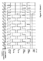
- the outputs Q and /Q of the flip-flop are logically AND linked with the input pin 13. These signals are NOR linked with the output signal of the OR gate to control the Q1 and Q2 (see timing diagram).
- the microcontroller based embodiments disclosed above may implement several functions that are not present in the analog embodiment.
- the microcontroller may limit the slope of the output voltage and/or load current.
- the microcontroller receives and stores digital representations of the voltage and/or current select inputs via the serial bus.
- the microcontroller also receives and stores digital representations of the actual values of output voltage and load current. These values are ultimately used by the microcontroller to drive the high voltage generator as described in Figure 14 .
- the microcontroller also contains embedded timing capabilities.
- the microcontroller may control the rate at which the voltage (i.e., PWM duty cycle) is increased or decreased.
- the microcontroller may store a maximum slope for output voltage and/or load current increase or decrease.
- the microcontroller may temporarily adjust the values provided to the drive circuitry (i.e., temporarily override the voltage select and/or current select inputs) so as to not exceed the maximum slope for output voltage and/or load current increase or decrease.
- This functionality may also be used to implement soft start control.
- the microcontroller may also implement advanced diagnostic functions.
- diagnostic mode is initiated via diagnostic mode select 122. See Figures 3 and 7 .
- a plurality of switches are activated and simulated values are substituted for the voltage and current select inputs as well as the actual values.
- the main computer may also perform diagnostics with the high voltage controller operating in normal mode. For example the main computer may systematically change the voltage and current select inputs and compare the expected output values for voltage and current to the actual values.
- the microcontroller may perform these functions directly and report the results to the main computer via a status message or the like.
- ROM read only memory
- RAM random access memory
- register cache memory
- semiconductor memory devices magnetic media such as internal hard disks and removable disks, magneto-optical media, and optical media such as CD-ROM disks, and digital versatile disks (DVDs).
Landscapes
- Engineering & Computer Science (AREA)
- Power Engineering (AREA)
- Physics & Mathematics (AREA)
- General Physics & Mathematics (AREA)
- Automation & Control Theory (AREA)
- Computer Hardware Design (AREA)
- Theoretical Computer Science (AREA)
- Electromagnetism (AREA)
- Radar, Positioning & Navigation (AREA)
- Mathematical Physics (AREA)
- Dc-Dc Converters (AREA)
Claims (15)
- Hochspannungs-Controller (32, 32a), der einen Hochspannungsgenerator (42a) ansteuert, umfassend:a) einen Spannungsauswahleingang (126, 322) zum Festlegen einer gewünschten Ausgangsspannung, undb) einen Stromauswahleingang (128, 320) zum Festlegen eines gewünschten Laststroms,c) einem Ist-Spannungseingang (318) undd) einem Ist-Stromeingang (316),e) eine erste Schaltung (150), die konfiguriert ist, um ein Wechselstromsteuersignal zu erzeugen,f) eine zweite Schaltung (148), die konfiguriert ist, um ein Gleichstromsteuersignal zu erzeugen, undg) eine Rückkopplungsregelschaltung (142), die konfiguriert ist, um das Gleichstromsteuersignal einzustellen auf der Grundlage des Spannungsauswahl- und/oder des Stromauswahleingangs und des Ist-Spannungs- und/oder des Ist-Stromeingangs,
dadurch gekennzeichnet, dassh) der Hochspannungs-Controller (32, 32a) in Abhängigkeit von dem Spannungsauswahleingang (126, 322) und dem Stromauswahleingang (128, 320) in einer der drei folgenden Betriebsarten arbeiten kann:h1) einer spannungsgesteuerten Betriebsart,h2) einer stromgesteuerten Betriebsart undh3) einer kombiniert spannungs- und stromgesteuerten Betriebsart,i) der Stromauswahleingang (128, 320) in der spannungsgesteuerten Betriebsart auf dem gewünschten Laststrom festgesetzt wird und der Hochspannungs-Controller (32, 32a) die Ausgangsspannung des Hochspannungsgenerators (42a) variiert, sodass der gewünschte Laststrom beibehalten wird,j) der Spannungsauswahleingang (126, 322) in der stromgesteuerten Betriebsart auf die gewünschte Ausgangsspannung festgesetzt wird und der Hochspannungs-Controller (32, 32a) die Ausgangsspannung des Hochspannungsgenerators (42a) variiert, sodass die gewünschte Ausgangsspannung an der Last beibehalten wird, undk) der Spannungsauswahleingang (126, 322) und der Stromauswahleingang (128, 320) in der kombiniert spannungs- und stromgesteuerten Betriebsart auf die gewünschten Werte festgesetzt werden und der Hochspannungs-Controller (32, 32a) die Ausgangsspannung des Hochspannungsgenerators (42a) variiert, sodass mindestens einer der Sollwerte von ausgewählter Spannung und Strom an der Last beibehalten werden. - Hochspannungs-Controller (32, 32a) gemäß Anspruch 1, wobei die erste Schaltung (150) eine Push-Pull-Schaltung (152, 651) aufweist.
- Hochspannungs-Controller (32, 32a) gemäß Anspruch 2, weiterhin umfassend:Einen Mikrocontroller (603) der konfiguriert ist, um eine Ausgangsfrequenz und/oder einen Betriebszyklus der Push-Pull-Schaltung (651) basierend auf dem Ist-Stromeingang einzustellen.
- Hochspannungs-Controller (32, 32a) gemäß Anspruch 3, weiterhin umfassend:Mindestens eine serielle Schnittstelle (682), die konfiguriert ist zum Anschluss an einen externen Computer (200), wobei die serielle Schnittstelle (682) vorzugsweise konfiguriert ist, um betrieben zu werden unter einem Controller-Area-Network (CAN), einem PROFIBUS oder einem SERCOSIII-Protokoll.
- Hochspannungs-Controller (32, 32a) gemäß einem der vorangehenden Ansprüche, wobei die zweite Schaltung einen Pulsweitenmodulations-Controller (142, 648, 700) aufweist.
- Hochspannungs-Controller (32, 32a) gemäß Anspruch 5, weiterhin umfassend:a) eine Soft-Start-Schaltung (144), die mit mindestens einem Eingang des Pulsweitenmodulations-Controllers verbunden ist, und/oderb) einen Ein/Aus-Eingang (120) und eine Sicherheitsabschaltschaltung, die mit dem Ein/Aus-Eingang (120) verbunden ist, wobei die Sicherheitsabschaltschaltung (146) konfiguriert ist, um mindestens einen Stromzufuhranschluss (143) des Pulsweitenmodulations-Controllers basierend auf dem Ein/Aus-Eingang (120) stromlos zu machen.
- Hochspannungs-Controller (32, 32a) gemäß einem der vorangehenden Ansprüche, weiterhin umfassend:a) einen Diagnosemodusauswahleingang (122) und eine Vielzahl von Schaltern (502, 504), wobei jeder Schalter konfiguriert ist, um ein Diagnoseeingangssignal auszuwählen basierend auf dem Diagnosemodusauswahleingang (122), und/oderb) mindestens einen Temperatursensor, der mit einer Temperaturalarmschaltung (252) verbunden ist, und/oderc) eine Überspannungs- und Überstromalarmschaltung (254).
- Hochspannungs-Controller (32, 32a) gemäß einem der vorangehenden Ansprüche, weiterhin umfassend:Den Hochspannungsgenerator (42) verbunden mit den Wechselstrom- und Gleichstromsteuersignalen.
- Hochspannungs-Controller (32, 32a) gemäß einem der vorangehenden Ansprüche, wobei der Hochspannungsgenerator (42) aufweist: Einen Hochspannungstransformator (202, 702) mit einem Paar Primärwicklungen (N11, N12) mit einem Mittelabgriff (214, 714), wobei das Wechselstromsteuersignal mit den Primärwicklungen und das Gleichstromsteuersignal mit dem Mittelabgriff (214, 714) verbunden ist,
wobei der Hochspannungs-Controller (32) einen Rechtecksignalgenerator (250) aufweist, der konfiguriert ist, um ein Ausgangssignal zu erzeugen mit einer Ausgangsfrequenz, die angepasst ist an eine maximale Stromtragfähigkeit des Hochspannungsgenerators (42). - Hochspannungs-Controller (32, 32a) gemäß einem der vorangehenden Ansprüche, weiterhin umfassend:a) einen Mikrocontroller (602, 603), der konfiguriert ist, um das Gleichstromsteuersignal zu erzeugen, und/oderb) einen Mikrocontroller (602, 603), der konfiguriert ist, um eine Rückkopplungsregelung bereitzustellen und das Gleichstromsteuersignal einzustellen basierend auf dem Spannungsauswahl- (126, 322) und/oder dem Stromauswahleingang (128, 320) und dem Ist-Spannungs- (318) und/oder dem Ist-Stromeingang (315).
- Hochspannungs-Controller (32, 32a) gemäß einem der vorangehenden Ansprüche, weiterhin umfassend:a) einen Mikrocontroller (602, 603), der konfiguriert ist, um eine Steilheit des Gleichstromsteuersignals zu begrenzen basierend auf einem vorgegebenen Schwellenwert und dem Ist-Spannungseingang (318), und/oderb) einem Mikrocontroller (602, 603), der konfiguriert ist, um eine Steilheit des Gleichstromsteuersignals zu begrenzen basierend auf einem vorgegebenen Schwellenwert und dem Ist-Stromeingang (316).
- Hochspannungs-Controller (32, 32a) gemäß einem der vorangehenden Ansprüche, wobeia) der Spannungsauswahleingang (126, 322), der Stromauswahleingang (128, 320), der Ist-Spannungseingang (318) und der Ist-Stromeingang (316) digitale Eingänge sind, und/oderb) wobei der Hochspannungs-Controller (32, 32a) einen Mikrocontroller (602, 603) aufweist, der konfiguriert ist, um mindestens eine bereitzustellen von der spannungsgesteuerten Betriebsart, der stromgesteuerten Betriebsart und der kombiniert spannungs- und stromgesteuerten Betriebsart basierend auf dem Spannungsauswahleingang und/oder dem Stromauswahleingang.
- Verfahren zur Bereitstellung einer Hochspannungssteuerung eines Hochspannungsgenerators (42), wobei das Verfahren umfasst:a) Bereitstellen eines Spannungsauswahleingangs (126, 322) zum Festlegen einer gewünschten Ausgangsspannung, undb) Bereitstellen eines Stromauswahleingangs (128, 320) zum Festlegen eines gewünschten Laststroms,c) Bereitstellen eines Ist-Spannungseingangs (318) undd) Bereitstellen eines Ist-Stromeingangs (316),e) Erzeugen eines Wechselstromsteuersignals,f) Erzeugen eines Gleichstromsteuersignals, undg) Einstellen des Gleichstromsteuersignals basierend auf dem Spannungsauswahleingang (126, 322) und/oder dem Stromauswahleingang (128, 320) und auf dem Ist-Spannungseingang (318) und/oder dem Ist-Stromeingang (316),h) Ansteuern des Hochspannungsgenerators (42) durch einen Hochspannungs-Controller (32, 32a),i) wobei der Hochspannungs-Controller (32, 32a) arbeiten kann in einer der drei folgenden Betriebsarten, die basierend auf dem Spannungsauswahleingang (126, 322) und dem Stromauswahleingang (128, 320) ausgewählt werden:i1) einer spannungsgesteuerten Betriebsart,i2) einer stromgesteuerten Betriebsart,i3) einer kombiniert spannungs- und stromgesteuerten Betriebsart,
wobei:j) der Stromauswahleingang (128, 320) in der spannungsgesteuerten Betriebsart auf den gewünschten Laststrom festgesetzt wird und der Hochspannungs-Controller (32, 32a) die Ausgangsspannung des Hochspannungsgenerators (42a) variiert, sodass der gewünschte Laststrom beibehalten wird,k) der Spannungsauswahleingang (126, 322) in der stromgesteuerten Betriebsart auf die gewünschte Ausgangsspannung festgelegt wird und der Hochspannungs-Controller (32, 32a) die Ausgangsspannung des Hochspannungsgenerators (42a) variiert, sodass die gewünschte Ausgangsspannung an der Last beibehalten wird, undl) der Spannungsauswahleingang (126, 322) und der Stromauswahleingang (128, 320) in der kombiniert spannungs- und stromgesteuerten Betriebsart auf die gewünschten Werte festgelegt werden und der Hochspannungs-Controller (32, 32a) die Ausgangsspannung des Hochspannungsgenerators (42a) variiert, sodass die ausgewählten Sollwerte von Spannung und Strom an der Last beibehalten werden. - Verfahren gemäß Anspruch 13, weiterhin umfassend:a) Bereitstellen einer Rückkopplungsregelung und Einstellen des Gleichstromsteuersignals basierend auf dem Spannungsauswahleingang (126, 311) und/oder dem Stromauswahleingang (128, 320) und auf dem Ist-Spannungseingang (318) und/oder dem Ist-Stromeingang (316), und/oderb) Einstellen der Ausgangsfrequenz und/oder eines Betriebszyklus des Wechselstromsteuersignals basierend auf dem Ist-Stromeingang.
- Verfahren gemäß Anspruch 13 oder 14, weiterhin umfassend:Begrenzen einer Steilheit des Gleichstromsteuersignals basierend auf einem vorgegebenen Schwellenwert und dem Ist-Spannungseingang (318).
Priority Applications (2)
| Application Number | Priority Date | Filing Date | Title |
|---|---|---|---|
| PL10015399T PL2332658T3 (pl) | 2009-12-07 | 2010-12-07 | Regulator wysokiego napięcia z usprawnionym monitorowaniem i diagnostyką |
| SI201031034T SI2332658T2 (sl) | 2009-12-07 | 2010-12-07 | Visokonapetostni krmilnik z izboljšanim nadzorom in diagnostiko |
Applications Claiming Priority (1)
| Application Number | Priority Date | Filing Date | Title |
|---|---|---|---|
| US26718609P | 2009-12-07 | 2009-12-07 |
Publications (3)
| Publication Number | Publication Date |
|---|---|
| EP2332658A1 EP2332658A1 (de) | 2011-06-15 |
| EP2332658B1 true EP2332658B1 (de) | 2015-07-08 |
| EP2332658B2 EP2332658B2 (de) | 2019-06-19 |
Family
ID=43875669
Family Applications (1)
| Application Number | Title | Priority Date | Filing Date |
|---|---|---|---|
| EP10015399.8A Active EP2332658B2 (de) | 2009-12-07 | 2010-12-07 | Hochspannungssteuerung mit verbesserter Überwachung und Diagnostik |
Country Status (4)
| Country | Link |
|---|---|
| US (2) | US8861228B2 (de) |
| EP (1) | EP2332658B2 (de) |
| PL (1) | PL2332658T3 (de) |
| SI (1) | SI2332658T2 (de) |
Families Citing this family (13)
| Publication number | Priority date | Publication date | Assignee | Title |
|---|---|---|---|---|
| US8532834B2 (en) * | 2010-10-29 | 2013-09-10 | Hatch Ltd. | Method for integrating controls for captive power generation facilities with controls for metallurgical facilities |
| US8997576B2 (en) | 2013-01-18 | 2015-04-07 | Reno Technologies, Inc. | Method and system for monitoring gas pressure for reference cavity of capacitance diaphragm gauge |
| KR101742666B1 (ko) * | 2014-05-29 | 2017-06-15 | 삼성에스디에스 주식회사 | 집적 회로 장치 및 상기 집적 회로 장치에서의 신호 처리 방법 |
| JPWO2016076081A1 (ja) * | 2014-11-10 | 2017-08-24 | 住友化学株式会社 | 静電噴霧装置、検査方法、検査プログラム、及びコンピュータ読み取り可能な情報記録媒体 |
| JP6419597B2 (ja) * | 2015-02-16 | 2018-11-07 | ルネサスエレクトロニクス株式会社 | モータの駆動方法、モータ駆動装置およびハードディスク装置 |
| DE102015215402A1 (de) * | 2015-08-12 | 2017-02-16 | Gema Switzerland Gmbh | Steuerschaltung zum Schutz gegen Funkenentladung |
| TW201815478A (zh) * | 2016-09-05 | 2018-05-01 | 日商住友化學股份有限公司 | 靜電噴霧裝置 |
| RU190017U1 (ru) * | 2019-02-13 | 2019-06-17 | Федеральное государственное бюджетное образовательное учреждение высшего образования "Казанский государственный энергетический университет" | Испытательный стенд для проведения испытаний локационного комплекса |
| CN112366955B (zh) * | 2020-10-30 | 2022-04-08 | 上海空间电源研究所 | 一种基于推挽电路的恒流控制电路及方法 |
| CN112742644A (zh) * | 2020-12-04 | 2021-05-04 | 上海航天设备制造总厂有限公司 | 一种适用于航天产品的柔性自适应涂装生产线系统 |
| CN112769323B (zh) * | 2020-12-30 | 2022-08-19 | 深圳市皓文电子有限公司 | 同步整流软启动的实现方法 |
| KR102339324B1 (ko) * | 2021-01-15 | 2021-12-16 | 조영창 | 전자회로의 온도 예측 및 관리방법 |
| US20250293596A1 (en) * | 2024-03-12 | 2025-09-18 | Bourns, Inc. | Resonant converter for a corona generator |
Citations (8)
| Publication number | Priority date | Publication date | Assignee | Title |
|---|---|---|---|---|
| US4933825A (en) | 1987-04-09 | 1990-06-12 | Isco, Inc. | Power supply |
| US4999760A (en) | 1989-02-20 | 1991-03-12 | Hauzer Holding B.V. | High voltage rectifier and associated control electronics |
| US20010020653A1 (en) | 1999-08-18 | 2001-09-13 | Wilson David Edward | Electrostatic spray device |
| US6370039B1 (en) | 1999-11-19 | 2002-04-09 | Iwatt | Isolated power converter having primary feedback control |
| EP1250962A2 (de) | 2001-04-20 | 2002-10-23 | Dürr Systems GmbH | Verfahren zur Betriebssteuerung einer elektrostatischen Beschichtungsanlage |
| US20040085784A1 (en) | 2002-11-01 | 2004-05-06 | Magdy Salama | High-voltage power supply |
| EP0991173B1 (de) | 1998-09-30 | 2006-08-16 | Illinois Tool Works Inc. | Hochspannungsversorgung |
| US20070176584A1 (en) | 2005-11-01 | 2007-08-02 | Xiaoping Chen | RV converter with current mode and voltage mode switching |
Family Cites Families (18)
| Publication number | Priority date | Publication date | Assignee | Title |
|---|---|---|---|---|
| US2886763A (en) * | 1956-04-19 | 1959-05-12 | Gen Electric | Unidirectional voltage regulating network for generators |
| US3818307A (en) * | 1972-07-31 | 1974-06-18 | Bell Telephone Labor Inc | Serially-connected converters having multiple regulation modes for use in supplying serially-connected loads on long lines |
| US5521809A (en) * | 1993-09-17 | 1996-05-28 | International Business Machines Corporation | Current share circuit for DC to DC converters |
| JPH0870580A (ja) * | 1994-08-30 | 1996-03-12 | Sanyo Electric Co Ltd | 警報回路 |
| US5831405A (en) * | 1996-05-17 | 1998-11-03 | Intel Corporation | High precision fan control/alarm circuit |
| EP0903838B1 (de) * | 1997-09-19 | 2003-05-07 | STMicroelectronics S.r.l. | Getakteter Spannungswandler mit Stromartsteuerung und verminderter Einschaltenverzögerung der Leistungsschalter |
| US6111767A (en) * | 1998-06-22 | 2000-08-29 | Heliotronics, Inc. | Inverter integrated instrumentation having a current-voltage curve tracer |
| US6009000A (en) * | 1999-02-05 | 1999-12-28 | The Aerospace Corporation | Shared-bus current sharing parallel connected current-mode DC to DC converters |
| DE10161743B4 (de) * | 2001-12-15 | 2004-08-05 | Hüttinger Elektronik GmbH & Co. KG | Hochfrequenzanregungsanordnung |
| US7148659B2 (en) * | 2003-06-20 | 2006-12-12 | Comarco Wireless Technologies, Inc. | Programmable AC/DC power supply |
| US7165542B2 (en) * | 2003-11-26 | 2007-01-23 | Autotronic Controls Corporation | High energy ignition method and system using pre-dwell control |
| DE102004059960A1 (de) * | 2004-12-13 | 2006-06-22 | Bourns, Inc., Riverside | Schaltungsanordnung zur Messung eines elektrischen Stromes |
| US7602158B1 (en) * | 2005-03-21 | 2009-10-13 | National Semiconductor Corporation | Power circuit for generating non-isolated low voltage power in a standby condition |
| TWI287946B (en) * | 2005-12-02 | 2007-10-01 | Beyond Innovation Tech Co Ltd | DC/AC inverter circuit |
| US7667986B2 (en) * | 2006-12-01 | 2010-02-23 | Flextronics International Usa, Inc. | Power system with power converters having an adaptive controller |
| US20080143179A1 (en) * | 2006-12-19 | 2008-06-19 | Thomas Mcdaniel | Brake controller for a towed vehicle |
| US7974109B2 (en) * | 2007-05-07 | 2011-07-05 | Iwatt Inc. | Digital compensation for cable drop in a primary side control power supply controller |
| CN101595630B (zh) * | 2007-11-20 | 2012-05-16 | 株式会社村田制作所 | 绝缘型dc-dc变换器 |
-
2010
- 2010-12-06 US US12/960,849 patent/US8861228B2/en active Active
- 2010-12-07 EP EP10015399.8A patent/EP2332658B2/de active Active
- 2010-12-07 PL PL10015399T patent/PL2332658T3/pl unknown
- 2010-12-07 SI SI201031034T patent/SI2332658T2/sl unknown
-
2014
- 2014-09-04 US US14/476,994 patent/US9197134B2/en active Active
Patent Citations (8)
| Publication number | Priority date | Publication date | Assignee | Title |
|---|---|---|---|---|
| US4933825A (en) | 1987-04-09 | 1990-06-12 | Isco, Inc. | Power supply |
| US4999760A (en) | 1989-02-20 | 1991-03-12 | Hauzer Holding B.V. | High voltage rectifier and associated control electronics |
| EP0991173B1 (de) | 1998-09-30 | 2006-08-16 | Illinois Tool Works Inc. | Hochspannungsversorgung |
| US20010020653A1 (en) | 1999-08-18 | 2001-09-13 | Wilson David Edward | Electrostatic spray device |
| US6370039B1 (en) | 1999-11-19 | 2002-04-09 | Iwatt | Isolated power converter having primary feedback control |
| EP1250962A2 (de) | 2001-04-20 | 2002-10-23 | Dürr Systems GmbH | Verfahren zur Betriebssteuerung einer elektrostatischen Beschichtungsanlage |
| US20040085784A1 (en) | 2002-11-01 | 2004-05-06 | Magdy Salama | High-voltage power supply |
| US20070176584A1 (en) | 2005-11-01 | 2007-08-02 | Xiaoping Chen | RV converter with current mode and voltage mode switching |
Non-Patent Citations (2)
| Title |
|---|
| ALBERT PAUL MALVINO: "Regulated Power Supplies", ELECTRONIC PRINCIPLES, 1989, XP055274461, ISBN: 0-07-039957-3 |
| VORLÄUFIGE NORM PREN 50176:2008, pages 1 - 27, XP055274419 |
Also Published As
| Publication number | Publication date |
|---|---|
| US8861228B2 (en) | 2014-10-14 |
| SI2332658T1 (sl) | 2015-11-30 |
| US20150001940A1 (en) | 2015-01-01 |
| US9197134B2 (en) | 2015-11-24 |
| SI2332658T2 (sl) | 2019-11-29 |
| EP2332658A1 (de) | 2011-06-15 |
| PL2332658T3 (pl) | 2015-12-31 |
| US20110164439A1 (en) | 2011-07-07 |
| EP2332658B2 (de) | 2019-06-19 |
Similar Documents
| Publication | Publication Date | Title |
|---|---|---|
| EP2332658B1 (de) | Hochspannungssteuerung mit verbesserter Überwachung und Diagnostik | |
| US7821237B2 (en) | Power factor correction (PFC) controller and method using a finite state machine to adjust the duty cycle of a PWM control signal | |
| US20150280544A1 (en) | Emulated peak current limit scheme for switching regulator | |
| US9716434B2 (en) | Switch control circuit and control method for a four-switch buck-boost converter | |
| US8975826B1 (en) | Output regulation with dynamic digital control loop compensation | |
| US9209689B2 (en) | Output regulation with nonlinear digital control loop compensation | |
| US8737024B2 (en) | Self-adjustable overcurrent protection threshold circuit, a method for generating a compensated threshold signal and a power supply employing the circuit or method | |
| TWI826595B (zh) | 經數位補償之電流感測保護 | |
| US8958217B2 (en) | System for driving a piezoelectric load and method of making same | |
| US7812578B2 (en) | DC-DC converter | |
| CN106796254B (zh) | 供电电压探测装置和用于探测供电电压的方法 | |
| EP0401442A1 (de) | Gerät zur automatischen Leistungsfaktorregelung einer induktiven Last | |
| TWI506937B (zh) | 可提供負載補償之電源控制器以及相關之控制方法 | |
| EP1806836B1 (de) | Universeller Drehzahlregler | |
| US9660538B2 (en) | Digital closed-loop control for DC/DC switch-mode power converters with multiple outputs | |
| CN103378726A (zh) | 切换式电源供应器及其控制电路与控制方法 | |
| US4417199A (en) | Zero crossover triggering circuit for thyristor | |
| TWI548185B (zh) | 可補償電感變異之電源控制方法與相關裝置 | |
| JP6856833B2 (ja) | 高電圧制御装置 | |
| JPH0465519B2 (de) | ||
| WO2015077312A1 (en) | Output regulation with dynamic digital control loop compensation | |
| JP6890978B2 (ja) | 静電コーティング装置用高電圧電源装置 | |
| EP3999815A1 (de) | Lastausgleichsverstärkung für einen magnetischen durchflussmesser | |
| KR101424770B1 (ko) | 전원 공급 장치 | |
| JPH02280669A (ja) | 電源装置 |
Legal Events
| Date | Code | Title | Description |
|---|---|---|---|
| PUAI | Public reference made under article 153(3) epc to a published international application that has entered the european phase |
Free format text: ORIGINAL CODE: 0009012 |
|
| AK | Designated contracting states |
Kind code of ref document: A1 Designated state(s): AL AT BE BG CH CY CZ DE DK EE ES FI FR GB GR HR HU IE IS IT LI LT LU LV MC MK MT NL NO PL PT RO RS SE SI SK SM TR |
|
| AX | Request for extension of the european patent |
Extension state: BA ME |
|
| 17P | Request for examination filed |
Effective date: 20111215 |
|
| 17Q | First examination report despatched |
Effective date: 20130502 |
|
| RAP1 | Party data changed (applicant data changed or rights of an application transferred) |
Owner name: DUERR SYSTEMS GMBH |
|
| GRAP | Despatch of communication of intention to grant a patent |
Free format text: ORIGINAL CODE: EPIDOSNIGR1 |
|
| INTG | Intention to grant announced |
Effective date: 20150224 |
|
| GRAS | Grant fee paid |
Free format text: ORIGINAL CODE: EPIDOSNIGR3 |
|
| GRAA | (expected) grant |
Free format text: ORIGINAL CODE: 0009210 |
|
| AK | Designated contracting states |
Kind code of ref document: B1 Designated state(s): AL AT BE BG CH CY CZ DE DK EE ES FI FR GB GR HR HU IE IS IT LI LT LU LV MC MK MT NL NO PL PT RO RS SE SI SK SM TR |
|
| REG | Reference to a national code |
Ref country code: GB Ref legal event code: FG4D |
|
| REG | Reference to a national code |
Ref country code: AT Ref legal event code: REF Ref document number: 734947 Country of ref document: AT Kind code of ref document: T Effective date: 20150715 Ref country code: CH Ref legal event code: EP |
|
| REG | Reference to a national code |
Ref country code: IE Ref legal event code: FG4D |
|
| REG | Reference to a national code |
Ref country code: DE Ref legal event code: R096 Ref document number: 602010025666 Country of ref document: DE |
|
| REG | Reference to a national code |
Ref country code: AT Ref legal event code: MK05 Ref document number: 734947 Country of ref document: AT Kind code of ref document: T Effective date: 20150708 |
|
| REG | Reference to a national code |
Ref country code: NL Ref legal event code: MP Effective date: 20150708 |
|
| REG | Reference to a national code |
Ref country code: FR Ref legal event code: PLFP Year of fee payment: 6 |
|
| REG | Reference to a national code |
Ref country code: LT Ref legal event code: MG4D |
|
| REG | Reference to a national code |
Ref country code: PL Ref legal event code: T3 |
|
| PG25 | Lapsed in a contracting state [announced via postgrant information from national office to epo] |
Ref country code: LT Free format text: LAPSE BECAUSE OF FAILURE TO SUBMIT A TRANSLATION OF THE DESCRIPTION OR TO PAY THE FEE WITHIN THE PRESCRIBED TIME-LIMIT Effective date: 20150708 Ref country code: FI Free format text: LAPSE BECAUSE OF FAILURE TO SUBMIT A TRANSLATION OF THE DESCRIPTION OR TO PAY THE FEE WITHIN THE PRESCRIBED TIME-LIMIT Effective date: 20150708 Ref country code: LV Free format text: LAPSE BECAUSE OF FAILURE TO SUBMIT A TRANSLATION OF THE DESCRIPTION OR TO PAY THE FEE WITHIN THE PRESCRIBED TIME-LIMIT Effective date: 20150708 Ref country code: NO Free format text: LAPSE BECAUSE OF FAILURE TO SUBMIT A TRANSLATION OF THE DESCRIPTION OR TO PAY THE FEE WITHIN THE PRESCRIBED TIME-LIMIT Effective date: 20151008 Ref country code: GR Free format text: LAPSE BECAUSE OF FAILURE TO SUBMIT A TRANSLATION OF THE DESCRIPTION OR TO PAY THE FEE WITHIN THE PRESCRIBED TIME-LIMIT Effective date: 20151009 |
|
| REG | Reference to a national code |
Ref country code: SK Ref legal event code: T3 Ref document number: E 19489 Country of ref document: SK |
|
| PG25 | Lapsed in a contracting state [announced via postgrant information from national office to epo] |
Ref country code: HR Free format text: LAPSE BECAUSE OF FAILURE TO SUBMIT A TRANSLATION OF THE DESCRIPTION OR TO PAY THE FEE WITHIN THE PRESCRIBED TIME-LIMIT Effective date: 20150708 Ref country code: SE Free format text: LAPSE BECAUSE OF FAILURE TO SUBMIT A TRANSLATION OF THE DESCRIPTION OR TO PAY THE FEE WITHIN THE PRESCRIBED TIME-LIMIT Effective date: 20150708 Ref country code: RS Free format text: LAPSE BECAUSE OF FAILURE TO SUBMIT A TRANSLATION OF THE DESCRIPTION OR TO PAY THE FEE WITHIN THE PRESCRIBED TIME-LIMIT Effective date: 20150708 Ref country code: IS Free format text: LAPSE BECAUSE OF FAILURE TO SUBMIT A TRANSLATION OF THE DESCRIPTION OR TO PAY THE FEE WITHIN THE PRESCRIBED TIME-LIMIT Effective date: 20151108 Ref country code: ES Free format text: LAPSE BECAUSE OF FAILURE TO SUBMIT A TRANSLATION OF THE DESCRIPTION OR TO PAY THE FEE WITHIN THE PRESCRIBED TIME-LIMIT Effective date: 20150708 Ref country code: AT Free format text: LAPSE BECAUSE OF FAILURE TO SUBMIT A TRANSLATION OF THE DESCRIPTION OR TO PAY THE FEE WITHIN THE PRESCRIBED TIME-LIMIT Effective date: 20150708 Ref country code: PT Free format text: LAPSE BECAUSE OF FAILURE TO SUBMIT A TRANSLATION OF THE DESCRIPTION OR TO PAY THE FEE WITHIN THE PRESCRIBED TIME-LIMIT Effective date: 20151109 |
|
| REG | Reference to a national code |
Ref country code: DE Ref legal event code: R026 Ref document number: 602010025666 Country of ref document: DE |
|
| PLBI | Opposition filed |
Free format text: ORIGINAL CODE: 0009260 |
|
| PG25 | Lapsed in a contracting state [announced via postgrant information from national office to epo] |
Ref country code: DK Free format text: LAPSE BECAUSE OF FAILURE TO SUBMIT A TRANSLATION OF THE DESCRIPTION OR TO PAY THE FEE WITHIN THE PRESCRIBED TIME-LIMIT Effective date: 20150708 Ref country code: EE Free format text: LAPSE BECAUSE OF FAILURE TO SUBMIT A TRANSLATION OF THE DESCRIPTION OR TO PAY THE FEE WITHIN THE PRESCRIBED TIME-LIMIT Effective date: 20150708 Ref country code: IT Free format text: LAPSE BECAUSE OF FAILURE TO SUBMIT A TRANSLATION OF THE DESCRIPTION OR TO PAY THE FEE WITHIN THE PRESCRIBED TIME-LIMIT Effective date: 20150708 |
|
| PLAX | Notice of opposition and request to file observation + time limit sent |
Free format text: ORIGINAL CODE: EPIDOSNOBS2 |
|
| 26 | Opposition filed |
Opponent name: GEMA SWITZERLAND GMBH Effective date: 20160408 Opponent name: EISENMANN SE Effective date: 20160408 |
|
| PG25 | Lapsed in a contracting state [announced via postgrant information from national office to epo] |
Ref country code: BE Free format text: LAPSE BECAUSE OF NON-PAYMENT OF DUE FEES Effective date: 20151231 Ref country code: RO Free format text: LAPSE BECAUSE OF FAILURE TO SUBMIT A TRANSLATION OF THE DESCRIPTION OR TO PAY THE FEE WITHIN THE PRESCRIBED TIME-LIMIT Effective date: 20150708 |
|
| PG25 | Lapsed in a contracting state [announced via postgrant information from national office to epo] |
Ref country code: LU Free format text: LAPSE BECAUSE OF FAILURE TO SUBMIT A TRANSLATION OF THE DESCRIPTION OR TO PAY THE FEE WITHIN THE PRESCRIBED TIME-LIMIT Effective date: 20151207 Ref country code: MC Free format text: LAPSE BECAUSE OF FAILURE TO SUBMIT A TRANSLATION OF THE DESCRIPTION OR TO PAY THE FEE WITHIN THE PRESCRIBED TIME-LIMIT Effective date: 20150708 |
|
| REG | Reference to a national code |
Ref country code: CH Ref legal event code: PL |
|
| PLAF | Information modified related to communication of a notice of opposition and request to file observations + time limit |
Free format text: ORIGINAL CODE: EPIDOSCOBS2 |
|
| GBPC | Gb: european patent ceased through non-payment of renewal fee |
Effective date: 20151207 |
|
| REG | Reference to a national code |
Ref country code: DE Ref legal event code: R082 Ref document number: 602010025666 Country of ref document: DE Representative=s name: V. BEZOLD & PARTNER PATENTANWAELTE - PARTG MBB, DE Ref country code: DE Ref legal event code: R081 Ref document number: 602010025666 Country of ref document: DE Owner name: DUERR SYSTEMS AG, DE Free format text: FORMER OWNER: DUERR SYSTEMS GMBH, 74321 BIETIGHEIM-BISSINGEN, DE |
|
| REG | Reference to a national code |
Ref country code: IE Ref legal event code: MM4A |
|
| PG25 | Lapsed in a contracting state [announced via postgrant information from national office to epo] |
Ref country code: IE Free format text: LAPSE BECAUSE OF NON-PAYMENT OF DUE FEES Effective date: 20151207 Ref country code: LI Free format text: LAPSE BECAUSE OF NON-PAYMENT OF DUE FEES Effective date: 20151231 Ref country code: GB Free format text: LAPSE BECAUSE OF NON-PAYMENT OF DUE FEES Effective date: 20151207 Ref country code: CH Free format text: LAPSE BECAUSE OF NON-PAYMENT OF DUE FEES Effective date: 20151231 |
|
| PLBB | Reply of patent proprietor to notice(s) of opposition received |
Free format text: ORIGINAL CODE: EPIDOSNOBS3 |
|
| REG | Reference to a national code |
Ref country code: FR Ref legal event code: PLFP Year of fee payment: 7 |
|
| PG25 | Lapsed in a contracting state [announced via postgrant information from national office to epo] |
Ref country code: BE Free format text: LAPSE BECAUSE OF FAILURE TO SUBMIT A TRANSLATION OF THE DESCRIPTION OR TO PAY THE FEE WITHIN THE PRESCRIBED TIME-LIMIT Effective date: 20150708 |
|
| REG | Reference to a national code |
Ref country code: DE Ref legal event code: R082 Ref document number: 602010025666 Country of ref document: DE Representative=s name: V. BEZOLD & PARTNER PATENTANWAELTE - PARTG MBB, DE Ref country code: DE Ref legal event code: R081 Ref document number: 602010025666 Country of ref document: DE Owner name: DUERR SYSTEMS AG, DE Free format text: FORMER OWNER: DUERR SYSTEMS AG, 74321 BIETIGHEIM-BISSINGEN, DE |
|
| RAP2 | Party data changed (patent owner data changed or rights of a patent transferred) |
Owner name: DUERR SYSTEMS AG |
|
| PG25 | Lapsed in a contracting state [announced via postgrant information from national office to epo] |
Ref country code: HU Free format text: LAPSE BECAUSE OF FAILURE TO SUBMIT A TRANSLATION OF THE DESCRIPTION OR TO PAY THE FEE WITHIN THE PRESCRIBED TIME-LIMIT; INVALID AB INITIO Effective date: 20101207 Ref country code: SM Free format text: LAPSE BECAUSE OF FAILURE TO SUBMIT A TRANSLATION OF THE DESCRIPTION OR TO PAY THE FEE WITHIN THE PRESCRIBED TIME-LIMIT Effective date: 20150708 Ref country code: BG Free format text: LAPSE BECAUSE OF FAILURE TO SUBMIT A TRANSLATION OF THE DESCRIPTION OR TO PAY THE FEE WITHIN THE PRESCRIBED TIME-LIMIT Effective date: 20150708 |
|
| PG25 | Lapsed in a contracting state [announced via postgrant information from national office to epo] |
Ref country code: NL Free format text: LAPSE BECAUSE OF FAILURE TO SUBMIT A TRANSLATION OF THE DESCRIPTION OR TO PAY THE FEE WITHIN THE PRESCRIBED TIME-LIMIT Effective date: 20150708 Ref country code: CY Free format text: LAPSE BECAUSE OF FAILURE TO SUBMIT A TRANSLATION OF THE DESCRIPTION OR TO PAY THE FEE WITHIN THE PRESCRIBED TIME-LIMIT Effective date: 20150708 |
|
| PG25 | Lapsed in a contracting state [announced via postgrant information from national office to epo] |
Ref country code: MT Free format text: LAPSE BECAUSE OF FAILURE TO SUBMIT A TRANSLATION OF THE DESCRIPTION OR TO PAY THE FEE WITHIN THE PRESCRIBED TIME-LIMIT Effective date: 20150708 Ref country code: TR Free format text: LAPSE BECAUSE OF FAILURE TO SUBMIT A TRANSLATION OF THE DESCRIPTION OR TO PAY THE FEE WITHIN THE PRESCRIBED TIME-LIMIT Effective date: 20150708 |
|
| REG | Reference to a national code |
Ref country code: FR Ref legal event code: PLFP Year of fee payment: 8 |
|
| PG25 | Lapsed in a contracting state [announced via postgrant information from national office to epo] |
Ref country code: MK Free format text: LAPSE BECAUSE OF FAILURE TO SUBMIT A TRANSLATION OF THE DESCRIPTION OR TO PAY THE FEE WITHIN THE PRESCRIBED TIME-LIMIT Effective date: 20150708 |
|
| PG25 | Lapsed in a contracting state [announced via postgrant information from national office to epo] |
Ref country code: AL Free format text: LAPSE BECAUSE OF FAILURE TO SUBMIT A TRANSLATION OF THE DESCRIPTION OR TO PAY THE FEE WITHIN THE PRESCRIBED TIME-LIMIT Effective date: 20150708 |
|
| APBM | Appeal reference recorded |
Free format text: ORIGINAL CODE: EPIDOSNREFNO |
|
| APBP | Date of receipt of notice of appeal recorded |
Free format text: ORIGINAL CODE: EPIDOSNNOA2O |
|
| APAH | Appeal reference modified |
Free format text: ORIGINAL CODE: EPIDOSCREFNO |
|
| APBU | Appeal procedure closed |
Free format text: ORIGINAL CODE: EPIDOSNNOA9O |
|
| PUAH | Patent maintained in amended form |
Free format text: ORIGINAL CODE: 0009272 |
|
| STAA | Information on the status of an ep patent application or granted ep patent |
Free format text: STATUS: PATENT MAINTAINED AS AMENDED |
|
| 27A | Patent maintained in amended form |
Effective date: 20190619 |
|
| AK | Designated contracting states |
Kind code of ref document: B2 Designated state(s): AL AT BE BG CH CY CZ DE DK EE ES FI FR GB GR HR HU IE IS IT LI LT LU LV MC MK MT NL NO PL PT RO RS SE SI SK SM TR |
|
| REG | Reference to a national code |
Ref country code: DE Ref legal event code: R102 Ref document number: 602010025666 Country of ref document: DE |
|
| REG | Reference to a national code |
Ref country code: SK Ref legal event code: T5 Ref document number: E 19489 Country of ref document: SK |
|
| P01 | Opt-out of the competence of the unified patent court (upc) registered |
Effective date: 20230512 |
|
| PGFP | Annual fee paid to national office [announced via postgrant information from national office to epo] |
Ref country code: DE Payment date: 20251211 Year of fee payment: 16 |
|
| PGFP | Annual fee paid to national office [announced via postgrant information from national office to epo] |
Ref country code: FR Payment date: 20251222 Year of fee payment: 16 |
|
| PGFP | Annual fee paid to national office [announced via postgrant information from national office to epo] |
Ref country code: CZ Payment date: 20251202 Year of fee payment: 16 |
|
| PGFP | Annual fee paid to national office [announced via postgrant information from national office to epo] |
Ref country code: PL Payment date: 20251127 Year of fee payment: 16 |
|
| PGFP | Annual fee paid to national office [announced via postgrant information from national office to epo] |
Ref country code: SK Payment date: 20251203 Year of fee payment: 16 |
|
| PGFP | Annual fee paid to national office [announced via postgrant information from national office to epo] |
Ref country code: SI Payment date: 20251127 Year of fee payment: 16 |