EP2332838B1 - Testvorrichtung zur Erfassung der Wiederherstellung des Drucks über eine Nebenleitung eines Stellglieds zur Flugsteuerung, und entsprechendes Testverfahren - Google Patents
Testvorrichtung zur Erfassung der Wiederherstellung des Drucks über eine Nebenleitung eines Stellglieds zur Flugsteuerung, und entsprechendes Testverfahren Download PDFInfo
- Publication number
- EP2332838B1 EP2332838B1 EP10194205.0A EP10194205A EP2332838B1 EP 2332838 B1 EP2332838 B1 EP 2332838B1 EP 10194205 A EP10194205 A EP 10194205A EP 2332838 B1 EP2332838 B1 EP 2332838B1
- Authority
- EP
- European Patent Office
- Prior art keywords
- secondary channel
- tool
- area
- channel
- lever arm
- Prior art date
- Legal status (The legal status is an assumption and is not a legal conclusion. Google has not performed a legal analysis and makes no representation as to the accuracy of the status listed.)
- Active
Links
Images




Classifications
-
- B—PERFORMING OPERATIONS; TRANSPORTING
- B64—AIRCRAFT; AVIATION; COSMONAUTICS
- B64C—AEROPLANES; HELICOPTERS
- B64C9/00—Adjustable control surfaces or members, e.g. rudders
- B64C9/02—Mounting or supporting thereof
-
- B—PERFORMING OPERATIONS; TRANSPORTING
- B64—AIRCRAFT; AVIATION; COSMONAUTICS
- B64F—GROUND OR AIRCRAFT-CARRIER-DECK INSTALLATIONS SPECIALLY ADAPTED FOR USE IN CONNECTION WITH AIRCRAFT; DESIGNING, MANUFACTURING, ASSEMBLING, CLEANING, MAINTAINING OR REPAIRING AIRCRAFT, NOT OTHERWISE PROVIDED FOR; HANDLING, TRANSPORTING, TESTING OR INSPECTING AIRCRAFT COMPONENTS, NOT OTHERWISE PROVIDED FOR
- B64F5/00—Designing, manufacturing, assembling, cleaning, maintaining or repairing aircraft, not otherwise provided for; Handling, transporting, testing or inspecting aircraft components, not otherwise provided for
- B64F5/60—Testing or inspecting aircraft components or systems
-
- Y—GENERAL TAGGING OF NEW TECHNOLOGICAL DEVELOPMENTS; GENERAL TAGGING OF CROSS-SECTIONAL TECHNOLOGIES SPANNING OVER SEVERAL SECTIONS OF THE IPC; TECHNICAL SUBJECTS COVERED BY FORMER USPC CROSS-REFERENCE ART COLLECTIONS [XRACs] AND DIGESTS
- Y10—TECHNICAL SUBJECTS COVERED BY FORMER USPC
- Y10T—TECHNICAL SUBJECTS COVERED BY FORMER US CLASSIFICATION
- Y10T29/00—Metal working
- Y10T29/49—Method of mechanical manufacture
- Y10T29/49826—Assembling or joining
Definitions
- the present invention relates to a device for testing the detection of force on a flight control actuator. It also relates to a test method.
- actuators comprise two mechanical ways, one primary, the other secondary, the latter being intended to resume the effort when the primary track is failing.
- the forces pass through a ball screw or hollow roller.
- This feature allows to house a safety rod (bar called "fail safe”), grooved at its ends and connected with play with the screw.
- This structure ensures the continuity of the transmission of forces and the rotation of the assembly (avoiding an axial separation of the elements of the screw, in case of rupture of the screw itself).
- the screw ends at one of its ends by a fastener by which it is connected to the aircraft (primary high fastener).
- the forces are taken up by the safety rod whose end is a male shape (for example a sphere) arranged in a female form of a fastener part of the secondary track (attachment high school).
- This secondary high attachment is itself connected to the aircraft by means of an aircraft attachment part different from that used to support the primary route.
- GB 749253 describes a system for controlling the inclination of flight control surfaces.
- GB 749253 describes a control stick adapted to control the inclination of flight control surfaces of an aircraft.
- the movement of the handle is transmitted, via a control arm, to a connecting rod, itself connected to the control surfaces by means of cables.
- the system described in GB 749253 is not suitable for testing means for detecting the loading of the secondary channel of a flight control actuator.
- test solutions that can be easily installed on a ground plane.
- the invention proposes a device according to claim 1 for testing means for detecting the charging of the secondary channel of a flight control actuator of the type comprising a primary track and a secondary track capable of resuming the effort. of the primary track in case of failure thereof, characterized in that it comprises a tool adapted to bear on at least one area of at least one element of the secondary track, and a lever arm which by tilting allows the support of the tool on said zone so that it exerts a tensile force and / or compression on the secondary path, said lever arm being pivotally mounted on a support adapted to be fixed on a structure mechanically independent of the secondary path.
- the invention also comprises a test method according to claim 6.
- An advantage of the invention is to propose a simple solution for ground testing the operation of a detection device of the recovery of effort by a secondary path of a flight control actuator, for reasons of maintenance of the aircraft in particular.
- Another advantage of the invention is to propose a solution that adapts directly to the aircraft, in order to facilitate the verification and maintenance operations.
- Yet another advantage of the invention is to propose a test solution that adapts directly to the aircraft in a simple and minimally invasive manner.
- Another advantage of the invention is to be able to propose a test solution that causes the least possible malfunctions in the case where the test procedure is conducted with errors and / or omissions, and this to ensure maximum security .
- a flight control actuator 1 with a primary track and a secondary track.
- This actuator 1 is for example a THSA-type cylinder, for the control of an aircraft horizontal variable plane 2.
- a primary track which comprises a hollow screw 3 connected at one end, by a cardan system 4, to the structure S1 of the aircraft.
- the primary track also comprises a nut 5, which cooperates with the screw 3 by being mounted on the latter and which is connected to the plane 2 to be controlled, for example by another system 6 cardan.
- a safety rod 9 extends inside the hollow screw 3. This rod 9 ends with a spherical head 7 placed with clearance inside a female spherical shape 10 of a part 8 for attaching the secondary channel, this fastener part 8 being itself fixed to a S2 structure of the aircraft.
- This actuator is for example controlled by a hydraulic or electric motor M, which drives the screw 3 in rotation and moves the nut 5 in translation, the latter being for this purpose locked in rotation.
- the displacement in translation of the nut 5 thus makes it possible to control the tilting that one wishes to give to the variable horizontal plane 2.
- the part 8 is a stirrup which comprises two clevises between which is received the clevis 11.
- Two parallel fixing screws 12 extend through the clevises of the part 8 and the part 11, the assembly being fixed by clamping between heads 12a which terminate the fixing screws 12 at one end and nuts 13 whose threading cooperates with that of the fastening screws 12 at their other ends.
- the female form 10 is made by a separate part of the attachment piece 8, this attachment piece 8 being attached to the part which constitutes said female form 10.
- the upper part of the secondary channel designates the assembly constituted by the parts 8, 10, 11 and 12.
- Force detection means 20 are arranged in such a way as to be able to detect the loading of the high fastener of the secondary channel.
- Detection means capable of detecting a force are arranged on at least one of the screws 12, or on at least one of the two clevises of the part 8, or on rings interposed between the screw 12 and the clevises and / or the nut 13. More generally, these detection means may be arranged on any part involved in the top fastener of the secondary track.
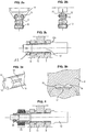
- FIGS. 3a and 3b illustrate an example with a strain gauge blades in which one of the screws 12 has in the right of one of the clevises of the fastener grooves 14 recessed on which extend the flexible blades 15 strain gauge.
- the strain gauge blades 15 are for example distributed at 120 degrees from each other.
- Punches 16 projecting on the yoke bear against the strain gauge blades and deform when the parts of the secondary track are loaded, either in tension or in compression.
- These effort detection means 20 are for example connected to the computer of the aircraft, which processes the measurements made by said means to deduce a charging of the secondary path and trigger if necessary the corresponding alarms.
- the figure 4 illustrates yet another example in which is interposed advantageously between the nut 13 associated with the screw 12 of attachment and the clevis of the part 8 that it comes to tighten a casing 23 spring.
- This casing 23 spring distributes the clamping force and makes independent loading of the gages of the force torque applied to the screw during assembly. This avoids false detections due to mounting conditions.
- the test device illustrated on the Figures 5 to 7 comprises a lever arm 30 pivotally mounted on a support 31. At its end opposite its gripping portion, the lever arm piece 30 terminates in a stop 32 intended to cooperate with a complementary U-shape 36 belonging to a tool 33, said stop 32 bearing on the inner flanks of the U-shaped in which it is received when the lever arm is tilted in one direction or the other.
- the support 31 may be an attached vice, for example screwed, on a mechanically decoupled structure with respect to the secondary path, in this case on the gimbal system 4 of the primary path.
- Other embodiments would of course be conceivable.
- the support 31 could in particular be based on a part of the primary track or on the structure of the aircraft itself.
- the tool 33 encloses at least one element of the high fastener of the secondary track in a manner that makes it possible to exert on said high fastener, by tilting of the lever arm 30 and transmission of a force by putting in support of the abutment 32 on the inner flanks of the U-shape 36, either a tensile force, a compression force, or even, as in the a case which is here exemplified, a tensile force or a compressive force in the direction of tilting of the lever arm 30.
- This clipping tool 33 is in this case made by assembling two front and rear plates 34, by means of two clasping screws 35a and 35b, which are positioned in a reduced space between a clevis edge of the part 8 and a rim that presents, at the right of this edge, the piece which constitutes the female form 10.
- clamping tool 33 can only bear on the upper part of the part 8 and only allow to exercise a compressive force.
- the tool 33 is able to bear on at least one zone of at least one element of the secondary path.
- the tool 33 comprising in particular the front and rear plates 34 linked by the tightening screws 35a, 35b, is able to clamp around an area of an element of the upper fastener of the secondary track, as illustrated for example in figure 7 .
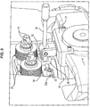
- the figures 8 and 9 illustrate an effort setting of the secondary path by the test device.
- the figure 9 illustrates an effort in the opposite direction.
- a first possibility is to position an operator in the cockpit of the aircraft, the role of which is to verify that an alarm, which is triggered when the detection means have detected a charging of the secondary channel, has occurred. well triggered.
- Another possibility is to use a detector, which is connected to a computer of the aircraft in communication with the detection means 20.
- test device is dismounted from the aircraft by unscrewing the tightening screws 35a, 35b and dismounting the clamping vice 31.
Landscapes
- Engineering & Computer Science (AREA)
- Aviation & Aerospace Engineering (AREA)
- Manufacturing & Machinery (AREA)
- Transportation (AREA)
- Aerodynamic Tests, Hydrodynamic Tests, Wind Tunnels, And Water Tanks (AREA)
- Testing Of Devices, Machine Parts, Or Other Structures Thereof (AREA)
- Transmission Devices (AREA)
- Force Measurement Appropriate To Specific Purposes (AREA)
Claims (8)
- Vorrichtung zum Testen von Mitteln zur Erfassung der Belastung der Nebenleitung eines Stellglieds zur Flugsteuerung jenes Typs, der eine Hauptleitung und eine Nebenleitung umfasst, die geeignet ist, den Druck der Hauptleitung im Falle eines Ausfalls derselben wiederherzustellen, dadurch gekennzeichnet, dass sie ein Werkzeug (33) umfasst, das geeignet ist, sich auf zumindest einen Bereich mindestens eines Elements der Nebenleitung zu stützen, sowie einen Hebelarm (30), der durch Kippen dazu angepasst ist, das Aufstützen des Werkzeugs auf diesen Bereich zu ermöglichen, sodass es eine Zugkraft und/oder Druckkraft auf die Nebenleitung ausübt, wobei der Hebelarm (30) schwenkbar an einer Stütze (31) angebracht ist, die geeignet ist, an einer mechanisch von der Nebenleitung unabhängigen Struktur befestigt zu werden.
- Vorrichtung nach Anspruch 1, dadurch gekennzeichnet, dass das Werkzeug (33) geeignet ist, zumindest einen Bereich mindestens eines hoch angebrachten Elements der Nebenleitung einzuspannen.
- Vorrichtung nach Anspruch 2, wobei das Werkzeug (33) eine Einheit umfasst, die zwei durch zwei Schrauben (35a, 35b) verbundene Platten (34) zum Einspannen umfasst, die geeignet sind, einen Bereich eines hoch angebrachten Elements der Nebenleitung in Eingriff zu nehmen.
- Vorrichtung nach einem der Ansprüche 1 bis 3, dadurch gekennzeichnet, dass das Werkzeug (33) eine U-Form (36) aufweist, in der ein Anschlag (32) aufgenommen wird, der den armbildenden Hebel (30) an seinem Ende gegenüber dem Greifende beendet, wobei der Anschlag (32) beim Kippen des Hebelarms (30) in die eine oder andere Richtung gegen die eine und/oder die andere von zwei Innenflanken in U-Form (36) zur Anlage kommt und damit ermöglicht, in die eine oder andere Richtung einen Druck auf die Nebenleitung auszuüben.
- Vorrichtung nach einem der vorhergehenden Ansprüche, wobei die Stütze (31) einen Schraubstock umfasst, der geeignet ist, auf einem Teil der Hauptleitung oder der Struktur eines Luftfahrzeugs angebracht zu werden.
- Verfahren zum Testen von Mitteln zur Erfassung der Belastung der Nebenleitung eines Stellglieds zur Flugsteuerung jenes Typs, der eine Hauptleitung und eine Nebenleitung umfasst, die geeignet ist, den Druck der Hauptleitung im Falle eines Ausfalls derselben wiederherzustellen, dadurch gekennzeichnet, dass eine Zugkraft und/oder Druckkraft auf die Nebenleitung ausgeübt wird, und zwar mittels eines Werkzeugs (33), das geeignet ist, sich auf zumindest einen Bereich mindestens eines Elements der Nebenleitung zu stützen, sowie mittels eines Hebelarms (30), der durch Kippen das Aufstützen des Werkzeugs (33) ermöglicht, damit es besagte Zugkraft und/oder Druckkraft auf die Nebenleitung ausübt, wobei der Hebelarm (30) schwenkbar an einer Stütze (31) angebracht ist, die geeignet ist, an einer mechanisch von der Nebenleitung unabhängigen Struktur befestigt zu werden.
- Verfahren nach Anspruch 6, wobei das Werkzeug (33) geeignet ist, zumindest einen Bereich mindestens eines hoch angebrachten Elements der Nebenleitung einzuspannen, die Stütze (31) des Hebelarms (30) auf einer mechanisch von der Nebenleitung unabhängigen Struktur befestigt wird und das Einspannwerkzeug (33) um einen Bereich eines hoch angebrachten Elements der Nebenleitung befestigt wird, um den Bereich in Eingriff zu nehmen.
- Verfahren nach einem der Ansprüche 6 oder 7, einen vorherigen Schritt der Lockerung eines Federgehäuses (23) und einer Schraubenmutter (13) umfassend, um mechanische Reibungen zu verhindern, um die Rückstellung der Mittel (20) zur Erfassung der Belastung der Nebenleitung auf Null zu ermöglichen, sowie einen Schritt der Neuspannung des Federgehäuses (23) und der Schraubenmutter (13) am Ende des Tests.
Applications Claiming Priority (1)
| Application Number | Priority Date | Filing Date | Title |
|---|---|---|---|
| FR0958738A FR2953494B1 (fr) | 2009-12-08 | 2009-12-08 | Dispositif de test de la detection de la reprise effort par une voie secondaire d'un actionneur de commande de vol, et procede de test associe |
Publications (2)
| Publication Number | Publication Date |
|---|---|
| EP2332838A1 EP2332838A1 (de) | 2011-06-15 |
| EP2332838B1 true EP2332838B1 (de) | 2016-07-13 |
Family
ID=42308330
Family Applications (1)
| Application Number | Title | Priority Date | Filing Date |
|---|---|---|---|
| EP10194205.0A Active EP2332838B1 (de) | 2009-12-08 | 2010-12-08 | Testvorrichtung zur Erfassung der Wiederherstellung des Drucks über eine Nebenleitung eines Stellglieds zur Flugsteuerung, und entsprechendes Testverfahren |
Country Status (4)
| Country | Link |
|---|---|
| US (1) | US8702034B2 (de) |
| EP (1) | EP2332838B1 (de) |
| CA (1) | CA2724857C (de) |
| FR (1) | FR2953494B1 (de) |
Families Citing this family (13)
| Publication number | Priority date | Publication date | Assignee | Title |
|---|---|---|---|---|
| FR2953494B1 (fr) * | 2009-12-08 | 2012-02-17 | Goodrich Actuation Systems Sas | Dispositif de test de la detection de la reprise effort par une voie secondaire d'un actionneur de commande de vol, et procede de test associe |
| FR2959837B1 (fr) * | 2010-05-07 | 2012-05-04 | Eurocopter France | Systeme de commandes de vol simplifiees comportant un dispositif de friction debrayable |
| FR3016607B1 (fr) * | 2014-01-20 | 2016-01-22 | Sagem Defense Securite | Actionneur de commande d'un plan horizontal de stabilisation d'un aeronef |
| EP3227583B1 (de) * | 2014-12-01 | 2021-04-14 | Goodrich Actuation Systems SAS | Aktuator für horizontaler flugzeugstabilisator mit erfassung des spieles und entsprechendes verfahren |
| EP3072808B1 (de) | 2015-03-26 | 2017-10-25 | Goodrich Actuation Systems SAS | Obere befestigung für einen trimmbaren horizontalen stabilisatoraktuator |
| EP3072809B1 (de) | 2015-03-27 | 2020-07-15 | Goodrich Actuation Systems SAS | Untere befestigung für einen trimmbaren horizontalen stabilisatoraktuator |
| EP3081481B1 (de) * | 2015-04-15 | 2021-09-22 | Goodrich Actuation Systems SAS | Prüfvorrichtung für eine vorrichtung zur fehlererkennung des primären lastpfades eines flugaktuators |
| CA2919342C (en) | 2015-04-15 | 2023-08-15 | Goodrich Actuation Systems Sas | Check device for flight actuator primary load path failure detection device |
| US10444128B2 (en) * | 2016-10-10 | 2019-10-15 | The Boeing Company | Load path status detection system |
| US10974846B2 (en) * | 2016-12-09 | 2021-04-13 | Parker-Hannifin Corporation | Fixed end electronic detection of secondary load path engagement of aircraft flight control actuator |
| EP3404395B1 (de) | 2017-05-19 | 2020-01-29 | Goodrich Actuation Systems SAS | Testverfahren und testvorrichtung für flugstellglied-prüfvorrichtung |
| EP3403925B1 (de) * | 2017-05-19 | 2021-03-31 | Goodrich Actuation Systems SAS | Unteres befestigungssystem für ein trimmbares horizontales stabilisatorstellglied |
| CN108170152B (zh) * | 2017-12-04 | 2020-12-29 | 中国飞机强度研究所 | 一种飞机航向约束点误差主动控制方法 |
Family Cites Families (17)
| Publication number | Priority date | Publication date | Assignee | Title |
|---|---|---|---|---|
| GB749253A (en) * | 1953-01-30 | 1956-05-23 | Northrop Aircraft Inc | Improvements in or relating to control system for an airplane |
| US5628477A (en) * | 1995-02-13 | 1997-05-13 | The Boeing Company | Auxiliary airfoil lost motion detector and actuator |
| US6389915B1 (en) * | 1999-05-17 | 2002-05-21 | Alliedsignal, Inc. | Dual load path ball screw with rod end swivel |
| FR2811780B1 (fr) * | 2000-07-13 | 2002-08-30 | Aerospatiale Matra Airbus | Procede et dispositif de commande d'organes de manoeuvre d'un aeronef, a modules de secours electriques |
| US6578425B2 (en) * | 2001-05-29 | 2003-06-17 | Honeywell Inc. | Apparatus and method for verifying the dynamic stiffness capability of hydraulic servo actuators |
| US6659399B1 (en) * | 2002-11-25 | 2003-12-09 | The Boeing Company | Compact linear split sleeves for accurate rigging in confined space |
| US6672540B1 (en) * | 2002-12-03 | 2004-01-06 | Rockwell Collins, Inc. | Actuator for aircraft stabilizers with a failure responsive lock control mechanism |
| ITRM20030169A1 (it) * | 2003-04-11 | 2004-10-12 | Umbra Cuscinetti Spa | Attuatore a ricircolo di sfere per superfici di governo di aermobili. |
| US7607611B2 (en) * | 2005-05-11 | 2009-10-27 | Honeywell International Inc. | Flight control surface actuation system with redundantly configured and lockable actuator assemblies |
| FR2891051B1 (fr) * | 2005-09-22 | 2007-10-19 | Airbus France Sas | Procede et dispositif pour realiser au moins un essai en vol sur un aeronef et applications |
| US7690597B2 (en) * | 2006-07-17 | 2010-04-06 | Eaton Corporation | Flap actuator |
| US7641145B2 (en) * | 2006-11-21 | 2010-01-05 | Eaton Corporation | Apparatus for moving a control surface |
| FR2912374B1 (fr) * | 2007-02-08 | 2009-05-08 | Goodrich Actuation Systems Sas | Detection de la reprise d'effort par une voie secondaire d'un actionneur de commande de vol |
| FR2913949B1 (fr) * | 2007-03-23 | 2009-10-02 | Goodrich Actuation Systems Sas | Perfectionnements a la detection de la reprise d'effort de la voie secondaire d'un actionneur de commande de vol. |
| FR2916023B1 (fr) * | 2007-05-11 | 2009-08-21 | Goodrich Actuation Systems Sas | Liaison mecanique fusible entre deux ecrous sur un ensemble a vis de securite a defaillance. |
| US7686680B2 (en) * | 2007-06-26 | 2010-03-30 | Honeywell International Inc. | Closed-loop cabin pressure control system test method with actual pressure feedback |
| FR2953494B1 (fr) * | 2009-12-08 | 2012-02-17 | Goodrich Actuation Systems Sas | Dispositif de test de la detection de la reprise effort par une voie secondaire d'un actionneur de commande de vol, et procede de test associe |
-
2009
- 2009-12-08 FR FR0958738A patent/FR2953494B1/fr active Active
-
2010
- 2010-12-08 US US12/962,883 patent/US8702034B2/en active Active
- 2010-12-08 CA CA2724857A patent/CA2724857C/fr active Active
- 2010-12-08 EP EP10194205.0A patent/EP2332838B1/de active Active
Also Published As
| Publication number | Publication date |
|---|---|
| CA2724857C (fr) | 2018-03-06 |
| FR2953494A1 (fr) | 2011-06-10 |
| EP2332838A1 (de) | 2011-06-15 |
| US8702034B2 (en) | 2014-04-22 |
| US20110132106A1 (en) | 2011-06-09 |
| FR2953494B1 (fr) | 2012-02-17 |
| CA2724857A1 (fr) | 2011-06-08 |
Similar Documents
| Publication | Publication Date | Title |
|---|---|---|
| EP2332838B1 (de) | Testvorrichtung zur Erfassung der Wiederherstellung des Drucks über eine Nebenleitung eines Stellglieds zur Flugsteuerung, und entsprechendes Testverfahren | |
| EP2000405B1 (de) | Perfektionierungen der Erfassung des Drucks auf ein Stellglied zur Flugsteuerung | |
| EP2563655B1 (de) | Vorrichtung zum erkennen des bruchs eines primärpfads in einem flugsteuerungsaktuator | |
| EP2164685B1 (de) | Klemme für handhabungsroboter mit verbesserter greifgenauigkeit und mindestens eine solche klemme umfassender handhabungsroboter | |
| CA2753950C (fr) | Train d'atterrissage a patins et aeronef muni d'un tel train d'atterrissage | |
| WO2015107208A2 (fr) | Actionneur de commande d'un plan horizontal de stabilisation d'un aeronef | |
| EP3636474A1 (de) | Verriegelungsvorrichtung, insbesondere aufbewahrungsvorrichtung für atemmaske zur sauerstoffversorgung in einem luftfahrzeug, und sauerstoffzuführsystem | |
| EP3015368A1 (de) | Befestigungsvorrichtung für einen motor eines luftfahrzeugs, und entsprechendes luftfahrzeug | |
| EP2665644B1 (de) | Verbesserungen an flugsteuerungsaktuatoren mit einer sekundären mutter | |
| WO2020136356A1 (fr) | Dispositif d'application d'effort pour un manche de pilotage d'un aéronef | |
| EP2439140B1 (de) | Zapfenbefestigung mit Mittel zur Messung der durch einen Luftfahrzeugantrieb erzeugten Kräfte | |
| FR3058986A1 (fr) | Attache arriere d'un moteur d'aeronef comportant des temoins de rupture | |
| EP3398819A1 (de) | Befestigungsvorrichtung eines sicherheitsmoduls auf dem lenkrad eines fahrzeugs | |
| FR3093704A1 (fr) | Attache moteur arrière d’un ensemble propulsif d’aéronef | |
| FR2979899A1 (fr) | Dispositif d'attelage d'un actionneur de manoeuvre d'un atterrisseur d'aeronef | |
| FR2950429A1 (fr) | Dispositif de mesure d'un torseur des efforts et des moments generes par un ensemble propulsif d'aeronef | |
| FR3100530A1 (fr) | Ensemble de motorisation d’aéronef comprenant un dispositif de reprise d’efforts de poussée | |
| FR3096350A1 (fr) | Systeme d’attache moteur avant pour un moteur d’aeronef comportant une poutre realisee en trois parties | |
| FR3082826A1 (fr) | Interface de fixation, systeme de flottaison et vehicule | |
| EP4159616A1 (de) | Hindernis zum sichern eines luftfahrzeugs auf einem landegitter und luftfahrzeug | |
| FR2893910A1 (fr) | Dispositif de detection d'une defaillance d'une gouverne de vol d'un aeronef | |
| WO2015004124A1 (fr) | Anneau de levage | |
| FR3029162A1 (fr) | Agencement pour vehicule automobile muni d'une entretoise ajustable disposee entre deux elements de structure | |
| EP2192373B1 (de) | Vorrichtung zur automatischen Entkoppelung von zwei Teilen eines Verbinders | |
| FR3066561A1 (fr) | Ferrure formant fusible pour un systeme d'entrainement en translation d'un verin |
Legal Events
| Date | Code | Title | Description |
|---|---|---|---|
| PUAI | Public reference made under article 153(3) epc to a published international application that has entered the european phase |
Free format text: ORIGINAL CODE: 0009012 |
|
| 17P | Request for examination filed |
Effective date: 20101208 |
|
| AK | Designated contracting states |
Kind code of ref document: A1 Designated state(s): AL AT BE BG CH CY CZ DE DK EE ES FI FR GB GR HR HU IE IS IT LI LT LU LV MC MK MT NL NO PL PT RO RS SE SI SK SM TR |
|
| AX | Request for extension of the european patent |
Extension state: BA ME |
|
| RIC1 | Information provided on ipc code assigned before grant |
Ipc: F16H 25/20 20060101ALN20151120BHEP Ipc: B64C 13/36 20060101ALI20151120BHEP Ipc: B64C 13/28 20060101ALI20151120BHEP Ipc: B64C 13/42 20060101ALI20151120BHEP Ipc: B64F 5/00 20060101AFI20151120BHEP |
|
| GRAP | Despatch of communication of intention to grant a patent |
Free format text: ORIGINAL CODE: EPIDOSNIGR1 |
|
| INTG | Intention to grant announced |
Effective date: 20160118 |
|
| RIC1 | Information provided on ipc code assigned before grant |
Ipc: B64C 13/28 20060101ALI20160108BHEP Ipc: B64C 13/36 20060101ALI20160108BHEP Ipc: B64F 5/00 20060101AFI20160108BHEP Ipc: F16H 25/20 20060101ALN20160108BHEP Ipc: B64C 13/42 20060101ALI20160108BHEP |
|
| GRAS | Grant fee paid |
Free format text: ORIGINAL CODE: EPIDOSNIGR3 |
|
| GRAA | (expected) grant |
Free format text: ORIGINAL CODE: 0009210 |
|
| AK | Designated contracting states |
Kind code of ref document: B1 Designated state(s): AL AT BE BG CH CY CZ DE DK EE ES FI GB GR HR HU IE IS IT LI LT LU LV MC MK MT NL NO PL PT RO RS SE SI SK SM TR |
|
| RBV | Designated contracting states (corrected) |
Designated state(s): AL AT BE BG CH CY CZ DE DK EE ES FI GB GR HR HU IE IS IT LI LT LU LV MC MK MT NL NO PL PT RO RS SE SI SK SM TR |
|
| REG | Reference to a national code |
Ref country code: GB Ref legal event code: FG4D Free format text: NOT ENGLISH |
|
| REG | Reference to a national code |
Ref country code: AT Ref legal event code: REF Ref document number: 812063 Country of ref document: AT Kind code of ref document: T Effective date: 20160715 Ref country code: CH Ref legal event code: EP |
|
| REG | Reference to a national code |
Ref country code: IE Ref legal event code: FG4D Free format text: LANGUAGE OF EP DOCUMENT: FRENCH |
|
| REG | Reference to a national code |
Ref country code: DE Ref legal event code: R096 Ref document number: 602010034621 Country of ref document: DE |
|
| REG | Reference to a national code |
Ref country code: LT Ref legal event code: MG4D |
|
| REG | Reference to a national code |
Ref country code: NL Ref legal event code: MP Effective date: 20160713 |
|
| REG | Reference to a national code |
Ref country code: AT Ref legal event code: MK05 Ref document number: 812063 Country of ref document: AT Kind code of ref document: T Effective date: 20160713 |
|
| PG25 | Lapsed in a contracting state [announced via postgrant information from national office to epo] |
Ref country code: RS Free format text: LAPSE BECAUSE OF FAILURE TO SUBMIT A TRANSLATION OF THE DESCRIPTION OR TO PAY THE FEE WITHIN THE PRESCRIBED TIME-LIMIT Effective date: 20160713 Ref country code: LT Free format text: LAPSE BECAUSE OF FAILURE TO SUBMIT A TRANSLATION OF THE DESCRIPTION OR TO PAY THE FEE WITHIN THE PRESCRIBED TIME-LIMIT Effective date: 20160713 Ref country code: HR Free format text: LAPSE BECAUSE OF FAILURE TO SUBMIT A TRANSLATION OF THE DESCRIPTION OR TO PAY THE FEE WITHIN THE PRESCRIBED TIME-LIMIT Effective date: 20160713 Ref country code: IS Free format text: LAPSE BECAUSE OF FAILURE TO SUBMIT A TRANSLATION OF THE DESCRIPTION OR TO PAY THE FEE WITHIN THE PRESCRIBED TIME-LIMIT Effective date: 20161113 Ref country code: FI Free format text: LAPSE BECAUSE OF FAILURE TO SUBMIT A TRANSLATION OF THE DESCRIPTION OR TO PAY THE FEE WITHIN THE PRESCRIBED TIME-LIMIT Effective date: 20160713 Ref country code: NL Free format text: LAPSE BECAUSE OF FAILURE TO SUBMIT A TRANSLATION OF THE DESCRIPTION OR TO PAY THE FEE WITHIN THE PRESCRIBED TIME-LIMIT Effective date: 20160713 Ref country code: NO Free format text: LAPSE BECAUSE OF FAILURE TO SUBMIT A TRANSLATION OF THE DESCRIPTION OR TO PAY THE FEE WITHIN THE PRESCRIBED TIME-LIMIT Effective date: 20161013 |
|
| PG25 | Lapsed in a contracting state [announced via postgrant information from national office to epo] |
Ref country code: PT Free format text: LAPSE BECAUSE OF FAILURE TO SUBMIT A TRANSLATION OF THE DESCRIPTION OR TO PAY THE FEE WITHIN THE PRESCRIBED TIME-LIMIT Effective date: 20161114 Ref country code: LV Free format text: LAPSE BECAUSE OF FAILURE TO SUBMIT A TRANSLATION OF THE DESCRIPTION OR TO PAY THE FEE WITHIN THE PRESCRIBED TIME-LIMIT Effective date: 20160713 Ref country code: GR Free format text: LAPSE BECAUSE OF FAILURE TO SUBMIT A TRANSLATION OF THE DESCRIPTION OR TO PAY THE FEE WITHIN THE PRESCRIBED TIME-LIMIT Effective date: 20161014 Ref country code: ES Free format text: LAPSE BECAUSE OF FAILURE TO SUBMIT A TRANSLATION OF THE DESCRIPTION OR TO PAY THE FEE WITHIN THE PRESCRIBED TIME-LIMIT Effective date: 20160713 Ref country code: AT Free format text: LAPSE BECAUSE OF FAILURE TO SUBMIT A TRANSLATION OF THE DESCRIPTION OR TO PAY THE FEE WITHIN THE PRESCRIBED TIME-LIMIT Effective date: 20160713 Ref country code: SE Free format text: LAPSE BECAUSE OF FAILURE TO SUBMIT A TRANSLATION OF THE DESCRIPTION OR TO PAY THE FEE WITHIN THE PRESCRIBED TIME-LIMIT Effective date: 20160713 Ref country code: PL Free format text: LAPSE BECAUSE OF FAILURE TO SUBMIT A TRANSLATION OF THE DESCRIPTION OR TO PAY THE FEE WITHIN THE PRESCRIBED TIME-LIMIT Effective date: 20160713 |
|
| REG | Reference to a national code |
Ref country code: DE Ref legal event code: R097 Ref document number: 602010034621 Country of ref document: DE |
|
| PG25 | Lapsed in a contracting state [announced via postgrant information from national office to epo] |
Ref country code: EE Free format text: LAPSE BECAUSE OF FAILURE TO SUBMIT A TRANSLATION OF THE DESCRIPTION OR TO PAY THE FEE WITHIN THE PRESCRIBED TIME-LIMIT Effective date: 20160713 Ref country code: RO Free format text: LAPSE BECAUSE OF FAILURE TO SUBMIT A TRANSLATION OF THE DESCRIPTION OR TO PAY THE FEE WITHIN THE PRESCRIBED TIME-LIMIT Effective date: 20160713 |
|
| PLBE | No opposition filed within time limit |
Free format text: ORIGINAL CODE: 0009261 |
|
| STAA | Information on the status of an ep patent application or granted ep patent |
Free format text: STATUS: NO OPPOSITION FILED WITHIN TIME LIMIT |
|
| PG25 | Lapsed in a contracting state [announced via postgrant information from national office to epo] |
Ref country code: SM Free format text: LAPSE BECAUSE OF FAILURE TO SUBMIT A TRANSLATION OF THE DESCRIPTION OR TO PAY THE FEE WITHIN THE PRESCRIBED TIME-LIMIT Effective date: 20160713 Ref country code: BE Free format text: LAPSE BECAUSE OF NON-PAYMENT OF DUE FEES Effective date: 20161231 Ref country code: DK Free format text: LAPSE BECAUSE OF FAILURE TO SUBMIT A TRANSLATION OF THE DESCRIPTION OR TO PAY THE FEE WITHIN THE PRESCRIBED TIME-LIMIT Effective date: 20160713 Ref country code: BG Free format text: LAPSE BECAUSE OF FAILURE TO SUBMIT A TRANSLATION OF THE DESCRIPTION OR TO PAY THE FEE WITHIN THE PRESCRIBED TIME-LIMIT Effective date: 20161013 Ref country code: CZ Free format text: LAPSE BECAUSE OF FAILURE TO SUBMIT A TRANSLATION OF THE DESCRIPTION OR TO PAY THE FEE WITHIN THE PRESCRIBED TIME-LIMIT Effective date: 20160713 Ref country code: SK Free format text: LAPSE BECAUSE OF FAILURE TO SUBMIT A TRANSLATION OF THE DESCRIPTION OR TO PAY THE FEE WITHIN THE PRESCRIBED TIME-LIMIT Effective date: 20160713 |
|
| 26N | No opposition filed |
Effective date: 20170418 |
|
| REG | Reference to a national code |
Ref country code: CH Ref legal event code: PL |
|
| PG25 | Lapsed in a contracting state [announced via postgrant information from national office to epo] |
Ref country code: SI Free format text: LAPSE BECAUSE OF FAILURE TO SUBMIT A TRANSLATION OF THE DESCRIPTION OR TO PAY THE FEE WITHIN THE PRESCRIBED TIME-LIMIT Effective date: 20160713 |
|
| PG25 | Lapsed in a contracting state [announced via postgrant information from national office to epo] |
Ref country code: MC Free format text: LAPSE BECAUSE OF FAILURE TO SUBMIT A TRANSLATION OF THE DESCRIPTION OR TO PAY THE FEE WITHIN THE PRESCRIBED TIME-LIMIT Effective date: 20160713 |
|
| REG | Reference to a national code |
Ref country code: IE Ref legal event code: MM4A |
|
| PG25 | Lapsed in a contracting state [announced via postgrant information from national office to epo] |
Ref country code: CH Free format text: LAPSE BECAUSE OF NON-PAYMENT OF DUE FEES Effective date: 20161231 Ref country code: LU Free format text: LAPSE BECAUSE OF NON-PAYMENT OF DUE FEES Effective date: 20161208 Ref country code: LI Free format text: LAPSE BECAUSE OF NON-PAYMENT OF DUE FEES Effective date: 20161231 |
|
| PG25 | Lapsed in a contracting state [announced via postgrant information from national office to epo] |
Ref country code: IE Free format text: LAPSE BECAUSE OF NON-PAYMENT OF DUE FEES Effective date: 20161208 |
|
| REG | Reference to a national code |
Ref country code: BE Ref legal event code: MM Effective date: 20161231 |
|
| PG25 | Lapsed in a contracting state [announced via postgrant information from national office to epo] |
Ref country code: CY Free format text: LAPSE BECAUSE OF FAILURE TO SUBMIT A TRANSLATION OF THE DESCRIPTION OR TO PAY THE FEE WITHIN THE PRESCRIBED TIME-LIMIT Effective date: 20160713 Ref country code: HU Free format text: LAPSE BECAUSE OF FAILURE TO SUBMIT A TRANSLATION OF THE DESCRIPTION OR TO PAY THE FEE WITHIN THE PRESCRIBED TIME-LIMIT; INVALID AB INITIO Effective date: 20101208 |
|
| PG25 | Lapsed in a contracting state [announced via postgrant information from national office to epo] |
Ref country code: TR Free format text: LAPSE BECAUSE OF FAILURE TO SUBMIT A TRANSLATION OF THE DESCRIPTION OR TO PAY THE FEE WITHIN THE PRESCRIBED TIME-LIMIT Effective date: 20160713 Ref country code: MK Free format text: LAPSE BECAUSE OF FAILURE TO SUBMIT A TRANSLATION OF THE DESCRIPTION OR TO PAY THE FEE WITHIN THE PRESCRIBED TIME-LIMIT Effective date: 20160713 |
|
| PG25 | Lapsed in a contracting state [announced via postgrant information from national office to epo] |
Ref country code: MT Free format text: LAPSE BECAUSE OF FAILURE TO SUBMIT A TRANSLATION OF THE DESCRIPTION OR TO PAY THE FEE WITHIN THE PRESCRIBED TIME-LIMIT Effective date: 20160713 |
|
| PG25 | Lapsed in a contracting state [announced via postgrant information from national office to epo] |
Ref country code: AL Free format text: LAPSE BECAUSE OF FAILURE TO SUBMIT A TRANSLATION OF THE DESCRIPTION OR TO PAY THE FEE WITHIN THE PRESCRIBED TIME-LIMIT Effective date: 20160713 |
|
| REG | Reference to a national code |
Ref country code: DE Ref legal event code: R082 Ref document number: 602010034621 Country of ref document: DE |
|
| PGFP | Annual fee paid to national office [announced via postgrant information from national office to epo] |
Ref country code: GB Payment date: 20251229 Year of fee payment: 16 |
|
| PGFP | Annual fee paid to national office [announced via postgrant information from national office to epo] |
Ref country code: IT Payment date: 20251209 Year of fee payment: 16 |
|
| PGFP | Annual fee paid to national office [announced via postgrant information from national office to epo] |
Ref country code: DE Payment date: 20251231 Year of fee payment: 16 |