EP2332859B1 - Installation de stockage d'article et son procédé de fonctionnement - Google Patents
Installation de stockage d'article et son procédé de fonctionnement Download PDFInfo
- Publication number
- EP2332859B1 EP2332859B1 EP09811371.5A EP09811371A EP2332859B1 EP 2332859 B1 EP2332859 B1 EP 2332859B1 EP 09811371 A EP09811371 A EP 09811371A EP 2332859 B1 EP2332859 B1 EP 2332859B1
- Authority
- EP
- European Patent Office
- Prior art keywords
- pair
- crane
- vertical movement
- vertically movable
- travel
- Prior art date
- Legal status (The legal status is an assumption and is not a legal conclusion. Google has not performed a legal analysis and makes no representation as to the accuracy of the status listed.)
- Active
Links
Images








Classifications
-
- B—PERFORMING OPERATIONS; TRANSPORTING
- B65—CONVEYING; PACKING; STORING; HANDLING THIN OR FILAMENTARY MATERIAL
- B65G—TRANSPORT OR STORAGE DEVICES, e.g. CONVEYORS FOR LOADING OR TIPPING, SHOP CONVEYOR SYSTEMS OR PNEUMATIC TUBE CONVEYORS
- B65G1/00—Storing articles, individually or in orderly arrangement, in warehouses or magazines
- B65G1/02—Storage devices
- B65G1/04—Storage devices mechanical
- B65G1/0407—Storage devices mechanical using stacker cranes
-
- B—PERFORMING OPERATIONS; TRANSPORTING
- B65—CONVEYING; PACKING; STORING; HANDLING THIN OR FILAMENTARY MATERIAL
- B65G—TRANSPORT OR STORAGE DEVICES, e.g. CONVEYORS FOR LOADING OR TIPPING, SHOP CONVEYOR SYSTEMS OR PNEUMATIC TUBE CONVEYORS
- B65G1/00—Storing articles, individually or in orderly arrangement, in warehouses or magazines
- B65G1/02—Storage devices
- B65G1/04—Storage devices mechanical
- B65G1/0407—Storage devices mechanical using stacker cranes
- B65G1/0421—Storage devices mechanical using stacker cranes with control for stacker crane operations
-
- B—PERFORMING OPERATIONS; TRANSPORTING
- B65—CONVEYING; PACKING; STORING; HANDLING THIN OR FILAMENTARY MATERIAL
- B65G—TRANSPORT OR STORAGE DEVICES, e.g. CONVEYORS FOR LOADING OR TIPPING, SHOP CONVEYOR SYSTEMS OR PNEUMATIC TUBE CONVEYORS
- B65G1/00—Storing articles, individually or in orderly arrangement, in warehouses or magazines
- B65G1/02—Storage devices
- B65G1/04—Storage devices mechanical
- B65G1/137—Storage devices mechanical with arrangements or automatic control means for selecting which articles are to be removed
- B65G1/1371—Storage devices mechanical with arrangements or automatic control means for selecting which articles are to be removed with data records
-
- B—PERFORMING OPERATIONS; TRANSPORTING
- B66—HOISTING; LIFTING; HAULING
- B66C—CRANES; LOAD-ENGAGING ELEMENTS OR DEVICES FOR CRANES, CAPSTANS, WINCHES, OR TACKLES
- B66C13/00—Other constructional features or details
- B66C13/18—Control systems or devices
- B66C13/46—Position indicators for suspended loads or for crane elements
-
- B—PERFORMING OPERATIONS; TRANSPORTING
- B66—HOISTING; LIFTING; HAULING
- B66C—CRANES; LOAD-ENGAGING ELEMENTS OR DEVICES FOR CRANES, CAPSTANS, WINCHES, OR TACKLES
- B66C13/00—Other constructional features or details
- B66C13/18—Control systems or devices
- B66C13/48—Automatic control of crane drives for producing a single or repeated working cycle; Program control
-
- B—PERFORMING OPERATIONS; TRANSPORTING
- B66—HOISTING; LIFTING; HAULING
- B66C—CRANES; LOAD-ENGAGING ELEMENTS OR DEVICES FOR CRANES, CAPSTANS, WINCHES, OR TACKLES
- B66C15/00—Safety gear
- B66C15/04—Safety gear for preventing collisions, e.g. between cranes or trolleys operating on the same track
- B66C15/045—Safety gear for preventing collisions, e.g. between cranes or trolleys operating on the same track electrical
-
- B—PERFORMING OPERATIONS; TRANSPORTING
- B66—HOISTING; LIFTING; HAULING
- B66F—HOISTING, LIFTING, HAULING OR PUSHING, NOT OTHERWISE PROVIDED FOR, e.g. DEVICES WHICH APPLY A LIFTING OR PUSHING FORCE DIRECTLY TO THE SURFACE OF A LOAD
- B66F9/00—Devices for lifting or lowering bulky or heavy goods for loading or unloading purposes
- B66F9/06—Devices for lifting or lowering bulky or heavy goods for loading or unloading purposes movable, with their loads, on wheels or the like, e.g. fork-lift trucks
- B66F9/07—Floor-to-roof stacking devices, e.g. "stacker cranes", "retrievers"
-
- B—PERFORMING OPERATIONS; TRANSPORTING
- B66—HOISTING; LIFTING; HAULING
- B66F—HOISTING, LIFTING, HAULING OR PUSHING, NOT OTHERWISE PROVIDED FOR, e.g. DEVICES WHICH APPLY A LIFTING OR PUSHING FORCE DIRECTLY TO THE SURFACE OF A LOAD
- B66F9/00—Devices for lifting or lowering bulky or heavy goods for loading or unloading purposes
- B66F9/06—Devices for lifting or lowering bulky or heavy goods for loading or unloading purposes movable, with their loads, on wheels or the like, e.g. fork-lift trucks
- B66F9/07—Floor-to-roof stacking devices, e.g. "stacker cranes", "retrievers"
- B66F9/072—Travelling gear therefor
-
- G—PHYSICS
- G06—COMPUTING OR CALCULATING; COUNTING
- G06Q—INFORMATION AND COMMUNICATION TECHNOLOGY [ICT] SPECIALLY ADAPTED FOR ADMINISTRATIVE, COMMERCIAL, FINANCIAL, MANAGERIAL OR SUPERVISORY PURPOSES; SYSTEMS OR METHODS SPECIALLY ADAPTED FOR ADMINISTRATIVE, COMMERCIAL, FINANCIAL, MANAGERIAL OR SUPERVISORY PURPOSES, NOT OTHERWISE PROVIDED FOR
- G06Q10/00—Administration; Management
- G06Q10/08—Logistics, e.g. warehousing, loading or distribution; Inventory or stock management
- G06Q10/087—Inventory or stock management, e.g. order filling, procurement or balancing against orders
Definitions
- the present invention relates to an article storage facility and method of operation therefor comprising an article storage rack having a plurality of storage units for storing articles, the storage units being arranged in a vertical direction and in a lateral direction; and a pair of stacker cranes configured to travel along a travel path provided on a front side of the article storage rack along a rack lateral width direction wherein each of the pair of stacker cranes having a traveling carriage guided by a travel guide rail extending along the travel path, and a vertically movable body including a vertically movable platform configured to be guided for vertical movement by a vertical movement guiding mast provided to stand on the traveling carriage and an article transfer device provided to the vertically movable platform for transferring an article to and from the storage units; a pair of travel position detection means for detecting respective travel positions of the traveling carriages of the pair of stacker cranes; a pair of vertical position detection means for detecting respective vertical positions of the vertically movable bodies of the pair of stacker cranes; and control means for controlling operations of the pair
- the conventional article storage facilities described above perform storage operations in which the articles to be transported are picked up from an article carry-in-and-out portion, such as an article receiving platform, and are unloaded to a storage unit, retrieval operations in which the articles stored in the storage unit are picked up and are unloaded to the article carry-in-and-out portion, and relocating operations in which articles from certain storage units are picked up and are unloaded to other storage units, by performing article transporting operations with stacker cranes.
- An article transporting operation of the stacker crane as the expression means an operation of the stacker crane involving a traveling operation of the traveling carriage or the vertical movement operation of the vertically movable body, and includes, not only the actual transporting operation in which the article transfer device supporting the article to be transported is-moved on the front side of the rack from the transport origin to the transport destination, but also includes, for example, an empty transporting operation in which the article transfer device supporting no article is moved to the transport origin by a travel operation and a vertical movement operation in order to pick up an article to be transported at the transport origin, as well as a return to origin operation in which the article transfer device supporting no article is moved to a home position in order to have the article transfer device stand by at the home position (starting point) arranged at an end in the direction of the travel path and at the lower end in the vertical direction to prepare for the subsequent storage operation after completing the storage operation.
- the control means is configured to control the operation of the stacker crane to perform an article transporting operation, such as an actual transporting operation or the empty transporting operation, and an article transfer operation, such as a pick up operation for the article at the transport origin (pick up transfer operation) and an unloading operation of the article at the transport destination (unloading transfer operation), in order to have the storage operation or retrieval operation performed based on the operation command.
- an article transporting operation such as an actual transporting operation or the empty transporting operation
- an article transfer operation such as a pick up operation for the article at the transport origin (pick up transfer operation) and an unloading operation of the article at the transport destination (unloading transfer operation
- the travel operation and vertical movement operation in the article transporting operation are operations performed in accordance with a travel speed pattern and a vertical movement speed pattern which are determined based on the positional relationship between the operation starting position and the operation end position of the actual transporting operation and the empty transporting operation based on the operation command, allowing efficient movements, taking as little time as possible from the operation starting position to the operation end position by performing a suitable travel operation and a suitable vertical movement operation.
- a large number of articles that can be stored and retrieved per unit time i.e., a high article throughput, which indicates the number of operation commands which can be processed, is desired to satisfy the need in the recent mass distribution age to shorten the time it takes to store and retrieve articles.
- various techniques are proposed to improve the article throughput in an article storage facility, it is suggested, for example, to provide a pair of stacker cranes, which can move along a travel path provided on the front side of the article storage rack and extending along the rack lateral width direction.
- the operation of the other stacker crane is controlled to move it out of the planned traveling range if the other stacker crane is not performing an article transporting operation as a stacker crane in duty (that is, it is in a standby state). And if the other stacker crane is performing an article transporting operation as a stacker crane in its duty, the operation of the other stacker crane is controlled to move it out of the planned traveling range after waiting for the article transporting operation by the stacker crane to be completed.
- Patent Document 1 discloses only one common travel guide rail arranged in the travel path and a pair of stacker cranes arranged on this travel guide rail and in the direction of the travel path. And an intermediate section of the travel path is designated to be the shared section in which both stacker cranes can travel, and an exclusive section - where only one stacker crane can move - is designated on either side of the shared section to coincide with the relative positioning of the cranes in the direction of the travel path. And in an avoidance operation, the other stacker crane is moved out along the travel direction. According to Fig.
- Patent Document 1 Japanese Patent Application Publication No. 2002-175117
- JP 2004 106 945 discloses an article storage facility acccording to the preamble of claim 1.
- EP 2 022 732 A2 is an intermediate document disclosing the features of claim 1, with exception of the determination of proximate positions at every set period.
- Patent Document 1 described above, if one try to process the operation command for the retrieval operation for the storage unit corresponding to the position which the stacker crane traveled past in an move-out operation by the stacker crane after the move-out operation is completed, both the other stacker crane which caused this stacker crane to move out and the stacker crane which was caused to move out will be performing the article transport operation as the responsible stacker crane. In this case, since the other stacker crane would present an obstacle to the stacker crane that was driven out, the completion of this operation command will be further delayed.
- the present invention was made in light of this point, and its object is to provide an article storage facility in which mutual interference between the pair of stacker cranes can be avoided without having to perform the avoidance operation that contributes to inefficiency as a consequence, as much as possible.
- the article storage facility comprises all features of claim 1. It comprises an article storage rack having a plurality of storage units for storing articles, the storage units being arranged in a vertical direction and in a lateral direction; and a pair of stacker cranes configured to travel along a travel path provided on a front side of the article storage rack along a rack lateral width direction, each of the pair of stacker cranes having a traveling carriage guided by a travel guide rail extending along the travel path, and a vertically movable body including a vertically movable platform configured to be guided for vertical movement by a vertical movement guiding mast provided to stand on the traveling carriage and an article transfer device provided to the vertically movable platform, for transferring an article to and from the storage units; a pair of travel position detection means for detecting respective travel positions of the traveling carriages of the pair of stacker cranes; a pair of vertical position detection means for detecting respective vertical positions of the vertically movable bodies of the pair of stacker cranes; control means for controlling
- the control means is configured, based on the operation command, to control an article transporting operation by an assigned stacker crane which is in charge of an article transport specified by the operation command, and to control each travel position of the pair of traveling carriages of the pair of stacker cranes based on the detected information from the pair of travel position detection means, and to determine, at every set period, whether respective travel positions of the pair of traveling carriages are at mutually proximate positions for which the pair of stacker crane are predicted to interfere with each other, while controlling the article transporting operation of the assigned stacker crane, and in that, when respective travel positions of the pair of traveling carriages are at the mutually proximate positions, the control means is configured to perform an interference avoidance process in which operations of the pair of stacker cranes are controlled to position the pair of traveling carriages and the pair of vertically movable bodies at non-interfering positions where the pair of stacker cranes would not interfere with each other, based on the
- control means determines whether respective travel positions of the pair of traveling carriages are at the mutually proximate positions at every set period while controlling the article transporting operation of the assigned stacker crane, it can be monitored whether they are at the mutually proximate positions while the stacker crane are carrying out the article transporting operations. And the control means performs the interference avoidance process when they are at the mutually proximate positions. Therefore, if the cranes are not at the mutually proximate positions at the beginning of the control of the article transporting operations of the assigned stacker crane, the article transporting operation of the assigned stacker crane is started, and simultaneously, each travel position of the pair of traveling carriage will begin to be monitored.
- the interference avoidance process is performed to position the pair of traveling carriages and the pair of vertically movable bodies at the non-interfering positions in which the pair of stacker cranes would not interfere with each other.
- the article transporting operation is continued without executing the operation for avoiding interference, until respective travel positions of the pair of traveling carriages reach the mutually proximate positions, even if the other stacker crane is in the planned traveling range for the article transporting operation.
- the article transporting operation is being performed, it is monitored whether respective travel positions of the pair of traveling carriages are at the mutually proximate positions for which the pair of stacker cranes are predicted to interfere with each other. And the pair of stacker cranes can avoid interfering with each other because the interference avoidance process is started when the respective travel positions of the pair of traveling carriages reach the mutually proximate positions.
- control means is preferably configured to determine that respective travel positions of the pair of traveling carriages are at the mutually proximate positions when there is an overlap between respective hypothetical braking ranges of respective traveling carriages, which range being a range covered by each traveling carriage from a current position until the time the traveling carriage stops, assuming that each of the pair of traveling carriages is stopped by decelerating at a set deceleration.
- the pair of stacker cranes will not interfere with each other depending on the movements in the subsequent article transporting operation. For example, if the traveling carriages which are traveling toward each other are separated by a distance which is greater than the sum of the hypothetical braking ranges for the respective traveling carriages, it is not possible for the pair of stacker cranes to interfere with each other regardless of their vertical movement operations based on the article transfer operations because they will come to stop without the traveling carriages overlapping with each other in the direction of the travel path if they actually decelerate at a set deceleration.
- the traveling carriages are separated by a distance which is greater than the sum of the hypothetical braking ranges for the respective traveling carriages as described above, it is determined that they are not at mutually proximate positions and the interference avoidance operation is not executed; thus, the vertical movement operations based on the article transfer operations are continued.
- the hypothetical braking range is used even when the travel speed of traveling carriage is zero, in which case the hypothetical braking range will have zero width, and it can be determined that there is an overlap if its position is in the hypothetical braking range of the other crane.
- control means is preferably configured to perform the interference avoidance process by controlling an operation of only one of the pair of stacker cranes.
- control means is preferably configured to perform the interference avoidance process by controlling an operation of an unassigned stacker crane which is not performing the article transporting operation between the pair of stacker cranes when the control means is causing only one of the pair of stacker cranes to perform the article transporting operation as an assigned stacker crane.
- interference between the stacker cranes is avoided by operating by the interference avoidance process the unassigned stacker crane, which does not contribute directly to maintaining or improving the article throughput without interrupting the article transporting operation of the assigned stacker crane which directly contributes to maintaining or improving the article throughput.
- Deterioration in the article throughput of the facility by the avoidance operation can be prevented by selecting the crane suitable as a stacker crane for executing the avoidance operation in this manner.
- control means is preferably configured to perform the interference avoidance process by controlling an operation of an assigned stacker crane with a longer remaining operation time for the article transporting operation between the pair of stacker cranes when the control means is causing both of the pair of stacker cranes to individually perform the article transporting operation as assigned stacker cranes.
- interference between the stacker cranes can be avoided by causing the assigned stacker crane, for which a recovery operation time to make up for the delay from the original article transporting operation is easy to secure because of the comparatively long remaining operation time, to be operated by the interference avoidance process, without interrupting the article transporting operation being performed by the assigned stacker crane for which a recovery operation time to make up for the delay from the original article transporting operation is difficult to secure because of the comparatively short remaining operation time.
- Deterioration in the article throughput of the facility by the avoidance operation can be minimized by selecting the crane suitable as a stacker crane for executing the avoidance operation in this manner.
- a pair of travel guide rails which are spaced apart in a rack fore and aft direction and which are parallel with each other is provided as the travel guide rail.
- a stacker crane with its traveling carriage guided by one of the pair of travel guide rails and with a vertical movement guiding mast provided to the traveling carriage, and another stacker crane with its traveling carriage guided by the other of the pair of travel guide rails and with a vertical movement guiding mast provided to the traveling carriage are provided as the pair of stacker cranes.
- Each of the pair of vertically movable bodies has a portion which overlaps with the vertically movable body of the other stacker crane in the rack fore and aft direction, and extends in the rack fore and aft direction from the vertical movement guiding mast so as not to reach the vertical movement guiding mast of the other stacker crane so that each of the pair of stacker cranes can pass each other.
- control means is preferably configured to execute an interference avoidance vertical movement process, as the interference avoidance process, in which vertical movements of the pair of vertically movable bodies are controlled to raise or lower the pair of vertically movable bodies to vertical positions for passing each other which are spaced apart in a vertical movement direction by a distance greater than or equal to a required separating distance which is defined as a separating distance which allows the pair of stacker cranes to pass each other without interfering with each other.
- each traveling carriage of the pair of stacker cranes travels on a respective one of the pair of travel guide rails which are spaced apart in the rack fore and aft direction and which are parallel with each other.
- each vertically movable body extends in the rack fore and aft direction from the vertical movement guiding mast so as not to reach the vertical movement guiding mast of the other stacker crane so that the pair of stacker cranes can pass each other, each stacker crane can travel over the entire rack lateral width in the rack lateral width direction on the front side of the article storage rack, regardless of the travel position of the other stacker crane.
- the article throughput does not improve appreciatively despite the fact that a pair of stacker cranes are provided.
- the cranes can travel over the entire rack lateral width in the rack lateral width direction regardless of the position of the other stacker crane with respect to the travel movement. Therefore, a facility that is convenient to use is provided when providing a pair of stacker crane to improve the article transporting capacity.
- each vertically movable body of the pair of stacker cranes has a portion that overlaps with the vertically movable body of the other stacker crane in the rack fore and aft direction, the travel paths required by each of the stacker cranes overlap in part in the rack fore and aft direction, therefore, the travel paths for the two stacker cranes can be made narrower than a width which is obtained by simply doubling the width for one crane. Therefore, installation space for providing a pair of stacker cranes to be arranged in the rack fore and aft direction can be made compact.
- the control means executes the interference avoidance vertical movement process as an interference avoidance process to control the vertical movement operations of the pair of vertically movable bodies when the travel positions of the traveling carriages of the pair of stacker crane are at the mutually proximate positions, to raise and lower the pair of vertically movable bodies to the vertical positions for passing each other which are spaced apart in the vertical movement direction by a distance greater than or equal to the required separating distance which is defined as a separating distance which allows the pair of stacker cranes to pass each other without interfering with each other, the pair of stacker crane can perform the article transporting operations by traveling in the rack lateral width direction over the entire rack lateral width without interfering with each other.
- the above-described configuration provides for an article storage facility which is convenient to use and is compact, and for an efficiently improved throughput as a result of providing a pair of stacker cranes.
- the control means is preferably configured to derive, in the interference avoidance vertical movement process, a maximum vertical movement range, for the vertically movable body of the assigned stacker crane, which is a vertical movement range in which the vertically movable body can be raised or lowered by the article transporting operation in a remaining time from the time respective travel positions of the pair of traveling carriages reach the mutually proximate positions until assumed interference travel positions at which the pair of vertically movable bodies interfere with each other are reached when the traveling carriages are caused to travel and decelerate at a set deceleration, is configured to determine that an interference non-occurring state exists in which the pair of stacker cranes would not interfere with each other if the respective maximum vertical movement ranges for the pair of vertically movable bodies do not overlap because the ranges are separated from each other by a distance greater than the required separating distance when both of the pair of stacker cranes are caused to perform an article transporting operation as assigned stacker cranes, and, is configured to determine that an interference non-occurring state
- control means is preferably configured to control vertical movement operations of the pair of vertically movable bodies, on one hand, to perform the article transporting operation in which vertical movement operations of the pair of vertically movable bodies are not controlled using the interference avoidance vertical movement process if it is determined that the interference non-occurring state exists in the interference avoidance vertical movement process, and, on the other hand, to perform the article transporting operation by controlling the pair of vertically movable bodies using the interference avoidance vertical movement process if it is determined that the interference non-occurring state does not exist in the interference avoidance vertical movement process.
- a maximum vertical movement range, for the respective vertically movable body is derived, which is a vertical movement range in which the vertically movable body can be raised or lowered by the article transporting operation in a remaining time from the time respective travel positions of the pair of traveling carriages reach the mutually proximate positions until the assumed interference travel positions are reached when the traveling carriages are caused to travel and decelerate at a set deceleration.
- the control means causes the article transport operations to be performed by controlling the vertical movement operations of the pair of vertically movable body without using the interference avoidance vertical movement process, in which case, the vertical movement operations of the pair of vertically movable body are ones that are based on the article transporting operation. If it is determined in the interference avoidance vertical movement process that the interference non-occurring state does not exist, the article transporting operations are performed by controlling the pair of vertically movable bodies using the interference avoidance vertical movement process. Thus, the vertical movement operations of the pair of vertically movable bodies are controlled using the interference avoidance vertical movement process, and vertical movement operations different from the article transporting operation will be carried out to position the pair of vertically movable bodies at the vertical positions for passing each other.
- the vertical movement operations of the pair of vertically movable bodies are not controlled by the interference avoidance vertical movement process so that the article transporting operations proceed.
- the interference avoidance vertical movement process is performed to carry out vertical movement operations that are different from the article transporting operation.
- the interference avoidance vertical movement process can be prevented from being executed more often than required so as to minimize the occurrence of interruptions to the article transport operations.
- deterioration in the article throughput of the facility can be minimized.
- JP Publication Of Application No. 2007-015780 it is proposed in JP Publication Of Application No. 2007-015780 to provide a facility where one travel guide rail is provided to extend along the travel path, and two stacker cranes which can move on this travel guide rail are arranged in the direction of the travel path, as a facility where a pair of stacker cranes is placed on one travel path.
- the article transfer device for transferring articles between the storage units and the stacker crane must be a one that is capable of transferring articles to or from storage units that are located farther away.
- the article transfer device when the article transfer device is a type that has an article support that utilizes a slide fork mechanism which can project and retract in the rack fore and aft direction, it must have a long slide stroke, which adds to the complexity of the structure of the article transfer device,
- the conventional article storage facilities have the following problems: the installation space of the facility becomes large because of the large width of the travel path; it is cumbersome to use; article throughput does not improve effectively even with two stacker cranes; and the structure of the article transfer device becomes more complex. No article storage facility has been suggested that solves many of these problems on a fundamental level.
- a pair of travel guide rails which are spaced apart in a rack fore and aft direction and which are parallel with each other is provided as the travel guide rail, and a stacker crane with its traveling carriage guided by one of the pair of travel guide rails and with a vertical movement guiding mast provided to the traveling carriage, and another stacker crane with its traveling carriage guided by the other of the pair of travel guide rails and with a vertical movement guiding mast provided to the traveling carriage are provided as the pair of stacker cranes, each of the pair of vertically movable bodies has a portion which overlaps with the vertically movable body of the other stacker crane in the rack fore and aft direction, and extends in the rack fore and aft direction from the vertical movement guiding mast so as not to reach the vertical movement guiding mast of the other stacker crane so that each of the pair of stacker cranes can pass each other, and that the control means is configured to control each travel position of the pair
- each of the vertically movable bodies of the pair of stacker cranes has a portion that overlaps with the vertically movable body of the other stacker crane in rack fore and aft direction
- the travel paths of the stacker cranes overlap in part in the rack fore and aft direction; thus, the travel path for the two stacker cranes can be made narrower than that which is simply double the width of the travel path of one stocker crane. Therefore, the travel path width of the pair of stacker cranes can be made smaller and, thus, the facility can be more compact when providing a pair of stacker cranes arranged in the rack fore and aft direction
- each of the vertically movable bodies of the pair of stacker cranes has a portion that overlaps with the vertically movable body of the other stacker crane in rack fore and aft direction
- the vertically movable body of the stacker crane which is farther away from the article storage rack in the rack fore and aft direction would be located in the position closer to the rack side in the rack fore and aft direction when compared with a case where there is no portion which overlaps with the vertically movable body of the other stacker crane in the rack fore and aft direction.
- the article transfer device which the vertically movable body has can transfer articles between a storage unit and the stacker crane from positions which are comparatively close to the storage rack in the rack fore and aft direction. Therefore, since it is not necessary to provide the article transfer device with a slide fork mechanism having a long stroke etc., it helps reducing the complexity of the structure of the article transfer device.
- each traveling carriage of the pair of stacker cranes travels on the respective one of the pair of travel guide rails which are spaced apart from each other in the rack fore and aft direction and which are installed to extend in parallel, and since each vertically movable body extends in the rack fore and aft direction from the vertical movement guiding mast such as not to reach the vertical movement guiding mast of the other stacker crane and so that the pair of stacker crane can pass each other when traveling, each stacker crane can travel over the entire rack lateral width in the rack lateral width direction on the rack front side of the article storage rack, regardless of the travel position of the other stacker crane.
- each stacker crane can freely travel over the entire range in the rack lateral width direction regardless of the position of the other stacker crane, and without having to move the other stacker crane out of the way as long as the two vertically movable bodies are located in the vertical positions at which they do not interfere. Therefore, since the article transporting operations of the two stacker cranes can be carried out separately, article throughput is improved greatly.
- the control means controls the article transporting operation for an assigned stacker crane which is in charge of article transporting specified by the operation command, based on the operation command.
- each travel position of the pair of traveling carriages of the pair of stacker cranes and the respective vertical position of each of the pair of vertically movable bodies of the pair of stacker cranes are controlled based on the detected information from the pair of travel position detection means and the pair of vertical position detection means.
- control means performs a mutual avoidance vertical movement process in which the pair of vertically movable bodies are raised or lowered by a vertical movement operation for avoiding interference which is different from the vertical movement operation in the article transporting operation in order to raise or lower the pair of vertically movable bodies to vertical positions for passing each other which are spaced apart in the vertical movement direction by a distance greater than or equal to a required separating distance which is defined as a separating distance which allows the pair of stacker cranes to pass each other without interfering with each other, both of the pair of vertically movable bodies perform the vertical movement operation in accordance with the mutual avoidance vertical movement process; therefore, the pair of stacker cranes can pass each other and move without interfering with each other.
- the article transporting operation can be performed by moving the cranes over the entire rack lateral width in the rack lateral width direction without the pair of stacker cranes interfering each other.
- both of the vertically movable bodies are moved when raising or lowering to the vertical positions for passing each other, the amount of vertical movement required to raise and lower the vertically movable bodies to the vertical positions for passing each other is shared by both of the vertically movable bodies of the pair of stacker crane; therefore, the pair of vertically movable bodies can be quickly raised or lowered to the vertical positions for passing each other while preventing the vertical movement of each vertically movable body from being diverted to a great extent from the article transporting operation, thus reducing the possibility of lowering the efficiency of the article transporting operation.
- the article storage facility which takes up less space by making the travel path width of the pair of stacker crane as narrow as possible, and in which the configuration is simplified as much as possible while improving article throughput effectively.
- the control means is preferably configured to derive, in the mutual avoidance vertical movement process, a maximum vertical movement range, for the vertically movable body of the assigned stacker crane, which is a vertical movement range in which the vertically movable body can be raised or lowered by the article transporting operation in a remaining time from the time respective travel positions of the pair of traveling carriages reach the mutually proximate positions until assumed interference travel positions at which the pair of vertically movable bodies interfere each other are reached when the traveling carriages are caused to travel and decelerate at a set deceleration, and preferably is configured to determine that an interference non-occurring state exists in which the pair of stacker cranes would not interfere with each other if the respective maximum vertical movement ranges for the pair of vertically movable bodies do not overlap because the ranges are separated from each other by a distance greater than the required separating distance when both of the pair of stacker cranes are caused to perform an article transporting operation as assigned stacker cranes, and is preferably configured to
- the maximum vertical movement range which is the vertical movement range in which the vertically movable body can be raised or lowered by article transporting operation in the remaining time until the assumed interference travel positions are reached, is derived for each vertically movable body when the traveling carriages in a travel operation are decelerated at a set deceleration after each of the travel positions of the pair of traveling carriages reaches the mutually proximate position.
- the upper limit of the maximum vertical movement range for one vertically movable body is separated from the lower limit of the maximum vertical movement range for the other vertically movable body by a distance greater than the required separating distance if the maximum vertical movement ranges for the vertically movable bodies do not overlap because the ranges are separated from each other by a distance greater than the required separating distance.
- the vertical position of the vertically movable body of the unassigned stacker crane is separated from the upper limit position or the lower limit position of the maximum vertical movement range by a distance greater than the required separating distance if an interference range which extends along the vertical movement direction about a vertical position of the vertically movable body of the unassigned stacker crane by the required separating distance does not overlap with the maximum vertical movement range for the vertically movable body of the assigned stacker crane.
- control means causes the article transport operations to be performed by controlling the vertical movement operations of the pair of vertically movable body without using the mutual avoidance vertical movement process; thus, the vertical movement operations of the pair of vertically movable bodies are performed based on the article transporting operation.
- the control means causes the article transport operations to be performed by controlling the pair of vertically movable body using the mutual avoidance vertical movement process; thus, the vertical movement operations of both of the pair of vertically movable bodies are controlled by the mutual avoidance vertical movement process, and a vertical movement operation that is different from the article transporting operation will be carried out so as to place the pair of vertically movable bodies at the vertical positions for passing each other.
- the vertical movement operations of the pair of vertically movable bodies are not controlled by the mutual avoidance vertical movement, process; thus, the article transporting operation may proceed.
- the mutual avoidance vertical movement process is performed, so that both of the vertical movement bodies are caused to perform movement operations that are different from the article transporting operation.
- the mutual avoidance vertical movement process is prevented from being executed more often than needed so that the article transporting operation is prevented from being changed; thus, the article transporting capacity of the facility is prevented from declining as much as possible.
- control means is preferably configured to control the article transporting operation for the assigned stacker crane by issuing, at every set control period, a target travel position for the traveling carriage and a target vertical position for the vertically movable body which are updated at every set control period based on a travel pattern for the article transporting operation and a vertical movement pattern for the article transporting operation which are generated in association with the operation command, and is preferably configured, as the mutual avoidance vertical movement process, to control vertical movement operations of both of the pair of vertically movable bodies to raise and lower the pair of vertically movable bodies to the vertical positions for passing each other by issuing for the assigned stacker crane, at every set control period, a target vertical position for avoiding interference which is updated based on vertical positions, vertical movement speeds, and the required separating distance for the vertically movable bodies of the pair of stacker cranes, in place of the target vertical position for the vertically movable body specified based on the vertical movement pattern for the article transporting operation.
- the control means controls the article transporting operation of the assigned stacker crane by issuing the target travel position and the target vertical position at every set control period.
- the target travel position and the target vertical position are updated or generated at every set control period based respectively on the travel pattern for the article transporting operation and on the vertical movement pattern for the article transporting operation which are generated based on the operation command. That is, if the travel position or travel speed of the traveling carriage deviates from the travel pattern for the article transporting operation at a control timing, the target travel position is updated so that the deviation can be corrected.
- the target vertical position is updated so that the deviation can be corrected. Therefore, in an article transporting operation, the travel operation and the vertical movement operation are performed to match the travel pattern for the article transporting operation and the vertical movement pattern for the article transporting operation respectively as well as possible.
- the control means controls the vertical movement operations of both of the pair of vertically movable bodies by issuing the target vertical position for interference avoidance at every set control period in order to raise or lower the pair of vertically movable bodies to the vertical positions for passing each other.
- the target vertical positions for avoiding interference are updated based on the vertical positions, the vertical movement speeds, and the required separating distance for the vertically movable bodies of the pair of stacker cranes.
- the target vertical positions -- which are appropriate positions to cause the pair of vertically movable bodies to be raised or lowered to the vertical positions for passing each other which are separated by a distance greater than the required separating distance in the vertical movement direction -- are updated as target vertical positions for avoiding interference depending on the vertical positions and the vertical movement speeds of both of the vertically movable bodies at a control timing.
- suitable target vertical positions which take the vertical positions and vertical movement speeds of the vertically movable bodies into consideration at every control timing, are issued to perform the vertical movement operations to cause the bodies to move toward the vertical positions for passing each other; thus, the amount of unnecessary vertical movements to raise or lower the vertically movable bodies to the vertical positions for passing each other can be reduced as much as possible.
- the travel operation and the vertical movement operation are performed to match the travel pattern for the article transporting operation and the vertical movement pattern for the article transporting operation respectively as well as possible.
- the vertical movement operation is different from the article transporting operation in the vertical movement operation in the mutual avoidance vertical movement process which is an avoidance operation to enable the pair of stacker cranes to pass each other and travel without interfering, the vertically movable bodies can be raised or lowered to the vertical positions for passing each other with the smallest possible amount of vertical movement operations.
- control means is preferably installed on the ground side and is configured to include a first crane control means for controlling an operation of one stacker crane between the pair of stacker cranes, and a second crane control means for controlling an operation of the other stacker crane.
- the control configuration to be provided to each stacker crane may be a simple one, for example, which is a simple servo control in which the traveling carriage and the vertically movable body of the stacker crane are moved to the target position based on target position information. Therefore, the control configuration for each of the pair of stacker cranes may be simplified.
- the method for operation for the article transport facility which has the steps that generally correspond to these configurations has the advantages corresponding to those of the various configurations described above.
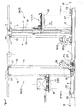
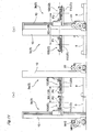
- this article storage facility includes two article storage racks 1 which are installed to be spaced apart from each other such that the side of one of the racks where articles are brought into and taken out of faces the side of the other of the racks where articles are brought into and taken out of, and stacker cranes 3 which move in a travel passage 2 (which corresponds to the travel path) formed between the two article storage racks 1.
- a carry in and out portion 5 for receiving and supporting the article 4 carried in from the outside and for receiving and supporting articles 4 which are being retrieved from the article storage rack 1 and taken out to the outside.
- Each article storage rack 1 includes a plurality of front and back pairs of vertical support columns 1a with each pair separated from one another in the rack lateral width direction and a plurality of vertically-spaced shelf boards 1b connecting neighboring columns 1a in the rack lateral width direction.
- Each shelf board 1b is configured to receive and support an article 4 such that a part of the article 4 projects toward the front in the rack fore and aft direction.
- the shelf boards 1b are configured such that a plurality of articles 4 are received and supported with the plurality of articles 4 being lined up in the rack lateral width direction.
- the storage units 6 of the article storage rack 1 are configured to store articles 4 with the articles 4 placed on and supported by the shelf boards 1b.
- the storage units 6 are provided on both sides of the travel passage 2 in the rack fore and aft direction (direction which intersects perpendicularly with the rack lateral width direction) and such that a plurality of them line up in the vertical direction and in the right and left direction or the lateral direction.
- a first stacker crane 3a (hereinafter referred to as No. 1 crane 3a) which moves on one side in the rack fore and aft direction with respect to the center of the travel passage 2, and a second stacker crane 3b (hereinafter referred to as No.2 crane 3b) which moves on the other side in the rack fore and aft direction.
- Two lower rails 7 (which correspond to the travel guide rails) are laid in parallel along the rack lateral width direction on the floor surface of the travel passage 2, and two upper rails 8 are arranged in parallel along the rack lateral width direction above the travel passage 2.
- the ones on one side in the rack fore and aft direction are for allowing the No. 1 crane 3a to travel along the travel passage 2
- the ones on the other side in the rack fore and aft direction are for allowing the No. 2 crane 3b to travel along the travel passage 2.
- Each of the No. 1 crane 3a and No. 2 crane 3b is configured to be able to travel in the travel passage 2 in both directions over the total length of the article storage rack 1 in the rack lateral width direction and the locations of the carry in and out portions 5.
- No. 1 crane 3a and No. 2 crane 3b are described next.
- No. 1 crane 3a and No. 2 crane 3b are identical in structure and differ only in that they are oriented in the opposite direction in the travel passage 2. Accordingly, they will be referred to as stacker cranes 3 when describing the same structures without distinguishing between the No. 1 crane 3a and No. 2 crane 3b.
- the stacker crane 3 includes a traveling carriage 9 which can travel along the lower rail 7, and a vertically movable platform 11 which can be raised and lowered along a vertical movement guiding mast 10 arranged vertically on the traveling carriage 9.
- the vertically movable platform 11 is provided with an article transfer device 12 which can transfer articles 4 to and from the storage units 6 and the carry in and out portion 5.
- the vertically movable platform 11 and the article transfer device 12 constitute the vertically movable body UD.
- the traveling carriages 9 are formed to have a flat shape which is long in the rack lateral width direction, and are configured to travel in the travel passage 2 such that the traveling carriage 9 of the No. 1 crane 3a and the traveling carriage 9 of the No. 2 crane 3b can pass each other.
- the vertical movement guiding mast 10 of No. 1 crane 3a is provided to the traveling carriage 9 at a location displaced toward one side (direction toward the closer one of the racks) in the rack fore and aft direction
- the vertical movement guiding mast 10 of No. 2 crane 3b is provided to the traveling carriage 9 at a location displaced toward the other side (direction toward the closer one of the racks) in the rack fore and aft direction.
- the vertically movable platform 11 of No. 1 crane 3a extends from the vertical movement guiding mast 10 of the No. 1 crane 3a in the rack fore and aft direction and is cantilevered to the vertical movement guiding mast 10 such that it does not contact the vertical movement guiding mast 10 of No. 2 crane 3b
- the vertically movable platform 11 of No. 2 crane 3b also extends from the vertical movement guiding mast 10 of the No. 2 crane 3b in the rack fore and aft direction and is cantilevered to the vertical movement guiding mast 10 such that it does not contact the vertical movement guiding mast 10 of No. 1 crane 3a.
- No. 1 crane 3a and No. 2 crane 3b are configured to travel in the travel passage 2 in both directions such that they can pass each other.
- the vertical movement guiding mast 10 is formed to have a flat shape which is long in the rack lateral width direction, and is arranged vertically at one end side of the traveling carriage 9 in the rack lateral width direction.
- the vertical movement guiding mast 10 is provided to the traveling carriage 9 to stand vertically at the position offset from the lower rail 7 toward the article storage rack 1 as viewed in the rack lateral width direction.
- the vertical movement guiding mast 10 is configured such that its upper end is higher than the lower end portion of the upper rail 8.
- Two upper guide rollers 14 are provided at the upper end portion of the vertical movement guiding mast 10 such as to hold the upper rail 7 between the guide rollers 14 and are supported by the support 13 extending in the rack fore and aft direction. Movement of the stacker crane 3 in the rack fore and aft direction is restricted by the contact between these two upper guide rollers 14 and the upper rails 7.
- the vertically movable platform 11 fittingly engages with two rails 15 for vertical movement provided in the vertical movement guiding mast 10 to be able to move up and down in the vertical direction by means of the single vertical movement guiding mast 10.
- One end of a chain 16 for raising and lowering the vertically movable platform 11 is connected to the vertically movable platform 11.
- the raising and lowering chain 16 is wound around an upper sprocket 17 provided in the upper portion of the vertical movement guiding mast 10, wound around a lower sprocket 18 provided in the traveling carriage 9, and its other end is connected to the vertically movable platform.
- a drive sprocket 20 rotated by a vertical movement electric motor MV is provided to engage the raising and lowering chain 16.
- the vertically movable platform 11 is configured to be raised and lowered by the movement of the raising and lowering chain 16 in its longitudinal direction by the forward and reverse rotations of the vertical movement electric motor MV. It is also possible to use other known material, such as a wire in place of the raising and lowering chain 16.
- the travel wheels 21 which can rotate on the lower rail 7 are provided to the traveling carriage 9.
- One of the pair of back and front travel wheels 21 is configured to be a drive wheel 21a rotated by the travel electric motor MH, and the other wheel is configured to be a free-rotating wheel 21b which is freely rotatable.
- a first laser vertical range finder 23 is provided to the traveling carriage 9 of No. 1 crane 3a (second vertical laser range finder 27 for No. 2 crane 3b) for detecting the vertical position of the vertically movable body UD in the vertical movement path.
- the first laser vertical range finder 23 is configured to measure the distance to the vertically movable body UD by emitting a light (laser light) -- for finding the distance -- along the vertical direction toward the first vertical movement reflector 24 provided to the vertically movable platform 11 (second vertical movement reflector 28 for No. 2 crane 3b), and receiving the light reflected by the vertical movement reflector 24.
- the first laser vertical range finder 23 is configured to detect the vertical position of the vertically movable body UD from the distance measured to the vertically movable body UD.
- the first laser vertical range finder 23 and the second laser vertical range finder 27 constitute the pair of vertical position detection means. It is possible to use a known sensor as the vertical position detection means, such as a rotation sensor attached to the vertically movable body UD for measuring rotation of a gear engaged to the linear gear teeth or a rack provided in the vertical movement guiding mast 10, a rotation sensor which measures rotation of a gear that engages the chain 16 for the vertical movement, or a contact sensor attached to the vertically movable body UD.
- a first laser travel range finder 25 (second laser travel range finder 29 for No. 2 crane 3b) which detects the travel position of the traveling carriage 9 in the travel passage 2 is provided in the traveling carriage 9.
- a first laser travel range finder 25 is configured to measure the distance between the first laser travel range finder 25 (second laser travel range finder 29 for No. 2 crane 3b) and the traveling carriage 9 in the rack lateral width direction by emitting a distance measuring light (laser light) towards a first travel movement reflector 26 (second travel movement reflector 30 for No. 2 crane 3b) along the rack lateral width direction, receiving the light reflected by the first travel movement reflector 26, and by measuring the elapsed time.
- the first travel movement reflector 26 is provided on the ground side and at one end of the travel passage 2, and its location is defined to be the reference position for detecting the travel position of the traveling carriage 9 of the No. 1 crane 3a.
- the first laser travel range finder 25 is configured to measure the distance from the reference position which is the installation position of the first travel movement reflector 26 to the traveling carriage 9 of the No. 1 crane 3a to detect the travel position of the traveling carriage 9 of No. 1 crane 3a.
- the second travel movement reflector 30 is provided at the end that is on the opposite side of the travel passage 2 from where the first travel movement reflector 26 is provided and on the ground side, and its location is defined to be the reference position for detecting the travel position of the traveling carriage 9 of the No. 2 crane 3b.
- the second laser travel range finder 29 is configured to measure the distance from the reference position which is the installation position of the second travel movement reflector 30 to the traveling carriage 9 of the No. 2 crane 3b to detect the travel position of the traveling carriage 9 of No. 2 crane 3b.
- the first laser travel range finder 25 and the second laser travel range finder 29 correspond to the pair of travel position detection means.
- the article transfer device 12 includes a support-and-transport portion which supports and transports an article 4 in an article transfer direction which is along the rack fore and aft direction, a base platform which supports this support-and-transport portion for movement in the article transfer direction, and projecting and retracting actuating means for retracting the support-and-transport portion to a retracted position pulled back to the base platform in the article transfer direction and for projecting the support-and-transport portion to a projected position projected outwardly from the base platform 28 in the article transfer direction. It is also possible to use a known structure with an articulated robot arm as the article transfer device 12.
- the ground side controller H as control means to control the operation of the No. 1 crane 3a and No. 2 crane 3b is provided.
- the various control means, controllers, or other members with control functions described in the present specifications have one or more CPU, memory, and a communication unit, and store the algorithms which execute the functions described in the specification.
- the ground side controller H is configured to communicate with each of the laser travel range finder and laser vertical range finder and with each of a servo amplifier for traveling and a servo amplifier for vertical movement provided to the stacker crane 3.
- the communication between the ground side controller H and each of the laser range finders and each servo amplifier in the stacker crane 3 is performed by the wireless communication devices 19, 22 which utilize infrared light.
- the wireless communication devices 19, 22 are described next, taking as an example the No. 1 crane wireless communication device 19 which performs infrared communication between the No. 1 crane 3a and the ground side controller H.
- No. 1 crane wireless communication device 19 consists of a ground side communication unit 19a which is installed in the ground side and at an end of the travel passage 2, and which is connected by wire with the ground side controller H, and a terminal communication unit 19b which is installed in the traveling carriage 9 of the No. 1 crane 3a and which is connected by wire to the laser vertical range finder 23, the laser travel range finder 25, the servo amplifier for vertical movement SV1, and the servo amplifier for traveling SH1 of the No. 1 crane 3a.
- Each of the ground side communication unit 19a and the terminal communication unit 19b is provided with an infrared transmitter and a receiver. And the ground side communication unit 19a transmits carrier signals in the infrared light modulated by baseband signals conveying various control information including the target travel position information and the target vertical position information, etc. for No. 1 crane 3a to the terminal communication unit 19b.
- the terminal communication unit 19b demodulates the received infrared signal and outputs various control information, including the target travel position information, target vertical position information, etc., to the servo amplifier for the vertical movement SV1, and the servo amplifier for traveling SH1.
- the terminal communication unit 19b transmits carrier signals in the infrared light modulated by baseband signals conveying the vertical position information of the vertically movable body UD which is detected by the laser vertical range finder 23, and the travel position information of the traveling carriage 9 of the No. 1 crane 3a which is detected by the laser travel range finder 25, to the ground side communication unit 19a.
- the ground side communication unit 19a demodulates the received infrared signal, and outputs the vertical position information of the vertically movable body UD of No. 1 crane 3a and the travel position information of the traveling carriage 9 of No. 1 crane 3a to the ground side controller H.
- the ground side controller H can control the operation of the No. 1 crane 3a by performing the two-way communication between the ground side communication unit 19a and the terminal communication unit 19b.
- the ground side controller H can control the operation of the No. 2 crane 3b by performing the two-way communication between the ground side communication unit 22a and the terminal communication unit 22b of the No. 2 crane wireless communication device 22.
- the modulation and demodulation cycle of the wireless communication devices 19, 22 is sufficiently shorter than the control cycle of the ground side controller H.
- the ground side controller H is configured to control the travel operation of the traveling carriages 9 as well as the vertical movement operation of the vertically movable bodies UD of the No. 1 crane 3a and No. 2 crane 3b to move the article transfer device 12 on the front side of the rack to the target stop position set in advance for each of the storage units 6 or the carry in and out portion 5 in order to move the article transfer device 12 to the storage unit 6 or the carry in and out portion 5 as the transport origin or a transport destination, which is specified by the operation command.
- the target stop position is set at a higher position when unloading (that is, handing over) an article 4 to a storage unit 6 or the carry in and out portion 5 than when picking up (that is, receiving) an article 4 from a storage unit 6 or the carry in and out portion 5.
- the ground side controller H is configured to control the operation of the projecting and retracting actuating means and the support-and-transport portion of the article transfer device 12 to transfer the article between the article transfer device 12 and the target storage units 6 or the carry in and out portions 5 with the article transfer device 12 positioned at the target stop position.
- the stacker crane 3 is controlled by the ground side controller H based on the operation command to perform an storage operation and a retrieval operation in which the stacker crane 3 performs an empty transporting operation (which corresponds to the article transporting operation), in which the article transfer device 12 travels carrying and supporting no articles 4, to the transport origin specified by the operation command and, when the transport origin is reached, performs a pick-up transfer operation in which an article 4 is picked up from the transport origin, then, performs an actual transporting operation (which corresponds to the article transporting operation) in which the article transfer device 12 travels to the transport destination carrying and supporting an article 4, and, when the transport destination is reached, performs an unloading transfer operation in which the article 4 is unloaded to the transport destination.
- a return-to-origin operation may be performed in which the stacker crane 3 is returned to the home position HP to wait for a command.
- the home position is set to be the position where the traveling carriage 9 is located at one end in the travel passage 2 in the rack lateral width direction, and the vertically movable body UD is located in the vertical movement lower limit position. See Fig. 1 .
- the ground side controller H searches for a stacker crane to which no article transporting operation is assigned (hereafter referred to as unassigned crane). If both of the No. 1 crane 3a and No. 2 crane 3b are cranes with no assignment or unassigned cranes, the stacker crane closer to the transport origin is set to be the stacker crane in charge of carrying out the operation command (hereafter referred to as an assigned crane) based on the transport origin position information specified by the operation command and on the current positions of the No. 1 crane 3a and No. 2 crane 3b. If either of the No. 1 crane 3a and No.
- 2 crane 3b is an unassigned crane
- the unassigned crane is set to be the assigned crane which takes charge of carrying out the operation command. If both of No. 1 crane 3a and No. 2 crane 3b are assigned cranes, then when either of the stacker cranes becomes an unassigned crane, the unassigned crane is set to be an assigned crane which takes charge of carrying out the operation command. If operation commands are issued one after another when both of the No. 1 crane 3a and No. 2 crane 3b are assigned cranes, the operation command information is stored, and when an assigned crane becomes available, the cranes are assigned sequentially for the operation commands which are stored earlier.
- the ground side controller H selects the assigned crane, it transmits the target vertical position information and the target vertical position information to the assigned crane at every control cycle (10 ms in the present embodiment), to control the article transporting operation of the assigned crane.
- the control of the article transporting operation of the stacker crane 3 by the ground side controller H is described next.
- the ground side controller H issues to the No. 1 crane 3a and No. 2 crane 3b the target travel position information for respective traveling carriages of No. 1 crane 3a and No. 2 crane 3b, and the target vertical position information for each of the vertically movable body of the No. 1 crane 3a and No. 2 crane 3b at every control cycle to control the operation of the stacker crane 3 in order to move the article transfer device 12 from the operation starting position to the operation end position.
- the operation starting position is the transport origin for the operation command if the article transporting operation is the actual transporting operation, and is the transport destination for the operation command that was last carried out by the stacker crane if it is the empty transporting operation or the return-to-origin operation.
- the operation end position is the transport destination for the operation command if the article transporting operation is the actual transporting operation, and is the transport origin for the operation command if it is an empty transporting operation, and is the home position if it is the return-to-origin operation.
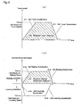
- the target travel position information is the target values for the travel position at every control cycle to control the change of the travel position of the traveling carriage 9 so that it carries out the speed change which follows the travel speed change pattern (see Fig. 5 (a) ) which allows to cover the travel distance DH that is required to travel from the operation starting position to the operation end position in the shortest time possible under the restrictions of the set travel acceleration aH, the set maximum travel speed VHmax, and the set travel deceleration BH.
- the target vertical position information for example, for a raising operation from the operation starting position to the operation end position, is the target values for the vertical position at every control cycle to control the change of the vertical position of the vertically movable body UD so that it carries out the speed change which follows the vertical movement speed change pattern (see Fig. 5 (b) in which the one shown with a solid line is the vertical movement speed change pattern for the raising operation) which allows to cover the vertical distance DV that is required to travel from the operation starting position to the operation end position in the shortest time possible under the restrictions of the set raising acceleration ⁇ up, the set maximum raising speed Vupmax, and the set vertical deceleration ⁇ up.
- the target vertical position information is the target values for the vertical position at every control cycle to control the change of the vertical position of the vertically movable body UD so that it carries out the speed change which follows the vertical movement speed change pattern (see Fig. 5 (b) in which the one shown with the dotted line is the vertical movement speed change pattern for the lowering operation) which allows to cover the necessary vertical distance DV in the shortest time possible under the restrictions of the set lowering acceleration adw, the set maximum lowering speed Vdwmax, and the set vertical deceleration ßdw.
- the travel position information for the traveling carriage 9 of the No. 1 crane 3a from the first laser travel range finder 25 and the vertical position information for the vertically movable body UD of the No. 1 crane 3a from the first laser vertical range finder 23 are transmitted from the No. 1 crane 3a to the ground side controller H at every control cycle through the No. 1 crane wireless communication device 19. And the ground side controller H updates and generates the target travel position information and the target vertical position information for the No. 1 crane 3a based on the travel position information for the traveling carriage 9 of the No. 1 crane 3a and the vertical position information for the vertically movable body UD of the No. 1 crane 3a such that the traveling carriage 9 of No.
- the travel position information for the traveling carriage 9 of the No. 2 crane 3b from the second laser travel range finder 29 and the vertical position information for the vertically movable body UD of the No. 2 crane 3b from the second laser vertical range finder 27 are transmitted from the No. 2 crane 3b to the ground side controller H at every control cycle through the No. 2 crane wireless communication device 22.
- the ground side controller H updates and generates the target travel position information and the target vertical position information for the No. 2 crane 3b based on the travel position information for the traveling carriage 9 of the No. 2 crane 3b and the vertical position information for the vertically movable body UD of the No. 2 crane 3b such that the traveling carriage 9 of the No.
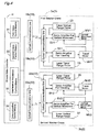
- the ground side controller H includes first crane control means 31, second crane control means 32, interference avoidance control means 33, and communication control means 34 consisting of computer programs.
- the travel position information for the traveling carriage 9 detected by the first laser travel range finder 25 and the motor rotational speed information from the rotary encoder which is provided to the travel motor MH1 are input to the servo amplifier for traveling SH1, and the vertical position information for the vertically movable body UD detected by the first laser vertical range finder 23 and the motor rotational speed information from the rotary encoder which is provided to the vertical movement motor MV1 are input to the servo amplifier for the vertical movement SV1.
- These servo amplifiers operate in the position control mode.
- the servo amplifier for traveling SH1 controls the motor actuating output to the travel motor MH1 of the No. 1 crane 3a such that the travel position of the traveling carriage 9 detected by the first laser travel range finder 25 coincides with the set target position.
- servo amplifier for the vertical movement SV1 controls the motor actuating output to the vertical movement motor MV1 of the No. 1 crane 3a such that the vertical position of the vertically movable body UD detected by the first laser vertical range finder 23 coincides with the set target position.
- the first crane control means 31 generates the target travel position information as the target position information for the servo amplifier for traveling SH1 which operates in position control mode at every control cycle based on the target travel position information transmitted from the No. 1 crane 3a, such that the travel position of the traveling carriage 9 coincides with the target travel position.
- the generated target travel position information is outputted to the ground side communication unit 19a of the No. 1 crane wireless communication device 19 from the communication port which the communication control means 34 controls. Thereby, the travel motor MH1 of No. 1 crane 3a rotates such that the traveling carriage 9 is located at the travel position which the target travel position information indicates.
- the first crane control means 31 generates the target travel position information as the target position information for the servo amplifier for vertical movement SV1 which operates in position control mode at every control cycle based on the target vertical position information transmitted from the No. 1 crane 3a, such that the vertical position of the vertically movable body UD coincides with the target vertical position.
- the generated target vertical position information is outputted to the ground side communication unit 19a of the No. 1 crane wireless communication device 19 from the communication port which the communication control means 34 controls. Thereby, the vertical movement motor MV1 of the No. 1 crane 3a rotates such that the vertically movable body UD is located at the vertical position indicated by the target vertical position information.
- the ground side controller H transmits the target travel position information and the target vertical position information to the servo amplifier for traveling SH1 of the No. 1 crane 3a and the servo amplifier for vertical movement SV1 at every control cycle, the traveling carriage 9 of the No. 1 crane 3a travels such that it is located at the travel position indicated by the target travel position information, and the vertically movable body UD of the No. 1 crane 3a is raised and lowered such that it is located at the vertical position indicated by the target vertical position information.
- the ground side controller H similarly transmits the target travel position information and the target vertical position information to the servo amplifier for traveling SH2 of the No. 2 crane 3b and the servo amplifier for vertical movement SV2 at every control cycle, the traveling carriage 9 of the No. 2 crane 3b travels such that it is located at the travel position indicated by the target travel position information, and the vertically movable body UD of the No. 2 crane 3b is raised and lowered such that it is located at the vertical position indicated by the target vertical position information.
- ground side controller H The control operation of the ground side controller H is described next.
- the ground side controller H manages the travel position of the traveling carriage 9 of the stacker crane 3 and the vertical position of the vertically movable body UD by means of the representative position P of the stacker crane 3 (see Fig. 10 ) which is the center in the rack lateral width direction (the direction of the path of the travel passage 2 or the travel direction of the traveling carriage 9) of the article support surface in the support-and-transport portion of the article transfer device 12 as seen in the rack back-and-front direction in the travel passage 2.
- the travel position of the traveling carriage 9 is managed as the x-coordinate of the representative position P
- the vertical position of the vertically movable body UD is managed as the y-coordinate of the representative position P in a hypothetical rectangular coordinate system located on the front side of the rack with the rack lateral width direction (the travel direction of the traveling carriage 9) taken as the horizontal axis (x-axis) and the vertical direction of the rack (the vertical movement direction of the vertically movable body UD) taken as the vertical axis (y-axis).
- this hypothetical rectangular coordinate system is defined to be the coordinates of the representative position P when the traveling carriage 9 is located at one end of the travel passage 2, and when the vertically movable body UD is located in the vertical movement lower limit position, that is, when the stacker crane 3 is at the home position HP.
- the travel position of the traveling carriage 9 and the vertical position of the vertically movable body UD will be expressed in terms of the crane center coordinates P (x, y), and the crane center coordinates of the No. 1 crane 3a are expressed as P1 (x1, y1), and the crane center coordinates of No. 2 crane 3b are expressed as P2 (x2, y2). That is, the travel position of the traveling carriage 9 of the No. 1 crane 3a is expressed as x1, and the vertical position of the vertically movable body UD of No. 1 crane 3a is expressed as yl. And the travel position of the traveling carriage 9 of the No. 2 crane 3b is expressed as x2, and the vertical position of the vertically movable body UD of No. 2 crane 3b is expressed as y2. And, the crane center coordinates P (x, y) may sometimes simply be referred to as the position of the stacker crane 3.
- the control means one or both of the first crane control means 31 and the second crane control means 32
- the control means of the assigned crane generates at # 01 the target travel position information based on the travel speed pattern for the article transporting operation and the target vertical position information based on the vertical movement speed pattern for the article transporting operation, which patterns are determined from the operation starting position and the operation end position of the article transporting operation for the assigned crane, and stores them in the output buffer.
- the interference avoidance control means 33 determines whether the No. 1 crane 3a and No. 2 crane 3b are at mutually proximate positions where No. 1 crane 3a and No. 2 crane 3b are predicted to mutually interfere or collide. In this process, assuming that the traveling carriage 9 of the No. 1 crane 3a and the traveling carriage 9 of the No.
- Figs. 7 (b) and (c) there are cases as shown in Figs. 7 (b) and (c) in addition to Fig. 7 (a) , where the No. 1 crane hypothetical braking range VBW1 and No. 2 crane hypothetical braking range VBW2 overlap at least in the part.
- Fig. 7 (a) shows a case where the respective hypothetical braking ranges of No. 1 crane 3a and No. 2 crane 3b overlap when both of No. 1 crane 3a and No. 2 crane 3b perform the article transporting operation as assigned cranes, and when they are traveling in directions in which they face each other.
- Fig. 7 (b) shows a case where the respective hypothetical braking ranges of No. 1 crane 3a and No. 2 crane 3b overlap when both of No. 1 crane 3a and No.
- FIG. 7 (c) shows a case where the No. 2 crane 3b is located in the hypothetical braking range VBW1 of the No. 1 crane 3a when only No. 1 crane 3a is performing the article transporting operation as an assigned crane, and when No. 2 crane 3b is in the standby state as an unassigned crane, that is, when the operation speed V2 of No. 2 crane 3b is zero.
- the first crane control means 31 of the ground side controller H computes the travel speed Vx1 of the traveling carriage 9 of No. 1 crane 3a from the time rate of change of the detected information from the first laser travel range finder 25, and computes the vertical movement speed Vy1 of the vertically movable body UD of No. 1 crane 3a from the time rate of change of the detected information from the first laser travel range finder 23, and because the second crane control means 32 of the ground side controller H computes the travel speed Vx2 of the traveling carriage 9 of No. 2 crane 3b from the time rate of change of the detected information from the second laser travel range finder 29, and computes the vertical movement speed Vy2 of the vertically movable body UD of No.
- the interference avoidance control means 33 can refer to the travel speed information for the traveling carriage 9 of the No. 1 crane 3a which the first crane control means 31 computes, and the travel speed information for the traveling carriage 9 of the No. 2 crane 3b which the second crane control means 32 computes in determining whether they are at the mutually proximate positions.
- step # 04 the communication control means 34 waits for the control timing before outputting the target travel position information and the target vertical position information for the assigned crane which the first crane control means 31 and the second crane control means 32 prepared in advance at # 01.
- the control proceeds to # 03 and the interference avoidance process is executed by the interference avoidance control means 33.
- the crane for the avoidance operation is selected as needed in the interference avoidance process and the target vertical position for the avoidance operation for the crane subject to the avoidance operation is computed.
- the target vertical position information stored in the output buffer by the first crane control means 31 and the second crane control means 32 at # 01 is overwritten and updated. Since the amount of calculation in this interference avoidance process is such that the calculation can be completed by the subsequent control timing, the control can be returned to # 04 by the subsequent control timing.
- the communication control means 34 outputs the target vertical position information stored in the output buffer for the avoidance operation for the crane for the avoidance operation and the target vertical position information similarly in the output buffer for the article transporting operation for the other stacker crane 3, to No. 1 crane 3a and No. 2 crane 3b at # 05.
- the interference avoidance process executed by the interference avoidance control means 33 is described next with reference to the flow chart shown in Fig. 8 .
- the No. 1 crane 3a and No. 2 crane 3b interfere, for example, when the coordinates of the operation end position P1e of the No. 1 crane 3a coincide with the coordinates of the operation end position of No. 2 crane 3b because the operation end positions of respective article transporting operation are the storage units 6 or the carry in and out portions 5 that are located to face each other across the travel passage 2, or when the operation end position is located in the area in the coordinate plane occupied by a structure, such as the motor cover of the other traveling carriage 9 in a standby state. Therefore, the verification process continues to be performed in the processes at or after # 12 to see if the interference between both cranes can occur.
- the area in the coordinate plane that is occupied by a structure such as the traveling carriage 9, the vertical movement guiding mast 10, and the vertically movable body UD of the stacker crane 3 is defined as the occupied area when the stacker crane 3 is located at the operation end position.
- the area in the coordinate plane that is occupied by a structure such as the traveling carriage 9, the vertical movement guiding mast 10, and the vertically movable body UD of the stacker crane 3 is defined as the occupied area when the stacker crane 3 is located at the stand-by position. As shown in Fig.
- the representative dimensions of each part with respect to the center at the crane center coordinates P (x, y) of the stacker crane 3 which is used to define the occupied area are stored in advance.
- the occupied width (XA+XB) in the x direction and the occupied height (YA+YB) in the y direction for the vertically movable body UD, and the occupied width (XE+XD) in the x direction and the occupied height (YC) in the y direction for the traveling carriage 9, etc. are defined with respect to the center at the crane center coordinates P(x, y).
- the existence of interference is determined at # 14 based on the interference evaluation value determined by the interference determination process at # 13. If the interference determination value is "0", the interference avoidance control means 33 will end the interference avoidance process without rewriting the target travel position information and the target vertical position information for the No. 1 crane 3a or No. 2 crane 3b in the output buffer to those for the avoidance operation. And the control of the ground side controller H returns to the main routine in Fig. 6 .
- interference evaluation value is "1" ⁇ "3" at # 14
- the control proceeds to # 15, and it is determined whether both of No. 1 crane 3a and No. 2 crane 3b are assigned cranes or only one is the assigned crane at the current control timing. If both are performing an article transporting operation as assigned cranes, the remaining operation time for each stacker crane 3 is computed at # 16. That is, the longer of the remaining travel operation time and the remaining vertical movement operation time to the operation end position P1e (x1e, y1e) for the No. 1 crane 3a is defined to be the remaining operation time for the No. 1 crane 3a.
- the remaining travel operation time is the time required to cover the remaining travel distance x1e-x1 from the current position P1 (x1, y1) of No.
- the remaining vertical movement operation time is the time required to cover the remaining vertical distance y1e-y1 from the current position P1(x1, y1) of No. 1 crane 3a to the operation end position P1e (x1e, y1e), and is computed based on the present operation speed V1 (Vx1, Vy1), the set raising acceleration ⁇ up or set lowering acceleration adw, the set raising deceleration ⁇ up or set lowering deceleration ßdw.
- the remaining operation time of No. 1 crane 3a and the remaining operation time of No. 2 crane 3b are compared at # 17 and the assigned crane with the longer remaining time is set as a crane subject to the avoidance operation. Therefore, the assigned crane with the shorter remaining transport time for an article transporting operation can proceed with the article transporting operation.
- the assigned crane with the longer remaining operation time for the article transporting operation waits at the move-out position computed at # 19 at least until the article transporting operation of the other assigned crane is completed and moves away from the operation end position for the article transporting operation.
- the control proceeds to # 18, and the unassigned crane is set as to be the crane subject to the avoidance operation. Therefore, the assigned crane which is in charge of an article transporting operation can proceed with the article transporting operation and the unassigned crane which is not in charge of the article transporting operation retreats from the operation end position for the article transporting operation for the other assigned crane to a move-out position computed at # 19.
- the ground side controller H is configured to perform the interference avoidance process by controlling one of the pair of stacker cranes 3. And, when the ground side controller H is causing only one of the pair of stacker cranes 3 to perform an article transporting operation as an assigned stacker crane, the ground side controller H is configured to perform the interference avoidance process by controlling the operation of the stacker crane 3 which is not performing the article transporting operation among the pair of stacker cranes 3.
- the ground side controller H when the ground side controller H is causing both of the pair of stacker cranes 3 to perform an individual article transporting operation as an assigned stacker crane, the ground side controller H is configured to perform the interference avoidance process by controlling the operation of the assigned stacker crane with the longer remaining operation time for the article transporting operation among the pair of stacker cranes 3.
- the move-out position for the crane which is subjected to the avoidance operation is determined depending on the value of the interference evaluation value obtained at # 13 such that the crane center coordinates P of the crane subjected to the avoidance operation is positioned outside the occupied area of the other stacker crane 3.
- the trajectory including the portion shown with the dashed line is the trajectory of the No. 1 crane 3a when it did not perform the interference avoidance operation but instead proceeded to the end of the article transporting operation.
- No. 1 crane 3a is set or selected as an assigned crane to be subjected to the avoidance operation.
- the ground side controller H is configured to perform the interference avoidance process in which the operations of the pair of stacker crane 3 are controlled to position the pair of traveling carriages 9 and the pair of vertically movable bodies UD in the non-interfering positions where the pair of stacker cranes 3 would not or will not interfere with each other, based on the detected information from the first laser travel range finder 25, the second laser travel range finder 29, the first laser vertical range finder 23, and the second laser vertical range finder 27, when respective travel positions of the pair of traveling carriages 9 are at the mutually proximate positions.
- the move-out position computed at # 19 is a position to which the stacker crane 3 subjected to the avoidance operation can actually be moved, or more specifically, whether the x-coordinate of the move-out position is within the travel passage 2. If the x-coordinate of the move-out position is within the travel passage 2, the move-out position is set as an operation end position to perform the avoidance operation on the crane subjected to the avoidance operation to move it to the move-out position, after which, the control leaves the interference avoidance process and returns to the main routine in Fig. 7 . Thus, at the subsequent control timings, the first crane control means 31 or the second crane control means 32 generates, at # 01 in Fig.
- information for the avoidance operation (the target travel position information and target vertical position information which should be outputted at the control timing in order to position the crane subjected to the avoidance operation in the move-out position) as the target travel position information and the target vertical position information for the crane subjected to the avoidance operation.
- the first crane control means 31 or the second crane control means 32 Because the operation end position has been determined, at the subsequent control timings, the first crane control means 31 or the second crane control means 32 generates information for the avoidance operation (the target travel position information and target vertical position information which should be outputted at the control timing in order to position the crane subjected to the avoidance operation in the operation end position determined by the contingent operation end position set process) as the target travel position information and the target vertical position information for the crane subjected to the avoidance operation. In so doing, the crane subjected to the avoidance operation performs a contingent article transporting operation which is not based on the operation command. In this way, the crane subjected to the avoidance operation can avoid interference with the other stacker crane by traveling toward an operation end position different from the move-out position computed before.
- the interference avoidance control means 33 derives the maximum vertical movement range Z which each vertically movable body UD can cover by being raised or lowered in the remaining time T from the time the travel positions of the traveling carriages 9 of the No. 1 crane 3a and No. 2 crane 3b become the mutually proximate positions until they reach the assumed interference travel positions in the processes at and subsequent to # 22. And the No. 1 crane 3a and No. 2 crane 3b are allowed to pass each other and move without interfering mutually by changing the vertical movement operation of the vertically movable body UD from the vertical movement operation for an article transporting operation from the time the travel position of each traveling carriage 9 reaches the mutually proximate position, except when the maximum vertical movement range Z for each traveling carriage 9 of No.
- the required separating distance y_CL is set to be the constant value "YA+YB" regardless of whether the article transfer device 12 is supporting an article 4 (whose height is less than YB).
- the assigned crane computes the maximum vertical movement range Z by which the vertically movable body UD can be raised or lowered in the remaining time T from the current control timing at # 22.
- the remaining time T is the amount of time from the time respective travel positions of the traveling carriages 9 of the No. 1 crane 3a and No. 2 crane 3b reach the mutually proximate positions until the time they reach the assumed interference travel positions at which the pair of vertically movable bodies are assumed to interfere each other when the traveling carriages 9 in the travel operations are decelerated at the set travel deceleration BH.
- the travel positions of the traveling carriages 9 are the assumed interference travel positions when each traveling carriage 9 of the No. 1 crane 3a and No. 2 crane 3b satisfies the relative travel positional relationship shown in Fig. 11 (b) , that is, the travel positional relationship where the x-coordinate x2 of the crane center coordinates P2 of the No. 2 crane 3b is greater than the x-coordinate x1 of the crane center coordinates P1 of the No. 1 crane 3a by the distance "XB+XB".
- the travel positions of respective traveling carriages 9 are the assumed interference travel positions when each traveling carriage 9 of the No. 1 crane 3a and No. 2 crane 3b satisfies the relative travel positional relationship shown in Fig. 11 (a) , that is, the travel positional relationship where the x-coordinate x1 of the crane center coordinates P1 of the No. 1 crane 3a is greater than the x-coordinate x2 of the crane center coordinates P2 of the No. 2 crane 3b by the distance "XA+XA".
- the maximum vertical movement range Z is estimated to be the greatest value possible, assuming a travel operation which requires the longest time after the cranes reach the mutually proximate positions until they reach the assumed interference travel positions among the travel operations for an article transporting operation.
- interference avoidance control means 33 determines that the interference non-occurring state exists in which the pair of stacker cranes do not interfere with each other if the maximum vertical movement range Z1 of the vertically movable body UD of the No. 1 crane 3a and the maximum vertical movement range Z2 of the vertically movable body UD of the No. 2 crane 3b do not mutually overlap because they are separated from each other by a distance greater than the required separating distance y_CL.
- the interference avoidance control means 33 determines that the interference non-occurring state exists in which the pair of stacker cranes do not interfere with each other, if the interference range -- which extends in both vertical directions along the vertical movement direction about the vertical position of the vertically movable body UD of the other stacker crane 3 by the required separating distance y_CL -- does not overlap with the maximum vertical movement range Z for the vertically movable body UD of the assigned crane.
- the interference upper limit position y2+y_CL which is the upper end of the interference range of the vertically movable body UD of the No. 2 crane 3b (i.e., when yT1_min>y2+y_CL holds), or, although not shown, if the vertical movement upper limit position yT1_max which is the upper end of the maximum vertical movement range Z1 of the vertically movable body UD of the No. 1 crane 3a is located below the interference lower limit position y2-y_CL which is the lower end of the interference range for the vertically movable body UD of the No. 2 crane 3b (i.e., when yT1_max ⁇ y2-y_CL holds) at the current control timing.
- the interference avoidance control means 33 ends the interference avoidance process without rewriting the target vertical position information for the No. 1 crane 3a and the No. 2 crane 3b with that for the avoidance operation and the control of the ground side controller H is returned to the main routine in Fig. 6 .
- the ground side controller H is configured to control the vertical movement operations of the pair of vertically movable body UD such as to perform an article transporting operation without controlling the vertical movements of the pair of vertically movable body UD using the interference avoidance process if it is determined that the interference non-occurring state exists, and so as to perform the article transporting operation by controlling the pair of vertically movable body UD by the interference avoidance process if it is determined that the interference non-occurring state does not exist in the interference avoidance process.
- the processes at # 24 - # 26 are executed to assign one of the No. 1 crane 3a and the No. 2 crane 3b as the crane to be subjected to the avoidance operation. Since the processes at # 24 - # 26 are identical to the processes at # 16 - # 18, descriptions for these steps are omitted.
- an avoidance vertical position calculation process is executed by the interference avoidance control means 33 to generate avoidance vertical position information for raising and lowering the vertically movable body UD of the subject crane in the vertical movement operation for the avoidance operation at # 28.
- the interference avoidance control means 33 overwrites the existing information in the output buffer with the avoidance vertical position information, obtained in this calculation process for the crane to be subjected to the avoidance operations, as the target vertical position information for the stacker crane, it ends the interference avoidance process, and the control of the ground side controller H is returned to the main routine in Fig. 7 .
- the avoidance vertical position calculation process is described next with reference to the flow chart shown in Fig. 13 . It is determined at # 201 whether the vertical position of the vertically movable body UD of the crane subjected to the avoidance operation at the current control timing is closer to the vertical movement upper limit position yT_max which is the upper end of the maximum vertical movement range of the other stacker crane 3, or to the vertical movement lower limit position yT_min which is the lower end of the range. If it is closer to the vertical movement upper limit position yT_max, the control proceeds to step # 202, and the target vertical position of the vertically movable body UD of the crane subjected to the avoidance operation is set to yT_max+y_CL.
- step # 203 the target vertical position of the vertically movable body UD of the crane subjected to the avoidance operation is set to yT_min-y_CL.
- the target vertical position of the vertically movable body UD of the No. 2 crane 3b is set to yT_max+y_CL if the vertical position y2 of the vertically movable body UD of No.
- any interference between the No. 1 crane 3a and the No. 2 crane 3b can be avoided because the stacker crane 3 subjected to the avoidance operation performs a travel operation and a vertical movement operation for avoiding interference in which each vertically movable body UD is raised or lowered to the vertical positions for passing each other which are spaced apart in the vertical direction by a distance greater than or equal to the required separating distance y_CL which is defined to be a separating distance which allows the No. 1 crane 3a and No. 2 crane 3b to pass each other without interfering each other. That is, the ground side controller H is configured to execute or perform the interference avoidance vertical movement process as an interference avoidance process.
- Fig. 16 (a) if only the No. 1 crane 3a, as an assigned crane, is performing an article transporting operation from the operation starting position P1s to the operation end position P1e, and if No. 2 crane 3b is stopped in the standby state as an unassigned crane, the No. 2 crane 3b which is the unassigned crane is determined to be the crane to be subjected to the avoidance operation when the travel positions of the traveling carriage 9 of the No. 1 crane 3a and the No. 2 crane 3b reach the mutually proximate positions; and, the vertically movable body UD of the No.
- 2 crane 3b performs a vertical movement operation for the avoidance operation to the vertical position P2n (x2, y2n), which is changed only in the y coordinate from the standby position P2 (x2, y2), for passing each other as a non-interfering position to avoid any interference between the No. 1 crane 3a and No. 2 crane 3b.
- No. 2 crane 3b with the longer remaining operation time is set or determined to be the crane for the avoidance operation when the travel position of the traveling carriage 9 of the No. 1 crane 3a and No. 2 crane 3b reach the mutually proximate positions; and, any interference between the No. 1 crane 3a and No. 2 crane 3b is avoided by causing the vertically movable body UD of No.
- the trajectory containing a portion shown with a dotted line is one in which the No. 2 crane 3b performs only the vertical movement operation for an article transporting operation, and not the vertical movement operation for avoiding interference.
- the interference avoidance process including the mutual avoidance vertical movement process performed by the interference avoidance control means 33 is described next with reference to the flow chart shown in Fig. 17 . Since the steps # 1 to # 23 in Fig. 17 are identical to those in Fig. 8 , descriptions for these steps are omitted here.
- Fig. 17 if it is not determined that the interference non-occurring state exists at # 23, the control proceeds to # 24, and the interference avoidance control means 33 executes the mutual avoidance vertical position calculation process to generate the avoidance vertical position information for each vertically movable body UD for raising or lowering both of the vertically movable bodies UD in the vertical movement operation for the avoidance operation.
- both of the pair of vertically movable bodies UD are raised and lowered by the vertical movement operation for avoiding interference, which is different from a vertical movement operation for an article transporting operation, to raise or lower the vertically movable body UD of the No. 1 crane 3a and the vertically movable body UD of the No. 2 crane 3b to the vertical positions for passing each other which are separated form each other in the vertical direction by a distance greater than or equal to the required separating distance y_CL which is defined to be a separating distance that allows the pair of stacker cranes 3 to pass each other without interfering with each other.
- the ground side controller H is configured to perform the mutual avoidance vertical movement process in this manner.
- the mutual avoidance vertical position calculation process is described next with reference to the flow chart in Fig. 18 .
- the difference G12 between the vertical movement upper limit position yT1_max in the maximum vertical movement range Z1 for the vertically movable body UD of the No. 1 crane 3a and the vertical movement lower limit position yT2_min in the maximum vertical movement range Z2 for the vertically movable body UD of the No. 2 crane 3b is calculated at # 301.
- the difference G21 between the vertical movement lower limit position yT1_min in the maximum vertical movement range Z1 about the vertically movable body UD of No. 1 crane 3a and the vertical movement upper limit position yT2_max in the maximum vertical movement range Z2 about the vertically movable body UD of No. 2 crane 3b is calculated at # 302.
- G12 and G21 are compared at # 303, and respective target vertical positions for the No. 1 crane 3a and the No. 2 crane 3b are computed based on the greater of the vertical position differences at # 304 and # 305. That is, "Yes” is taken at # 303 if G12 is larger than G21, and the control proceeds to # 304 and, the target vertical position of the vertically movable body UD of the No. 1 crane 3a is set to yT1_max - (G12-y_CL) / 2, and the target vertical position of the vertically movable body UD of the No. 2 crane 3b is set to yT2_min + (G12-y_CL) /2.
- the vertical movement operations for the pair of vertically movable bodies UD are controlled such as to secure the required separating distance y_CL by the vertical movement operations of both of the No. 1 crane 3a and the No. 2 crane 3b. Therefore, because the amount of vertical movement operations for avoiding interference, that each of the vertically movable bodies UD of No. 1 crane 3a and No. 2 crane 3b needs to cover, is evenly distributed between the two, the amount by which the No. 1 crane 3a and No.
- the vertically movable bodies UD can be raised or lowered the vertical positions for passing which are separated from each other by the required separating distance in the vertical movement direction as soon after the travel position of each of the traveling carriages 9 of the No. 1 crane 3a and No. 2 crane 3b reaches the mutually proximate position as possible.
- the value obtained by subtracting the required separating distance y_CL from the difference G12 between the vertical positions is divided by 2 and the position lower by the divided value than the vertical movement upper limit position yT1_max which is the upper end of the maximum vertical movement range Z1 of the No. 1 crane 3a is set to be the target vertical position for the vertically movable body UD of the No. 1 crane 3a, and the position higher by the divided value than the vertical movement lower limit position yT2_min which is the lower end of the maximum vertical movement range Z2 of No. 2 crane 3b is set to be the target vertical position for the vertically movable body UD of No. 2 crane 3b.
- both of the vertically movable bodies UD can be raised or lowered accurately to the vertical positions for passing each other, minimizing the unnecessary vertical movements.
- the vertically movable bodies UD of the No. 1 crane 3a and No. 2 crane 3b perform the vertical movement operations for the avoidance operation to the vertical positions for passing each other (P2n for No. 2 crane 3b), when the travel positions of the traveling carriage 9 of No. 1 crane 3a and No. 2 crane 3b reach the mutually proximate positions, to avoid any interference between No. 1 crane 3a and No. 2 crane 3b.
- the trajectory containing a portion shown with a dotted line in the drawing is one in which the No. 1 crane 3a performs only the vertical movement operation for an article transporting operation, and not the vertical movement operation for avoiding interference.
- both of the No. 1 crane 3a and No. 2 crane 3b are performing the article transporting operations as assigned cranes from the operation starting positions P1s, P2s to the operation end positions P1e, P2e, then both of the vertically movable bodies UD of the No. 1 crane 3a and No. 2 crane 3b perform vertical movement operations that are different from the vertical movement operation in an article transporting operation to move vertically to be located at the vertical positions for passing each other when the travel positions of the traveling carriages 9 of the No. 1 crane 3a and No. 2 crane 3b reach the mutually proximate positions to avoid any interference between the No. 1 crane 3a and No. 2 crane 3b.
- the trajectories containing a portion shown with a dotted line in the drawing are ones in which the No. 1 crane 3a and No. 2 crane 3b perform only the vertical movement operation for an article transporting operation, and not the vertical movement operation for avoiding interference.
- the ground side controller H is configured to perform the interference avoidance vertical movement process in which the vertical movement operations of the vertically movable bodies UD of the pair of stacker crane 3 are controlled based on the detected information from the first laser travel range finder 25, the second laser travel range finder 29, the first laser vertical range finder 23, and the second laser vertical range finder 27, to position the pair of vertically movable bodies UD at the non-interfering positions where the pair of stacker cranes 3 will not or would not interfere.
- the present invention is applicable to the article storage facility which utilizes stacker cranes.
Landscapes
- Engineering & Computer Science (AREA)
- Mechanical Engineering (AREA)
- Business, Economics & Management (AREA)
- Structural Engineering (AREA)
- Transportation (AREA)
- Automation & Control Theory (AREA)
- Geology (AREA)
- Life Sciences & Earth Sciences (AREA)
- Economics (AREA)
- Civil Engineering (AREA)
- Entrepreneurship & Innovation (AREA)
- Quality & Reliability (AREA)
- Tourism & Hospitality (AREA)
- Physics & Mathematics (AREA)
- General Business, Economics & Management (AREA)
- General Physics & Mathematics (AREA)
- Theoretical Computer Science (AREA)
- Strategic Management (AREA)
- Operations Research (AREA)
- Marketing (AREA)
- Human Resources & Organizations (AREA)
- Development Economics (AREA)
- Finance (AREA)
- Accounting & Taxation (AREA)
- Warehouses Or Storage Devices (AREA)
- Control And Safety Of Cranes (AREA)
Claims (21)
- Installation d'entreposage d'articles comprenant :un râtelier d'entreposage d'articles (1) ayant une pluralité d'unités d'entreposage (6) pour entreposer des articles (4), les unités d'entreposage (6) étant agencées dans une direction verticale et dans une direction latérale ; etune paire de ponts gerbeurs (3a, 3b) configurés pour se déplacer le long d'un chemin de déplacement (2) prévu sur un côté avant du râtelier d'entreposage d'articles (1) le long d'une direction de la largeur latérale du râtelier,chacun de la paire de ponts gerbeurs (3a, 3b) ayant un chariot roulant (9) guidé par un rail de guidage de déplacement (7) s'étendant le long du chemin de déplacement (2) et un corps mobile verticalement (UD) comportant une plateforme mobile verticalement (11) configurée pour être guidée en vue d'un mouvement vertical par un mât de guidage de mouvement vertical (10) prévu pour se trouver sur le chariot roulant (9) et un dispositif de transfert d'article (12) prévu sur la plateforme mobile verticalement (11) pour transférer un article (4) vers et en provenance des unités d'entreposage (6) ;une paire de moyens de détection de position de déplacement (25, 29) pour détecter des positions de déplacement respectives des chariots roulants (9) de la paire de ponts gerbeurs (3a, 3b) ;une paire de moyens de détection de position verticale (23, 27) pour détecter des positions verticales respectives des corps mobiles verticalement (UD) de la paire de ponts gerbeurs (3a, 3b) ;un moyen de commande (H) pour commander des opérations de la paire de ponts gerbeurs (3a, 3b) d'après des informations détectées provenant de la paire de moyens de détection de position de déplacement (25, 29) et de la paire de moyens de détection de position verticale (23, 27), dans laquellele moyen de commande (H) est configuré pour commander une opération de transport d'article par un pont gerbeur (3a, 3b) attribué qui est en charge d'un transport d'article spécifié par un ordre d'opération, d'après l'ordre d'opération pour un transport d'article d'entreposer un article (4) dans ou de récupérer un article (4) de l'unité d'entreposage (6),le rail de guidage de déplacement (7) est pourvu d'une paire de rails de guidage de déplacement (7) qui sont espacés dans une direction d'avant en arrière de râtelier et qui sont parallèles l'un à l'autre, dans laquelleun pont gerbeur (3a) avec son chariot roulant (9) est guidé par l'un de la paire de rails de guidage de déplacement (7) et le mât de guidage de mouvement vertical (10) prévu sur le chariot roulant (9), et l'autre pont gerbeur (3b) avec son chariot roulant (9) est guidé par l'autre de la paire de rails de guidage de déplacement et avec le mât de guidage de mouvement vertical (10) prévu sur le chariot roulant (9) ;chacun de la paire de corps mobiles verticalement (UD) a une portion qui chevauche le corps mobile verticalement (UD) de l'autre pont gerbeur (3b) dans la direction d'avant en arrière de râtelier, et s'étend dans la direction d'avant en arrière de râtelier à partir du mât de guidage de mouvement vertical (10) de façon à ne pas atteindre le mât de guidage de mouvement vertical (10) de l'autre pont gerbeur (3b) de sorte que chacun de la paire de ponts gerbeurs (3a, 3b) peut passer l'un devant l'autre ;le moyen de commande (H) comporte des premier et deuxième moyens de commande de pont (31, 32) configurés pour commander chaque position de déplacement de la paire de chariots roulants (9) de la paire de ponts gerbeurs (3a, 3b) d'après les informations détectées provenant de la paire de moyens de détection de position de déplacement (25, 29), respectivement, caractérisée en ce queun troisième moyen de commande de pont (33) est configuré pour déterminer si des positions de déplacement respectives de la paire de chariots roulants (9) sont à des positions mutuellement proches pour lesquelles on prédit que les deux ponts gerbeurs (3a, 3b) vont se gêner l'un l'autre, et configuré pour réaliser un processus de prévention de gêne dans lequel des opérations de la paire de ponts gerbeurs (3a, 3b) sont commandées pour positionner la paire de chariots roulants (9) et la paire de corps mobiles verticalement (UD) à des positions non gênantes où les deux ponts gerbeurs (3a, 3b) ne se gêneraient pas l'un l'autre, d'après les informations détectées provenant de la paire de moyens de détection des positions de déplacement (25, 29) et la paire de moyens de détection de position verticale (23, 27), dans laquellele troisième moyen de commande de pont (33) est configuré pour déterminer, à chaque période établie, si des positions de déplacement respectives de la paire de chariots roulants (9) sont aux positions mutuellement proches, tout en commandant l'opération de transport d'article du pont gerbeur (3a, 3b) attribué, et pour réaliser le processus de prévention de gêne lorsque des positions de déplacement respectives de la paire de chariots roulants (9) sont aux positions mutuellement proches, etdans laquelle le troisième moyen de commande de pont (33) est configuré pour exécuter un processus de mouvement vertical de prévention de gêne en tant que processus de prévention de gêne, dans lequel des mouvements verticaux de la paire de corps mobiles verticalement (UD) sont commandés pour soulever ou abaisser les deux corps mobiles verticalement (UD) à des positions verticales pour passer l'un devant l'autre qui sont espacées dans une direction de mouvement vertical d'une distance supérieure ou égale à une distance de séparation requise qui est définie en tant que distance de séparation permettant aux deux ponts gerbeurs (3a, 3b) de passer l'un devant l'autre sans se gêner l'un l'autre.
- installation d'entreposage d'articles selon la revendication 1, caractérisée en ce que le troisième moyen de commande de pont (33) est configuré pour déterminer que des positions de déplacement respectives de la paire de chariots roulants (9) sont aux positions mutuellement proches lorsqu'il y a un chevauchement entre des plages de freinage hypothétique respectives de chariots roulants (9) respectifs, laquelle plage étant une plage couverte par chaque chariot roulant (9) depuis une position actuelle jusqu'au moment où le chariot roulant (9) s'arrête, en supposant que chacun de la paire de chariots roulants (9) est arrêté par décélération à une décélération établie.
- installation d'entreposage d'articles selon la revendication 1 ou 2, caractérisée en ce que le troisième moyen de commande de pont (33) est configuré pour réaliser le processus de prévention de gêne en commandant une opération d'uniquement l'un de la paire de ponts gerbeurs (3a, 3b).
- Installation d'entreposage d'articles selon la revendication 3, caractérisée en ce que le troisième moyen de commande de pont (33) est configuré pour réaliser le processus de prévention de gêne en commandant une opération d'un pont gerbeur non attribué qui ne réalise pas l'opération de transport d'article entre la paire de ponts gerbeurs (3a, 3b) lorsque le moyen de commande (H) amène uniquement l'un de la paire de ponts gerbeurs (3a, 3b) à réaliser l'opération de transport d'article en tant que pont gerbeur attribué.
- Installation d'entreposage d'articles selon la revendication 3, caractérisée en ce que le troisième moyen de commande de pont (33) est configuré pour réaliser le processus de prévention de gêne en commandant une opération d'un pont gerbeur attribué avec un temps d'opération restant plus long pour l'opération de transport d'article entre la paire de ponts gerbeurs (3a, 3b) lorsque le moyen de commande (H) amène les deux de la paire de ponts gerbeurs (3a, 3b) à réaliser individuellement l'opération de transport d'article en tant que ponts gerbeurs attribués.
- Installation d'entreposage d'articles selon la revendication 1, caractérisée en ce que le troisième moyen de commande de pont (33) est configuré pour dériver, dans le processus de mouvement vertical de prévention de gêne, une plage de mouvement vertical maximal, pour le corps mobile verticalement (UD) du pont gerbeur attribué, qui est une plage de mouvement vertical dans laquelle le corps mobile verticalement (UD) peut être soulevé ou abaissé par l'opération de transport d'article dans un temps restant à partir du moment où les positions de déplacement respectives de la paire de chariots roulants (9) atteignent les positions mutuellement proches jusqu'à ce que des positions de déplacement de gêne supposées auxquelles les deux corps mobiles verticalement (UD) se gênent l'un l'autre soient atteintes lorsque les chariots roulants (9) sont amenés à se déplacer et à décélérer à une décélération établie, est configuré pour déterminer qu'un état de non-survenue de gêne existe dans lequel les deux ponts gerbeurs (3a, 3b) ne se gêneraient pas l'un l'autre si les plages de mouvement vertical maximal respectives pour la paire de corps mobiles verticalement (UD) ne se chevauchent pas car les plages sont séparées l'une de l'autre d'une distance supérieure à la distance de séparation requise lorsque les deux de la paire de ponts gerbeurs (3a, 3b) sont amenés à réaliser une opération de transport d'article en tant que ponts gerbeurs attribués, et est configuré pour déterminer qu'un état de non-survenue de gêne existe si une plage de gêne qui s'étend dans les deux directions verticales le long de la direction de mouvement vertical autour d'une position verticale du corps mobile verticalement (UD) de l'autre pont gerbeur de la distance de séparation requise ne chevauche pas la plage de mouvement vertical maximal pour le corps mobile verticalement (UD) du pont gerbeur attribué lorsqu'uniquement l'un de la paire de ponts gerbeurs (3a, 3b) est amené à réaliser une opération de transport d'article en tant que pont gerbeur attribué, et en ce que le troisième moyen de commande de pont (33) est en outre configuré pour commander des opérations de mouvement vertical de la paire de corps mobiles verticalement (UD), d'un côté, pour réaliser l'opération de transport d'article dans laquelle des opérations de mouvement vertical de la paire de corps mobiles verticalement (UD) ne sont pas commandées à l'aide du processus de mouvement vertical de prévention de gêne s'il est déterminé que l'état de non-survenue de gêne existe dans le processus de mouvement vertical de prévention de gêne, et, d'un autre côté, pour réaliser l'opération de transport d'article en commandant la paire de corps mobiles verticalement (UD) à l'aide du processus de mouvement vertical de prévention de gêne s'il est déterminé que l'état de non-survenue de gêne n'existe pas dans le processus de mouvement vertical de prévention de gêne.
- installation d'entreposage d'articles selon la revendication 1, caractérisée en ce que le moyen de commande (H) est configuré pour commander chaque position de déplacement de la paire de chariots roulants (9) de la paire de ponts gerbeurs (3a, 3b) et chaque position verticale de la paire de corps mobiles verticalement (UD) de la paire de ponts gerbeurs (3a, 3b) d'après les informations détectées provenant de la paire de moyens de détection de position de déplacement (25, 29) et de la paire de moyens de détection de position verticale (23, 27) lors de la commande des opérations de transport d'article de la paire de ponts gerbeurs (3a, 3b), et le troisième moyen de commande de pont (33) est configuré pour réaliser, en tant que processus de mouvement vertical de prévention de gêne, un processus de mouvement vertical de prévention mutuelle dans lequel les deux corps mobiles verticalement (UD) sont tous deux soulevés ou abaissés par une opération de mouvement vertical pour éviter une gêne qui est différente d'une opération de mouvement vertical dans l'opération de transport d'article pour soulever ou abaisser les deux corps mobiles verticalement (UD) à des positions verticales pour passer l'un devant l'autre qui sont espacées dans une direction de mouvement vertical d'une distance supérieure ou égale à une distance de séparation requise qui est définie en tant que distance de séparation permettant aux deux ponts gerbeurs (3a, 3b) de passer l'un devant l'autre sans se gêner l'un l'autre.
- Installation d'entreposage d'articles selon la revendication 7, caractérisée en ce que le troisième moyen de commande de pont (33) est configuré pour déterminer que des positions de déplacement respectives de la paire de chariots roulants (9) sont aux positions mutuellement proches lorsqu'il y a un chevauchement dans la direction du chemin de déplacement entre des plages de freinage hypothétique respectives de chariots roulants (9) respectifs, laquelle plage étant une plage couverte par chaque chariot roulant (9) depuis une position actuelle jusqu'au moment où le chariot roulant (9) s'arrête, en supposant que chacun de la paire de chariots roulants (9) est arrêté par décélération à une décélération établie.
- Installation d'entreposage d'articles selon la revendication 7 ou 8, caractérisée en ce que le troisième moyen de commande de pont (33) est configuré pour dériver, dans le processus de mouvement vertical de prévention mutuelle, une plage de mouvement vertical maximal, pour le corps mobile verticalement (UD) du pont gerbeur attribué, qui est une plage de mouvement vertical dans laquelle le corps mobile verticalement (UD) peut être soulevé ou abaissé par l'opération de transport d'article dans un temps restant à partir du moment où des positions de déplacement respectives de la paire de chariots roulants (9) atteignent les positions mutuellement proches jusqu'à ce que des positions de déplacement de gêne supposées auxquelles les deux corps mobiles verticalement (UD) se gênent l'un l'autre, soient atteintes lorsque les chariots roulants (9) sont amenés à se déplacer et à décélérer à une décélération établie, est configuré pour déterminer qu'un état de non-survenue de gêne existe dans lequel les deux ponts gerbeurs (3a, 3b) ne se gêneraient pas l'un l'autre si les plages de mouvement vertical maximal respectives pour la paire de corps mobiles verticalement (UD) ne se chevauchent pas car les plages sont séparées l'une de l'autre d'une distance supérieure à la distance de séparation requise lorsque les deux ponts gerbeurs (3a, 3b) sont tous deux amenés à réaliser une opération de transport d'article en tant que ponts gerbeurs attribués, est configuré pour déterminer qu'un état de non-survenue de gêne existe si une plage de gêne qui s'étend dans les deux directions verticales le long d'une direction de mouvement vertical autour d'une position verticale du corps mobile verticalement (UD) de l'autre pont gerbeur de la distance de séparation requise ne chevauche pas la plage de mouvement vertical maximal pour le corps mobile verticalement (UD) du pont gerbeur attribué lorsqu'uniquement l'un de la paire de ponts gerbeurs (3a, 3b) est amené à réaliser une opération de transport d'article en tant que pont gerbeur attribué, et en ce que le troisième moyen de commande de pont (33) est configuré pour commander des opérations de mouvement vertical des deux de la paire de corps mobiles verticalement (UD), d'un côté, pour réaliser l'opération de transport d'article dans laquelle des opérations de mouvement vertical de la paire de corps mobiles verticalement (UD) ne sont pas commandées à l'aide du processus de mouvement vertical de prévention mutuelle s'il est déterminé que l'état de non-survenue de gêne existe dans le processus de mouvement vertical de prévention mutuelle, et, d'un autre côté, pour réaliser l'opération de transport d'article en commandant la paire de corps mobiles verticalement (UD) à l'aide du processus de mouvement vertical de prévention mutuelle s'il est déterminé que l'état de non-survenue de gêne n'existe pas dans le processus de mouvement vertical de prévention mutuelle.
- Installation d'entreposage d'articles selon la revendication 7 ou 8, caractérisée en ce que le moyen de commande (H) est configuré pour commander l'opération de transport d'article pour le pont gerbeur attribué en émettant, à chaque période de commande établie, une position de déplacement cible pour le chariot roulant (9) et une position verticale cible pour le corps mobile verticalement (UD) qui sont mises à jour à chaque période de commande établie d'après un schéma de déplacement pour l'opération de transport d'article et un schéma de mouvement vertical pour l'opération de transport d'article qui sont générés en association avec l'ordre d'opération, et le troisième moyen de commande de pont (33) est configuré, en tant que processus de mouvement vertical de prévention mutuelle, pour commander des opérations de mouvement vertical des deux de la paire de corps mobiles verticalement (UD) pour soulever et abaisser les deux corps mobiles verticalement (UD) aux positions verticales pour passer l'un devant l'autre en émettant pour le pont gerbeur attribué, à chaque période de commande établie, une position verticale cible pour éviter une gêne qui est mise à jour d'après des positions verticales, des vitesses de mouvement vertical, et la distance de séparation requise pour les corps mobiles verticalement (UD) de la paire de ponts gerbeurs (3a, 3b), à la place de la position verticale cible pour le corps mobile verticalement (UD) spécifiée d'après le schéma de mouvement vertical pour l'opération de transport d'article.
- installation d'entreposage d'articles selon la revendication 7 ou 8, caractérisée en ce que le moyen de commande (H) est installé sur le côté sol et est configuré pour comporter le premier moyen de commande de pont (31) pour commander une opération d'un pont gerbeur (3a) entre la paire de ponts gerbeurs (3a, 3b), et le deuxième moyen de commande de p (32) pour commander une opération de l'autre pont gerbeur (3b).
- Procédé d'exploitation d'une installation d'entreposage d'articles ayant :un râtelier d'entreposage d'articles (1) ayant une pluralité d'unités d'entreposage (6) pour entreposer des articles (4), les unités d'entreposage (6) étant agencées dans une direction verticale et dans une direction latérale ; etune paire de ponts gerbeurs (3a, 3b) configurés pour se déplacer le long d'un chemin de déplacement (2) prévu sur un côté avant du râtelier d'entreposage d'articles (1) le long d'une direction de la largeur latérale du râtelier ;chacun de la paire de ponts gerbeurs (3a, 3b) ayant un chariot roulant (9) guidé par un rail de guidage de déplacement (7) s'étendant le long du chemin de déplacement (2), et un corps mobile verticalement (UD) comportant une plateforme mobile verticalement (11) configurée pour être guidée en vue d'un mouvement vertical par un mât de guidage de mouvement vertical (10) prévu pour se trouver sur le chariot roulant (9) et un dispositif de transfert d'article (12) prévu sur la plateforme mobile verticalement (11) pour transférer un article (4) vers et en provenance des unités d'entreposage (6) ;une paire de moyens de détection de position de déplacement (25, 29) pour détecter des positions de déplacement respectives des chariots roulants (9) de la paire de ponts gerbeurs (3a, 3b) ;une paire de moyens de détection de position verticale (23, 27) pour détecter des positions verticales respectives des corps mobiles verticalement (UD) de la paire de ponts gerbeurs (3a, 3b) ;un moyen de commande (H) pour commander des opérations de la paire de ponts gerbeurs (3a, 3b) d'après des informations détectées provenant de la paire de moyens de détection de position de déplacement (25, 29) et de la paire de moyens de détection de position verticale (23, 27) ;une paire de rails de guidage de déplacement (7) qui sont espacés dans une direction d'avant en arrière de râtelier et qui sont parallèles l'un à l'autre est prévue en tant que rail de guidage de déplacement (7), etun pont gerbeur (3a) avec son chariot roulant (9) guidé par l'un de la paire de rails de guidage de déplacement (7) et avec un mât de guidage de mouvement vertical (10) prévu sur le chariot roulant (9), et un autre pont gerbeur (3b) avec son chariot roulant (9) guidé par l'autre de la paire de rails de guidage de déplacement (7) et avec un mât de guidage de mouvement vertical (10) prévu sur le chariot roulant (9) sont prévus en tant que paire de ponts gerbeurs (3a, 3b),dans lequel chacun de la paire de corps mobiles verticalement (UD) a une portion qui chevauche le corps mobile verticalement (UD) de l'autre pont gerbeur dans la direction d'avant en arrière du râtelier, et s'étend dans la direction d'avant en arrière du râtelier à partir du mât de guidage de mouvement vertical (10) de façon à ne pas atteindre le mât de guidage de mouvement vertical (10) de l'autre pont gerbeur de sorte que chacun de la paire de ponts gerbeurs (3a, 3b) peut passer l'un devant l'autre,le procédé comprenant les étapes de :génération d'un ordre d'opération pour un transport d'article d'entreposer un article (4) dans ou de récupérer un article (4) depuis l'unité d'entreposage (6) ;commande d'une opération de transport d'article pour un pont gerbeur attribué qui est en charge d'un transport d'article spécifié par l'ordre d'opération, d'après l'ordre d'opération ;commande de chaque position de déplacement de la paire de chariots roulants (9) de la paire de ponts gerbeurs (3a, 3b) d'après les informations détectées provenant de la paire de moyens de détection de position de déplacement (25, 29), et détermination, à chaque période établie, permettant de savoir si des positions de déplacement respectives de la paire de chariots roulants (9) sont à des positions mutuellement proches pour lesquelles on prédit que les deux ponts gerbeurs (3a, 3b) vont se gêner l'un l'autre, tout en commandant l'opération de transport d'article du pont gerbeur attribué ;réalisation, lorsque des positions de déplacement respectives de la paire de chariots roulants (9) sont aux positions mutuellement proches, d'un processus de prévention de gêne dans lequel des opérations de la paire de ponts gerbeurs (3a, 3b) sont commandées pour positionner la paire de chariots roulants (9) et la paire de corps mobiles verticalement (UD) à des positions non gênantes où les deux ponts gerbeurs (3a, 3b) ne se gêneraient pas l'un l'autre, d'après les informations détectées provenant de la paire de moyens de détection de position de déplacement (25, 29) et la paire de moyens de détection de position verticale (23, 27),l'étape de réalisation du processus de prévention de gêne comportant une étape d'exécution d'un processus de mouvement vertical de prévention de gêne dans lequel des mouvements verticaux de la paire de corps mobiles verticalement (UD) sont commandés pour soulever ou abaisser les deux corps mobiles verticalement (UD) à des positions verticales pour passer l'un devant l'autre qui sont espacées dans une direction de mouvement vertical d'une distance supérieure ou égale à une distance de séparation requise qui est définie en tant que distance de séparation permettant aux deux ponts gerbeurs (3a, 3b) de passer l'un devant l'autre sans se gêner l'un l'autre.
- Procédé d'exploitation d'une installation d'entreposage d'articles selon la revendication 12, caractérisé en ce que
l'étape de détermination permettant de savoir si des positions de déplacement respectives de la paire de chariots roulants (9) sont aux positions mutuellement proches à chaque période établie comporte l'étape de détermination permettant de savoir que des positions de déplacement respectives de la paire de chariots roulants (9) sont aux positions mutuellement proches lorsqu'il y a un chevauchement entre des plages de freinage hypothétique respectives de chariots roulants (9) respectifs, laquelle plage étant une plage couverte par chaque chariot roulant (9) depuis une position actuelle jusqu'au moment où le chariot roulant (9) s'arrête, en supposant que chacun de la paire de chariots roulants (9) est arrêté par décélération à une décélération établie. - Procédé d'exploitation d'une installation d'entreposage d'articles selon la revendication 12 ou 13, caractérisé en ce que
le processus de prévention de gêne est réalisé en commandant l'un ou l'autre de la paire de ponts gerbeurs (3a, 3b) à l'étape de réalisation du processus de prévention de gêne. - Procédé d'exploitation d'une installation d'entreposage d'articles selon la revendication 14, caractérisé en ce qu'à l'étape de réalisation du processus de prévention de gêne, le processus de prévention de gêne est réalisé en commandant une opération d'un pont gerbeur non attribué qui ne réalise pas l'opération de transport d'article entre la paire de ponts gerbeurs (3a, 3b) lorsqu'uniquement l'un de la paire de ponts gerbeurs (3a, 3b) est amené à réaliser l'opération de transport d'article en tant que pont gerbeur attribué.
- Procédé d'exploitation d'une installation d'entreposage d'articles selon la revendication 14, caractérisé en ce qu'à l'étape de réalisation du processus de prévention de gêne, le processus de prévention de gêne est réalisé en commandant une opération d'un pont gerbeur attribué avec un temps d'opération restant plus long pour l'opération de transport d'article entre la paire de ponts gerbeurs (3a, 3b) lorsque les deux ponts gerbeurs (3a, 3b) sont tous deux amenés à réaliser individuellement l'opération de transport d'article en tant que ponts gerbeurs attribués.
- Procédé d'exploitation d'une installation d'entreposage d'articles selon la revendication 12, caractérisé en ce que l'étape de réalisation du processus de mouvement vertical de prévention de gêne comporte les étapes de
dérivation d'une plage de mouvement vertical maximal, pour le corps mobile verticalement (UD) du pont gerbeur attribué, qui est une plage de mouvement vertical dans laquelle le corps mobile verticalement (UD) peut être soulevé ou abaissé par l'opération de transport d'article dans un temps restant à partir du temps où des positions de déplacement respectives de la paire de chariots roulants (9) atteignent les positions mutuellement proches jusqu'à ce que des positions de déplacement de gêne supposées auxquelles les deux corps mobiles verticalement (UD) se gênent l'un l'autre soient atteintes lorsque les chariots roulants (9) sont amenés à se déplacer et à décélérer à une décélération établie, détermination qu'un état de non-survenue de gêne existe dans lequel les deux ponts gerbeurs (3a, 3b) ne se gêneraient pas l'un l'autre si les plages de mouvement vertical maximal respectives pour la paire de corps mobiles verticalement (UD) ne se chevauchent pas car les plages sont séparées l'une de l'autre d'une distance supérieure à la distance de séparation requise lorsque la paire de ponts gerbeurs (3a, 3b) sont tous deux amenés à réaliser une opération de transport d'article en tant que ponts gerbeurs attribués,
détermination qu'un état de non-survenue de gêne existe si une plage de gêne qui s'étend dans les deux directions verticales le long de la direction de mouvement vertical autour d'une position verticale du corps mobile verticalement (UD) de l'autre pont gerbeur de la séparation requise ne chevauche pas la plage de mouvement vertical maximal pour le corps mobile verticalement (UD) du pont gerbeur attribué lorsqu'uniquement l'un de la paire de ponts gerbeurs (3a, 3b) est amené à réaliser une opération de transport d'article en tant que pont gerbeur attribué, et en ce que
à l'étape de réalisation du processus de mouvement vertical de prévention de gêne, des opérations de mouvement vertical de la paire de corps mobiles verticalement (UD) sont commandées, d'un côté, pour réaliser l'opération de transport d'article dans laquelle des opérations de mouvement vertical de la paire de corps mobiles verticalement (UD) ne sont pas commandées à l'aide du processus de mouvement vertical de prévention de gêne s'il est déterminé que l'état de non-survenue de gêne existe, et, d'un autre côté, pour réaliser l'opération de transport d'article en commandant la paire de corps mobiles verticalement (UD) à l'aide du processus de mouvement vertical de prévention de gêne s'il est déterminé que l'état de non-survenue de gêne n'existe pas dans le processus de mouvement vertical de prévention de gêne. - Procédé d'exploitation d'une installation d'entreposage d'articles selon la revendication 12, caractérisé en ce que le procédé d'exploitation comporte
la commande de chaque position de déplacement de la paire de chariots roulants (9) de la paire de ponts gerbeurs (3a, 3b) et de chaque position verticale de la paire de corps mobiles verticalement (UD) de la paire de ponts gerbeurs (3a, 3b) d'après les informations détectées provenant de la paire de moyens de détection de position de déplacement (25, 29) et de la paire de moyens de détection de position verticale (23, 27) lors de la commande des opérations de transport d'article de la paire de ponts gerbeurs (3a, 3b),
l'étape de réalisation du processus de mouvement vertical de prévention de gêne comporte la réalisation d'un processus de mouvement vertical de prévention mutuelle dans lequel les deux corps mobiles verticalement (UD) sont tous deux soulevés ou abaissés par une opération de mouvement vertical pour éviter une gêne qui est différente d'une opération de mouvement vertical dans l'opération de transport d'article pour soulever ou abaisser les deux corps mobiles verticalement (UD) à des positions verticales pour passer l'un devant l'autre, qui sont espacées dans une direction de mouvement vertical d'une distance supérieure ou égale à une distance de séparation requise qui est définie en tant que distance de séparation permettant aux deux ponts gerbeurs (3a, 3b) de passer l'un devant l'autre sans se gêner l'un l'autre. - Procédé d'exploitation d'une installation d'entreposage d'articles selon la revendication 18, caractérisé en ce que l'étape de détermination permettant de savoir si des positions de déplacement respectives de la paire de chariots roulants (9) sont aux positions mutuellement proches à chaque période établie comporte l'étape de
détermination que des positions de déplacement respectives de la paire de chariots roulants (9) sont aux positions mutuellement proches lorsqu'il y a un chevauchement dans la direction du chemin de déplacement entre des plages de freinage hypothétique respectives de chariots roulants (9) respectifs, laquelle plage étant une plage couverte par chaque chariot roulant (9) depuis une position actuelle jusqu'au moment où le chariot roulant (9) s'arrête, en supposant que chacun de la paire de chariots roulants (9) est arrêté par décélération à une décélération établie. - Procédé d'exploitation d'une installation d'entreposage d'articles selon la revendication 18 ou 19, caractérisé en ce que
l'étape de réalisation du processus de mouvement vertical de prévention mutuelle comporte la dérivation d'une plage de mouvement vertical maximal, pour le corps mobile verticalement (UD) du pont gerbeur attribué, qui est une plage de mouvement vertical dans laquelle le corps mobile verticalement (UD) peut être soulevé ou abaissé par l'opération de transport d'article dans un temps restant à partir du moment où des positions de déplacement respectives de la paire de chariots roulants (9) atteignent les positions mutuellement proches jusqu'à ce que des positions de déplacement de gêne supposées auxquelles les deux corps mobiles verticalement (UD) se gênent l'un l'autre soient atteintes lorsque les chariots roulants (9) sont amenés à se déplacer et à décélérer à une décélération établie, détermination qu'un état de non-survenue de gêne existe dans lequel les deux ponts gerbeurs (3a, 3b) ne se gêneraient pas l'un l'autre si les plages de mouvement vertical maximal respectives pour la paire de corps mobiles verticalement (UD) ne se chevauchent pas car les plages sont séparées l'une de l'autre d'une distance supérieure à la distance de séparation requise lorsque la paire de ponts gerbeurs (3a, 3b) sont tous deux amenés à réaliser une opération de transport d'article en tant que ponts gerbeurs attribués,
détermination qu'un état de non-survenue de gêne existe si une plage d'interférence qui s'étend dans les deux directions verticales le long de la direction de mouvement vertical autour d'une position verticale du corps mobile verticalement (UD) de l'autre pont gerbeur de la distance de séparation requise ne chevauche pas la plage de mouvement vertical maximal pour le corps mobile verticalement (UD) du pont gerbeur attribué lorsqu'uniquement l'un de la paire de ponts gerbeurs (3a, 3b) est amené à réaliser une opération de transport d'article en tant que pont gerbeur attribué, et en ce que
dans le processus de mouvement vertical de prévention mutuelle, des opérations de mouvement vertical des deux de la paire de corps mobiles verticalement (UD) sont commandées, d'un côté, pour réaliser l'opération de transport d'article dans lequel les opérations de mouvement vertical de la paire de corps mobiles verticalement (UD) ne soient pas commandées à l'aide du processus de mouvement vertical de prévention mutuelle s'il est déterminé que l'état de non-survenue de gêne existe, et, d'un autre côté, pour réaliser l'opération de transport d'article en commandant la paire de corps mobiles verticalement (UD) à l'aide du processus de mouvement vertical de prévention mutuelle s'il est déterminé que l'état de non-survenue de gêne n'existe pas dans le processus de mouvement vertical de prévention mutuelle. - Procédé d'exploitation d'une installation d'entreposage d'articles selon la revendication 18 ou 19, caractérisé en ce que
l'étape de commande de l'opération de transport d'article pour le pont gerbeur attribué comporte l'étape
d'émission, à chaque période de commande établie, d'une position de déplacement cible pour le chariot roulant (9) et d'une position verticale cible pour le corps mobile verticalement (UD) qui sont mises à jour à chaque période de commande établie d'après un schéma de déplacement pour l'opération de transport d'article et un schéma de déplacement vertical pour l'opération de transport d'article qui sont générés en association avec l'ordre d'opération, et
la réalisation du processus de mouvement vertical de prévention mutuelle comporte la commande d'opérations de mouvement vertical des deux de la paire de corps mobiles verticalement (UD) pour soulever et abaisser les deux corps mobiles verticalement (UD) aux positions verticales pour passer l'un devant l'autre en émettant pour le prochain pont gerbeur attribué, à chaque période de commande établie, une position verticale cible pour éviter une gêne qui est mise à jour d'après des positions verticales, des vitesses de mouvement vertical, et la distance de séparation requise pour les corps mobiles verticalement (UD) de la paire de ponts gerbeurs (3a, 3b), à la place de la position verticale cible pour les corps mobiles verticalement (UD) spécifiés d'après le schéma de mouvement vertical pour l'opération de transport d'article.
Applications Claiming Priority (3)
| Application Number | Priority Date | Filing Date | Title |
|---|---|---|---|
| JP2008228866A JP5257668B2 (ja) | 2008-09-05 | 2008-09-05 | 物品収納設備 |
| JP2008228867A JP5288167B2 (ja) | 2008-09-05 | 2008-09-05 | 物品収納設備 |
| PCT/JP2009/063251 WO2010026842A1 (fr) | 2008-09-05 | 2009-07-24 | Installation de stockage d'article et son procédé de fonctionnement |
Publications (3)
| Publication Number | Publication Date |
|---|---|
| EP2332859A1 EP2332859A1 (fr) | 2011-06-15 |
| EP2332859A4 EP2332859A4 (fr) | 2013-08-07 |
| EP2332859B1 true EP2332859B1 (fr) | 2016-01-06 |
Family
ID=41797014
Family Applications (1)
| Application Number | Title | Priority Date | Filing Date |
|---|---|---|---|
| EP09811371.5A Active EP2332859B1 (fr) | 2008-09-05 | 2009-07-24 | Installation de stockage d'article et son procédé de fonctionnement |
Country Status (8)
| Country | Link |
|---|---|
| US (1) | US9221604B2 (fr) |
| EP (1) | EP2332859B1 (fr) |
| KR (1) | KR101489718B1 (fr) |
| CN (1) | CN102143899B (fr) |
| DK (1) | DK2332859T3 (fr) |
| ES (1) | ES2568524T3 (fr) |
| TW (1) | TWI462861B (fr) |
| WO (1) | WO2010026842A1 (fr) |
Families Citing this family (30)
| Publication number | Priority date | Publication date | Assignee | Title |
|---|---|---|---|---|
| JP5110124B2 (ja) * | 2010-07-15 | 2012-12-26 | 村田機械株式会社 | スタッカクレーン |
| EP2807477B1 (fr) * | 2012-01-25 | 2019-01-02 | Parker-Hannifin Corporation | Capteur de substance à analyser |
| CN102689762B (zh) * | 2012-06-01 | 2014-05-21 | 时桂强 | 智能货柜及控制方法 |
| DE102013102994A1 (de) * | 2013-03-22 | 2014-09-25 | Witron Logistik + Informatik Gmbh | Lager und lagerbediengeräte mit passierfunktion |
| DE102012112828A1 (de) * | 2012-12-20 | 2014-06-26 | Witron Logistik + Informatik Gmbh | Lager und Lagerbediengeräte mit Passierfunktion |
| CN103112680B (zh) * | 2013-01-31 | 2014-11-26 | 西安科技大学 | 立体物流系统存取货物路径优化控制系统及方法 |
| EP3015401B1 (fr) * | 2013-06-28 | 2018-07-04 | Murata Machinery, Ltd. | Entrepôt automatique et son procédé de fonctionnement |
| US10186442B2 (en) * | 2014-06-19 | 2019-01-22 | Murata Machinery, Ltd | Carrier buffering device and storage method |
| JP6330714B2 (ja) * | 2015-04-09 | 2018-05-30 | 株式会社ダイフク | 物品搬送設備及び物品搬送設備の保守作業方法 |
| KR102331685B1 (ko) * | 2015-07-21 | 2021-11-25 | 대우조선해양 주식회사 | 이동형 의장 자재 자동 적치 타워 |
| JP6531642B2 (ja) * | 2015-12-24 | 2019-06-19 | 株式会社ダイフク | 物品搬送設備 |
| DK179085B1 (en) * | 2016-03-21 | 2017-10-16 | Apm Terminals Man Bv | Container handling equipment controller arrangement |
| DK179592B1 (en) * | 2016-03-21 | 2019-02-22 | Apm Terminals Management Bv | Communication device for a container handling equipment device and communication method |
| JP6343358B1 (ja) * | 2017-01-18 | 2018-06-13 | JB−Create株式会社 | パレット及びケース自動収納ピッキングシステム |
| CN108127096A (zh) * | 2018-02-12 | 2018-06-08 | 山东钢铁股份有限公司 | 一种横移台车定位方法及系统 |
| CN108706460A (zh) * | 2018-05-28 | 2018-10-26 | 河南新科起重机股份有限公司 | 错层起重机无障碍穿越的控制方法及装置 |
| JP6969512B2 (ja) * | 2018-07-05 | 2021-11-24 | 株式会社ダイフク | 物品搬送装置 |
| JP7063295B2 (ja) * | 2019-03-22 | 2022-05-09 | 株式会社ダイフク | 物品搬送車 |
| DE102019206209A1 (de) | 2019-04-30 | 2020-11-05 | Multivac Sepp Haggenmüller Se & Co. Kg | SCHALENVERSCHLIEßMASCHINE SOWIE VERFAHREN ZUR SANFTEN AUFNAHME EINER SCHALE |
| JP7314916B2 (ja) * | 2020-11-04 | 2023-07-26 | 株式会社ダイフク | 物品搬送設備 |
| CN113086467B (zh) * | 2021-03-24 | 2023-05-23 | 北京极智嘉科技股份有限公司 | 机器人以及基于机器人的料箱检测方法 |
| KR102712592B1 (ko) * | 2021-03-30 | 2024-10-04 | 주식회사 엘지씨엔에스 | 멀티 레벨 셔틀 및 멀티 레벨 셔틀 시스템 |
| CN113291732B (zh) * | 2021-07-26 | 2021-10-08 | 南通铭创自动化设备有限公司 | 医院药品运输物流设备及其系统 |
| KR102388037B1 (ko) * | 2021-10-19 | 2022-04-20 | 크린팩토메이션 주식회사 | 웨이퍼 캐리어 보관용 다단 천장 버퍼 및 그를 포함하는 천장 버퍼 시스템 |
| CN113998357B (zh) * | 2021-10-22 | 2023-04-25 | 昆船智能技术股份有限公司 | 一种卷烟厂滤棒库仓储系统双堆垛机调度方法及存储介质 |
| KR102668412B1 (ko) * | 2021-12-30 | 2024-05-22 | 세메스 주식회사 | 크래인 장치, 이의 구동 방법, 및 이를 포함하는 스토커 |
| US12441557B2 (en) * | 2021-12-30 | 2025-10-14 | Semes Co., Ltd. | Apparatus and method for transporting articles |
| CN114290809B (zh) * | 2021-12-31 | 2022-11-29 | 东莞市启思达智能技术有限公司 | 一种激光测距方法及系统 |
| CN115303700B (zh) * | 2022-08-08 | 2025-11-25 | 广汽丰田汽车有限公司 | 车辆配件存储方法、机构及计算机可读存储介质 |
| TWI830396B (zh) * | 2022-09-22 | 2024-01-21 | 林昭炫 | 升降操控系統 |
Family Cites Families (44)
| Publication number | Priority date | Publication date | Assignee | Title |
|---|---|---|---|---|
| US2840187A (en) | 1955-05-26 | 1958-06-24 | Bianca Edoardo | Mobile freight elevator |
| DE1044712B (de) | 1955-10-03 | 1958-11-20 | Steinbock G M B H | Stapler, insbesondere Gabelstapler |
| US3746189A (en) | 1966-04-18 | 1973-07-17 | Clark Equipment Co | Automatic control system for storage systems transfer cart |
| US3792758A (en) | 1971-11-15 | 1974-02-19 | American Chain & Cable Co | Stacker crane construction |
| US4113119A (en) | 1977-02-10 | 1978-09-12 | Si Handling Systems, Inc. | Apparatus for loading articles onto vertically spaced horizontally disposed shelves |
| IT1143543B (it) | 1981-04-13 | 1986-10-22 | Comau Spa | Magazzino meccanizzato |
| DE3533063A1 (de) | 1985-09-17 | 1987-03-26 | Dunkes S Maschinen | Regalgeraet fuer ein werkzeugregal |
| JP2513696B2 (ja) | 1987-06-16 | 1996-07-03 | 株式会社安川電機 | 天井走行クレ−ンの制御方法 |
| US5226782A (en) | 1990-05-07 | 1993-07-13 | Stanley-Vidmar, Inc. | Automatic storage and retrieval system |
| DE4202668C2 (de) | 1992-01-28 | 1994-02-24 | Mannesmann Ag | Regalbediengerät |
| DE4238322C2 (de) | 1992-11-13 | 2003-11-27 | Wetron Logistik Gmbh | Regalförderzeug |
| DE4242811A1 (de) | 1992-12-17 | 1994-06-23 | Grella Stahlbau Gmbh | Parkanlage für Personenkraftwagen |
| DE9300492U1 (de) | 1993-01-18 | 1994-05-26 | Stopa Anlagenbau Gmbh & Co Kg, 77855 Achern | Regalbediengerät |
| JPH06305514A (ja) | 1993-04-27 | 1994-11-01 | Nippon Filing Co Ltd | 物品保管装置 |
| JP3324233B2 (ja) | 1993-11-04 | 2002-09-17 | 石川島播磨重工業株式会社 | 入出庫装置 |
| JP3254152B2 (ja) | 1996-12-10 | 2002-02-04 | 三菱重工業株式会社 | クレーンの荷役経路設定方法及びその装置 |
| JP3791643B2 (ja) | 1997-08-12 | 2006-06-28 | 村田機械株式会社 | 有軌道台車システム |
| IT1294674B1 (it) | 1997-09-05 | 1999-04-12 | Giancarlo Piccini | Macchina per la movimentazione di oggetti quali materiali grezzi, semilavorati, parti finite, ed in particolare lamiere metalliche o |
| JP3375067B2 (ja) | 1999-06-10 | 2003-02-10 | 村田機械株式会社 | スタッカークレーン |
| JP2001163408A (ja) | 1999-12-10 | 2001-06-19 | Murata Mach Ltd | スタッカークレーン |
| JP4089154B2 (ja) | 2000-12-07 | 2008-05-28 | 株式会社ダイフク | 移動体の走行制御方法 |
| CA2454981A1 (fr) * | 2001-07-24 | 2003-02-06 | Honda Giken Kogyo Kabushiki Kaisha | Procede et systeme de transport de pieces usinees |
| US6678582B2 (en) * | 2002-05-30 | 2004-01-13 | Kuka Roboter Gmbh | Method and control device for avoiding collisions between cooperating robots |
| JP2004106945A (ja) * | 2002-09-13 | 2004-04-08 | Nippon Yusoki Co Ltd | 自動倉庫 |
| US7257463B2 (en) | 2003-03-07 | 2007-08-14 | Daifuku Co., Ltd. | Traveling body system, automated storage and retrieval system, and method for controlling traveling body |
| JP2004284704A (ja) | 2003-03-20 | 2004-10-14 | Daifuku Co Ltd | 物品搬送装置 |
| JP2004284702A (ja) | 2003-03-20 | 2004-10-14 | Daifuku Co Ltd | 物品搬送装置 |
| JP2005053642A (ja) | 2003-08-04 | 2005-03-03 | Sharp Corp | 自動倉庫およびクレーン制御システム |
| FI20031259A7 (fi) | 2003-09-04 | 2005-03-05 | Fastems Oy Ab | Usean hyllystöhissin järjestelmä ja menetelmä sen ohjaamiseksi |
| TWI290875B (en) * | 2004-02-28 | 2007-12-11 | Applied Materials Inc | Methods and apparatus for transferring a substrate carrier within an electronic device manufacturing facility |
| KR100557350B1 (ko) | 2004-07-06 | 2006-03-03 | 이완영 | 무팔레트 화물보관시스템의 입출고용 적재대 |
| TW200619111A (en) * | 2004-12-02 | 2006-06-16 | Murata Machinery Ltd | Warehouse system |
| US7651306B2 (en) * | 2004-12-22 | 2010-01-26 | Applied Materials, Inc. | Cartesian robot cluster tool architecture |
| DE602006002775D1 (de) * | 2005-05-31 | 2008-10-30 | Daifuku Kk | Einrichtung zum Transport von Gegenständen und Verfahren zum Betrieb der Einrichtung |
| JP4666213B2 (ja) | 2005-07-05 | 2011-04-06 | 株式会社ダイフク | 物品収納設備 |
| JP4577568B2 (ja) * | 2005-09-09 | 2010-11-10 | 株式会社ダイフク | 物品収納設備における物品搬送装置 |
| JP2007126258A (ja) | 2005-11-04 | 2007-05-24 | Daifuku Co Ltd | 物品移載装置及び物品収納設備 |
| JP4967318B2 (ja) | 2005-11-18 | 2012-07-04 | ムラテックオートメーション株式会社 | ストッカ |
| JP2007323112A (ja) * | 2006-05-30 | 2007-12-13 | Ishikawajima Transport Machinery Co Ltd | 搬送装置の衝突防止制御装置と方法 |
| US20080051930A1 (en) * | 2006-07-10 | 2008-02-28 | Oh Hilario L | Scheduling method for processing equipment |
| JP4756371B2 (ja) * | 2006-09-05 | 2011-08-24 | 株式会社ダイフク | 物品収納設備 |
| JP4775650B2 (ja) * | 2006-09-05 | 2011-09-21 | 株式会社ダイフク | 移動体の走行設備 |
| JP4306723B2 (ja) * | 2006-12-15 | 2009-08-05 | 村田機械株式会社 | 搬送台車システム |
| JP5278724B2 (ja) * | 2007-07-26 | 2013-09-04 | 株式会社ダイフク | 物品収納設備 |
-
2009
- 2009-07-24 CN CN2009801345798A patent/CN102143899B/zh active Active
- 2009-07-24 EP EP09811371.5A patent/EP2332859B1/fr active Active
- 2009-07-24 US US13/062,126 patent/US9221604B2/en active Active
- 2009-07-24 KR KR1020117004457A patent/KR101489718B1/ko active Active
- 2009-07-24 WO PCT/JP2009/063251 patent/WO2010026842A1/fr not_active Ceased
- 2009-07-24 ES ES09811371.5T patent/ES2568524T3/es active Active
- 2009-07-24 DK DK09811371.5T patent/DK2332859T3/en active
- 2009-07-28 TW TW098125359A patent/TWI462861B/zh active
Also Published As
| Publication number | Publication date |
|---|---|
| CN102143899A (zh) | 2011-08-03 |
| US9221604B2 (en) | 2015-12-29 |
| CN102143899B (zh) | 2013-12-04 |
| TW201022105A (en) | 2010-06-16 |
| TWI462861B (zh) | 2014-12-01 |
| US20110276175A1 (en) | 2011-11-10 |
| EP2332859A1 (fr) | 2011-06-15 |
| DK2332859T3 (en) | 2016-03-29 |
| KR20110050650A (ko) | 2011-05-16 |
| KR101489718B1 (ko) | 2015-02-04 |
| ES2568524T3 (es) | 2016-04-29 |
| EP2332859A4 (fr) | 2013-08-07 |
| WO2010026842A1 (fr) | 2010-03-11 |
Similar Documents
| Publication | Publication Date | Title |
|---|---|---|
| EP2332859B1 (fr) | Installation de stockage d'article et son procédé de fonctionnement | |
| US9541922B2 (en) | Vehicle control system and vehicle control method | |
| US8862397B2 (en) | Article transport facility | |
| TWI400187B (zh) | 物品收納設備及其控制方法 | |
| US10431485B2 (en) | Article transport facility | |
| US11858794B2 (en) | Control device, movement control system, control method, and program | |
| TWI849334B (zh) | 自動倉庫 | |
| US7257463B2 (en) | Traveling body system, automated storage and retrieval system, and method for controlling traveling body | |
| CN114846426A (zh) | 具有提供预报并跟踪车辆的位置的设备的遥控车辆 | |
| JP5288167B2 (ja) | 物品収納設備 | |
| CN116620755A (zh) | 穿梭车及其控制方法、装置和调度方法、装置 | |
| JP4340976B2 (ja) | 物品搬送設備 | |
| JP5257668B2 (ja) | 物品収納設備 | |
| JP2005306570A (ja) | 搬送システム | |
| JP5495081B2 (ja) | 物品収納設備 | |
| JP6263416B2 (ja) | 駐車システムにおける搬送台車の停止方法 | |
| JP2001301988A (ja) | 荷積みシステム | |
| JP2003081410A (ja) | 無人搬送システム | |
| JP4399738B2 (ja) | 物品収納設備 | |
| JP2001301986A (ja) | 荷積みシステム | |
| JP4203825B2 (ja) | 物品搬送装置 | |
| JP2001301987A (ja) | 荷積みシステム | |
| JP2008013307A (ja) | 物品収納設備 | |
| JPH06263207A (ja) | 入出庫走行クレーンの制御方式 |
Legal Events
| Date | Code | Title | Description |
|---|---|---|---|
| PUAI | Public reference made under article 153(3) epc to a published international application that has entered the european phase |
Free format text: ORIGINAL CODE: 0009012 |
|
| 17P | Request for examination filed |
Effective date: 20110404 |
|
| AK | Designated contracting states |
Kind code of ref document: A1 Designated state(s): AT BE BG CH CY CZ DE DK EE ES FI FR GB GR HR HU IE IS IT LI LT LU LV MC MK MT NL NO PL PT RO SE SI SK SM TR |
|
| AX | Request for extension of the european patent |
Extension state: AL BA RS |
|
| DAX | Request for extension of the european patent (deleted) | ||
| A4 | Supplementary search report drawn up and despatched |
Effective date: 20130710 |
|
| RIC1 | Information provided on ipc code assigned before grant |
Ipc: B65G 1/04 20060101AFI20130704BHEP |
|
| 17Q | First examination report despatched |
Effective date: 20140317 |
|
| GRAP | Despatch of communication of intention to grant a patent |
Free format text: ORIGINAL CODE: EPIDOSNIGR1 |
|
| INTG | Intention to grant announced |
Effective date: 20150724 |
|
| GRAS | Grant fee paid |
Free format text: ORIGINAL CODE: EPIDOSNIGR3 |
|
| GRAA | (expected) grant |
Free format text: ORIGINAL CODE: 0009210 |
|
| AK | Designated contracting states |
Kind code of ref document: B1 Designated state(s): AT BE BG CH CY CZ DE DK EE ES FI FR GB GR HR HU IE IS IT LI LT LU LV MC MK MT NL NO PL PT RO SE SI SK SM TR |
|
| REG | Reference to a national code |
Ref country code: GB Ref legal event code: FG4D |
|
| REG | Reference to a national code |
Ref country code: CH Ref legal event code: EP |
|
| REG | Reference to a national code |
Ref country code: IE Ref legal event code: FG4D |
|
| REG | Reference to a national code |
Ref country code: AT Ref legal event code: REF Ref document number: 768645 Country of ref document: AT Kind code of ref document: T Effective date: 20160215 |
|
| REG | Reference to a national code |
Ref country code: DE Ref legal event code: R096 Ref document number: 602009035707 Country of ref document: DE |
|
| REG | Reference to a national code |
Ref country code: CH Ref legal event code: NV Representative=s name: TROESCH SCHEIDEGGER WERNER AG, CH |
|
| REG | Reference to a national code |
Ref country code: DK Ref legal event code: T3 Effective date: 20160322 |
|
| REG | Reference to a national code |
Ref country code: SE Ref legal event code: TRGR |
|
| REG | Reference to a national code |
Ref country code: NL Ref legal event code: FP |
|
| REG | Reference to a national code |
Ref country code: ES Ref legal event code: FG2A Ref document number: 2568524 Country of ref document: ES Kind code of ref document: T3 Effective date: 20160429 |
|
| REG | Reference to a national code |
Ref country code: LT Ref legal event code: MG4D |
|
| REG | Reference to a national code |
Ref country code: FR Ref legal event code: PLFP Year of fee payment: 8 |
|
| PG25 | Lapsed in a contracting state [announced via postgrant information from national office to epo] |
Ref country code: HR Free format text: LAPSE BECAUSE OF FAILURE TO SUBMIT A TRANSLATION OF THE DESCRIPTION OR TO PAY THE FEE WITHIN THE PRESCRIBED TIME-LIMIT Effective date: 20160106 Ref country code: GR Free format text: LAPSE BECAUSE OF FAILURE TO SUBMIT A TRANSLATION OF THE DESCRIPTION OR TO PAY THE FEE WITHIN THE PRESCRIBED TIME-LIMIT Effective date: 20160407 Ref country code: NO Free format text: LAPSE BECAUSE OF FAILURE TO SUBMIT A TRANSLATION OF THE DESCRIPTION OR TO PAY THE FEE WITHIN THE PRESCRIBED TIME-LIMIT Effective date: 20160406 Ref country code: FI Free format text: LAPSE BECAUSE OF FAILURE TO SUBMIT A TRANSLATION OF THE DESCRIPTION OR TO PAY THE FEE WITHIN THE PRESCRIBED TIME-LIMIT Effective date: 20160106 Ref country code: IT Free format text: LAPSE BECAUSE OF FAILURE TO SUBMIT A TRANSLATION OF THE DESCRIPTION OR TO PAY THE FEE WITHIN THE PRESCRIBED TIME-LIMIT Effective date: 20160106 |
|
| PG25 | Lapsed in a contracting state [announced via postgrant information from national office to epo] |
Ref country code: IS Free format text: LAPSE BECAUSE OF FAILURE TO SUBMIT A TRANSLATION OF THE DESCRIPTION OR TO PAY THE FEE WITHIN THE PRESCRIBED TIME-LIMIT Effective date: 20160506 Ref country code: LT Free format text: LAPSE BECAUSE OF FAILURE TO SUBMIT A TRANSLATION OF THE DESCRIPTION OR TO PAY THE FEE WITHIN THE PRESCRIBED TIME-LIMIT Effective date: 20160106 Ref country code: LV Free format text: LAPSE BECAUSE OF FAILURE TO SUBMIT A TRANSLATION OF THE DESCRIPTION OR TO PAY THE FEE WITHIN THE PRESCRIBED TIME-LIMIT Effective date: 20160106 Ref country code: PT Free format text: LAPSE BECAUSE OF FAILURE TO SUBMIT A TRANSLATION OF THE DESCRIPTION OR TO PAY THE FEE WITHIN THE PRESCRIBED TIME-LIMIT Effective date: 20160506 Ref country code: PL Free format text: LAPSE BECAUSE OF FAILURE TO SUBMIT A TRANSLATION OF THE DESCRIPTION OR TO PAY THE FEE WITHIN THE PRESCRIBED TIME-LIMIT Effective date: 20160106 |
|
| REG | Reference to a national code |
Ref country code: DE Ref legal event code: R097 Ref document number: 602009035707 Country of ref document: DE |
|
| PG25 | Lapsed in a contracting state [announced via postgrant information from national office to epo] |
Ref country code: EE Free format text: LAPSE BECAUSE OF FAILURE TO SUBMIT A TRANSLATION OF THE DESCRIPTION OR TO PAY THE FEE WITHIN THE PRESCRIBED TIME-LIMIT Effective date: 20160106 |
|
| PLBE | No opposition filed within time limit |
Free format text: ORIGINAL CODE: 0009261 |
|
| STAA | Information on the status of an ep patent application or granted ep patent |
Free format text: STATUS: NO OPPOSITION FILED WITHIN TIME LIMIT |
|
| PG25 | Lapsed in a contracting state [announced via postgrant information from national office to epo] |
Ref country code: RO Free format text: LAPSE BECAUSE OF FAILURE TO SUBMIT A TRANSLATION OF THE DESCRIPTION OR TO PAY THE FEE WITHIN THE PRESCRIBED TIME-LIMIT Effective date: 20160106 Ref country code: SK Free format text: LAPSE BECAUSE OF FAILURE TO SUBMIT A TRANSLATION OF THE DESCRIPTION OR TO PAY THE FEE WITHIN THE PRESCRIBED TIME-LIMIT Effective date: 20160106 Ref country code: SM Free format text: LAPSE BECAUSE OF FAILURE TO SUBMIT A TRANSLATION OF THE DESCRIPTION OR TO PAY THE FEE WITHIN THE PRESCRIBED TIME-LIMIT Effective date: 20160106 Ref country code: CZ Free format text: LAPSE BECAUSE OF FAILURE TO SUBMIT A TRANSLATION OF THE DESCRIPTION OR TO PAY THE FEE WITHIN THE PRESCRIBED TIME-LIMIT Effective date: 20160106 |
|
| 26N | No opposition filed |
Effective date: 20161007 |
|
| PG25 | Lapsed in a contracting state [announced via postgrant information from national office to epo] |
Ref country code: BE Free format text: LAPSE BECAUSE OF FAILURE TO SUBMIT A TRANSLATION OF THE DESCRIPTION OR TO PAY THE FEE WITHIN THE PRESCRIBED TIME-LIMIT Effective date: 20160106 |
|
| PG25 | Lapsed in a contracting state [announced via postgrant information from national office to epo] |
Ref country code: SI Free format text: LAPSE BECAUSE OF FAILURE TO SUBMIT A TRANSLATION OF THE DESCRIPTION OR TO PAY THE FEE WITHIN THE PRESCRIBED TIME-LIMIT Effective date: 20160106 Ref country code: BG Free format text: LAPSE BECAUSE OF FAILURE TO SUBMIT A TRANSLATION OF THE DESCRIPTION OR TO PAY THE FEE WITHIN THE PRESCRIBED TIME-LIMIT Effective date: 20160406 |
|
| PG25 | Lapsed in a contracting state [announced via postgrant information from national office to epo] |
Ref country code: MC Free format text: LAPSE BECAUSE OF FAILURE TO SUBMIT A TRANSLATION OF THE DESCRIPTION OR TO PAY THE FEE WITHIN THE PRESCRIBED TIME-LIMIT Effective date: 20160106 |
|
| REG | Reference to a national code |
Ref country code: IE Ref legal event code: MM4A |
|
| REG | Reference to a national code |
Ref country code: FR Ref legal event code: PLFP Year of fee payment: 9 |
|
| PG25 | Lapsed in a contracting state [announced via postgrant information from national office to epo] |
Ref country code: IE Free format text: LAPSE BECAUSE OF NON-PAYMENT OF DUE FEES Effective date: 20160724 |
|
| PG25 | Lapsed in a contracting state [announced via postgrant information from national office to epo] |
Ref country code: LU Free format text: LAPSE BECAUSE OF NON-PAYMENT OF DUE FEES Effective date: 20160724 |
|
| PG25 | Lapsed in a contracting state [announced via postgrant information from national office to epo] |
Ref country code: HU Free format text: LAPSE BECAUSE OF FAILURE TO SUBMIT A TRANSLATION OF THE DESCRIPTION OR TO PAY THE FEE WITHIN THE PRESCRIBED TIME-LIMIT; INVALID AB INITIO Effective date: 20090724 Ref country code: CY Free format text: LAPSE BECAUSE OF FAILURE TO SUBMIT A TRANSLATION OF THE DESCRIPTION OR TO PAY THE FEE WITHIN THE PRESCRIBED TIME-LIMIT Effective date: 20160106 |
|
| REG | Reference to a national code |
Ref country code: FR Ref legal event code: PLFP Year of fee payment: 10 |
|
| PG25 | Lapsed in a contracting state [announced via postgrant information from national office to epo] |
Ref country code: MT Free format text: LAPSE BECAUSE OF NON-PAYMENT OF DUE FEES Effective date: 20160731 Ref country code: TR Free format text: LAPSE BECAUSE OF FAILURE TO SUBMIT A TRANSLATION OF THE DESCRIPTION OR TO PAY THE FEE WITHIN THE PRESCRIBED TIME-LIMIT Effective date: 20160106 Ref country code: MK Free format text: LAPSE BECAUSE OF FAILURE TO SUBMIT A TRANSLATION OF THE DESCRIPTION OR TO PAY THE FEE WITHIN THE PRESCRIBED TIME-LIMIT Effective date: 20160106 |
|
| REG | Reference to a national code |
Ref country code: AT Ref legal event code: UEP Ref document number: 768645 Country of ref document: AT Kind code of ref document: T Effective date: 20160106 |
|
| PGFP | Annual fee paid to national office [announced via postgrant information from national office to epo] |
Ref country code: GB Payment date: 20250605 Year of fee payment: 17 |
|
| PGFP | Annual fee paid to national office [announced via postgrant information from national office to epo] |
Ref country code: NL Payment date: 20250613 Year of fee payment: 17 |
|
| PGFP | Annual fee paid to national office [announced via postgrant information from national office to epo] |
Ref country code: FR Payment date: 20250610 Year of fee payment: 17 |
|
| PGFP | Annual fee paid to national office [announced via postgrant information from national office to epo] |
Ref country code: SE Payment date: 20250610 Year of fee payment: 17 |
|
| PGFP | Annual fee paid to national office [announced via postgrant information from national office to epo] |
Ref country code: ES Payment date: 20250801 Year of fee payment: 17 |
|
| PGFP | Annual fee paid to national office [announced via postgrant information from national office to epo] |
Ref country code: DK Payment date: 20250714 Year of fee payment: 17 Ref country code: DE Payment date: 20250528 Year of fee payment: 17 |
|
| PGFP | Annual fee paid to national office [announced via postgrant information from national office to epo] |
Ref country code: AT Payment date: 20250625 Year of fee payment: 17 |
|
| PGFP | Annual fee paid to national office [announced via postgrant information from national office to epo] |
Ref country code: CH Payment date: 20250801 Year of fee payment: 17 |