EP2333208B2 - Serrure de véhicule automobile - Google Patents
Serrure de véhicule automobile Download PDFInfo
- Publication number
- EP2333208B2 EP2333208B2 EP10015469.9A EP10015469A EP2333208B2 EP 2333208 B2 EP2333208 B2 EP 2333208B2 EP 10015469 A EP10015469 A EP 10015469A EP 2333208 B2 EP2333208 B2 EP 2333208B2
- Authority
- EP
- European Patent Office
- Prior art keywords
- rotary
- pawl
- catch
- switch
- switching
- Prior art date
- Legal status (The legal status is an assumption and is not a legal conclusion. Google has not performed a legal analysis and makes no representation as to the accuracy of the status listed.)
- Active
Links
Images


Classifications
-
- E—FIXED CONSTRUCTIONS
- E05—LOCKS; KEYS; WINDOW OR DOOR FITTINGS; SAFES
- E05B—LOCKS; ACCESSORIES THEREFOR; HANDCUFFS
- E05B85/00—Details of vehicle locks not provided for in groups E05B77/00 - E05B83/00
- E05B85/20—Bolts or detents
- E05B85/24—Bolts rotating about an axis
- E05B85/26—Cooperation between bolts and detents
-
- E—FIXED CONSTRUCTIONS
- E05—LOCKS; KEYS; WINDOW OR DOOR FITTINGS; SAFES
- E05B—LOCKS; ACCESSORIES THEREFOR; HANDCUFFS
- E05B81/00—Power-actuated vehicle locks
- E05B81/12—Power-actuated vehicle locks characterised by the function or purpose of the powered actuators
- E05B81/20—Power-actuated vehicle locks characterised by the function or purpose of the powered actuators for assisting final closing or for initiating opening
-
- E—FIXED CONSTRUCTIONS
- E05—LOCKS; KEYS; WINDOW OR DOOR FITTINGS; SAFES
- E05B—LOCKS; ACCESSORIES THEREFOR; HANDCUFFS
- E05B81/00—Power-actuated vehicle locks
- E05B81/54—Electrical circuits
- E05B81/64—Monitoring or sensing, e.g. by using switches or sensors
- E05B81/66—Monitoring or sensing, e.g. by using switches or sensors the bolt position, i.e. the latching status
- E05B81/68—Monitoring or sensing, e.g. by using switches or sensors the bolt position, i.e. the latching status by sensing the position of the detent
-
- E—FIXED CONSTRUCTIONS
- E05—LOCKS; KEYS; WINDOW OR DOOR FITTINGS; SAFES
- E05B—LOCKS; ACCESSORIES THEREFOR; HANDCUFFS
- E05B81/00—Power-actuated vehicle locks
- E05B81/54—Electrical circuits
- E05B81/64—Monitoring or sensing, e.g. by using switches or sensors
- E05B81/66—Monitoring or sensing, e.g. by using switches or sensors the bolt position, i.e. the latching status
Definitions
- the present invention relates to a motor vehicle lock having the features of the preamble of claim 1.
- vehicle lock is to be understood comprehensively. It covers not only side door locks and tailgate locks, but also tailgate locks. Incidentally, the term “vehicle lock” means the entire system, the components of which can also be distributed.
- the well-known motor vehicle lock FR2778939A1 is equipped with a conventional locking mechanism with rotary bolt and pawl.
- the rotary latch can be brought into an open position, into a pre-locking position and into a main locking position, while the pawl can be brought into a closed position and into a lifted position.
- a circuit arrangement is provided, which is assigned a rotary latch switch and a ratchet switch.
- the task of the above circuit arrangement is to monitor the error-free transfer of the rotating bolt into the open position, into the pre-locked position and, above all, into the main locked position. It is important to be able to reliably detect all conceivable error states.
- An error condition that occasionally occurs is that the rotary latch has reached the main detent position, but that the pawl has not, or not fully, engaged. This is also known as mock closure.
- the rotating bolt switch and the pawl switch are each designed as a toggle switch. If the above error state of the false closure is to be detected, at least three signal outputs are to be monitored in the circuit arrangement there. This is complex in terms of control technology.
- the detection of the closed states based on the signal outputs of the two changeover switches is not sufficient in some cases.
- the state in which the rotary bolt is just before the main latching position and the pawl is in the lifted position cannot be distinguished from the state in which the rotary bolt is in the open position and the pawl is in the lifted position.
- the DE 198 61 199 B4 and the DE 10 2007 056 251 A1 each show motor vehicle locks whose locking mechanisms are monitored by means of a three-stage query switch.
- the invention is based on the problem of optimizing the known motor vehicle lock with regard to the detection of locking states and from the point of view of costs.
- both the rotary bolt switch and the pawl switch can in principle be assigned more than three or more than two switching positions. However, it is preferably the case that three switch positions are assigned to the rotary bolt switch and two switch positions to the pawl switch.
- the constellation with a two-stage pawl switch and a three-stage rotary bolt switch allows, with the appropriate wiring, that the three relevant locking states mentioned above and an intermediate state can be displayed via two binary signal outputs.
- the intermediate state which in any case includes the state of the above-mentioned sham closure, is of particular importance. It is preferably the case that the intermediate state also includes the constellation in which the rotating bolt is between the pre-locked position and the main locked position and the pawl is in the lifted-out position. Several such constellations can be assigned to the intermediate state.
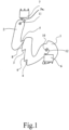
- the proposed motor vehicle lock is equipped with an in 1 equipped with a locking mechanism shown only as an example, which has a rotating bolt 1 and a pawl 2.
- the rotary latch 1 and the pawl 2 are designed here in the usual way as metal stampings. But there are many other variants for the realization of the rotating bolt 1 and the pawl 2 conceivable.
- the pawl 2 can also be designed as a bendable pawl wire that can be brought into locking engagement with the rotating bolt 1 .
- Turnbuckle 1 is in the in 1 shown open position, can be brought into a pre-locked position and in a main locked position.
- the rotating bolt 1 has a corresponding first catch 3 and a main catch 4 .
- the pawl 2 is in a drop-in position, in which it holds the rotating bolt 1 in the main locking position in the pre-locking position, and in the in 1 shown lifting position, in which it releases the rotating bolt 1, can be brought.
- the pawl 2 is equipped with a hook-like formation 5 which can be brought into holding engagement with the first catch 3 and the main catch 4 .
- the locking mechanism is assigned a circuit arrangement for detecting locking states, from which 1 only one rotary bolt switch 6 for detecting the rotary bolt position and one ratchet switch 7 for detecting the ratchet position are shown.
- the two above switches 6, 7 are at in 1 illustrated, preferred variant each configured as a microswitch, which further preferably have a linearly movable plunger as a switching element.
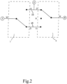
- a schematic circuit diagram of the above circuit arrangement is in 2 shown.
- the circuit diagram shows the fact that the rotating bolt switch 6 can be brought into three switching states, while the pawl switch 7 can be brought into two switching states.
- the three or two switching states are assumed depending on the turning bolt position or the pawl position.
- the proposed solution can be applied particularly advantageously to an arrangement in which the pawl 2 interacts with the rotary bolt 1 as follows:
- the rotary bolt 1 in the open position holds the pawl 2 according to FIG 1 in the withdrawal order.
- the pawl 2 is regularly in contact with a back piece 8 of the rotating bolt 1, as is the case here.
- An adjustment of the rotating bolt 1 from the open position to the pre-locking position causes the pawl 2 to drop into the drop-in position.
- the hook-like formation 5 of the pawl 2 comes into engagement with the first catch 3 of the rotary bolt 1.
- An adjustment of the rotary bolt 1 from the first catch position in the direction of the main catch position again causes the pawl 2 to be lifted into the lifted position.
- the pawl 2 slides along a second back piece 9 of the rotating bolt 1 .
- a further adjustment of the rotating bolt 1 into the main locking position now causes the repeated engagement of the pawl 2 in the engaged position.
- the hook-like formation 5 of the pawl 2 comes into holding engagement with the main catch 4 of the rotating bolt 1.
- the rotary bolt 1 which can be pivoted about a rotary bolt axis 10 , has a contour 12 associated with the rotary bolt switch 6 .
- the contour 12 is in engagement with a movable switching element of the rotary bolt switch 6 and, depending on the position of the rotary bolt 1, ensures that the switching element is deflected accordingly.
- the contour 12 is here and preferably configured in the manner of a web which protrudes from the rotating bolt 1 in the direction of the rotating bolt axis 10 .
- the pawl 2 which is pivotable about a pawl axis 11, is equipped with a contour 7a, which is correspondingly engaged with the pawl switch 7 or can be brought into engagement.
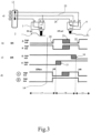
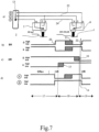
- Figure 3a shows the circuit arrangement for detecting the locking states with the rotary bolt switch 6 and the pawl switch 7, which according to the circuit in 2 is constructed.
- the two switches 6, 7 are connected to a switching strip 13, via which the circuit arrangement can be connected to a higher-level controller.
- the safety edge 13 has an input E to which ground potential is preferably applied.
- the safety edge 13 also has two signal outputs A, B.
- Figure 3a shows the internal switching position within the two switches 6, 7 for the respective closed state.
- the Figure 3b ) and c) each show the switching curves of the pawl switch 7 and the rotary bolt switch 6 over the adjustment range of the rotary bolt 1.
- the switching curves of the pawl switch 7 are labeled "SK”
- the switch curves of the rotary bolt switch 6 are labeled "DR”.
- FIG. 3d shows the resulting signal curve at the signal outputs A and B.
- a vertical pointer 14 extends over the drawings 3b), c) and d) to show which position of the rotating bolt 1 the in Figure 3a ) corresponds to the switching state shown.
- the rotary bolt switch 6 has two switching points 15, 16, which are on the one hand near the pre-locked position VR and on the other hand near the main lock position HR. It is preferably the case that the adjustment range of rotary bolt 1 with regard to the switching positions of rotary bolt switch 6 here and preferably immediately next to one another has an open adjustment range 17, an intermediate adjustment range 18 and a main locking adjustment range 19, in which rotary bolt switch 6 correspondingly an open switch position ( 3 , 4 ), an intermediate switching position ( figure 5 , 6 ) and a main position ( 7 , 8th ) occupies.
- the open position and the pre-locked position in the open adjustment range 17 ( 3 , 4 ) are located and that the main locking position is in the main locking adjustment range 19 ( 7 , 8th ) is located.
- the switching points 15, 16 are arranged at a distance from the pre-locking position VR on the one hand and the main locking position HR on the other hand. This allows a switching behavior that is particularly insensitive to tolerances to be implemented. The geometric tolerances that occur in the motor vehicle lock in question are explained further below.
- the representation in Figure 3b The switching points 20, 21, 22 of the pawl 2 can also be seen.
- the lifted position of the pawl 2 corresponds to a lifted switching position and the engaged position of the pawl 2 corresponds to an engaged switching position of the pawl switch 7.
- the switching point 20 corresponds to the engagement of the pawl 2 in the first position 3, while the switching point 21 corresponds to the repeated lifting of the pawl 2 corresponds to the adjustment of the rotating bolt 1 in the direction of the main detent position.
- the switching point 22 goes back to the engagement of the pawl 2 in the main position 4.
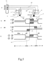
- FIG. 3 A synopsis of Figures 3 to 8 shows that the two switches 6, 7 are interconnected in such a way that the circuit arrangement provides a first binary signal output A and a second binary signal output B, specifically to indicate an open state ( 3 ), in which the rotating bolt 1 is in the open position and the pawl 2 is in the lifted position, a pre-locking state ( 4 ), in which the rotating bolt 1 is in the pre-locked position and the pawl 2 is in the closed position and a main locking state ( 8 ) in which the rotating bolt 1 is in the main locking position and the pawl 2 is in the closed position.
- An intermediate state can also be displayed, which here and preferably includes various constellations ( 6 , 7 ).
- a constellation associated with the intermediate state is that the rotating bolt 1 is in any case in the area of the main locking position, in particular in the main locking position, and the pawl 2 is in the lifted position (apparent locking). this is in 7 shown for the state in which the rotary latch 1 has not yet fully reached the main detent position.
- the intermediate position also includes the constellation in which the Turnbuckle 1 is in the middle area between the pre-locked position and the main locked position and the pawl 2 is in the lifted position ( 6 ).
- a combination of these two states in the intermediate state is appropriate, since both constellations are not the constellations to be primarily recorded.
- the circuit arrangement provides an input E which is connected to an input potential for switching through to the two signal outputs A, B.
- the input potential is the ground potential in the exemplary embodiment that is shown and is preferred in this respect.
- the signal outputs A, B are regularly connected to a pull-up resistor, so that these signal outputs have a high potential if they are not connected to ground potential via the switches 6, 7.
- the above switches are electronic switches in which the switching process is not based on physical contact but essentially on a measuring process.
- the Figures 2 to 8 show, however, an embodiment with electromechanically contacting switches, which are characterized by high robustness and low cost.
- the two switches 6, 7 are designed as changeover switches and each have a central contact M and two switch contacts that can be brought into contact with the central contact M, depending on the switching position.
- the middle contact M is assigned to the movable switching element of the respective changeover switch 6, 7 and is regularly referred to as the "common" contact.
- the rotary bolt switch 6 is designed as a center-zero switch. This means that the rotary bolt switch 6 is not only assigned two switch positions in order to connect the switch contacts ⁇ and S to the center contact M, but also a center-zero switch position, which lies in particular between the two other switch positions and which here and preferably the Intermediate switching position is ( figure 5 , 6 ).
- the center-zero switch position of the rotary latch switch 6 is in the figure 5 , 6 , indicated by the reference character "N".
- the center contact M When the rotary bolt switch 6 is in the center-zero switching position, the center contact M is usually connected neither to the two switching contacts ⁇ , S, nor to any other contact, which, in combination with a pull-up resistor mentioned above, leads to a particularly simple structure . However, it would be conceivable to assign a further contact to the center-zero switching position, which would be in connection with the center contact M in the center-zero switching position and could be connected accordingly.
- the two switching contacts ⁇ , S of the rotary latch switch 6 are each bridged with a different switching contact ⁇ , S of the pawl switch 7, with one of the two bridges 23 providing the first signal output A of the circuit arrangement. This can be shown in the illustration 2 and 3 to 8 remove well.
- the center contact M of the rotary latch switch 6 provides the second signal output B of the circuit arrangement and that the center contact M of the pawl switch 7 provides the input E of the circuit arrangement, to which the input potential is applied.
- center contact M of the pawl switch 7 to provide the second signal output B of the circuit arrangement and for the center contact M of the other switch, in this case the rotary latch switch 6, to provide the input of the circuit arrangement, to which the input potential is applied.
- the transition from 3 on 4 corresponds to the engagement of the pawl 2 in the first position 3, while the rotary bolt switch 6 is in the open switch position.
- the transition from 4 on figure 5 shows the further adjustment of the rotary bolt 1, in which the rotary bolt switch 6 reaches the intermediate switching position without the pawl 2 changing its position.
- the transition from figure 5 on 6 shows the further adjustment of the rotary bolt 1 with the rotary bolt switch 6 remaining in the intermediate switching position, while the pawl 2 is lifted repeatedly.
- the transition from 6 on 7 shows the transfer of the rotary bolt switch 6 from the intermediate switching position to the main locking switching position with an unchanged pawl position.
- the transition from 7 on 8 finally shows the engagement of the pawl 2 in the main position 4 with the rotary bolt switch 6 still in the main position.
- the signal outputs A, B clearly indicate that the open position ( 3 ), the pre-locking position ( 4 ) and the main detent position ( 8 ) show.
- the intermediate state ( 6 , 7 ) is achieved, among other things, when there is an apparent closure, i.e. the turning bolt 1 is in the main locking position and the pawl 2 is in the lifted position. This can easily be shown by starting from the constellation outlined below 8 the pawl 2 from the dropped position is transferred to the withdrawal order. The resulting constellation corresponds exactly to that in 7 shown constellation, i.e. the intermediate state.
- the circuit arrangement according to the proposal is particularly robust against geometric and electrical tolerances, which lead to a shifting of the respective switching points 15, 16, 20, 21, 22.
- the switching points 15, 16, 21 associated geometric tolerances are in the Figures 3 to 8 shown hatched (the geometric tolerances associated with switching points 20 and 22 are negligibly small).
- This representation shows the fact that, in relation to the rotary bolt position, the respective positions of the switching points 15, 16 of the rotary bolt switch 6, here between the open switching position and the intermediate switching position and between the intermediate switching position and the main locking switching position, have geometric tolerances are subject to corresponding tolerance ranges. What is striking here is the fact that within these tolerance ranges, a change in the switching position of the rotary latch switch 6 has no effect on the signal outputs A, B of the circuit arrangement.
- the circuit arrangement is correspondingly robust against such tolerances.
- the pawl switch 7 associated geometric tolerances. It is the case that the respective positions of the switching points 20, 21, 22 of the pawl switch 7, here only the position of the switching point 21 to a significant extent, are or is subject to geometric tolerances with corresponding tolerance ranges in relation to the rotary bolt position. It is now essential that the tolerance range associated with the locking pawl 2 is at a distance from the tolerance ranges associated with the rotary bolt switch 6 in relation to the position of the rotary bolt. If these tolerance ranges overlapped, an unambiguous determination of the closed state in certain constellations would not be possible with certainty. This boundary condition, which affects the extension of the tolerance ranges, can easily be implemented by a suitable mechanical design of the overall arrangement.
- the advantages of the proposed circuit arrangement for a motor vehicle lock is particularly evident when the motor vehicle lock is assigned a non-illustrated closing aid device for motorized execution of a closing process.
- the door, flap or the like assigned to the motor vehicle lock is moved from a pre-closed position to a main closed position against the counteracting force of seals, springs, friction or the like.
- the closing process is the last section of the closing process of the door, hatch or the like. In such arrangements, the closing process usually begins with a gap between the door, hatch or the like and the motor vehicle body of about 6 mm.
- the closing aid can be based on different functional principles.
- the closing aid device makes it possible, as part of the closing aid process, to transfer the rotating bolt 1 by motor from the pre-locked position to the main locked position, which is accompanied by the motorized transfer of the door, flap or the like from the above pre-locked position to the main locked position.
- a second constructive variant for the design of the closing aid consists in that a locking wedge, which normally is arranged on the motor vehicle body and which comes into engagement with the rotating bolt 1 during the locking process, can be adjusted by a motor between a pre-locking position and a main locking position. Then the arrangement is preferably made such that a corresponding adjustment of the locking wedge or the like when the rotary bolt 1 is in the main locking position is accompanied by an adjustment of the flap, door or the like from the pre-closed position to the main closed position.
- the two above constructive variants for the design of the closing aid are in the DE 20 2008 007 719 and the DE 10 2004 016 867 A1 U1 explained, which go back to the applicant and the contents of which are made the subject of the present application.
- the trigger event for starting the closing process is usually when rotary bolt 1 reaches the pre-locked position. This means that the user only has to manually close the door, flap or the like until rotary bolt 1 reaches the pre-locked position has reached. The closing auxiliary device then takes over the further closing.
- reaching the main latching position by the rotating bolt 1 represents the trigger event for starting the closing process.
- the locking wedge or the like is in its pre-locked position, so that the user does not have to counteract seal pressures or the like during the manual part of the locking operation .
- the closing process is stopped when the rotary latch 1 has reached its main detent position.
- the trigger event for stopping the closing process is therefore preferably when the rotary latch 1 reaches the main latching position.
- the closing process is preferably triggered by the expiry of a predetermined closing time or by the Tripping of a limit switch stopped.
- monitoring of the expiry of a predetermined closing time can advantageously be provided in both cases in order to intercept endless actuation of the closing auxiliary device in the event of a fault.
- the closing aid device can be an integral part of the motor vehicle lock as a whole. But it is also conceivable that the closing aid device is a part of the motor vehicle lock, which is realized separately from the motor vehicle lock.
- the closing aid is assigned a closing control, which can be part of the higher-level control mentioned above or which can be designed as a separate closing control.
- the closing control is an electronic circuit with few components, which is preferably spatially assigned to the closing auxiliary device.
- the closing control monitors the signal or the signals of at least one signal output B of the two signal outputs A, B and triggers a corresponding closing process depending on the signal or the signals at the at least one monitored signal output A, B.
- the closing control monitors exactly one signal output of the two signal outputs A, B, here and preferably signal output B, and, as indicated above, triggers a corresponding closing process depending on the signal from the one monitored signal output A, B.
- the closing assist control monitors the signal at the monitored signal output B, namely the signal at the center contact M of the rotary latch switch 6, for the occurrence of a positive signal edge here, with a corresponding closing process being triggered when the positive signal edge occurs becomes.
- the existence of the first structural variant for the closing aid device is assumed here. The same can of course be implemented advantageously for the occurrence of a negative signal edge if the closing aid device is implemented according to the second structural variant.
- the monitoring of the signal at signal output B for the occurrence of a positive edge is sufficient to ensure reliable starting of a closing process.
- the occurrence of this positive signal edge normally means nothing other than that the rotary latch 1 has been transferred from the open position to the pre-locked position. As explained above, this usually forms the trigger event for the closing process. More preferably, it is the case that the closing assist control ends the closing process when a correspondingly negative signal edge occurs. This in turn means that the rotary latch 1 has reached the main latching position, which, as also explained above, usually represents the trigger event for ending the closing process.
- the above actuation of the closing auxiliary device based solely on the signal output B is not only easy to implement in terms of control technology, but also ensures a high level of operational safety even in emergency operation, for example after a failure of the on-board voltage.
- the failure of the on-board voltage represents a potential source of error for the closing control, in particular because switching on the on-board voltage again regularly generates signal edges which, with the system proposed above, lead to the start of a closing process, even if the rotating bolt 1 and/or the pawl 2 is not in one of them intended position.
- the closing process to be started when the rotary latch 1 is in an intermediate position between the pre-locked position and the main locked position or in the main locked position.
- these positions are in the range of movement of the closing aid provided for the rotary latch 1 in any case, so that no mechanical problems are to be expected if the design is suitable.
Landscapes
- Lock And Its Accessories (AREA)
Claims (15)
- Serrure de véhicule automobile, comprenant un mécanisme de fermeture doté d'un loquet rotatif (1) et d'un cliquet d'arrêt (2), le loquet rotatif (1) pouvant être amené dans une position ouverte, dans une position pré-encliquetée et dans une position encliquetée principale, le cliquet d'arrêt (2) pouvant être amené dans une position enclenchée, dans laquelle il retient le loquet rotatif (1) dans la position encliquetée principale et dans la position pré-encliquetée, et dans une position relevée, dans laquelle il libère le loquet rotatif (1), un arrangement de commutation destiné à détecter les états de fermeture étant présent, comprenant un commutateur de loquet rotatif (6) destiné à détecter la position du loquet rotatif et un commutateur de cliquet d'arrêt (7) destiné à détecter la position du cliquet d'arrêt,
caractérisée en ceque le commutateur de loquet rotatif (6) peut être amené dans trois positions de commutation en fonction de la position du loquet rotatif, en ce que le commutateur de cliquet d'arrêt (7) peut être amené dans deux positions de commutation en fonction de la position du cliquet d'arrêt,en ce que les deux commutateurs (6, 7) sont connectés de telle sorte que l'arrangement de commutation fournit une première sortie de signal binaire (A) et une deuxième sortie de signal binaire (B) en vue d'indiquer un état ouvert, dans lequel le loquet rotatif (1) se trouve dans la position ouverte et le cliquet d'arrêt (2) dans la position relevée, un état de pré-encliquetage, dans lequel le loquet rotatif (1) se trouve dans la position pré-encliquetée et le cliquet d'arrêt (2) dans la position enclenchée, un état d'encliquetage principal, dans lequel le loquet rotatif (1) se trouve dans la position encliquetée principale et le cliquet d'arrêt (2) dans la position enclenchée, et un état intermédiaire, dans lequel au moins le loquet rotatif (1) se trouve dans la position encliquetée principale et le cliquet d'arrêt (2) dans la position relevée. - Serrure de véhicule automobile selon la revendication 1, caractérisée en ce que le cliquet d'arrêt (2) coopère avec le loquet rotatif (1) de telle sorte que le loquet rotatif (1) qui se trouve dans la position ouverte maintient le cliquet d'arrêt (2) dans la position relevée, en ce qu'un déplacement du loquet rotatif (1) de la position ouverte dans la position pré-encliquetée provoque l'enclenchement du cliquet d'arrêt (1) dans la position enclenchée, en ce qu'un déplacement du loquet rotatif (1) de la position pré-encliquetée en direction de la position encliquetée principale provoque de nouveau le relevage du cliquet d'arrêt (2) dans la position relevée et en ce qu'une poursuite du déplacement du loquet rotatif (1) dans la position encliquetée principale provoque l'enclenchement du cliquet d'arrêt (2) dans la position enclenchée.
- Serrure de véhicule automobile selon la revendication 1 ou 2, caractérisée en ce que la plage de positionnement du loquet rotatif (1), du point de vue des positions de commutation du commutateur de loquet rotatif (6), présente une plage de positionnement d'ouverture (17), une plage de positionnement intermédiaire (18) et une plage de positionnement principale (19), notamment directement les unes à côté des autres, dans lesquelles le commutateur de loquet rotatif (6) adopte en conséquence une position de commutation d'ouverture, une position de commutation intermédiaire et une position de commutation d'encliquetage principal, encore de préférence en ce que la position ouverte et la position pré-encliquetée sont situées dans la plage de positionnement d'ouverture (17) et en ce que la position encliquetée principale se situe dans la plage de positionnement d'encliquetage principal (19).
- Serrure de véhicule automobile selon l'une des revendications précédentes, caractérisée en ce que la position relevée du cliquet d'arrêt (2) est associée à une position de commutation de relevage et la position enclenchée du cliquet d'arrêt (2) est associée à une position de commutation d'enclenchement du commutateur de cliquet d'arrêt (7).
- Serrure de véhicule automobile selon l'une des revendications précédentes, caractérisée en ce que l'état intermédiaire comprend également la configuration dans laquelle le loquet rotatif (1) se trouve entre la position pré-encliquetée et la position encliquetée principale et le cliquet d'arrêt (22) dans la position relevée.
- Serrure de véhicule automobile selon l'une des revendications précédentes, caractérisée en ce que l'arrangement de commutation fournit une entrée (E) qui est alimentée avec un potentiel d'entrée destiné à être connecté directement aux deux sorties de signal (A, B).
- Serrure de véhicule automobile selon l'une des revendications précédentes, caractérisée en ce que le commutateur de loquet rotatif (6) et le commutateur de cliquet d'arrêt (7) sont respectivement réalisés sous la forme d'un inverseur et possèdent respectivement un contact central (M) et deux contacts de commutation (Ö, S) qui peuvent être amenés en contact avec le contact central (M) en fonction de la position de commutation.
- Serrure de véhicule automobile revendication 7, caractérisée en ce que le commutateur de loquet rotatif (6) est réalisé sous la forme d'un commutateur à position centrale neutre, encore de préférence en ce que la position de commutation centrale neutre (N) du commutateur de loquet rotatif (6) est la position de commutation intermédiaire.
- Serrure de véhicule automobile selon la revendication 7 ou 8, caractérisée en ce que les deux contacts de commutation (Ö, S) du commutateur de loquet rotatif (6) sont respectivement pontés avec un contact de commutation (0, S) différent du commutateur de cliquet d'arrêt (7) et en ce que l'un des deux ponts fournit la première sortie de signal (A) de l'arrangement de commutation.
- Serrure de véhicule automobile selon l'une des revendications 7 à 9, caractérisée en ce que le contact central (M) du commutateur de loquet rotatif (6) ou du commutateur de cliquet d'arrêt (7) fournit la deuxième sortie de signal (B) de l'arrangement de commutation et en ce que le contact central (M) de l'autre commutateur respectif fournit l'entrée (E) de l'arrangement de commutation, laquelle est notamment alimentée avec le potentiel d'entrée.
- Serrure de véhicule automobile selon l'une des revendications précédentes, caractérisée en ce qu'en référence à la position du loquet rotatif, les positions respectives des points de commutation (15, 16) du commutateur de loquet rotatif (6), notamment entre la position de commutation d'ouverture et la position de commutation intermédiaire ainsi qu'entre la position de commutation intermédiaire et la position de commutation d'encliquetage principal, sont soumises à des tolérances géométriques avec des plages de tolérance correspondantes, de préférence en ce qu'à l'intérieur de ces plages de tolérance une modification de la position de commutation du commutateur de loquet rotatif (6) n'a aucun effet sur les sorties de signal (A, B) de l'arrangement de commutation.
- Serrure de véhicule automobile selon l'une des revendications précédentes, caractérisée en ce qu'en référence à la position du loquet rotatif, les positions respectives des points de commutation (20, 21, 22) du commutateur de cliquet d'arrêt (7), notamment la position du point de commutation (21) dans la plage de positionnement intermédiaire, sont soumises à des tolérances géométriques avec des plages de tolérance correspondantes, de préférence en ce qu'en référence à la position du loquet rotatif, les plages de tolérance associées au cliquet d'arrêt (2) sont espacées des plages de tolérance associées au commutateur de loquet rotatif (6) .
- Serrure de véhicule automobile selon l'une des revendications précédentes, caractérisée en ce qu'un dispositif d'aide à la fermeture par traction destiné à accomplir de manière motorisée une opération de fermeture par traction est présent, en ce qu'une commande de fermeture par traction est associée au dispositif d'aide à la fermeture par traction, laquelle surveille le signal ou les signaux d'au moins une sortie de signal (B) des deux sorties de signal (A, B) et déclenche une opération de fermeture par traction en fonction du signal ou des signaux au niveau de l'au moins une sortie de signal (B) surveillée.
- Serrure de véhicule automobile selon la revendication 13, caractérisée en ce que la commande de fermeture par traction surveille une sortie de signal (B) des deux sorties de signal (A, B), notamment le contact central (M) du commutateur de loquet rotatif (6) et déclenche une opération de fermeture par traction en fonction du signal de ladite sortie de signal (A, B) surveillée.
- Serrure de véhicule automobile selon la revendication 13 ou 14, caractérisée en ce que la commande de fermeture par traction surveille le signal au niveau de la sortie de signal (B) surveillée en vue de détecter la survenance d'un front de signal positif ou négatif et démarre une opération de fermeture par traction en cas de survenance d'un front de signal positif ou négatif, de préférence en ce que la commande de fermeture par traction met fin à l'opération de fermeture par traction en cas de survenance d'un front de signal négatif ou positif.
Applications Claiming Priority (1)
| Application Number | Priority Date | Filing Date | Title |
|---|---|---|---|
| DE202009016636U DE202009016636U1 (de) | 2009-12-09 | 2009-12-09 | Kraftfahrzeugschloss |
Publications (4)
| Publication Number | Publication Date |
|---|---|
| EP2333208A2 EP2333208A2 (fr) | 2011-06-15 |
| EP2333208A3 EP2333208A3 (fr) | 2015-07-08 |
| EP2333208B1 EP2333208B1 (fr) | 2020-04-01 |
| EP2333208B2 true EP2333208B2 (fr) | 2023-08-16 |
Family
ID=43838230
Family Applications (1)
| Application Number | Title | Priority Date | Filing Date |
|---|---|---|---|
| EP10015469.9A Active EP2333208B2 (fr) | 2009-12-09 | 2010-12-09 | Serrure de véhicule automobile |
Country Status (2)
| Country | Link |
|---|---|
| EP (1) | EP2333208B2 (fr) |
| DE (1) | DE202009016636U1 (fr) |
Families Citing this family (14)
| Publication number | Priority date | Publication date | Assignee | Title |
|---|---|---|---|---|
| FR2991728B1 (fr) | 2012-06-08 | 2016-04-29 | Bosch Gmbh Robert | Soupape electromagnetique de systeme d'injection de carburant |
| DE102012013779A1 (de) * | 2012-07-11 | 2014-04-24 | Volkswagen Aktiengesellschaft | Verfahren zum Schließen oder Öffnen einer Tür, Heckklappe oder dergleichen an der Karosserie eines Kraftfahrzeugs |
| DE102013106398A1 (de) * | 2013-06-19 | 2014-12-24 | Brose Fahrzeugteile Gmbh & Co. Kommanditgesellschaft, Hallstadt | Erfassungseinrichtung für die Erfassung von mechanischen Funktionszuständen eines Kraftfahrzeugschlosses |
| FR3014472B1 (fr) * | 2013-12-10 | 2017-10-06 | Inteva Products Llc | Ensemble et systeme de verrouillage de portiere |
| WO2017044599A1 (fr) * | 2015-09-08 | 2017-03-16 | Janus International Group, Llc | Appareil de verrouillage électronique pour une porte à enroulement |
| KR101836620B1 (ko) | 2016-04-21 | 2018-03-08 | 현대자동차주식회사 | 차량용 씬칭래치 조립체 |
| US11007972B2 (en) | 2017-09-22 | 2021-05-18 | GM Global Technology Operations LLC | Multi-pull latch and lock systems for compartment closure assemblies of motor vehicles |
| US10704304B2 (en) | 2017-10-26 | 2020-07-07 | GM Global Technology Operations LLC | Memory levers for latch mechanisms of vehicle compartment closure assemblies |
| DE102019102302A1 (de) * | 2019-01-30 | 2020-07-30 | Brose Schließsysteme GmbH & Co. Kommanditgesellschaft | Kraftfahrzeugschlossanordnung |
| DE102019128462A1 (de) * | 2019-10-22 | 2021-04-22 | Kiekert Aktiengesellschaft | Kraftfahrzeugschloss |
| DE102021102766A1 (de) | 2021-02-05 | 2022-08-11 | Brose Schließsysteme GmbH & Co. Kommanditgesellschaft | Kraftfahrzeugschlossanordnung für eine Klappe eines Kraftfahrzeugs |
| DE102022122294A1 (de) | 2022-09-02 | 2024-03-07 | Kiekert Aktiengesellschaft | Kraftfahrzeug-Schloss, insbesondere Kraftfahrzeug-Türschloss |
| DE102023106534A1 (de) * | 2023-03-15 | 2024-09-19 | Brose Schließsysteme GmbH & Co. Kommanditgesellschaft | Kraftfahrzeugschloss mit erstem und zweitem Sperrelement |
| DE102024116623A1 (de) * | 2024-06-13 | 2025-12-18 | Audi Aktiengesellschaft | Schließsystem mit ratschenartiger Funktion |
Citations (13)
| Publication number | Priority date | Publication date | Assignee | Title |
|---|---|---|---|---|
| DE19547724A1 (de) † | 1995-12-20 | 1997-06-26 | Vdo Schindling | Schloß, insbesondere für Kraftfahrzeugtüren |
| DE19702698A1 (de) † | 1996-04-02 | 1997-10-09 | Kiekert Ag | Kraftfahrzeug mit zumindest einer in einer Seitenwand angeordneten Schiebetür |
| DE19632915A1 (de) † | 1996-05-21 | 1997-11-27 | Bosch Gmbh Robert | Verfahren zur Ansteuerung eines elektrisch betätigten Kraftfahrzeug-Türschlosses o. dgl. |
| WO1999049159A1 (fr) † | 1998-03-23 | 1999-09-30 | Huf Hülsbeck & Fürst Gmbh & Co. Kg | Serrure de porte dotee d'un loquet rotatif et destinee notamment a des vehicules |
| DE10261505A1 (de) † | 2002-12-23 | 2004-07-01 | Volkswagen Ag | Verriegelungsvorrichtung für eine Fahrzeugtür |
| DE102004042966A1 (de) † | 2004-09-02 | 2006-03-09 | Brose Schließsysteme GmbH & Co.KG | Kraftfahrzeugschloß |
| EP1637675A1 (fr) † | 2004-09-17 | 2006-03-22 | Gebr. Bode GmbH & Co. KG | Dispositif de verrouillage avec pênes pivotants pour portes sur véhicules de transport en commun, notamment pour véhicules ferroviaires |
| DE102006048026A1 (de) † | 2005-11-08 | 2007-05-10 | BROSE SCHLIEßSYSTEME GMBH & CO. KG | Kraftfahrzeugschloßanordnung |
| DE202006009262U1 (de) † | 2006-06-13 | 2007-10-18 | BROSE SCHLIEßSYSTEME GMBH & CO. KG | Kraftfahrzeugschloß |
| DE102007040714A1 (de) † | 2006-08-31 | 2008-03-06 | Marquardt Gmbh | Elektrischer Schalter |
| EP2006476A2 (fr) † | 2007-06-18 | 2008-12-24 | Brose Schliesssysteme GmbH & Co. KG | Serrure de véhicule automobile |
| EP2071106A1 (fr) † | 2007-12-14 | 2009-06-17 | Ford Global Technologies, LLC | Dispositif de fixation à fermeture motorisée |
| DE102009003402A1 (de) † | 2009-01-29 | 2010-08-05 | Witte-Velbert Gmbh & Co. Kg | Drehfallenverschluss mit Zuziehhilfe |
Family Cites Families (11)
| Publication number | Priority date | Publication date | Assignee | Title |
|---|---|---|---|---|
| DE29714953U1 (de) * | 1997-08-21 | 1997-11-13 | Kiekert AG, 42579 Heiligenhaus | Kraftfahrzeugtürverschluß mit Kraftfahrzeugtürschloß, Servo-Schloßhalter und elektrischer Steuereinrichtung |
| DE19861199B4 (de) * | 1997-10-06 | 2007-04-26 | Mitsui Kinzoku Kogyo K.K. | Verriegelungsvorrichtung für eine Fahrzeugtür |
| FR2778939B1 (fr) | 1998-05-20 | 2002-12-06 | Valeo Securite Habitacle | Indicateur d'etat de fermeture pour serrure de portiere de vehicule automobile et serrure incorporant un tel indicateur |
| FR2837232B1 (fr) * | 2002-03-15 | 2004-10-01 | Meritor Light Vehicle Sys Ltd | Serrure de vehicule automobile |
| DE102004016867A1 (de) | 2004-04-03 | 2005-10-20 | Brose Schliesssysteme Gmbh | Schließkeil-Antriebsbaugruppe für ein Kraftfahrzeugschloß |
| FR2873144B1 (fr) * | 2004-07-13 | 2013-03-22 | Arvinmeritor Light Vehicle Sys | Serrure de vehicule automobile |
| DE102004054739B4 (de) * | 2004-11-12 | 2022-12-15 | Bayerische Motoren Werke Aktiengesellschaft | Schloss mit motorischer Schliesshilfe |
| GB0522793D0 (en) * | 2005-11-09 | 2005-12-14 | Arvinmeritor Light Vehicle Sys | Door latch |
| DE102006057679B4 (de) * | 2006-12-07 | 2011-11-03 | Audi Ag | Vorrichtung und Verfahren zum Verschließen eines angetriebenen Bauteils |
| DE102007056251A1 (de) * | 2007-07-24 | 2009-01-29 | Kiekert Ag | Kraftfahrzeugverschlussanordnung und Verfahren zu dessen Betrieb |
| DE202008007719U1 (de) | 2007-12-03 | 2009-04-16 | BROSE SCHLIEßSYSTEME GMBH & CO. KG | Schließhilfsantrieb für ein Kraftfahrzeugschloß |
-
2009
- 2009-12-09 DE DE202009016636U patent/DE202009016636U1/de not_active Expired - Lifetime
-
2010
- 2010-12-09 EP EP10015469.9A patent/EP2333208B2/fr active Active
Patent Citations (13)
| Publication number | Priority date | Publication date | Assignee | Title |
|---|---|---|---|---|
| DE19547724A1 (de) † | 1995-12-20 | 1997-06-26 | Vdo Schindling | Schloß, insbesondere für Kraftfahrzeugtüren |
| DE19702698A1 (de) † | 1996-04-02 | 1997-10-09 | Kiekert Ag | Kraftfahrzeug mit zumindest einer in einer Seitenwand angeordneten Schiebetür |
| DE19632915A1 (de) † | 1996-05-21 | 1997-11-27 | Bosch Gmbh Robert | Verfahren zur Ansteuerung eines elektrisch betätigten Kraftfahrzeug-Türschlosses o. dgl. |
| WO1999049159A1 (fr) † | 1998-03-23 | 1999-09-30 | Huf Hülsbeck & Fürst Gmbh & Co. Kg | Serrure de porte dotee d'un loquet rotatif et destinee notamment a des vehicules |
| DE10261505A1 (de) † | 2002-12-23 | 2004-07-01 | Volkswagen Ag | Verriegelungsvorrichtung für eine Fahrzeugtür |
| DE102004042966A1 (de) † | 2004-09-02 | 2006-03-09 | Brose Schließsysteme GmbH & Co.KG | Kraftfahrzeugschloß |
| EP1637675A1 (fr) † | 2004-09-17 | 2006-03-22 | Gebr. Bode GmbH & Co. KG | Dispositif de verrouillage avec pênes pivotants pour portes sur véhicules de transport en commun, notamment pour véhicules ferroviaires |
| DE102006048026A1 (de) † | 2005-11-08 | 2007-05-10 | BROSE SCHLIEßSYSTEME GMBH & CO. KG | Kraftfahrzeugschloßanordnung |
| DE202006009262U1 (de) † | 2006-06-13 | 2007-10-18 | BROSE SCHLIEßSYSTEME GMBH & CO. KG | Kraftfahrzeugschloß |
| DE102007040714A1 (de) † | 2006-08-31 | 2008-03-06 | Marquardt Gmbh | Elektrischer Schalter |
| EP2006476A2 (fr) † | 2007-06-18 | 2008-12-24 | Brose Schliesssysteme GmbH & Co. KG | Serrure de véhicule automobile |
| EP2071106A1 (fr) † | 2007-12-14 | 2009-06-17 | Ford Global Technologies, LLC | Dispositif de fixation à fermeture motorisée |
| DE102009003402A1 (de) † | 2009-01-29 | 2010-08-05 | Witte-Velbert Gmbh & Co. Kg | Drehfallenverschluss mit Zuziehhilfe |
Also Published As
| Publication number | Publication date |
|---|---|
| EP2333208B1 (fr) | 2020-04-01 |
| EP2333208A2 (fr) | 2011-06-15 |
| EP2333208A3 (fr) | 2015-07-08 |
| DE202009016636U1 (de) | 2011-04-21 |
Similar Documents
| Publication | Publication Date | Title |
|---|---|---|
| EP2333208B2 (fr) | Serrure de véhicule automobile | |
| DE68917421T2 (de) | Verriegelung für Kraftfahrzeugtür. | |
| EP1544388B1 (fr) | Véhicule automobile | |
| EP3011121B1 (fr) | Système de détection d'états fonctionnels mécaniques d'une serrure de véhicule automobile | |
| EP0826855A2 (fr) | Serrure, spécialement pour portes de véhicules ou similaires | |
| DE102016210251A1 (de) | Schließzylinder-Freigabemechanismus für Fahrzeugschließverriegelungen, Verriegelungsanordnung damit und Verfahren zum mechanischen Freigeben einer Fahrzeugschließverriegelung | |
| EP2831356A2 (fr) | Serrure de porte de véhicule automobile | |
| WO2014059966A2 (fr) | Serrure de portière de véhicule automobile | |
| DE19717638C2 (de) | Türschließvorrichtung | |
| EP1457625A2 (fr) | Serrure pour véhicule à ouverture assistée électriquement | |
| EP2313584A1 (fr) | Fermeture de portiere de vehicule a moteur avec une circuiterie | |
| WO2022167556A2 (fr) | Système de serrure de véhicule à moteur pour un ouvrant de véhicule à moteur | |
| EP2006476A2 (fr) | Serrure de véhicule automobile | |
| DE102006048026A1 (de) | Kraftfahrzeugschloßanordnung | |
| EP1658410A1 (fr) | Serrure de portiere de vehicule automobile | |
| WO2016206665A1 (fr) | Serrure de portière de véhicule à moteur | |
| EP1391573A2 (fr) | Serrure pour véhicule | |
| WO2021148082A1 (fr) | Dispositif d'actionnement destiné à une serrure de véhicule automobile | |
| EP1317696A1 (fr) | Dispositif d'activation d'un appareil de commande | |
| WO2007065418A1 (fr) | Dispositif de verrouillage pour une construction de toit de cabriolet | |
| DE10319743A1 (de) | Kraftfahrzeugschloß mit elektrischem Öffnungsantrieb | |
| DE4127638C2 (de) | Steuerschaltung für Verstellmotoren, insbesondere für Fensterhebermotoren | |
| EP3798393A1 (fr) | Dispositif de commande d'urgence destiné à l'ouverture manuelle d'une porte de véhicule | |
| EP1447830B1 (fr) | Dispositif de commutation pour le codage de différents états | |
| DE102015205343A1 (de) | Elektrische Betätigungseinrichtung mit Notbestromung für ein Kraftfahrzeugelektroschloss und Verfahren |
Legal Events
| Date | Code | Title | Description |
|---|---|---|---|
| PUAI | Public reference made under article 153(3) epc to a published international application that has entered the european phase |
Free format text: ORIGINAL CODE: 0009012 |
|
| AK | Designated contracting states |
Kind code of ref document: A2 Designated state(s): AL AT BE BG CH CY CZ DE DK EE ES FI FR GB GR HR HU IE IS IT LI LT LU LV MC MK MT NL NO PL PT RO RS SE SI SK SM TR |
|
| PUAL | Search report despatched |
Free format text: ORIGINAL CODE: 0009013 |
|
| AK | Designated contracting states |
Kind code of ref document: A3 Designated state(s): AL AT BE BG CH CY CZ DE DK EE ES FI FR GB GR HR HU IE IS IT LI LT LU LV MC MK MT NL NO PL PT RO RS SE SI SK SM TR |
|
| RIC1 | Information provided on ipc code assigned before grant |
Ipc: E05B 65/32 00000000AFI20150529BHEP Ipc: E05B 17/22 20060101ALI20150529BHEP |
|
| 17P | Request for examination filed |
Effective date: 20160108 |
|
| RBV | Designated contracting states (corrected) |
Designated state(s): AL AT BE BG CH CY CZ DE DK EE ES FI FR GB GR HR HU IE IS IT LI LT LU LV MC MK MT NL NO PL PT RO RS SE SI SK SM TR |
|
| STAA | Information on the status of an ep patent application or granted ep patent |
Free format text: STATUS: EXAMINATION IS IN PROGRESS |
|
| 17Q | First examination report despatched |
Effective date: 20180420 |
|
| REG | Reference to a national code |
Ref country code: DE Ref legal event code: R079 Ref document number: 502010016559 Country of ref document: DE Free format text: PREVIOUS MAIN CLASS: E05B0065320000 Ipc: E05B0081680000 |
|
| RIC1 | Information provided on ipc code assigned before grant |
Ipc: E05B 81/66 20140101ALN20190919BHEP Ipc: E05B 81/68 20140101AFI20190919BHEP Ipc: E05B 85/26 20140101ALI20190919BHEP Ipc: E05B 81/20 20140101ALI20190919BHEP |
|
| RIC1 | Information provided on ipc code assigned before grant |
Ipc: E05B 85/26 20140101ALI20190926BHEP Ipc: E05B 81/20 20140101ALI20190926BHEP Ipc: E05B 81/66 20140101ALN20190926BHEP Ipc: E05B 81/68 20140101AFI20190926BHEP |
|
| GRAP | Despatch of communication of intention to grant a patent |
Free format text: ORIGINAL CODE: EPIDOSNIGR1 |
|
| STAA | Information on the status of an ep patent application or granted ep patent |
Free format text: STATUS: GRANT OF PATENT IS INTENDED |
|
| RIC1 | Information provided on ipc code assigned before grant |
Ipc: E05B 85/26 20140101ALI20190927BHEP Ipc: E05B 81/68 20140101AFI20190927BHEP Ipc: E05B 81/20 20140101ALI20190927BHEP Ipc: E05B 81/66 20140101ALN20190927BHEP |
|
| INTG | Intention to grant announced |
Effective date: 20191106 |
|
| GRAS | Grant fee paid |
Free format text: ORIGINAL CODE: EPIDOSNIGR3 |
|
| GRAA | (expected) grant |
Free format text: ORIGINAL CODE: 0009210 |
|
| STAA | Information on the status of an ep patent application or granted ep patent |
Free format text: STATUS: THE PATENT HAS BEEN GRANTED |
|
| AK | Designated contracting states |
Kind code of ref document: B1 Designated state(s): AL AT BE BG CH CY CZ DE DK EE ES FI FR GB GR HR HU IE IS IT LI LT LU LV MC MK MT NL NO PL PT RO RS SE SI SK SM TR |
|
| REG | Reference to a national code |
Ref country code: GB Ref legal event code: FG4D Free format text: NOT ENGLISH |
|
| REG | Reference to a national code |
Ref country code: AT Ref legal event code: REF Ref document number: 1251521 Country of ref document: AT Kind code of ref document: T Effective date: 20200415 Ref country code: CH Ref legal event code: EP |
|
| REG | Reference to a national code |
Ref country code: DE Ref legal event code: R096 Ref document number: 502010016559 Country of ref document: DE |
|
| REG | Reference to a national code |
Ref country code: IE Ref legal event code: FG4D Free format text: LANGUAGE OF EP DOCUMENT: GERMAN |
|
| PG25 | Lapsed in a contracting state [announced via postgrant information from national office to epo] |
Ref country code: BG Free format text: LAPSE BECAUSE OF FAILURE TO SUBMIT A TRANSLATION OF THE DESCRIPTION OR TO PAY THE FEE WITHIN THE PRESCRIBED TIME-LIMIT Effective date: 20200701 |
|
| REG | Reference to a national code |
Ref country code: NL Ref legal event code: MP Effective date: 20200401 |
|
| REG | Reference to a national code |
Ref country code: LT Ref legal event code: MG4D |
|
| PG25 | Lapsed in a contracting state [announced via postgrant information from national office to epo] |
Ref country code: NL Free format text: LAPSE BECAUSE OF FAILURE TO SUBMIT A TRANSLATION OF THE DESCRIPTION OR TO PAY THE FEE WITHIN THE PRESCRIBED TIME-LIMIT Effective date: 20200401 Ref country code: IS Free format text: LAPSE BECAUSE OF FAILURE TO SUBMIT A TRANSLATION OF THE DESCRIPTION OR TO PAY THE FEE WITHIN THE PRESCRIBED TIME-LIMIT Effective date: 20200801 Ref country code: GR Free format text: LAPSE BECAUSE OF FAILURE TO SUBMIT A TRANSLATION OF THE DESCRIPTION OR TO PAY THE FEE WITHIN THE PRESCRIBED TIME-LIMIT Effective date: 20200702 Ref country code: NO Free format text: LAPSE BECAUSE OF FAILURE TO SUBMIT A TRANSLATION OF THE DESCRIPTION OR TO PAY THE FEE WITHIN THE PRESCRIBED TIME-LIMIT Effective date: 20200701 Ref country code: SE Free format text: LAPSE BECAUSE OF FAILURE TO SUBMIT A TRANSLATION OF THE DESCRIPTION OR TO PAY THE FEE WITHIN THE PRESCRIBED TIME-LIMIT Effective date: 20200401 Ref country code: FI Free format text: LAPSE BECAUSE OF FAILURE TO SUBMIT A TRANSLATION OF THE DESCRIPTION OR TO PAY THE FEE WITHIN THE PRESCRIBED TIME-LIMIT Effective date: 20200401 Ref country code: PT Free format text: LAPSE BECAUSE OF FAILURE TO SUBMIT A TRANSLATION OF THE DESCRIPTION OR TO PAY THE FEE WITHIN THE PRESCRIBED TIME-LIMIT Effective date: 20200817 Ref country code: LT Free format text: LAPSE BECAUSE OF FAILURE TO SUBMIT A TRANSLATION OF THE DESCRIPTION OR TO PAY THE FEE WITHIN THE PRESCRIBED TIME-LIMIT Effective date: 20200401 |
|
| PG25 | Lapsed in a contracting state [announced via postgrant information from national office to epo] |
Ref country code: LV Free format text: LAPSE BECAUSE OF FAILURE TO SUBMIT A TRANSLATION OF THE DESCRIPTION OR TO PAY THE FEE WITHIN THE PRESCRIBED TIME-LIMIT Effective date: 20200401 Ref country code: RS Free format text: LAPSE BECAUSE OF FAILURE TO SUBMIT A TRANSLATION OF THE DESCRIPTION OR TO PAY THE FEE WITHIN THE PRESCRIBED TIME-LIMIT Effective date: 20200401 Ref country code: HR Free format text: LAPSE BECAUSE OF FAILURE TO SUBMIT A TRANSLATION OF THE DESCRIPTION OR TO PAY THE FEE WITHIN THE PRESCRIBED TIME-LIMIT Effective date: 20200401 |
|
| REG | Reference to a national code |
Ref country code: DE Ref legal event code: R026 Ref document number: 502010016559 Country of ref document: DE |
|
| PLBI | Opposition filed |
Free format text: ORIGINAL CODE: 0009260 |
|
| PG25 | Lapsed in a contracting state [announced via postgrant information from national office to epo] |
Ref country code: AL Free format text: LAPSE BECAUSE OF FAILURE TO SUBMIT A TRANSLATION OF THE DESCRIPTION OR TO PAY THE FEE WITHIN THE PRESCRIBED TIME-LIMIT Effective date: 20200401 |
|
| PLAX | Notice of opposition and request to file observation + time limit sent |
Free format text: ORIGINAL CODE: EPIDOSNOBS2 |
|
| 26 | Opposition filed |
Opponent name: KIEKERT AKTIENGESELLSCHAFT Effective date: 20201217 |
|
| PG25 | Lapsed in a contracting state [announced via postgrant information from national office to epo] |
Ref country code: RO Free format text: LAPSE BECAUSE OF FAILURE TO SUBMIT A TRANSLATION OF THE DESCRIPTION OR TO PAY THE FEE WITHIN THE PRESCRIBED TIME-LIMIT Effective date: 20200401 Ref country code: ES Free format text: LAPSE BECAUSE OF FAILURE TO SUBMIT A TRANSLATION OF THE DESCRIPTION OR TO PAY THE FEE WITHIN THE PRESCRIBED TIME-LIMIT Effective date: 20200401 Ref country code: DK Free format text: LAPSE BECAUSE OF FAILURE TO SUBMIT A TRANSLATION OF THE DESCRIPTION OR TO PAY THE FEE WITHIN THE PRESCRIBED TIME-LIMIT Effective date: 20200401 Ref country code: SM Free format text: LAPSE BECAUSE OF FAILURE TO SUBMIT A TRANSLATION OF THE DESCRIPTION OR TO PAY THE FEE WITHIN THE PRESCRIBED TIME-LIMIT Effective date: 20200401 Ref country code: EE Free format text: LAPSE BECAUSE OF FAILURE TO SUBMIT A TRANSLATION OF THE DESCRIPTION OR TO PAY THE FEE WITHIN THE PRESCRIBED TIME-LIMIT Effective date: 20200401 Ref country code: IT Free format text: LAPSE BECAUSE OF FAILURE TO SUBMIT A TRANSLATION OF THE DESCRIPTION OR TO PAY THE FEE WITHIN THE PRESCRIBED TIME-LIMIT Effective date: 20200401 |
|
| PGFP | Annual fee paid to national office [announced via postgrant information from national office to epo] |
Ref country code: FR Payment date: 20201112 Year of fee payment: 11 |
|
| PG25 | Lapsed in a contracting state [announced via postgrant information from national office to epo] |
Ref country code: SK Free format text: LAPSE BECAUSE OF FAILURE TO SUBMIT A TRANSLATION OF THE DESCRIPTION OR TO PAY THE FEE WITHIN THE PRESCRIBED TIME-LIMIT Effective date: 20200401 Ref country code: PL Free format text: LAPSE BECAUSE OF FAILURE TO SUBMIT A TRANSLATION OF THE DESCRIPTION OR TO PAY THE FEE WITHIN THE PRESCRIBED TIME-LIMIT Effective date: 20200401 |
|
| PG25 | Lapsed in a contracting state [announced via postgrant information from national office to epo] |
Ref country code: SI Free format text: LAPSE BECAUSE OF FAILURE TO SUBMIT A TRANSLATION OF THE DESCRIPTION OR TO PAY THE FEE WITHIN THE PRESCRIBED TIME-LIMIT Effective date: 20200401 |
|
| PLBB | Reply of patent proprietor to notice(s) of opposition received |
Free format text: ORIGINAL CODE: EPIDOSNOBS3 |
|
| REG | Reference to a national code |
Ref country code: CH Ref legal event code: PL |
|
| GBPC | Gb: european patent ceased through non-payment of renewal fee |
Effective date: 20201209 |
|
| PG25 | Lapsed in a contracting state [announced via postgrant information from national office to epo] |
Ref country code: MC Free format text: LAPSE BECAUSE OF FAILURE TO SUBMIT A TRANSLATION OF THE DESCRIPTION OR TO PAY THE FEE WITHIN THE PRESCRIBED TIME-LIMIT Effective date: 20200401 |
|
| REG | Reference to a national code |
Ref country code: BE Ref legal event code: MM Effective date: 20201231 |
|
| PG25 | Lapsed in a contracting state [announced via postgrant information from national office to epo] |
Ref country code: LU Free format text: LAPSE BECAUSE OF NON-PAYMENT OF DUE FEES Effective date: 20201209 Ref country code: IE Free format text: LAPSE BECAUSE OF NON-PAYMENT OF DUE FEES Effective date: 20201209 |
|
| PG25 | Lapsed in a contracting state [announced via postgrant information from national office to epo] |
Ref country code: LI Free format text: LAPSE BECAUSE OF NON-PAYMENT OF DUE FEES Effective date: 20201231 Ref country code: GB Free format text: LAPSE BECAUSE OF NON-PAYMENT OF DUE FEES Effective date: 20201209 Ref country code: CH Free format text: LAPSE BECAUSE OF NON-PAYMENT OF DUE FEES Effective date: 20201231 |
|
| REG | Reference to a national code |
Ref country code: AT Ref legal event code: MM01 Ref document number: 1251521 Country of ref document: AT Kind code of ref document: T Effective date: 20201209 |
|
| PG25 | Lapsed in a contracting state [announced via postgrant information from national office to epo] |
Ref country code: AT Free format text: LAPSE BECAUSE OF NON-PAYMENT OF DUE FEES Effective date: 20201209 |
|
| PG25 | Lapsed in a contracting state [announced via postgrant information from national office to epo] |
Ref country code: TR Free format text: LAPSE BECAUSE OF FAILURE TO SUBMIT A TRANSLATION OF THE DESCRIPTION OR TO PAY THE FEE WITHIN THE PRESCRIBED TIME-LIMIT Effective date: 20200401 Ref country code: MT Free format text: LAPSE BECAUSE OF FAILURE TO SUBMIT A TRANSLATION OF THE DESCRIPTION OR TO PAY THE FEE WITHIN THE PRESCRIBED TIME-LIMIT Effective date: 20200401 Ref country code: CY Free format text: LAPSE BECAUSE OF FAILURE TO SUBMIT A TRANSLATION OF THE DESCRIPTION OR TO PAY THE FEE WITHIN THE PRESCRIBED TIME-LIMIT Effective date: 20200401 |
|
| PG25 | Lapsed in a contracting state [announced via postgrant information from national office to epo] |
Ref country code: MK Free format text: LAPSE BECAUSE OF FAILURE TO SUBMIT A TRANSLATION OF THE DESCRIPTION OR TO PAY THE FEE WITHIN THE PRESCRIBED TIME-LIMIT Effective date: 20200401 |
|
| PG25 | Lapsed in a contracting state [announced via postgrant information from national office to epo] |
Ref country code: BE Free format text: LAPSE BECAUSE OF NON-PAYMENT OF DUE FEES Effective date: 20201231 |
|
| PG25 | Lapsed in a contracting state [announced via postgrant information from national office to epo] |
Ref country code: FR Free format text: LAPSE BECAUSE OF NON-PAYMENT OF DUE FEES Effective date: 20211231 |
|
| PUAH | Patent maintained in amended form |
Free format text: ORIGINAL CODE: 0009272 |
|
| STAA | Information on the status of an ep patent application or granted ep patent |
Free format text: STATUS: PATENT MAINTAINED AS AMENDED |
|
| 27A | Patent maintained in amended form |
Effective date: 20230816 |
|
| AK | Designated contracting states |
Kind code of ref document: B2 Designated state(s): AL AT BE BG CH CY CZ DE DK EE ES FI FR GB GR HR HU IE IS IT LI LT LU LV MC MK MT NL NO PL PT RO RS SE SI SK SM TR |
|
| REG | Reference to a national code |
Ref country code: DE Ref legal event code: R102 Ref document number: 502010016559 Country of ref document: DE |
|
| PGFP | Annual fee paid to national office [announced via postgrant information from national office to epo] |
Ref country code: CZ Payment date: 20241119 Year of fee payment: 15 |
|
| PG25 | Lapsed in a contracting state [announced via postgrant information from national office to epo] |
Ref country code: IS Free format text: LAPSE BECAUSE OF NON-PAYMENT OF DUE FEES Effective date: 20200801 |
|
| PGFP | Annual fee paid to national office [announced via postgrant information from national office to epo] |
Ref country code: DE Payment date: 20251231 Year of fee payment: 16 |