EP2006476A2 - Serrure de véhicule automobile - Google Patents
Serrure de véhicule automobile Download PDFInfo
- Publication number
- EP2006476A2 EP2006476A2 EP08010424A EP08010424A EP2006476A2 EP 2006476 A2 EP2006476 A2 EP 2006476A2 EP 08010424 A EP08010424 A EP 08010424A EP 08010424 A EP08010424 A EP 08010424A EP 2006476 A2 EP2006476 A2 EP 2006476A2
- Authority
- EP
- European Patent Office
- Prior art keywords
- switching
- motor vehicle
- lock
- adjusting element
- switch element
- Prior art date
- Legal status (The legal status is an assumption and is not a legal conclusion. Google has not performed a legal analysis and makes no representation as to the accuracy of the status listed.)
- Withdrawn
Links
- 238000001514 detection method Methods 0.000 description 9
- 239000000463 material Substances 0.000 description 3
- TVEXGJYMHHTVKP-UHFFFAOYSA-N 6-oxabicyclo[3.2.1]oct-3-en-7-one Chemical compound C1C2C(=O)OC1C=CC2 TVEXGJYMHHTVKP-UHFFFAOYSA-N 0.000 description 1
- RTAQQCXQSZGOHL-UHFFFAOYSA-N Titanium Chemical compound [Ti] RTAQQCXQSZGOHL-UHFFFAOYSA-N 0.000 description 1
- 238000013459 approach Methods 0.000 description 1
- 230000000694 effects Effects 0.000 description 1
- 230000002349 favourable effect Effects 0.000 description 1
- 230000001939 inductive effect Effects 0.000 description 1
- 229910052751 metal Inorganic materials 0.000 description 1
- 239000002184 metal Substances 0.000 description 1
- 239000010936 titanium Substances 0.000 description 1
- 229910052719 titanium Inorganic materials 0.000 description 1
Images


Classifications
-
- H—ELECTRICITY
- H01—ELECTRIC ELEMENTS
- H01H—ELECTRIC SWITCHES; RELAYS; SELECTORS; EMERGENCY PROTECTIVE DEVICES
- H01H3/00—Mechanisms for operating contacts
- H01H3/02—Operating parts, i.e. for operating driving mechanism by a mechanical force external to the switch
- H01H3/16—Operating parts, i.e. for operating driving mechanism by a mechanical force external to the switch adapted for actuation at a limit or other predetermined position in the path of a body, the relative movement of switch and body being primarily for a purpose other than the actuation of the switch, e.g. for a door switch, a limit switch, a floor-levelling switch of a lift
- H01H3/161—Operating parts, i.e. for operating driving mechanism by a mechanical force external to the switch adapted for actuation at a limit or other predetermined position in the path of a body, the relative movement of switch and body being primarily for a purpose other than the actuation of the switch, e.g. for a door switch, a limit switch, a floor-levelling switch of a lift for actuation by moving a closing member, e.g. door, cover or lid
- H01H3/163—Operating parts, i.e. for operating driving mechanism by a mechanical force external to the switch adapted for actuation at a limit or other predetermined position in the path of a body, the relative movement of switch and body being primarily for a purpose other than the actuation of the switch, e.g. for a door switch, a limit switch, a floor-levelling switch of a lift for actuation by moving a closing member, e.g. door, cover or lid associated with locking or manipulating means of the closing member
-
- E—FIXED CONSTRUCTIONS
- E05—LOCKS; KEYS; WINDOW OR DOOR FITTINGS; SAFES
- E05B—LOCKS; ACCESSORIES THEREFOR; HANDCUFFS
- E05B81/00—Power-actuated vehicle locks
- E05B81/54—Electrical circuits
- E05B81/64—Monitoring or sensing, e.g. by using switches or sensors
- E05B81/66—Monitoring or sensing, e.g. by using switches or sensors the bolt position, i.e. the latching status
-
- E—FIXED CONSTRUCTIONS
- E05—LOCKS; KEYS; WINDOW OR DOOR FITTINGS; SAFES
- E05B—LOCKS; ACCESSORIES THEREFOR; HANDCUFFS
- E05B85/00—Details of vehicle locks not provided for in groups E05B77/00 - E05B83/00
- E05B85/20—Bolts or detents
- E05B85/24—Bolts rotating about an axis
- E05B85/26—Cooperation between bolts and detents
-
- E—FIXED CONSTRUCTIONS
- E05—LOCKS; KEYS; WINDOW OR DOOR FITTINGS; SAFES
- E05B—LOCKS; ACCESSORIES THEREFOR; HANDCUFFS
- E05B77/00—Vehicle locks characterised by special functions or purposes
- E05B77/22—Functions related to actuation of locks from the passenger compartment of the vehicle
- E05B77/24—Functions related to actuation of locks from the passenger compartment of the vehicle preventing use of an inner door handle, sill button, lock knob or the like
-
- E—FIXED CONSTRUCTIONS
- E05—LOCKS; KEYS; WINDOW OR DOOR FITTINGS; SAFES
- E05B—LOCKS; ACCESSORIES THEREFOR; HANDCUFFS
- E05B81/00—Power-actuated vehicle locks
- E05B81/54—Electrical circuits
- E05B81/64—Monitoring or sensing, e.g. by using switches or sensors
- E05B81/72—Monitoring or sensing, e.g. by using switches or sensors the lock status, i.e. locked or unlocked condition
-
- H—ELECTRICITY
- H01—ELECTRIC ELEMENTS
- H01H—ELECTRIC SWITCHES; RELAYS; SELECTORS; EMERGENCY PROTECTIVE DEVICES
- H01H13/00—Switches having rectilinearly-movable operating part or parts adapted for pushing or pulling in one direction only, e.g. push-button switch
- H01H13/02—Details
- H01H13/12—Movable parts; Contacts mounted thereon
- H01H13/14—Operating parts, e.g. push-button
- H01H13/18—Operating parts, e.g. push-button adapted for actuation at a limit or other predetermined position in the path of a body, the relative movement of switch and body being primarily for a purpose other than the actuation of the switch, e.g. door switch, limit switch, floor-levelling switch of a lift
- H01H13/183—Operating parts, e.g. push-button adapted for actuation at a limit or other predetermined position in the path of a body, the relative movement of switch and body being primarily for a purpose other than the actuation of the switch, e.g. door switch, limit switch, floor-levelling switch of a lift for actuation by moving a closing member, e.g. door, cover
-
- H—ELECTRICITY
- H01—ELECTRIC ELEMENTS
- H01H—ELECTRIC SWITCHES; RELAYS; SELECTORS; EMERGENCY PROTECTIVE DEVICES
- H01H13/00—Switches having rectilinearly-movable operating part or parts adapted for pushing or pulling in one direction only, e.g. push-button switch
- H01H13/50—Switches having rectilinearly-movable operating part or parts adapted for pushing or pulling in one direction only, e.g. push-button switch having a single operating member
- H01H13/64—Switches having rectilinearly-movable operating part or parts adapted for pushing or pulling in one direction only, e.g. push-button switch having a single operating member wherein the switch has more than two electrically distinguishable positions, e.g. multi-position push-button switches
Definitions
- the present invention relates to a motor vehicle lock having the features of the preamble of claim 1 and a motor vehicle lock having the features of the preamble of claim 14,
- motor vehicle lock is to be understood comprehensively. It is not only side door locks and rear door locks, but also, for example, tailgate locks covered. Moreover, the term motor vehicle lock means the entire system, whose components can also be arranged distributed.
- the known motor vehicle lock ( DE 20 2005 015 687 U1 ), from which the invention proceeds, is equipped with the usual closing elements latch and pawl and with a lock mechanism for controlled operation of the pawl.
- the pawl can be operated from a door inside handle or an outside door handle.
- the door inner handle is coupled with an internal operating lever of the lock mechanism.
- a central locking lever is provided which couples the outside door handle with the pawl and decoupled from this.
- the central locking lever is accordingly adjustable in a locking position and in an unlocked position.
- the central locking lever is composed of two partial levers whose pivot axes are configured perpendicular to each other. In the following, only the term "central locking lever" is used, which includes both partial levers.
- the motor vehicle lock is equipped with a central locking drive.
- the central locking lever is in the known motor vehicle lock but not only motor, but at least partially manually adjustable.
- the central locking lever is adjustable from the outside via a lock cylinder.
- a switch element is provided which can be actuated by a coupled to the central locking lever element.
- the known motor vehicle lock has a further switch element which is associated with the latch. With this switch element, the position of the latch can be detected, for example, to be able to trigger certain comfort functions.
- a disadvantage of the known motor vehicle lock is the fact that a separate switch element is provided for each controllable adjustable element of the motor vehicle lock (lock latch, central locking lever o. The like.) Which is here generally referred to as “adjustment”. This leads to considerable material and assembly costs,
- the invention is based on the problem, the known motor vehicle lock in such a way and further develop that the detection of the position of adjusting the motor vehicle lock with minimal constructive and circuit complexity is feasible.
- the switch element has at least three, preferably exactly three, switching positions and actuated by a first adjusting element and by a second adjusting element and thereby in the at least three switching positions can be switched.
- the first adjusting element is a closing element and the second adjusting element is a functional element
- the latch on the one hand and the central locking lever of the lock mechanism or one with the Central locking lever coupled lever. It has basically been recognized here that the two adjustment elements associated with the switch element do not have to be in any direct logical relationship to one another with respect to their respective positions. With a few exceptions (lock-out), the central locking lever can be adjusted independently of the latch. Ultimately, it is only important that the two adjusting elements associated with the switch element are favorably positioned with respect to the switch element.
- the operability of the switch element by the first adjustment and the second adjustment is largely arbitrary. This is the subject of claim 8. It may thus be provided in particular that certain switching positions can only be achieved by the operation of one of the two adjusting elements.
- the above-mentioned, favorable positioning of the adjusting elements can preferably be realized in that the two adjusting elements, preferably so the latch and the central locking lever, are pivotable about the same pivot axis.
- the above problem is solved in a motor vehicle lock with the features of the preamble of claim 14 by the features of the characterizing part of claim 14.
- the switch element of a first adjusting element and a second adjusting element is actuated and that the first adjusting element is a closing element and that the second adjusting element is a functional element.
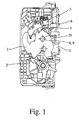
- FIG. 1 shown motor vehicle lock shows the usual closing elements latch 1 and pawl 2, which are arranged in a housing.
- the housing has an inlet slot 3, via which a not shown, usually arranged on the bodywork of the motor vehicle locking cam when slamming the vehicle door comes into engagement with the latch 1.
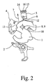
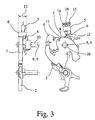
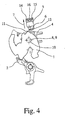
- the latch 1 is in an open position ( Fig. 2 ), into a main closed position ( Fig. 4 ) and a pre-closure ( Fig. 3 ) brought.
- a Vorsch healthy die can also be dispensed with depending on the application.
- the pawl 2 is in a sunken state, in which it holds the lock latch 1 in the main closed position and in the Vorsch.gna, and in a raised state (not shown), in which it releases the lock latch 1, brought.
- the lock mechanism is the controlled operation of the pawl 2. It is equipped with an internal operating lever, which is actuated by a door inside handle. Furthermore, a central locking lever 4 is provided which couples or decouples a titanium outside grip with the pawl 2.
- the basic structure of the in the FIGS. 1 to 5 shown motor vehicle lock can be, in particular as far as the lock mechanism, the German utility model DE 20 2005 015 687 U1 take that to the Applicant and is hereby made to the full extent the subject of the present application.
- the lock mechanism can be brought into different functional states and for this purpose at least one adjustable in different functional positions functional element 4, for example, a central locking lever 4 ,.
- a switch element 5 which serves to detect the position of at least one adjusting element 1, 4.
- a switch element 5 is preferably an electrical or electronic switch element.
- the adjusting element 1, 4 may be any adjustable element of the motor vehicle lock.
- the first adjustment element 1 is a closing element and the second adjustment element 4 is a functional element. It can be the representations in the FIGS. 1 to 6 can be seen that the actuation of the switch element 5 by the closing element 1 on the one hand and the functional element 4 on the other hand, due to their spatial proximity to the switch element 5 is particularly advantageous.
- the first adjusting element 1 is the latch 1 of the motor vehicle lock.
- the second adjusting element 4 is a central locking lever 4 of the lock mechanism or a lever coupled to the central locking lever 4.
- the central locking lever 4 in the positions “central locking-one” ( Fig. 5 ) and “central locking off” ( Fig. 2 to 4 ) and thus the lock mechanism in the functional states “central locking-one” and "central locking-off” brought.
- "central lock-on" located lock mechanism is an external operating lever decoupled from the pawl.
- "central lock-off” befindlichem lock mechanism of the external actuating lever is coupled to the pawl, so that the pawl can be excavated by means of an outside door handle.
- the second adjusting element is an unillustrated child safety lever of the lock mechanism or a lever coupled to the child safety lever.
- the child safety lever in the positions “Child Lock On” and “Child Safety Off” and thus the lock mechanism in the functional states “Child Lock On” and “Child Lock Off” can be brought.
- the second adjustment is an anti-theft lever of the lock mechanism or a lever coupled to the anti-theft lever and that the anti-theft lever in the positions “anti-theft-one” and “anti-theft-off” and thus the lock mechanism in the functional states “anti-theft” A “and” theft-off "is brought.
- the above parental control function and the above anti-theft function have the usual effects on the behavior of the vehicle lock with respect to the release of the pawl.
- the switch element 5 preferably has an actuating part 6, with which the first adjusting element 1 and the second adjusting element 4 can be brought into engagement for actuation.
- the actuating part 6 is designed in the manner of a switching flag. Basically, it may be at the operating part 6 but also a switching plunger, a shift lever to a rocker o. The like. Act. A switching flag is not necessary in every case.
- the switching lug 6 is configured here in the usual way as a bent sheet metal. Basically, but here is the application of a plastic material o. The like. Possible.
- the switch element 5 in an operating direction 7 can be actuated.
- the switch element 5 takes in its actuation in the actuation direction 7 one behind the other a first switching position ( Fig. 2, 3rd ), a second switching position ( Fig. 4 ) and a third switching position ( Fig. 5 ), wherein the first switching position is preferably designed as a rest-switching position.
- rest-switching position is always meant the switching position that occupies the switch element 5 in the non-actuated state.
- the switch element 5 is configured here and preferably in the manner of a pushbutton. So this is a touching switch.
- the switch element 5 has the basic structure of a microswitch. This too is in the FIGS. 1 to 6 shown.
- the switch element 5 is a contactless switch. All known contactless switches can be used, for example inductive switches, in particular Hall-based switches or capacitive switches. Also, MR sensors are basically applicable here. It is only necessary that with the switch element 5 used three or more switch positions are switchable.
- the switch element 5 in a part of the switching positions preferably in the first switching position and in the second switching position, both with an actuation by the first adjusting element 1 and with an actuation by the second adjusting element 4 is switchable.
- the switch element 5 in the highest switching position preferably in the third switching position, exclusively with an actuation by the second adjusting element 4 is switchable.
- the switch element 5 is not actuated, so that the switch element 5 assumes the first switching position ( Fig. 2, 3rd ).
- the in the main closing position located latch 1 operates the switch element 5 and transfers it to the second switching position ( Fig. 4 ), provided that the central locking lever 4 is in the "central locking-off" position.
- a clear detection of the functional states "central locking-on” and "central locking-off” via the third switching position is initially possible.
- the detection of the main closed position of the lock latch 1 is possible via the second switching position, provided that the functional state "central locking off” is present. If one can assume, for example, that the central locking lever 4 is mechanically adjustable only in the "central locking-on” position when the latch 1 has reached the main closed position (lock-out), the achievable with this arrangement scope of detection is sufficient.
- the switch element 5 need not be operable only in one direction of actuation. In principle, it can also be provided that the switch element 5 in two opposite directions of actuation, preferably in the manner of a rocker button, can be actuated. Preferably, the switch element 5 then assumes, starting from a first switching position when actuated in the first actuating direction, a second switching position and in the second actuating direction, a third switching position, wherein the first switching position is further preferably designed as a rest-switching position between the two other switching positions.
- the first adjusting element 1 is pivotable about a first pivot axis 8, while the second adjusting element 4 to a second pivot axis 9 is pivotable. It is advantageously such that the first pivot axis 8 and the second pivot axis 9 are identical or offset in parallel.
- the two adjusting elements 1, 4 share a pivot axis 8, 9, wherein the two adjusting elements 1, 4 are even stored on a common bearing pin 10.
- the merging of the two pivot axes 8, 9 has particular advantages, in particular with regard to the yet to be explained engagement between the adjusting elements 1, 4 and the switch element 5.
- the first adjustment element 1 and / or the second adjustment element 4 has or have a switching contour 11, 12.
- the two adjusting elements 1, 4 share a pivot axis 8, 9
- the two switching contours 11, 12 may be designed tangentially with respect to the pivot axis 8, 9. Due to the fact that the two switching contours 11, 12 execute parallel trajectories as a result, the actuation, in particular the realization of the actuating part 6, is particularly unproblematic.
- the switching contour 12 of the second adjusting element 4 is "behind" the switching contour 11 of the first adjusting element. 1
- the switching contour 11 of the first adjusting element 1 and the switching contour 12 of the second adjusting element 4 pass directly past one another. This leads to a particularly compact arrangement
- the above switching contours 11, 12 perform by the pivoting of the adjusting elements 1, 4 also pivotal movements. Conceivable, however, are also translational movements of the switching contours 11, 12. In both variants, the switching contours 11, 12 pass, as it were, on the actuating part 6, substantially perpendicular to the actuating direction 7. This "passing" can be based on the actuating part 6 from opposite sides be provided from.
- Essential to the operability of the switch element 5 by the two adjusting elements 1, 4 is the design of the operating part 6.
- the actuating part 6, in particular the switching lug 6, so parallel to the pivot axis and the pivot axes 8, 9th the adjusting elements 1, 4 extends, that it is actuated by the switching contours of the two adjusting elements 1, 4.
- This means nothing other than the width 13 ( Fig. 3 ) of the operating part 6 is dimensioned sufficiently large to ensure engagement with the switching contours 11, 12 of the two adjusting elements 1, 4.
- first adjusting element 1 and / or the second adjusting element 4 instead of a switching contour 11, 12 has a pin o.
- the pin or the like extends at least in sections parallel to the pivot axis 8, 9 of the first adjustment element 1 and of the second adjustment element 4.
- the switch element 5 has a plurality of switching outputs 14, 15, each associated with a switching position. Upon reaching a switching position then the associated switching output 14, 15 is switched.
- switching output 14, 15 it may be provided that only one switching output 14, 15 or none of the switching outputs is always switched. When passing through the first, second and third switching position is then initially no switching output 14, 15, then only a switching output 14, 15 and finally only the remaining switching output 14, 15 connected.
- a reference output 16 is provided and that the switching outputs 14, 15 are switched depending on the switching operation relative to the reference output 16. It is preferably such that the switching outputs 14, 15 are connected depending on the switching operation with the reference output 16.
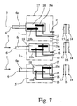
- a preferred implementation variant for the switch element shows Fig. 7 in which three different switching positions are shown among each other.
- the switch element 5 is here equipped with a housing 17 from which two switching outputs 14, 15 and a reference output 16 are led out. Furthermore, the switch element 5 is equipped with a switch plunger 6a, to which a slide 18 with two sliding contacts 18a, 18b connects.
- Switching position shown above is the first switching position in the above sense, which occupies the switch element 5 in the unactuated state.
- the switching outputs 14, 15 are separated from the reference output.
- the switching output 15 is connected to the reference output 16 via the sliding contact 18b.
- the switching output 14 remains disconnected from the reference output 16.
- Fig. 7 shown variant of a switch element 5 can be realized with simple means and shows a particularly low susceptibility to error due to the simple structure.
- the realization of a resistance coding between a switching output and a reference output of the switch element 5 can also be advantageous.
- the effective between the switching output and the reference output electrical resistance depends on the respective switching position.
- the switch element 5 can also have more than three switching positions.
- An additional switching position could for example be assigned to the detection of the prelocking position of the latch 1.
- the switch element 5 can also be actuated by an additional adjusting element or a plurality of additional adjusting elements.
- the described embodiments with only two switch elements 5 associated adjusting elements 1, 4 are merely exemplary understood.
- the switch element 5 has at least four switching positions and can be actuated by the adjusting latch lock, central locking lever and additionally anti-theft lever and switch accordingly in the at least four switching positions.
- adjusting elements 1, 4 and switching element 5 are claimed as such, without it depends on the features of the switch element 5 with at least three switching positions. It is only essential here that the switch element 5 can be actuated by a first adjusting element 1 and by a second adjusting element 4 and that the first adjusting element 1 is a closing element and that the second adjusting element 4 is a functional element is. All the preferred variants described above are also applicable to this basic structure. Reference may be made to the above statements to the full extent.
- the one operating part 6 of the switch element 5 in engagement with two adjusting elements 1, 4 can be brought.
- the actuating part 6 and thus the switch element 5 is brought into the at least three, preferably exactly three (switching) positions. These positions of the operating part 6 are seen in the operating direction 7 consecutively.
Landscapes
- Engineering & Computer Science (AREA)
- Computer Security & Cryptography (AREA)
- Lock And Its Accessories (AREA)
Applications Claiming Priority (1)
| Application Number | Priority Date | Filing Date | Title |
|---|---|---|---|
| DE200720008652 DE202007008652U1 (de) | 2007-06-18 | 2007-06-18 | Kraftfahrzeugschloß |
Publications (2)
| Publication Number | Publication Date |
|---|---|
| EP2006476A2 true EP2006476A2 (fr) | 2008-12-24 |
| EP2006476A3 EP2006476A3 (fr) | 2014-10-22 |
Family
ID=39917703
Family Applications (1)
| Application Number | Title | Priority Date | Filing Date |
|---|---|---|---|
| EP08010424.3A Withdrawn EP2006476A3 (fr) | 2007-06-18 | 2008-06-09 | Serrure de véhicule automobile |
Country Status (2)
| Country | Link |
|---|---|
| EP (1) | EP2006476A3 (fr) |
| DE (1) | DE202007008652U1 (fr) |
Cited By (5)
| Publication number | Priority date | Publication date | Assignee | Title |
|---|---|---|---|---|
| DE102012208077A1 (de) * | 2012-05-15 | 2013-11-21 | Zf Friedrichshafen Ag | Mikroschalter mit Mehrfachpositionserkennung für ein Schließsystem für ein Fahrzeug sowie ein Verfahren zur Herstellung eines Mikroschalters mit Mehrfachpositionserkennung |
| CN113622757A (zh) * | 2020-05-09 | 2021-11-09 | 开开特股份公司 | 具有防盗装置的机动车锁 |
| EP2333208B2 (fr) † | 2009-12-09 | 2023-08-16 | Brose Schliesssysteme GmbH & Co. KG | Serrure de véhicule automobile |
| WO2024041697A1 (fr) * | 2022-08-26 | 2024-02-29 | Kiekert Aktiengesellschaft | Serrure de portière de véhicule automobile |
| WO2024046530A1 (fr) * | 2022-09-02 | 2024-03-07 | Kiekert Aktiengesellschaft | Serrure de véhicule à moteur, en particulier serrure de portière de véhicule à moteur |
Families Citing this family (3)
| Publication number | Priority date | Publication date | Assignee | Title |
|---|---|---|---|---|
| DE102013106398A1 (de) * | 2013-06-19 | 2014-12-24 | Brose Fahrzeugteile Gmbh & Co. Kommanditgesellschaft, Hallstadt | Erfassungseinrichtung für die Erfassung von mechanischen Funktionszuständen eines Kraftfahrzeugschlosses |
| DE102016123328A1 (de) * | 2016-12-02 | 2018-06-07 | Witte Automotive Gmbh | Schloss |
| DE102023121030A1 (de) * | 2023-08-08 | 2025-02-13 | Kiekert Aktiengesellschaft | Kraftfahrzeug-Schloss insbesondere Kraftfahrzeug-Türschloss |
Citations (3)
| Publication number | Priority date | Publication date | Assignee | Title |
|---|---|---|---|---|
| DE19832749A1 (de) | 1998-07-21 | 2000-02-03 | Bosch Gmbh Robert | Elektromotorischer Stellantrieb für ein Kraftfahrzeugschloß |
| DE10330194A1 (de) | 2003-07-03 | 2005-01-20 | Brose Schließsysteme GmbH & Co.KG | Kraftfahrzeug-Türschloß |
| DE202005015687U1 (de) | 2005-10-05 | 2007-02-15 | BROSE SCHLIEßSYSTEME GMBH & CO. KG | Kraftfahrzeugschloß |
Family Cites Families (5)
| Publication number | Priority date | Publication date | Assignee | Title |
|---|---|---|---|---|
| DE19500284A1 (de) * | 1995-01-06 | 1996-07-18 | Bocklenberg & Motte Bomoro | Kraftfahrzeug-Türschloßeinrichtung für eine Heckdoppelklappe |
| DE19632995C2 (de) * | 1996-08-16 | 2000-08-24 | Kiekert Ag | Kraftfahrzeugtürverschluß mit einer Mehrzahl von Schaltern und einem Schalterbetätigungssystem |
| DE10360422A1 (de) * | 2003-12-19 | 2005-07-21 | Brose Schließsysteme GmbH & Co.KG | Kraftfahrzeug |
| DE102004030160A1 (de) * | 2004-06-22 | 2006-01-19 | Brose Schließsysteme GmbH & Co.KG | Kraftfahrzeugschloß mit motorischem Öffnungsantrieb |
| DE202004010218U1 (de) * | 2004-06-29 | 2004-09-09 | Kiekert Ag | Kraftfahrzeugtürverschluss |
-
2007
- 2007-06-18 DE DE200720008652 patent/DE202007008652U1/de not_active Expired - Lifetime
-
2008
- 2008-06-09 EP EP08010424.3A patent/EP2006476A3/fr not_active Withdrawn
Patent Citations (3)
| Publication number | Priority date | Publication date | Assignee | Title |
|---|---|---|---|---|
| DE19832749A1 (de) | 1998-07-21 | 2000-02-03 | Bosch Gmbh Robert | Elektromotorischer Stellantrieb für ein Kraftfahrzeugschloß |
| DE10330194A1 (de) | 2003-07-03 | 2005-01-20 | Brose Schließsysteme GmbH & Co.KG | Kraftfahrzeug-Türschloß |
| DE202005015687U1 (de) | 2005-10-05 | 2007-02-15 | BROSE SCHLIEßSYSTEME GMBH & CO. KG | Kraftfahrzeugschloß |
Cited By (5)
| Publication number | Priority date | Publication date | Assignee | Title |
|---|---|---|---|---|
| EP2333208B2 (fr) † | 2009-12-09 | 2023-08-16 | Brose Schliesssysteme GmbH & Co. KG | Serrure de véhicule automobile |
| DE102012208077A1 (de) * | 2012-05-15 | 2013-11-21 | Zf Friedrichshafen Ag | Mikroschalter mit Mehrfachpositionserkennung für ein Schließsystem für ein Fahrzeug sowie ein Verfahren zur Herstellung eines Mikroschalters mit Mehrfachpositionserkennung |
| CN113622757A (zh) * | 2020-05-09 | 2021-11-09 | 开开特股份公司 | 具有防盗装置的机动车锁 |
| WO2024041697A1 (fr) * | 2022-08-26 | 2024-02-29 | Kiekert Aktiengesellschaft | Serrure de portière de véhicule automobile |
| WO2024046530A1 (fr) * | 2022-09-02 | 2024-03-07 | Kiekert Aktiengesellschaft | Serrure de véhicule à moteur, en particulier serrure de portière de véhicule à moteur |
Also Published As
| Publication number | Publication date |
|---|---|
| EP2006476A3 (fr) | 2014-10-22 |
| DE202007008652U1 (de) | 2008-10-30 |
Similar Documents
| Publication | Publication Date | Title |
|---|---|---|
| EP1317596B1 (fr) | Serrure de porte d'automobile a mode combine de condamnation et d'ouverture centralisees | |
| DE10306610B3 (de) | Kraftfahrzeugtür und Türschloßeinheit sowie Kraftfahrzeug-Schließsystem | |
| DE19619849C2 (de) | Schloß, insbesondere für Kraftfahrzeugtüren | |
| DE19614122B4 (de) | Kraftfahrzeug-Klappenschloß oder -Türschloß | |
| EP1512814B2 (fr) | Système de verrouillage pour une porte de véhicule automobile et une poignée | |
| DE68917421T2 (de) | Verriegelung für Kraftfahrzeugtür. | |
| DE2911681C2 (de) | Elektrische Zentralverriegelungsvorrichtung für Kraftfahrzeugtüren | |
| DE69619475T2 (de) | Fahrzeugstürstellantrieb | |
| EP2006476A2 (fr) | Serrure de véhicule automobile | |
| EP2333208B1 (fr) | Serrure de véhicule automobile | |
| DE102017207295A1 (de) | Verschlussverriegelung für eine Fahrzeugtür mit Doppelzug-Lösemechanismus, der von einem Kindersicherungs-Betätigungsglied angetrieben wird | |
| DE102008018500A1 (de) | Kraftfahrzeugschloß | |
| EP1304433A1 (fr) | Serrure de la porte d'automobile avec une unité de fermeture et une unité de commande separarée l'un de l'autre | |
| DE4131891A1 (de) | Sperrvorrichtung fuer tueren eines kraftfahrzeugs | |
| WO2007022840A1 (fr) | Vehicule automobile et serrure de portiere pour une portiere d'un vehicule automobile | |
| EP1394345A2 (fr) | Serrure pour véhicule automobile | |
| EP1457625A2 (fr) | Serrure pour véhicule à ouverture assistée électriquement | |
| DE3031066A1 (de) | Zentralgesteuerte verschlusseinrichtung fuer kraftfahrzeugtueren | |
| EP1455039B1 (fr) | Dispositif d'actionnement motorisé et dispositif d'actionnement d'urgence manuel, actionnés par une poignée conjointe pour une serrure de couvercle ou de porte de véhicule | |
| DE3406116C2 (fr) | ||
| DE19742798B4 (de) | Kraftfahrzeug-Türschloß o. dgl. mit Öffnungshilfe und Kindersicherung | |
| EP1620620B1 (fr) | Levier multifonction | |
| DE102021118277A1 (de) | Kraftfahrzeugschloss | |
| EP3059361B1 (fr) | Serrure de véhicule automobile | |
| DE102017108752A1 (de) | Schloss mit Zuzieheinrichtung für ein Kraftfahrzeug |
Legal Events
| Date | Code | Title | Description |
|---|---|---|---|
| PUAI | Public reference made under article 153(3) epc to a published international application that has entered the european phase |
Free format text: ORIGINAL CODE: 0009012 |
|
| AK | Designated contracting states |
Kind code of ref document: A2 Designated state(s): AT BE BG CH CY CZ DE DK EE ES FI FR GB GR HR HU IE IS IT LI LT LU LV MC MT NL NO PL PT RO SE SI SK TR |
|
| AX | Request for extension of the european patent |
Extension state: AL BA MK RS |
|
| PUAL | Search report despatched |
Free format text: ORIGINAL CODE: 0009013 |
|
| AK | Designated contracting states |
Kind code of ref document: A3 Designated state(s): AT BE BG CH CY CZ DE DK EE ES FI FR GB GR HR HU IE IS IT LI LT LU LV MC MT NL NO PL PT RO SE SI SK TR |
|
| AX | Request for extension of the european patent |
Extension state: AL BA MK RS |
|
| RIC1 | Information provided on ipc code assigned before grant |
Ipc: E05B 17/22 20060101AFI20140924BHEP |
|
| STAA | Information on the status of an ep patent application or granted ep patent |
Free format text: STATUS: THE APPLICATION IS DEEMED TO BE WITHDRAWN |
|
| 18D | Application deemed to be withdrawn |
Effective date: 20150106 |