EP2333433A2 - Support pour un corps de chauffage de plaques et système de support - Google Patents
Support pour un corps de chauffage de plaques et système de support Download PDFInfo
- Publication number
- EP2333433A2 EP2333433A2 EP10015355A EP10015355A EP2333433A2 EP 2333433 A2 EP2333433 A2 EP 2333433A2 EP 10015355 A EP10015355 A EP 10015355A EP 10015355 A EP10015355 A EP 10015355A EP 2333433 A2 EP2333433 A2 EP 2333433A2
- Authority
- EP
- European Patent Office
- Prior art keywords
- head
- rail
- holder according
- support element
- holder
- Prior art date
- Legal status (The legal status is an assumption and is not a legal conclusion. Google has not performed a legal analysis and makes no representation as to the accuracy of the status listed.)
- Granted
Links
Images


Classifications
-
- F—MECHANICAL ENGINEERING; LIGHTING; HEATING; WEAPONS; BLASTING
- F24—HEATING; RANGES; VENTILATING
- F24D—DOMESTIC- OR SPACE-HEATING SYSTEMS, e.g. CENTRAL HEATING SYSTEMS; DOMESTIC HOT-WATER SUPPLY SYSTEMS; ELEMENTS OR COMPONENTS THEREFOR
- F24D19/00—Details
- F24D19/02—Arrangement of mountings or supports for radiators
-
- F—MECHANICAL ENGINEERING; LIGHTING; HEATING; WEAPONS; BLASTING
- F24—HEATING; RANGES; VENTILATING
- F24D—DOMESTIC- OR SPACE-HEATING SYSTEMS, e.g. CENTRAL HEATING SYSTEMS; DOMESTIC HOT-WATER SUPPLY SYSTEMS; ELEMENTS OR COMPONENTS THEREFOR
- F24D19/00—Details
- F24D19/02—Arrangement of mountings or supports for radiators
- F24D19/0203—Types of supporting means
- F24D19/0216—Supporting means having a rail
-
- F—MECHANICAL ENGINEERING; LIGHTING; HEATING; WEAPONS; BLASTING
- F24—HEATING; RANGES; VENTILATING
- F24D—DOMESTIC- OR SPACE-HEATING SYSTEMS, e.g. CENTRAL HEATING SYSTEMS; DOMESTIC HOT-WATER SUPPLY SYSTEMS; ELEMENTS OR COMPONENTS THEREFOR
- F24D19/00—Details
- F24D19/02—Arrangement of mountings or supports for radiators
- F24D19/022—Constructional details of supporting means for radiators
- F24D19/0223—Distance pieces between the radiator and the wall
-
- F—MECHANICAL ENGINEERING; LIGHTING; HEATING; WEAPONS; BLASTING
- F24—HEATING; RANGES; VENTILATING
- F24D—DOMESTIC- OR SPACE-HEATING SYSTEMS, e.g. CENTRAL HEATING SYSTEMS; DOMESTIC HOT-WATER SUPPLY SYSTEMS; ELEMENTS OR COMPONENTS THEREFOR
- F24D2220/00—Components of central heating installations excluding heat sources
- F24D2220/20—Heat consumers
- F24D2220/2009—Radiators
- F24D2220/2054—Panel radiators with or without extended convection surfaces
Definitions
- the invention also relates to a holder for a panel radiator of the type mentioned in the preamble of claim 6.
- panel radiators often do not have welded tabs by means of which they are on a wall or similar can be attached. Regardless of the presence of such tabs, however, it is essential to keep the panel radiator safely, especially in its lower part, the mounted panel radiator must be secured against lifting, moving and tilting to avoid accidents.
- VDI standard 6036 recommends values for the protection of radiators. In this case, recommendations are made as to which forces a radiator attachment should receive in each direction.
- the plate heaters already mentioned without permanently welded tabs often have loosely applied fasteners in the upper region, with which then a holder can be brought into engagement. In the lower part of the radiators are also supported. If forces now act from the side on the radiator, then the known brackets do not act sufficiently on the radiator, in order to secure it against such loads. In particular, those of the o.g. VDI standard proposed values are not respected.
- the object of the invention is therefore to develop a holder for a panel radiator without welded fastening straps, which provides good security and sufficient strength against lateral load and load from above and which may preferably meet the requirements of the VDI standard.
- this holder should also be inexpensive to produce and easy to assemble.
- Another object of the invention is to provide a support system for such radiator, which meets the above requirements. This object is solved by the characterizing features of claims 1 and 6, as well as by the claim 13, which has the following special significance.
- a support element which can be fastened to the rail. Particularly advantageous is the attachment by means of a locking screw.
- the support element comprises a head and a shaft, wherein the head with the wall-side outer surface of the plate heater can be brought into operative connection and is supported there. Due to the interaction of the rib structure of the outer surface of the plate heater and the support element lateral displacement of the plate heater is effectively avoided.
- the support element is inexpensive and easy to install. It is also possible to equip existing panel radiators with a novel holder according to the invention, so as to obtain the desired displacement safety.
- the head is formed so that it is adapted in its dimensions both the surface of a rib of the panel heater and the surface between two ribs, so a rib valley of the panel radiator. This results in significantly more possibilities of interaction of the support member with the panel radiator, so that new holes in the wall od. Like., To which the panel radiator is to be attached, can often be avoided.
- Another advantage of this embodiment is that the PlattenMapper not be disassembled extra, but only by a few millimeters must be moved if the head of the support element is not in the desired location.
- the head of the support element is designed so that it can assume two positions, namely a first position in which it comes to rest on a rib of the panel heater and a second position in which it between two ribs of the radiator, so in a Rippental, comes to the plant.
- the plate radiator which can attack the support member to produce the displacement safety. If an existing panel radiator retrofitted with the holder according to the invention, so often no new holes need to be introduced into the wall in question here.
- the head can be adapted both to the shape of a rib of the radiator and to the shape of a rib valley between two ribs of the radiator.
- the head can be moved in the two different positions.
- the anti-slip device is increased even more, as the head adapts better in the shape of the outer surface of the radiator.
- a particularly simple and practical way to bring the head in the two different positions arises when the support member and / or its head are rotatable about an axis which is perpendicular to the surface of the rail.
- the head is then adapted in the first position to the shape of a rib and in the second position to the shape of a rib valley.
- the locking screw can then be solved even with already mounted on the wall rail to rotate the support element or the head and then screw back in another position.
- means may be provided on the rail and / or on the shaft, which with counter-agents on the support element, in particular on the shaft or at the head, can be brought into operative connection to ensure assembly of the support element or the head in a defined position.
- the support element or its head is also additionally secured against accidental rotation.
- the invention according to claim 6 proposes that the lower retaining element is substantially U-shaped and has two receptacles for the lower region of the panel radiator.
- each of the receptacles is arranged in one of the U-legs.
- the U-shape of the lower holding element provides additional rigidity so that the lower support member can not be easily bent or damaged.
- the assembly of the thus formed holding element is simple, as well as the production. Due to the specially designed lower retaining element, the holder for the panel radiator is much safer, with manufacturing and assembly costs are low. This bracket will also meet the already mentioned VDI standard in terms of loads on the panel radiator from above.
- the lower holding element on its side facing the plate radiator in the direction of the recording on a chamfer is the particularly simple installation of the plate heater on the lower support member.
- the lower portion of the panel heater can then be easily placed close to the wall on the lower support member and slide along the chamfer in the direction of the receptacles on the lower support member down. Due to the bevel plate radiator is automatically guided with its lower portion in the direction of recordings. This is particularly advantageous during assembly, since a person commissioned with the assembly often can not see the lower holder during assembly. By chamfering, however, a safe and easy installation of the plate heater is given to the lower support member.
- the lower holding element and / or the sound decouplers and / or the upper holding element and / or the supporting element, in particular in the region of its head, can preferably be wholly or partly made of plastic. This is inexpensive and easy to manufacture and you get a good sound isolation between the holder of the plate heater and the plate heater itself.
- a mounting system with a holder according to claim 1 and with a holder according to claim 6 is provided.
- This system combines both advantages in itself and provides good protection of the radiator both against lateral displacement and at Loads from above.
- the mounting system also includes the corresponding modifications of the brackets according to the subclaims.
- Fig. 1 shows a plate heater 10, which has no welded fastening tabs.
- the wall-side outer surface 15 of the panel heater 10 is provided with ribs 11 and each lying between two ribs 11 Rippentälern 12.
- two rails 20 are arranged on the panel heater 10. These each have an upper retaining element 22, which holds the panel heater 10 in the upper region 13, and a lower holding member 40 which holds the panel heater 10 in the lower region 14.
- the rails 20 may be attached to a wall or the like.
- two support elements 30 are provided. These are attached to the rail 20 and are based on the wall-side outer surface 15 of the panel radiator 10 from.
- the support member 30 shown in the picture on the right is in a first position 32.1 and is supported on a rib 11, while the second support member 30, which is shown in the picture on the left, is in a second position 32.2 in a Rippental 12.
- the support elements 30 take advantage of the fact that the plate heater 10 has ribs 11.
- the support elements 30 engage here on the ribs 11 and the Rippentälern 12 and thus prevent the panel heater 10 can be moved in the direction of its width 16.
- the lower holding elements 40 engage, as in Fig. 1 shown in the lower portion 14 of the panel heater 10, while the upper support members 31 are disposed at the upper portion 14 of the panel heater 10.
- the displacement fuses 32 shown here are only one embodiment and can of course be designed differently.
- the mounting systems can also be pre-assembled as an assembly to facilitate the assembly of the panel heater 10.
- FIG. 2 shows a rail 20 according to the invention with support member 30.
- the support member 30 in this case has a shaft 31 and a head 32.
- the head 32 is located in the second position 32.2 and is thus provided for mounting in a rib valley 12 of the panel heater 10.
- the support element 30 or the head 32 should be in the in Fig. 3 position shown 32.1.
- the head 32 of the support member 30 is here adapted to the shape of a rib 11. In Fig. 2 However, the head 32 is such that it adapts to a Rippental 12.
- the shape of the head 32 in such a way that it adapts without further adjustment or without adjustment to both a rib 11 and a rib valley 12. A conversion from the first 32.1 to the second position 32.2 and back is then no longer necessary.
- the head 32 is formed so that it in the in Fig. 3 shown position, adapted to both the shape of a rib 11 of the panel heater 10 as well as the shape of a rib valley 12.
- the locking screw 35 which here completely passes through the shaft 31, still offers the advantage that it gives the support element 30 additional stability and strength.
- the means 23 may also be provided on the shaft 31, while the counter-means 34 are provided on the head 32. This is recommended in particular when, for transferring the head 32 from the first 32.1 to the second position 32.2, not the entire support element 30, but only the head 32 is adjusted.
- Fig. 6 now shows a section Fig. 1 in which it can be seen how the lower retaining element 40 is arranged on the rail 20 and how the panel heater 10 interacts with the lower retaining element 40.
- the lower holding element 40 has two receptacles 41, in which the plate heater 10 engages with its lower portion 14.
- the lower holding element 40 is U-shaped, wherein each of the receptacles 41 is arranged in one of the U-legs 42.
- On the rail 20 is the lower Retaining element 40 with two fastening screws 45 attached.
- two fastening screws 45 has the advantage that the lower retaining element 40 relative to the rail 20 can not be accidentally rotated.
- the lower support member 40 is rather securely supported on the rail 20.
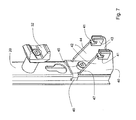
- Fig. 7 now shows the lower support member 40 and the support member 30 on a rail 20 in front view without panel radiator 10.
- the lower support member 40 and its two U-legs 42 have on its plate radiator 10 side facing 47 in the direction of the two recordings 41 a chamfer 44th on.
- This allows a particularly simple installation of the panel radiator 10.
- the panel radiator 10 needs only in the vicinity of the rail 20 attached to the lower support member 40 and is then automatically guided along the chamfer 44 in the direction of the recordings 41. He slides along the slope 44, the length of the U-legs 42 down until it comes with its lower portion 14 in the two receptacles 41 to the plant and is held there.
- the two recordings 41 here have sound decouplers 43, which consist for example of plastic. These serve on the one hand to prevent noise from the panel radiator 10 are transferred to the wall or vice versa. On the other hand, the sound decoupler 43 also serve in addition to the support of the plate heater 10 with its lower portion 14 in the receptacles 41.
- the plastic parts shown here namely have a certain elasticity, so that the lower portion 14 of the plate heater 10 can be clamped or latched in them.
- other types of acoustic decouplers 43 are possible and included in the present invention.
- the lower holding element 40 shown here has two wings 46, which in the mounted state partially surround the rail 20. As a result, a twisting of the lower retaining element 40 with respect to the rail 20 is also avoided. Furthermore, a simpler mounting of the lower holding element 40 on the rail 20 is made possible in general since the lower holding element 40 is already aligned directly on the longitudinal axis of the rail 20. The lower retaining element 40 then only has to be moved in the direction of the longitudinal axis of the rail 20 until the fastening points for example the fastening screws 45 are reached.
- the lower holding element 40 has a bevel 44 on its side facing the heating element 10 in the direction of the receptacles 41.
- the receptacles 41 are therefore also in relation to the chamfer 44 slightly offset down to avoid in particular a hooking of the panel radiator 10 to the Schallentkopplix 43.
- mounting screws 45 are provided. It has proved to be advantageous to use two fastening screws 45. To in the attachment of the lower support member 40 by the fastening screws 45, a rotation of the lower support member 40 relative to the rail 20 to avoid and to generally allow easier installation of the lower support member 40, wings 46 are provided which engage around the rail 20 in regions. Thus, the mounting of the lower support member 40 on the rail 20 can be done in a particularly simple manner and assembly errors are almost impossible.
Landscapes
- Engineering & Computer Science (AREA)
- Physics & Mathematics (AREA)
- Thermal Sciences (AREA)
- Chemical & Material Sciences (AREA)
- Combustion & Propulsion (AREA)
- Mechanical Engineering (AREA)
- General Engineering & Computer Science (AREA)
- Domestic Hot-Water Supply Systems And Details Of Heating Systems (AREA)
- Air-Conditioning For Vehicles (AREA)
- Cooling, Air Intake And Gas Exhaust, And Fuel Tank Arrangements In Propulsion Units (AREA)
Applications Claiming Priority (2)
| Application Number | Priority Date | Filing Date | Title |
|---|---|---|---|
| DE200920016752 DE202009016752U1 (de) | 2009-12-11 | 2009-12-11 | Halterung für einen Plattenheizkörper |
| DE102010015134A DE102010015134A1 (de) | 2009-12-11 | 2010-04-16 | Halterung für einen Plattenheizkörper |
Publications (3)
| Publication Number | Publication Date |
|---|---|
| EP2333433A2 true EP2333433A2 (fr) | 2011-06-15 |
| EP2333433A3 EP2333433A3 (fr) | 2011-06-22 |
| EP2333433B1 EP2333433B1 (fr) | 2016-01-13 |
Family
ID=43618702
Family Applications (1)
| Application Number | Title | Priority Date | Filing Date |
|---|---|---|---|
| EP10015355.0A Active EP2333433B1 (fr) | 2009-12-11 | 2010-12-07 | Support pour un corps de chauffage de plaques et système de support |
Country Status (2)
| Country | Link |
|---|---|
| EP (1) | EP2333433B1 (fr) |
| DE (1) | DE102010015134A1 (fr) |
Cited By (3)
| Publication number | Priority date | Publication date | Assignee | Title |
|---|---|---|---|---|
| EP2682681A3 (fr) * | 2012-07-02 | 2015-03-04 | Ulamo Holding BV | Dispositif de fixation pour fixer un corps de refroidissement ou de chauffage |
| CN106287928A (zh) * | 2016-09-26 | 2017-01-04 | 珠海格力电器股份有限公司 | 一种取暖器及其安装结构 |
| BE1026764B1 (nl) * | 2018-11-08 | 2020-06-09 | Rofix Nv | Klemelement en montageset voor het bevestigen van een verwarmingselement aan een wand of dergelijke en verwarmingselement voorzien van zo een montageset |
Family Cites Families (3)
| Publication number | Priority date | Publication date | Assignee | Title |
|---|---|---|---|---|
| DE8903907U1 (de) * | 1989-03-30 | 1990-07-26 | Sigarth Industri AB, Hillerstorp | Vorrichtung zum Befestigen von Montagekonsolen |
| DE8910010U1 (de) * | 1989-08-21 | 1989-10-12 | Müller sen., Werner, 5441 Boos | Heizkörper-Schnellspannkonsole |
| DE20107212U1 (de) * | 2000-10-06 | 2001-08-02 | Ulamo Beheer B.V., Ulft | Haltevorrichtung |
-
2010
- 2010-04-16 DE DE102010015134A patent/DE102010015134A1/de not_active Withdrawn
- 2010-12-07 EP EP10015355.0A patent/EP2333433B1/fr active Active
Non-Patent Citations (1)
| Title |
|---|
| None |
Cited By (4)
| Publication number | Priority date | Publication date | Assignee | Title |
|---|---|---|---|---|
| EP2682681A3 (fr) * | 2012-07-02 | 2015-03-04 | Ulamo Holding BV | Dispositif de fixation pour fixer un corps de refroidissement ou de chauffage |
| CN106287928A (zh) * | 2016-09-26 | 2017-01-04 | 珠海格力电器股份有限公司 | 一种取暖器及其安装结构 |
| CN106287928B (zh) * | 2016-09-26 | 2018-04-20 | 珠海格力电器股份有限公司 | 一种取暖器及其安装结构 |
| BE1026764B1 (nl) * | 2018-11-08 | 2020-06-09 | Rofix Nv | Klemelement en montageset voor het bevestigen van een verwarmingselement aan een wand of dergelijke en verwarmingselement voorzien van zo een montageset |
Also Published As
| Publication number | Publication date |
|---|---|
| EP2333433A3 (fr) | 2011-06-22 |
| EP2333433B1 (fr) | 2016-01-13 |
| DE102010015134A1 (de) | 2011-06-16 |
Similar Documents
| Publication | Publication Date | Title |
|---|---|---|
| EP3266967B1 (fr) | Fermeture à crémone | |
| DE69909153T2 (de) | Automatische Arretierung für Rolläden | |
| EP3746627B1 (fr) | Équerre de fixation pour le montage des rails supérieurs des stores vénitiens | |
| DE102011011113B4 (de) | Rahmensystem eines Partikelschutzgitters | |
| WO2017182286A1 (fr) | Système de porte coulissante | |
| DE20302139U1 (de) | Elektromotorischer Möbelantrieb | |
| EP2333433B1 (fr) | Support pour un corps de chauffage de plaques et système de support | |
| EP3241974B1 (fr) | Système pour un joint d'étanchéité, en particulier pour un joint de seuil ou pour un joint de sol s'abaissant automatiquement | |
| EP2918768A1 (fr) | Dispositif d'ombrage d'une ouverture de bâtiment | |
| EP3425155B1 (fr) | Dispositif de protection anti-pince doigt pour une porte | |
| EP2951374B1 (fr) | Pièce coulissante servant à guider une partie de meuble dans un sens de guidage sur une glissière et ferrure de meuble | |
| EP3214244B1 (fr) | Arrangement comprenant un entraînement et un dispositif de mise en mouvement pour un vantail coulissant en tant que vantail coulissant et basculant relevable ou vantail coulissant relevable | |
| DE202016106504U1 (de) | Montagewerkzeug für die Montage einer Schaltschranktür an einem Schaltschrankgehäuse und eine entsprechende Schaltschrankanordnung | |
| AT408561B (de) | Schutzzaun | |
| DE602004003430T2 (de) | Vorrichtung zur Befestigung eines Bandes an einem Flügel | |
| EP3845736B1 (fr) | Dispositif de verrouillage, dispositif de store à lamelles et procédé de fonctionnement du dispositif de verrouillage | |
| AT509757A2 (de) | Vorrichtung zum haltern eines plattenheizkörpers | |
| WO2010115544A1 (fr) | Fermeture à levier avec entraînement frontal de ses tiges de verrouillage | |
| EP2226572A2 (fr) | Dispositif de fixation d'un radiateur | |
| DE202009016752U1 (de) | Halterung für einen Plattenheizkörper | |
| DE102012019435B4 (de) | Rollladen und Panzeranbindungsmodul dafür | |
| EP2077705B1 (fr) | Support variable destiné au montage sur deux profilés de support verticaux d'un rack et procédé de montage | |
| AT411565B (de) | Vorrichtung zum befestigen eines blumenkastens an einer fensterbank einer aussenwand | |
| DE102016224882A1 (de) | Verschluss für eine hinterschnittene Beschlagnut eines Treibstangenbeschlages | |
| DE202016104904U1 (de) | System mit einem Beschlagteil und mit einem Profil |
Legal Events
| Date | Code | Title | Description |
|---|---|---|---|
| PUAI | Public reference made under article 153(3) epc to a published international application that has entered the european phase |
Free format text: ORIGINAL CODE: 0009012 |
|
| PUAL | Search report despatched |
Free format text: ORIGINAL CODE: 0009013 |
|
| AK | Designated contracting states |
Kind code of ref document: A2 Designated state(s): AL AT BE BG CH CY CZ DE DK EE ES FI FR GB GR HR HU IE IS IT LI LT LU LV MC MK MT NL NO PL PT RO RS SE SI SK SM TR |
|
| AX | Request for extension of the european patent |
Extension state: BA ME |
|
| AK | Designated contracting states |
Kind code of ref document: A3 Designated state(s): AL AT BE BG CH CY CZ DE DK EE ES FI FR GB GR HR HU IE IS IT LI LT LU LV MC MK MT NL NO PL PT RO RS SE SI SK SM TR |
|
| AX | Request for extension of the european patent |
Extension state: BA ME |
|
| 17P | Request for examination filed |
Effective date: 20111004 |
|
| 17Q | First examination report despatched |
Effective date: 20140310 |
|
| GRAP | Despatch of communication of intention to grant a patent |
Free format text: ORIGINAL CODE: EPIDOSNIGR1 |
|
| INTG | Intention to grant announced |
Effective date: 20150730 |
|
| GRAS | Grant fee paid |
Free format text: ORIGINAL CODE: EPIDOSNIGR3 |
|
| GRAA | (expected) grant |
Free format text: ORIGINAL CODE: 0009210 |
|
| AK | Designated contracting states |
Kind code of ref document: B1 Designated state(s): AL AT BE BG CH CY CZ DE DK EE ES FI FR GB GR HR HU IE IS IT LI LT LU LV MC MK MT NL NO PL PT RO RS SE SI SK SM TR |
|
| REG | Reference to a national code |
Ref country code: GB Ref legal event code: FG4D Free format text: NOT ENGLISH |
|
| REG | Reference to a national code |
Ref country code: CH Ref legal event code: EP |
|
| REG | Reference to a national code |
Ref country code: IE Ref legal event code: FG4D Free format text: LANGUAGE OF EP DOCUMENT: GERMAN |
|
| REG | Reference to a national code |
Ref country code: AT Ref legal event code: REF Ref document number: 770786 Country of ref document: AT Kind code of ref document: T Effective date: 20160215 |
|
| REG | Reference to a national code |
Ref country code: DE Ref legal event code: R096 Ref document number: 502010010921 Country of ref document: DE |
|
| REG | Reference to a national code |
Ref country code: NL Ref legal event code: FP |
|
| REG | Reference to a national code |
Ref country code: LT Ref legal event code: MG4D |
|
| PG25 | Lapsed in a contracting state [announced via postgrant information from national office to epo] |
Ref country code: HR Free format text: LAPSE BECAUSE OF FAILURE TO SUBMIT A TRANSLATION OF THE DESCRIPTION OR TO PAY THE FEE WITHIN THE PRESCRIBED TIME-LIMIT Effective date: 20160113 Ref country code: IT Free format text: LAPSE BECAUSE OF FAILURE TO SUBMIT A TRANSLATION OF THE DESCRIPTION OR TO PAY THE FEE WITHIN THE PRESCRIBED TIME-LIMIT Effective date: 20160113 Ref country code: FI Free format text: LAPSE BECAUSE OF FAILURE TO SUBMIT A TRANSLATION OF THE DESCRIPTION OR TO PAY THE FEE WITHIN THE PRESCRIBED TIME-LIMIT Effective date: 20160113 Ref country code: GR Free format text: LAPSE BECAUSE OF FAILURE TO SUBMIT A TRANSLATION OF THE DESCRIPTION OR TO PAY THE FEE WITHIN THE PRESCRIBED TIME-LIMIT Effective date: 20160414 Ref country code: ES Free format text: LAPSE BECAUSE OF FAILURE TO SUBMIT A TRANSLATION OF THE DESCRIPTION OR TO PAY THE FEE WITHIN THE PRESCRIBED TIME-LIMIT Effective date: 20160113 Ref country code: NO Free format text: LAPSE BECAUSE OF FAILURE TO SUBMIT A TRANSLATION OF THE DESCRIPTION OR TO PAY THE FEE WITHIN THE PRESCRIBED TIME-LIMIT Effective date: 20160413 |
|
| PG25 | Lapsed in a contracting state [announced via postgrant information from national office to epo] |
Ref country code: PT Free format text: LAPSE BECAUSE OF FAILURE TO SUBMIT A TRANSLATION OF THE DESCRIPTION OR TO PAY THE FEE WITHIN THE PRESCRIBED TIME-LIMIT Effective date: 20160513 Ref country code: RS Free format text: LAPSE BECAUSE OF FAILURE TO SUBMIT A TRANSLATION OF THE DESCRIPTION OR TO PAY THE FEE WITHIN THE PRESCRIBED TIME-LIMIT Effective date: 20160113 Ref country code: IS Free format text: LAPSE BECAUSE OF FAILURE TO SUBMIT A TRANSLATION OF THE DESCRIPTION OR TO PAY THE FEE WITHIN THE PRESCRIBED TIME-LIMIT Effective date: 20160513 Ref country code: LT Free format text: LAPSE BECAUSE OF FAILURE TO SUBMIT A TRANSLATION OF THE DESCRIPTION OR TO PAY THE FEE WITHIN THE PRESCRIBED TIME-LIMIT Effective date: 20160113 Ref country code: LV Free format text: LAPSE BECAUSE OF FAILURE TO SUBMIT A TRANSLATION OF THE DESCRIPTION OR TO PAY THE FEE WITHIN THE PRESCRIBED TIME-LIMIT Effective date: 20160113 Ref country code: PL Free format text: LAPSE BECAUSE OF FAILURE TO SUBMIT A TRANSLATION OF THE DESCRIPTION OR TO PAY THE FEE WITHIN THE PRESCRIBED TIME-LIMIT Effective date: 20160113 Ref country code: SE Free format text: LAPSE BECAUSE OF FAILURE TO SUBMIT A TRANSLATION OF THE DESCRIPTION OR TO PAY THE FEE WITHIN THE PRESCRIBED TIME-LIMIT Effective date: 20160113 |
|
| REG | Reference to a national code |
Ref country code: DE Ref legal event code: R097 Ref document number: 502010010921 Country of ref document: DE |
|
| PG25 | Lapsed in a contracting state [announced via postgrant information from national office to epo] |
Ref country code: DK Free format text: LAPSE BECAUSE OF FAILURE TO SUBMIT A TRANSLATION OF THE DESCRIPTION OR TO PAY THE FEE WITHIN THE PRESCRIBED TIME-LIMIT Effective date: 20160113 Ref country code: EE Free format text: LAPSE BECAUSE OF FAILURE TO SUBMIT A TRANSLATION OF THE DESCRIPTION OR TO PAY THE FEE WITHIN THE PRESCRIBED TIME-LIMIT Effective date: 20160113 |
|
| PLBE | No opposition filed within time limit |
Free format text: ORIGINAL CODE: 0009261 |
|
| STAA | Information on the status of an ep patent application or granted ep patent |
Free format text: STATUS: NO OPPOSITION FILED WITHIN TIME LIMIT |
|
| PG25 | Lapsed in a contracting state [announced via postgrant information from national office to epo] |
Ref country code: SM Free format text: LAPSE BECAUSE OF FAILURE TO SUBMIT A TRANSLATION OF THE DESCRIPTION OR TO PAY THE FEE WITHIN THE PRESCRIBED TIME-LIMIT Effective date: 20160113 Ref country code: RO Free format text: LAPSE BECAUSE OF FAILURE TO SUBMIT A TRANSLATION OF THE DESCRIPTION OR TO PAY THE FEE WITHIN THE PRESCRIBED TIME-LIMIT Effective date: 20160113 Ref country code: CZ Free format text: LAPSE BECAUSE OF FAILURE TO SUBMIT A TRANSLATION OF THE DESCRIPTION OR TO PAY THE FEE WITHIN THE PRESCRIBED TIME-LIMIT Effective date: 20160113 Ref country code: SK Free format text: LAPSE BECAUSE OF FAILURE TO SUBMIT A TRANSLATION OF THE DESCRIPTION OR TO PAY THE FEE WITHIN THE PRESCRIBED TIME-LIMIT Effective date: 20160113 |
|
| 26N | No opposition filed |
Effective date: 20161014 |
|
| PG25 | Lapsed in a contracting state [announced via postgrant information from national office to epo] |
Ref country code: SI Free format text: LAPSE BECAUSE OF FAILURE TO SUBMIT A TRANSLATION OF THE DESCRIPTION OR TO PAY THE FEE WITHIN THE PRESCRIBED TIME-LIMIT Effective date: 20160113 Ref country code: BG Free format text: LAPSE BECAUSE OF FAILURE TO SUBMIT A TRANSLATION OF THE DESCRIPTION OR TO PAY THE FEE WITHIN THE PRESCRIBED TIME-LIMIT Effective date: 20160413 |
|
| PG25 | Lapsed in a contracting state [announced via postgrant information from national office to epo] |
Ref country code: BE Free format text: LAPSE BECAUSE OF NON-PAYMENT OF DUE FEES Effective date: 20161231 |
|
| REG | Reference to a national code |
Ref country code: CH Ref legal event code: PL |
|
| GBPC | Gb: european patent ceased through non-payment of renewal fee |
Effective date: 20161207 |
|
| PG25 | Lapsed in a contracting state [announced via postgrant information from national office to epo] |
Ref country code: MC Free format text: LAPSE BECAUSE OF FAILURE TO SUBMIT A TRANSLATION OF THE DESCRIPTION OR TO PAY THE FEE WITHIN THE PRESCRIBED TIME-LIMIT Effective date: 20160113 |
|
| REG | Reference to a national code |
Ref country code: FR Ref legal event code: ST Effective date: 20170831 |
|
| REG | Reference to a national code |
Ref country code: IE Ref legal event code: MM4A |
|
| PG25 | Lapsed in a contracting state [announced via postgrant information from national office to epo] |
Ref country code: FR Free format text: LAPSE BECAUSE OF NON-PAYMENT OF DUE FEES Effective date: 20170102 Ref country code: LI Free format text: LAPSE BECAUSE OF NON-PAYMENT OF DUE FEES Effective date: 20161231 Ref country code: LU Free format text: LAPSE BECAUSE OF NON-PAYMENT OF DUE FEES Effective date: 20161207 Ref country code: CH Free format text: LAPSE BECAUSE OF NON-PAYMENT OF DUE FEES Effective date: 20161231 |
|
| PG25 | Lapsed in a contracting state [announced via postgrant information from national office to epo] |
Ref country code: IE Free format text: LAPSE BECAUSE OF NON-PAYMENT OF DUE FEES Effective date: 20161207 Ref country code: GB Free format text: LAPSE BECAUSE OF NON-PAYMENT OF DUE FEES Effective date: 20161207 |
|
| REG | Reference to a national code |
Ref country code: BE Ref legal event code: MM Effective date: 20161231 |
|
| REG | Reference to a national code |
Ref country code: AT Ref legal event code: MM01 Ref document number: 770786 Country of ref document: AT Kind code of ref document: T Effective date: 20161207 |
|
| PG25 | Lapsed in a contracting state [announced via postgrant information from national office to epo] |
Ref country code: HU Free format text: LAPSE BECAUSE OF FAILURE TO SUBMIT A TRANSLATION OF THE DESCRIPTION OR TO PAY THE FEE WITHIN THE PRESCRIBED TIME-LIMIT; INVALID AB INITIO Effective date: 20101207 Ref country code: CY Free format text: LAPSE BECAUSE OF FAILURE TO SUBMIT A TRANSLATION OF THE DESCRIPTION OR TO PAY THE FEE WITHIN THE PRESCRIBED TIME-LIMIT Effective date: 20160113 Ref country code: AT Free format text: LAPSE BECAUSE OF NON-PAYMENT OF DUE FEES Effective date: 20161207 |
|
| PG25 | Lapsed in a contracting state [announced via postgrant information from national office to epo] |
Ref country code: MK Free format text: LAPSE BECAUSE OF FAILURE TO SUBMIT A TRANSLATION OF THE DESCRIPTION OR TO PAY THE FEE WITHIN THE PRESCRIBED TIME-LIMIT Effective date: 20160113 Ref country code: TR Free format text: LAPSE BECAUSE OF FAILURE TO SUBMIT A TRANSLATION OF THE DESCRIPTION OR TO PAY THE FEE WITHIN THE PRESCRIBED TIME-LIMIT Effective date: 20160113 |
|
| PG25 | Lapsed in a contracting state [announced via postgrant information from national office to epo] |
Ref country code: MT Free format text: LAPSE BECAUSE OF FAILURE TO SUBMIT A TRANSLATION OF THE DESCRIPTION OR TO PAY THE FEE WITHIN THE PRESCRIBED TIME-LIMIT Effective date: 20160113 |
|
| PG25 | Lapsed in a contracting state [announced via postgrant information from national office to epo] |
Ref country code: AL Free format text: LAPSE BECAUSE OF FAILURE TO SUBMIT A TRANSLATION OF THE DESCRIPTION OR TO PAY THE FEE WITHIN THE PRESCRIBED TIME-LIMIT Effective date: 20160113 |
|
| PGFP | Annual fee paid to national office [announced via postgrant information from national office to epo] |
Ref country code: NL Payment date: 20211217 Year of fee payment: 12 |
|
| P01 | Opt-out of the competence of the unified patent court (upc) registered |
Effective date: 20230628 |
|
| REG | Reference to a national code |
Ref country code: NL Ref legal event code: MM Effective date: 20230101 |
|
| PG25 | Lapsed in a contracting state [announced via postgrant information from national office to epo] |
Ref country code: NL Free format text: LAPSE BECAUSE OF NON-PAYMENT OF DUE FEES Effective date: 20230101 |
|
| PGFP | Annual fee paid to national office [announced via postgrant information from national office to epo] |
Ref country code: DE Payment date: 20251127 Year of fee payment: 16 |