EP2333452A2 - Dispositif de fixation - Google Patents
Dispositif de fixation Download PDFInfo
- Publication number
- EP2333452A2 EP2333452A2 EP10189901A EP10189901A EP2333452A2 EP 2333452 A2 EP2333452 A2 EP 2333452A2 EP 10189901 A EP10189901 A EP 10189901A EP 10189901 A EP10189901 A EP 10189901A EP 2333452 A2 EP2333452 A2 EP 2333452A2
- Authority
- EP
- European Patent Office
- Prior art keywords
- fastener
- support
- mounting
- attachment
- fastening
- Prior art date
- Legal status (The legal status is an assumption and is not a legal conclusion. Google has not performed a legal analysis and makes no representation as to the accuracy of the status listed.)
- Withdrawn
Links
Images









Classifications
-
- H—ELECTRICITY
- H02—GENERATION; CONVERSION OR DISTRIBUTION OF ELECTRIC POWER
- H02S—GENERATION OF ELECTRIC POWER BY CONVERSION OF INFRARED RADIATION, VISIBLE LIGHT OR ULTRAVIOLET LIGHT, e.g. USING PHOTOVOLTAIC [PV] MODULES
- H02S20/00—Supporting structures for PV modules
- H02S20/20—Supporting structures directly fixed to an immovable object
- H02S20/22—Supporting structures directly fixed to an immovable object specially adapted for buildings
- H02S20/23—Supporting structures directly fixed to an immovable object specially adapted for buildings specially adapted for roof structures
-
- F—MECHANICAL ENGINEERING; LIGHTING; HEATING; WEAPONS; BLASTING
- F24—HEATING; RANGES; VENTILATING
- F24S—SOLAR HEAT COLLECTORS; SOLAR HEAT SYSTEMS
- F24S25/00—Arrangement of stationary mountings or supports for solar heat collector modules
- F24S25/60—Fixation means, e.g. fasteners, specially adapted for supporting solar heat collector modules
- F24S25/61—Fixation means, e.g. fasteners, specially adapted for supporting solar heat collector modules for fixing to the ground or to building structures
- F24S25/613—Fixation means, e.g. fasteners, specially adapted for supporting solar heat collector modules for fixing to the ground or to building structures in the form of bent strips or assemblies of strips; Hook-like connectors; Connectors to be mounted between building-covering elements
-
- F—MECHANICAL ENGINEERING; LIGHTING; HEATING; WEAPONS; BLASTING
- F24—HEATING; RANGES; VENTILATING
- F24S—SOLAR HEAT COLLECTORS; SOLAR HEAT SYSTEMS
- F24S25/00—Arrangement of stationary mountings or supports for solar heat collector modules
- F24S25/60—Fixation means, e.g. fasteners, specially adapted for supporting solar heat collector modules
- F24S2025/6002—Fixation means, e.g. fasteners, specially adapted for supporting solar heat collector modules by using hooks
-
- F—MECHANICAL ENGINEERING; LIGHTING; HEATING; WEAPONS; BLASTING
- F24—HEATING; RANGES; VENTILATING
- F24S—SOLAR HEAT COLLECTORS; SOLAR HEAT SYSTEMS
- F24S25/00—Arrangement of stationary mountings or supports for solar heat collector modules
- F24S25/60—Fixation means, e.g. fasteners, specially adapted for supporting solar heat collector modules
- F24S2025/6008—Fixation means, e.g. fasteners, specially adapted for supporting solar heat collector modules by using toothed elements
-
- F—MECHANICAL ENGINEERING; LIGHTING; HEATING; WEAPONS; BLASTING
- F24—HEATING; RANGES; VENTILATING
- F24S—SOLAR HEAT COLLECTORS; SOLAR HEAT SYSTEMS
- F24S80/00—Details, accessories or component parts of solar heat collectors not provided for in groups F24S10/00-F24S70/00
- F24S2080/09—Arrangements for reinforcement of solar collector elements
-
- Y—GENERAL TAGGING OF NEW TECHNOLOGICAL DEVELOPMENTS; GENERAL TAGGING OF CROSS-SECTIONAL TECHNOLOGIES SPANNING OVER SEVERAL SECTIONS OF THE IPC; TECHNICAL SUBJECTS COVERED BY FORMER USPC CROSS-REFERENCE ART COLLECTIONS [XRACs] AND DIGESTS
- Y02—TECHNOLOGIES OR APPLICATIONS FOR MITIGATION OR ADAPTATION AGAINST CLIMATE CHANGE
- Y02B—CLIMATE CHANGE MITIGATION TECHNOLOGIES RELATED TO BUILDINGS, e.g. HOUSING, HOUSE APPLIANCES OR RELATED END-USER APPLICATIONS
- Y02B10/00—Integration of renewable energy sources in buildings
- Y02B10/10—Photovoltaic [PV]
-
- Y—GENERAL TAGGING OF NEW TECHNOLOGICAL DEVELOPMENTS; GENERAL TAGGING OF CROSS-SECTIONAL TECHNOLOGIES SPANNING OVER SEVERAL SECTIONS OF THE IPC; TECHNICAL SUBJECTS COVERED BY FORMER USPC CROSS-REFERENCE ART COLLECTIONS [XRACs] AND DIGESTS
- Y02—TECHNOLOGIES OR APPLICATIONS FOR MITIGATION OR ADAPTATION AGAINST CLIMATE CHANGE
- Y02B—CLIMATE CHANGE MITIGATION TECHNOLOGIES RELATED TO BUILDINGS, e.g. HOUSING, HOUSE APPLIANCES OR RELATED END-USER APPLICATIONS
- Y02B10/00—Integration of renewable energy sources in buildings
- Y02B10/20—Solar thermal
-
- Y—GENERAL TAGGING OF NEW TECHNOLOGICAL DEVELOPMENTS; GENERAL TAGGING OF CROSS-SECTIONAL TECHNOLOGIES SPANNING OVER SEVERAL SECTIONS OF THE IPC; TECHNICAL SUBJECTS COVERED BY FORMER USPC CROSS-REFERENCE ART COLLECTIONS [XRACs] AND DIGESTS
- Y02—TECHNOLOGIES OR APPLICATIONS FOR MITIGATION OR ADAPTATION AGAINST CLIMATE CHANGE
- Y02E—REDUCTION OF GREENHOUSE GAS [GHG] EMISSIONS, RELATED TO ENERGY GENERATION, TRANSMISSION OR DISTRIBUTION
- Y02E10/00—Energy generation through renewable energy sources
- Y02E10/40—Solar thermal energy, e.g. solar towers
- Y02E10/47—Mountings or tracking
-
- Y—GENERAL TAGGING OF NEW TECHNOLOGICAL DEVELOPMENTS; GENERAL TAGGING OF CROSS-SECTIONAL TECHNOLOGIES SPANNING OVER SEVERAL SECTIONS OF THE IPC; TECHNICAL SUBJECTS COVERED BY FORMER USPC CROSS-REFERENCE ART COLLECTIONS [XRACs] AND DIGESTS
- Y02—TECHNOLOGIES OR APPLICATIONS FOR MITIGATION OR ADAPTATION AGAINST CLIMATE CHANGE
- Y02E—REDUCTION OF GREENHOUSE GAS [GHG] EMISSIONS, RELATED TO ENERGY GENERATION, TRANSMISSION OR DISTRIBUTION
- Y02E10/00—Energy generation through renewable energy sources
- Y02E10/50—Photovoltaic [PV] energy
Definitions
- the invention relates to a fastener and a method for securing an article to a substrate.
- Solar fixers are used, for example, to attach solar cells to a house roof.
- a number of solar fasteners are known in the art, see, for example DE 202009002134 U1 . DE 102005043957 B3 . DE 202009000960 U1 or DE 202007015887 U1 ,
- DE 202008016000 U1 discloses a split formed roof hook with a foot part for making a connection with a roof substructure and with a connectable to the foot hook part, which has at the other end via a connection for the attachment of a roof over the roof scaffold or a unit.
- the foot part is a cut-to-length section of an angle profile, one angle leg of which has connections for connection to the roof substructure.
- the terminals are spaced from the other angle leg.
- DE 202009001025 U1 discloses a fastening device for components, in particular for solar collectors, on a roof, consisting of a roof hook for fixing the solar collector provided with at least one substantially perpendicular to the longitudinal axis of the roof anchor on the side facing the roof side leg having a toothing, a roof anchor to Attachment to the roof with a U-shaped elevation, which has an internal toothing and a clamping piece, wherein the toothing of the roof hook engages in the toothing of the roof anchor and is positively and non-positively connected to the clamping piece.
- DE 202006009674 U1 discloses a double height adjustable roof hook which is thus useful for various battens and tile types. Its wide base plate below gives the roof holder the necessary stable hold on the rafter. Due to the variable position of the two-part boom (right, center, left), the two-piece boom can be adapted to local conditions.
- DE 202005004348 U1 discloses an aluminum roof hook with clip function for mounting solar modules on pitched roofs, which consists of a base plate and a hook, which are assembled during the assembly of the solar modules to form a roof hook.
- DE 20119478 U1 discloses a mounting bracket for roof mounting of solar modules, the complete mounting bracket consists of four parts.
- a base plate with welded U-profile designed as a perforated metal plate
- a carrying handle a key screw and a spring tension ring. This is a variable adjustability of the carrying handle to be achieved which can be adjusted with only one key screw in height, according to the roof tiles.
- a fastener for fastening an object to a base which has a fastening element and a height-adjustably mountable separate retaining clip on the fastening element.
- the headband has a mounting portion adapted for mounting the article.
- the fastener has a mounting plate for attachment to the pad.
- the headband has a mounting portion for attachment to the fastener and the fastener has a correspondingly configured support portion for supporting the mounting portion.
- An angle between the attachment portion and the mounting plate is (when the attachment portion is attached to the support portion) a substantially right angle.
- a method of attaching an article to a substrate by means of a fastener wherein in the process a mounting plate of a fastener fastener is secured to the substrate. Further, a headband of the fastener is attached to the fastener provided separately thereof height adjustable, wherein a mounting portion of the retaining clip is attached to the fastener and a correspondingly arranged support portion of the fastener the Mounting section supports. Further, the article is mounted on a mounting portion of the retaining clip. An angle between the attachment portion and the mounting plate is a substantially right angle.
- angle between the mounting portion and the mounting plate may be understood in the context of this application, in particular an angle, a defined by the mounting plate first level (especially the support plane in which the mounting plate can rest on a flat or substantially flat surface ) with a second plane defined by the attachment portion (in particular a substantially planar region of the attachment portion along which the attachment portion rests against the support portion in the assembled state).
- the angle between the attachment portion (or a planar portion thereof) and the mounting plate (or a planar portion thereof) may be equal to or substantially equal to an angle between the support portion (or a planar portion thereof) and the mounting plate (or a planar portion thereof). be.
- the attachment portion may be parallel to the support portion and disposed adjacent thereto.
- a fastener in which an angle between the attachment portion and the mounting plate can be exactly or approximately 90 °, whereby a height adjustment over a large area can be achieved while advantageously largely maintaining the mounting axis. For example, a ⁇ 5 ° deviation of the angle from a right angle may be acceptable. Simultaneously, a stable connection of headband and fastener can be achieved. Further, due to the lever ratios resulting from the attachment geometry, even a portion of the retainer (for example, the mounting portion) remote from the joint is protected from severe mechanical stress even when a heavy object is attached to the fastener. It can remain in an at least approximately vertical mounting of the retaining clip on the fastener mounting axis without change. The maintenance of the mounting axis and a possible protection against unwanted lowering of the retaining bracket or an undesirable displacement of the mounting axis facilitates the installation of the fastener even for an untrained user considerably.
- a fastener for securing an object to a base wherein the fastener has a fastening element, and a separate retaining clip that can be mounted vertically adjustable on the fastening element.
- the headband has a mounting portion adapted for mounting the article.
- the fastener has a mounting plate for attachment to the pad.
- the retaining clip has a fastening section for attachment to the fastening element and a spacer section (in particular a spacer section running parallel or substantially parallel to the mounting plate in the assembled state) and the fastening element has a correspondingly configured supporting section for supporting the fastening section.
- the spacer section merges into the attachment section via a right-angled bend (optionally rounded at the bend edge) or a substantially right-angled bend.
- An angle between the attachment portion and the mounting plate is a right angle or a substantially right angle.
- the fastener further comprises at least one connection support, which is mounted between the headband and the fastener and stabilizes a connection between the spacer portion of the retaining clip and the fastener from below supporting.
- the term "stabilizing from below” refers to a purposeful assembly of the Fastener on the pad and the retaining clip on the fastener. In such an assembly, the attachment portion extends upward and the spacer portion in the lateral direction. The spacer then has a top and a bottom major surface.
- connection support then supports the retainer by contact with the underside main surface to at least partially accommodate, for example, loads caused by the gravitational force.
- the connection support can be a component which is provided separately from the fastening element and retaining bracket or can be mounted separately on the fastening element and / or retaining bracket.
- the mounting plate and the mounting portion are oriented perpendicular to each other, wherein when used properly, the mounting plate is inclined and the mounting portion is arranged to extend perpendicular.
- the fastener may include a spacer portion between the mounting portion and the mounting portion.
- This spacer portion may have an L-shaped cross section, for example, that is configured as an angle profile.
- the spacer portion may serve to space the mounting portion of the mounting portion, which makes the fastener usable for a variety of objects to be fastened.
- the mounting portion, the mounting portion and the spacer portion may merge into each other by means of bends, which may represent bends of a common metal sheet.
- the individual sections may each be substantially planar.
- the bends can be right-angled.
- a headband can be used, which is designed to save space and can be used for a variety of applications.
- At least one of the reinforcing ribs may be attached to at least one of the bends or bend portions.
- a reinforcing rib may for example be a web element or a triangular surface element bridging two legs of a bend.
- the bending portions are exposed to particularly high forces in the mounted state, so that by providing a respective reinforcing rib at one or more bending portions, an improvement in stability can be achieved.
- At least a part of the retaining clip may have a central plate region (or a plate-like central region) and two stiffening edges arranged on both sides of the central plate region and angled relative to the central plate region. These serve the additional stabilization of the retaining clip.
- the headband can be made in such a configuration of a plate-like or sheet-like semi-finished product, which can be produced by means of bending, punching and / or other simple processing methods. The bending of edge-side end portions of a plate forms the stiffening edges with little effort, which improve the stability of the fastener when used as intended.
- the attachment portion may include means for height-adjustable attachment of the attachment portion of the retaining clip to the fastener (or at its support portion).
- a device or structure may comprise, for example, a slot or a plurality of spaced-apart individual holes.
- the fastener can be used for a variety of objects to be attached to a substrate.
- the attachment portion may further comprise at least one, preferably a plurality, positioning studs for positioning the attachment portion for attachment to the attachment member.
- positioning nubs can be displayed to a user intuitively, at which point the mounting portion is to be arranged relative to the support portion of the fastener to allow a precise and faulty mounting.
- the mounting portion may have a slot for receiving a fastening screw, whereby the object can be mounted on the mounting portion.
- the mounting portion can be attached directly or indirectly to the object.
- a slot other structures (for example one or more recesses or one or more projections) are also possible, which can serve with a corresponding element for fastening the retaining bracket to the object.
- Other mechanical and non-mechanical fastenings of the article are also possible, for example snap closures, magnetic closures, etc.
- the fixing member may have a stabilizing portion which may be arranged such that between the stabilizing portion and the supporting portion there is formed an insertion portion (for example, in the form of a trough formed therebetween) for stably inserting the fixing portion.
- an insertion portion for example, in the form of a trough formed therebetween
- the male portion may additionally provide support for the fastener to make assembly easy for the user.
- the stabilizing portion may include a first portion that is tilted (eg, perpendicular) to the mounting plate and a second portion that is at an acute angle to the first portion.
- This acute angle can be, for example, between 30 ° and 75 °, in particular between 45 ° and 65 °, and can contribute to improving the stability.
- the first portion extending substantially perpendicular to the mounting plate may form, together with the mounting portion, the male portion disposed therebetween.
- the first portion and the second portion may each be formed flat or plate-like.
- the first portion of the stabilizing portion may face the support portion, whereas the second portion of the stabilizing portion may face away from the support portion.
- the angled configuration of the second section may help to improve stability when the fastener is assembled and mounted to the pad and the article is mounted on the fastener.
- the second portion may include at least one stiffening member for stabilizing the stabilizing portion.
- the first section thus serves to define the insertion section.
- the second portion can further increase the mechanical stability of the fastener by providing stiffening beads or the like as stiffening elements.
- the stiffening elements may be attached to or formed on a surface of the second portion facing away from the first portion.
- the mounting plate may have one or more mounting holes for attachment to the pad. These one or more mounting holes may be provided in a plate-shaped portion of the mounting plate as through holes, for example, to allow a screw or rivet on any pad such as a roof surface.
- the mounting plate may have at least one stiffening element for stabilizing.
- the provision of such a stiffening element on the mounting plate increases its mechanical robustness.
- stiffening beads may be provided which may be disposed to extend between adjacent mounting holes. As a result, in the fastened state of the fastener its stability and load-bearing capacity can be further improved.
- the fastener may comprise a connection support, which is mounted between the headband and the fastener (or may be releasably attachable) and supportively stabilizes a connection between the headband and the fastener.
- a connection support By providing such a connection support, the connection of headband and fastener can be further stabilized, especially for enduring high sustained loads, as they can occur when attaching large-area solar panels to the fastener for mounting on a roof.
- the connection support between headband and fastener can be realized for example as an adjustable support screw, as a support plate or as a support wedge, as described in more detail below.
- the support section of the fastening element may have a locking section for locking the fastening section of the retaining clip.
- one or more locking elements may be provided on the locking portion.
- the support portion has a rectangular profile, which merges into the locking portion.
- a rectangular profile can be realized, for example, by means of a sheet, which may be provided in one piece with the locking portion and which may have a rectangular, in particular square shape, merely by bending or folding in cross section.
- Such a rectangular profile can improve stability and balance of the fastener.
- the locking portion may have at the level of the rectangular profile at least one locking hole for locking the attachment portion.
- the term "at the height of the rectangular profile” is to be understood that in a vertical transition region between the rectangular profile and locking portion, the locking hole can be attached.
- a locking screw can be passed substantially horizontally, for example, to lock laterally arranged a substantially perpendicular to the locking screw support screw.
- the support screw can also be passed through the rectangular profile, for example, from bottom to top. Then, an upper end portion of the support screw support an underside of the retaining bracket, whereas the locking screw can be passed horizontally through holes in mounting portion and locking portion.
- the locking portion may comprise at least one positioning recess, which may be arranged for engagement by means of the at least one positioning lug of the fastening portion.
- the positioning recess (s) can be arranged below the locking hole.
- a positioning lug of the fixing portion can spatially coincide with a corresponding positioning recess of the locking portion, thus giving a user a good assistance in performing the assembly correctly and accurately.
- the locking portion may comprise at least one positioning stud, and the Attachment section have at least one corresponding positioning recess.
- Each of the at least one positioning recess may have a plurality of engagement portions, each of which may be configured to engage the at least one positioning cam.
- the engagement portions may be connected together to form a common opening.
- recesses may be provided with multiple, for example, three or five height levels. A Positioniernoppe can engage positively in each of the recesses and fix them.
- two vertically opposed surfaces of the rectangular profile can each have at least one support recess.
- Two opposing support recesses may each be adapted to receive a support screw as a connection support for supporting the support bracket relative to the fastener.
- the fastener may comprise a foot part, which may be arranged opposite the locking portion - for example symmetrically - and may be positioned together with the locking portion and the mounting plate for resting on the base.
- This foot part may for example have a shape that is substantially mirror-symmetrical to the shape of the locking portion.
- foot part and locking portion in cross-section may substantially form a U-shape, in which at the two ends of the "U" a fold can be formed to provide a good stabilizing effect.
- a support plate may be provided as the connection support, wherein the support plate may be attached to the foot part and arranged to stabilize the support bracket relative to the fastening element.
- the support plate may be formed as an angle profile, that is, in cross-section substantially L-shaped.
- One leg of this L-shaped angle profile can be attached to the foot part, whereas the other leg can support the headband from below.
- the support plate may have at least one positioning stud.
- a plurality of positioning nubs are provided. These in turn facilitate positioning of the support plate relative to the foot part. Consequently, the foot part can also have at least one positioning recess, which can be designed to engage the at least one positioning lug of the support plate.
- the support plate can have at least one positioning recess and the foot part can have at least one positioning lug.
- the positioning recess includes a plurality of engaging portions, each of which may be adapted to be engaged by the at least one positioning nub.
- different height levels can be defined, which increases the user-friendliness of the fastener.
- the support plate may have a slot, wherein by means of passing a fastening screw through the slot and in the support plate into the support plate is fastened to the foot part. This can be done at one or more altitude levels. Instead of a slot any other fixing device is possible, which can cause fixing of the support plate and footboard.
- the fastener may according to an alternative embodiment have a support wedge as the connection support.
- Under a wedge can be understood a tapered body.
- the support wedge may be attachable to at least one support recess on a locking portion and / or on a foot portion of the fastener and be arranged to stabilize the retaining bracket relative to the fastener.
- the support wedge bridges a distance between locking section / foot part on the one hand and the headband on the other.
- the support wedge may have a bore, by means of which the support wedge can be fastened to the retaining bracket using a fastening screw.
- a bore through the support wedge may, for example, have an internal thread. Then it is approximately possible to pass through this hole, the mounting screw and anchored to another hole on the headband or the fastener.
- the support wedge may have a constant pitch. Then, the support wedge may have a prismatic shape. Alternatively, the supporting wedge may be arranged step-stepped, with which a plurality of steps can be formed.
- the headband may be formed integrally or einstoffig.
- the fastener may be integral or einstoffig. It is possible that headband and fastener are made of the same or different materials.
- the fastener can be designed as a galvanized sheet and the headband in stainless steel.
- the attachment portion may have a surface facing the mounting portion and a surface facing away from the mounting portion. These surfaces may be the two opposing major surfaces of a substantially plate-shaped attachment portion.
- the attachment section can with the surface facing the mounting portion of the retaining bracket abut the support portion. With such a mounting geometry, a bottom of a spacer portion can be brought into close spatial proximity of the support portion, whereby a basis for a space-saving attachment of a connection support is placed.
- the fastener is used as a solar fastener.
- the fastener can attach a solar module, in particular a photovoltaic system or a solar collector, on a roof of a house.
- the fastener 1 serves as a solar fastener for attaching not shown in the figure photovoltaic modules to a roof of a house.
- Fig. 1 are shown components of a fastener 1 in a disassembled state, in which a headband 2 is shown separately from a fastener 3.
- the retaining clip 2 can be mounted on the fastening element 3 in order to fasten a solar module to a roof.
- the mounting bracket 2 has a mounting portion 13 which is adapted to mount the photovoltaic module.
- the fastening element 3 has a mounting plate 60 for attachment to the roof of the house.
- the mounting bracket 2 has a mounting portion 10 for attachment to the fastener 3.
- the fastener 3 has a correspondingly configured support portion 63 which serves to support the mounting portion 10 when the mounting portion 10 is attached to the support portion 63 (the latter being incorporated in FIG Fig. 1 schematically shown by an arrow 88).
- Fig. 1 shows that the attachment portion 10 has a main surface 10b facing the mounting portion 13 and a main surface 10a facing away from the mounting portion 13.
- the fixing portion 10 abuts against the support portion 63 with the surface 10 b facing the mounting portion 13 (see FIG Fig. 2 ).
- an angle a the mounting portion 10 and the mounting plate 60 in the assembled state of the fastener 1 together include 90 °.
- a main course direction of the attachment portion 10 dashed vertical line in FIG Fig. 2
- a main direction of the mounting plate 60 dashed horizontal line in FIG Fig. 2
- a main extension direction is understood to be a substantial extension direction, of which only structurally smaller features of the
- Fastening portion 10 and the mounting plate 60 differ.
- a height adjustment that is, a vertical displacement of the mounting portion 10 while holding the mounting plate 60, therefore shifts the mounting axis in accordance with Fig. 2 not horizontal direction.
- the angle a need not be exactly 90 °, but may be, for example, between 75 ° and 105 °. It is important that the angle ⁇ deviates sufficiently little from a right angle to allow a substantially vertical mounting of the retaining clip 2 to the fastener 3, so that even when making a height adjustment, the mounting axis can be at least largely maintained.
- the headband 2 adjacent to the substantially vertical attachment portion 10 has a horizontal spacer portion 11 and a vertical spacer portion 12.
- the horizontal spacer 11 and the vertical spacer 12 clearly bridge a horizontal and a vertical distance between the mounting portion 10 and the mounting portion 13 and therefore serve as bridging portions.
- the attachment portion 10, the horizontal spacer portion 11, the vertical spacer portion 12, and the mounting portion 13 merge into one another via substantially perpendicular bends 20, 21 and 22, respectively.
- the headband 2 can be made of a metal sheet, which is correspondingly bent, stamped, milled, etc.
- two folded in a pressing operation and over the entire length of the retaining clip 2 extending lateral stiffening edges 50 are formed to increase the stability. These may, for example, have a height h of about 2 mm.
- the laterally in the insides of the Bending sections 22, 21 may be formed in order to increase the stability of the retaining clip 2.
- the attachment portion 10 of the retaining clip 2 includes a slot 31 through which a fastening screw (not shown) can be passed therethrough. This is used to attach the retaining clip 2 to the fastener 3.
- a fastening screw (not shown)
- Fig. 1 two Positioniernoppen 40 shown on the mounting portion 10, which project in the direction of the vertical spacer portion 12, are arranged side by side and can be formed, for example, during pressing of the retaining clip 2 with.
- the positioning nubs 40 may protrude approximately 0.5 cm toward the vertical spacer section 12.
- the mounting portion 13 includes a slot 30 for receiving a fastening screw (not shown) for fixing the solar system module (not shown). Such a fixation can be done directly or indirectly (via a mounting profile).
- the slot 30 has a length l of 4 cm and a width b of 1 cm.
- the fixing member 3 has a stabilizing portion 61, a supporting portion 63 and a male portion 62 formed between the stabilizing portion 61 and the supporting portion 63 except for the mounting plate 60 (which may be referred to as a roof portion since it can be fixed to the roof). All these components are formed during pressing of the fastener 3 from a piece of material.
- the mounting plate 60 has eight mounting holes 70 for receiving fastening screws (not shown), with which the solar fasteners 1 on the roof (not shown), in particular lying under the solar fasteners 1 battens (not shown), can be attached.
- a fastening tab 80 is formed, via which the solar fastener 1 with a screw (not shown) on a Roof substructure (not shown) can be attached.
- the fastening tab 80 may, for example, be inclined upwards by 45 ° or may lie in the plane of the mounting plate 60.
- the screw can be screwed in at an acute angle.
- stiffening beads 90 Between adjacent holes 70 and laterally adjacent to two outer of the holes 70 are pressed in stiffening beads 90. These may for example have a width s of 2 mm and may also have a depth of about 2 mm.
- the support portion 63 includes a, for example, perpendicular or substantially perpendicular to the plane of the mounting plate 60 extending locking portion 64, which merges at its end facing the headband 2 in a rectangular profile 65.
- three holes 71 are provided, which are arranged at the level of the underlying rectangular profile 65 and for fixing the retaining clip 2 in three possible positions using a self-tapping screw 100 (see Fig. 2 ) serve.
- the screw 100 may be referred to, for example, as a fixing or fixing screw.
- three lying under the holes 71 Aussparungspaare 41 are formed with five height levels, which serve for the positive engagement of the positioning nubs 40 of the retaining clip 2, when its mounting portion 10 are inserted into the insertion portion 63.
- Three holes 72 are formed on the top and bottom of the rectangular profile 65, which are arranged according to the positions of the holes 71 in the longitudinal side. This makes it possible, in each case two opposite holes 72 screw a support screw 101, which serves to support the retaining clip 2 from below (see Fig. 2 ).
- the insertion portion 62 includes a section corresponding to the width of the attachment portion 10 in which the opposite to the bending portion lying end of the mounting portion 10 can be inserted vertically or substantially perpendicular to the mounting plate 60 to the ground, whereby the headband 2 can be additionally held in a form-fitting manner during assembly.
- the fastening element 3 can be carried out in galvanized sheet metal.
- the headband 2 can be made for example in stainless steel.
- Fig. 2 shows a side view of the fastener 1.
- the optional reinforcing ribs 51 are in Fig. 2 Not shown.
- Fig. 3 shows the solar fastener 1 in an operating state in which the support screw 101 is partially screwed. Depending on the extent to which the support screw 101 is screwed in, the retaining bracket 2 is supported.
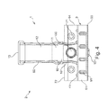
- Fig. 4 shows a side view of the fastener 1 according to Fig. 1 to Fig. 3 ,
- Fig. 5 shows a spatial view of a portion of the retaining clip.
- Fig. 6 shows a spatial view of the fastener 3 of the solar fastener 1 according to Fig. 1 ,
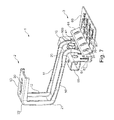
- Fig. 7 shows a spatial view of the solar fastener 1, are composed in the bracket 2 and fastener 3. According to Fig. 7 is neither a tab 80 nor reinforcing ribs 51 are provided.
- Fig. 8 shows a solar fastener 1 'according to a second embodiment of the invention, in which in turn a headband 2 and a fastener 3 are fastened to each other.
- a headband 2 and a fastener 3 are fastened to each other.
- Many of the embodiments of the embodiment according to Fig. 1 to Fig. 7 can also at the in Fig. 8 and
- Fig. 9 shown solar fasteners 1 'are used. In the following, therefore, the main differences between these two embodiments of the solar fastener 1 and 1 'are essentially described.
- a main difference between the solar fastener 1 'relative to the solar fastener 1 is that in the solar fastener 1' instead of a rectangular profile 65 with support screw 101 for stabilizing the retaining clip 2, a support plate 102 is provided.
- no rectangular profile 65 is formed on the headband 2 facing the end of the locking portion 64, but one of the shape of the locking portion 64 corresponding foot 66.
- the support plate 102 has, corresponding to the mounting portion 10, two positioning nubs 42 and a slot 32.
- the foot portion 66 has, identical to the locking portion 64, Aussparungspaare 43 with five height levels, in which the positioning nubs 42 of the support plate 102 can engage positively and fix them.
- a secure attachment of the support plate 102 on the foot part 66, in the respective height position, is achieved by means of a self-drilling fastening screw through the slot 32 in the foot part 66.
- Fig. 8 and Fig. 9 show the support plate 102 in different height levels.
- the support plate 102 is height adjustable, wherein in Fig. 8 the support plate 102 below and in Fig. 9 is positioned at the top to support the headband 102.
- FIGS. 10 to 15 a solar fastener 1 "described according to a third embodiment of the invention.
- the solar fastener 1 is also composed of a holding bracket 2 and a fastening element 3, which are provided separately from one another and which can be mounted on one another.
- a supporting wedge 103 is provided in the exemplary embodiment of the solar fastener 1 "Thus, at the end of the locking section 64 facing the retaining clip 2 there is no rectangular corner 65 but a foot section corresponding to the shape of the locking section 64 66 are formed on a substantially horizontally and parallel to the mounting plate 60 extending support portion 67 extending above the bores 71 of the locking portion 64 in the direction of the retaining clip 2 bearing recesses 104.
- the support wedge 103 may be stepped stepped on its oblique longitudinal side or have a straight pitch. The width thereof corresponds to the width of the support recesses 104. Further, a through bore 73 with internal thread (see Fig. 12 ) introduced above the longitudinal side in the wedge 103.
- the support wedge 103 can be used in the step-shaped design in fixed (and in the embodiment as a straight pitch in variable) height levels in one of the support recesses 104.
- a secure attachment of the support wedge 103 in the respective support recess 104 can be achieved by a fastening screw 120, which can be performed by a above the slot 31 arranged bore 74 and the through hole 73 of the support wedge 103.
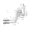
- Fig. 11 is a side view of the fastener 1 ".
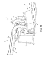
- Fig. 12 . Fig. 13 . Fig. 14 and Fig. 15 each show a detailed view of a part of the fastener 1 ".
- the solar fastener A lot of alternative designs are possible with the solar fastener. For example, all numbers of individual features (for example, number of holes) are only examples.
- the mounting portion 13 is the Example, a continuous transition of the vertical spacer portion 12 in the mounting portion 13 possible.
- An end-side flat design of the stiffening edges 50 with a pressed-in groove structure 52 may be provided, for example in order to be able to fix a fastening profile of variable height thereon.
- the mounting plate 60 it is possible to make the mounting hole 80 useful for receiving a 45 ° disk, by means of which the solar fastener can in turn be fixed against downhill forces by means of a screw which is screwed into the roof substructure.
- both fastener 3 and 2 provide bracket made of galvanized sheet metal. Components of the solar fastener may, if necessary, be coated, for example with plastic, rubber, bitumen or tar.
Landscapes
- Engineering & Computer Science (AREA)
- Architecture (AREA)
- Structural Engineering (AREA)
- Civil Engineering (AREA)
- Chemical & Material Sciences (AREA)
- Thermal Sciences (AREA)
- Physics & Mathematics (AREA)
- Combustion & Propulsion (AREA)
- Mechanical Engineering (AREA)
- General Engineering & Computer Science (AREA)
- Sustainable Energy (AREA)
- Sustainable Development (AREA)
- Life Sciences & Earth Sciences (AREA)
- Clamps And Clips (AREA)
- Helmets And Other Head Coverings (AREA)
Applications Claiming Priority (1)
| Application Number | Priority Date | Filing Date | Title |
|---|---|---|---|
| DE102009047152A DE102009047152A1 (de) | 2009-11-25 | 2009-11-25 | Befestiger |
Publications (2)
| Publication Number | Publication Date |
|---|---|
| EP2333452A2 true EP2333452A2 (fr) | 2011-06-15 |
| EP2333452A3 EP2333452A3 (fr) | 2012-03-07 |
Family
ID=43663659
Family Applications (1)
| Application Number | Title | Priority Date | Filing Date |
|---|---|---|---|
| EP10189901A Withdrawn EP2333452A3 (fr) | 2009-11-25 | 2010-11-03 | Dispositif de fixation |
Country Status (2)
| Country | Link |
|---|---|
| EP (1) | EP2333452A3 (fr) |
| DE (1) | DE102009047152A1 (fr) |
Cited By (13)
| Publication number | Priority date | Publication date | Assignee | Title |
|---|---|---|---|---|
| ITMI20111620A1 (it) * | 2011-09-08 | 2013-03-09 | Schatzer Alois S R L | Graffa di ancoraggio di lamiere a travature di coperture, tetti e simili |
| EP2573487A1 (fr) | 2011-09-22 | 2013-03-27 | Designeering S.r.l. | Structure de support pour dispositifs photovoltaïques |
| WO2013139357A1 (fr) * | 2012-03-19 | 2013-09-26 | K2 Systems Gmbh | Système de fixation pour module solaire |
| EP2653632A1 (fr) * | 2012-04-17 | 2013-10-23 | Otto Lehmann GmbH | Agencement de montage d'éléments d'accessoires de toit sur des toits inclinés de bâtiment |
| ITMI20122064A1 (it) * | 2012-12-03 | 2014-06-04 | Schatzer Alois Srl | Graffa di ancoraggio di lamiere a travature di coperture, tetti e simili |
| US8806815B1 (en) | 2013-10-15 | 2014-08-19 | Sunmodo Corporation | Adjustable solar panel tile roof mounting device |
| US8839575B1 (en) | 2013-10-15 | 2014-09-23 | Sunmodo Corporation | Adjustable solar panel tile roof mounting device |
| US9595911B2 (en) * | 2014-10-21 | 2017-03-14 | Sunrun South Llc | Tile roof mounting systems |
| DE202016102455U1 (de) | 2016-05-09 | 2017-08-10 | Eduard Kronenberg Gmbh | Montagehaken |
| CN109218483A (zh) * | 2018-11-16 | 2019-01-15 | 东莞市沃德精密机械有限公司 | 自动贴装机 |
| EP3904620A1 (fr) * | 2020-04-28 | 2021-11-03 | Eternit Österreich GmbH | Agencement de fixation |
| NL2037976A (en) * | 2023-09-11 | 2025-03-14 | Blubase B V | Device and method for mounting at least one solar panel to a roof |
| WO2025058513A1 (fr) * | 2023-09-11 | 2025-03-20 | BluBase B.V. | Dispositif et procédé de montage d'au moins un panneau solaire sur un toit |
Families Citing this family (3)
| Publication number | Priority date | Publication date | Assignee | Title |
|---|---|---|---|---|
| FR2976304B1 (fr) * | 2011-06-10 | 2013-08-23 | Saint Gobain | Dispositif de fixation pour tuile solaire |
| US10547270B2 (en) | 2016-02-12 | 2020-01-28 | Solarcity Corporation | Building integrated photovoltaic roofing assemblies and associated systems and methods |
| DE102016013153B3 (de) * | 2016-10-27 | 2018-02-22 | S:Flex Gmbh | Geteilt ausgebildeter Dachhaken für hohe Belastungen |
Citations (9)
| Publication number | Priority date | Publication date | Assignee | Title |
|---|---|---|---|---|
| DE20119478U1 (de) | 2001-11-30 | 2002-04-18 | Schnekenburger, Edgar, 78586 Deilingen | Montagebügel zur Dachbefestigung von Solarmodulen |
| DE202005004348U1 (de) | 2005-03-17 | 2005-07-28 | Kaack, Peter | Aluminium-Dachhaken mit Clipsfunktion zur Befestigung von Solarmodulen auf Schrägdächern |
| DE202006009674U1 (de) | 2006-06-21 | 2006-11-02 | Energiebau Solarstromsysteme Gmbh | Dachhalter Ziegeldach für Lorenz Montagesysteme |
| DE102005043957B3 (de) | 2005-09-15 | 2007-02-08 | Kieselbach Maschinenbauteile Gmbh | Dachhaken zur Montage von Solaranlagenmodulen auf Dächern |
| DE202007015887U1 (de) | 2007-11-14 | 2008-02-21 | Leichtmetallbau Schletter Gmbh | Befestigung für einen Dachhaken |
| DE202008016000U1 (de) | 2008-11-28 | 2009-03-05 | Haticon Ag | Geteilt ausgebildeter Dachhaken |
| DE202009000960U1 (de) | 2009-01-26 | 2009-04-09 | Ideematec Deutschland Gmbh | Dachhaken |
| DE202009002134U1 (de) | 2009-02-14 | 2009-06-10 | Energiebau Solarstromsysteme Gmbh | Dachhalter für die Systemmontage von Solarmodulen |
| DE202009001025U1 (de) | 2008-02-01 | 2009-06-18 | Vaillant Gmbh | Befestigungsvorrichtung für Bauelemente, insbesondere für Solarkollektoren |
Family Cites Families (2)
| Publication number | Priority date | Publication date | Assignee | Title |
|---|---|---|---|---|
| DE202009003745U1 (de) * | 2009-03-19 | 2009-07-16 | Haslinger, Rüdiger, Dipl.-Betriebsw. (FH) | Mehrteiliges Dachhakensystem |
| DE202010001175U1 (de) * | 2010-01-19 | 2010-04-22 | Vm Edelstahltechnik Gmbh | Dachhaken und Befestigungsmittel |
-
2009
- 2009-11-25 DE DE102009047152A patent/DE102009047152A1/de not_active Withdrawn
-
2010
- 2010-11-03 EP EP10189901A patent/EP2333452A3/fr not_active Withdrawn
Patent Citations (9)
| Publication number | Priority date | Publication date | Assignee | Title |
|---|---|---|---|---|
| DE20119478U1 (de) | 2001-11-30 | 2002-04-18 | Schnekenburger, Edgar, 78586 Deilingen | Montagebügel zur Dachbefestigung von Solarmodulen |
| DE202005004348U1 (de) | 2005-03-17 | 2005-07-28 | Kaack, Peter | Aluminium-Dachhaken mit Clipsfunktion zur Befestigung von Solarmodulen auf Schrägdächern |
| DE102005043957B3 (de) | 2005-09-15 | 2007-02-08 | Kieselbach Maschinenbauteile Gmbh | Dachhaken zur Montage von Solaranlagenmodulen auf Dächern |
| DE202006009674U1 (de) | 2006-06-21 | 2006-11-02 | Energiebau Solarstromsysteme Gmbh | Dachhalter Ziegeldach für Lorenz Montagesysteme |
| DE202007015887U1 (de) | 2007-11-14 | 2008-02-21 | Leichtmetallbau Schletter Gmbh | Befestigung für einen Dachhaken |
| DE202009001025U1 (de) | 2008-02-01 | 2009-06-18 | Vaillant Gmbh | Befestigungsvorrichtung für Bauelemente, insbesondere für Solarkollektoren |
| DE202008016000U1 (de) | 2008-11-28 | 2009-03-05 | Haticon Ag | Geteilt ausgebildeter Dachhaken |
| DE202009000960U1 (de) | 2009-01-26 | 2009-04-09 | Ideematec Deutschland Gmbh | Dachhaken |
| DE202009002134U1 (de) | 2009-02-14 | 2009-06-10 | Energiebau Solarstromsysteme Gmbh | Dachhalter für die Systemmontage von Solarmodulen |
Cited By (16)
| Publication number | Priority date | Publication date | Assignee | Title |
|---|---|---|---|---|
| ITMI20111620A1 (it) * | 2011-09-08 | 2013-03-09 | Schatzer Alois S R L | Graffa di ancoraggio di lamiere a travature di coperture, tetti e simili |
| EP2568093A1 (fr) | 2011-09-08 | 2013-03-13 | Schatzer Alois S.r.l. | Support pour fixer des pièces de tôle sur des poutres de toiture et similaires |
| EP2573487A1 (fr) | 2011-09-22 | 2013-03-27 | Designeering S.r.l. | Structure de support pour dispositifs photovoltaïques |
| WO2013139357A1 (fr) * | 2012-03-19 | 2013-09-26 | K2 Systems Gmbh | Système de fixation pour module solaire |
| EP2653632A1 (fr) * | 2012-04-17 | 2013-10-23 | Otto Lehmann GmbH | Agencement de montage d'éléments d'accessoires de toit sur des toits inclinés de bâtiment |
| ITMI20122064A1 (it) * | 2012-12-03 | 2014-06-04 | Schatzer Alois Srl | Graffa di ancoraggio di lamiere a travature di coperture, tetti e simili |
| EP2738319A1 (fr) | 2012-12-03 | 2014-06-04 | Schatzer Alois S.r.l. | Attache pour fixer des plaques métalliques à des poutres de surface de recouvrement, toits et similaire |
| US8806815B1 (en) | 2013-10-15 | 2014-08-19 | Sunmodo Corporation | Adjustable solar panel tile roof mounting device |
| US8839575B1 (en) | 2013-10-15 | 2014-09-23 | Sunmodo Corporation | Adjustable solar panel tile roof mounting device |
| US9595911B2 (en) * | 2014-10-21 | 2017-03-14 | Sunrun South Llc | Tile roof mounting systems |
| DE202016102455U1 (de) | 2016-05-09 | 2017-08-10 | Eduard Kronenberg Gmbh | Montagehaken |
| DE102017109774A1 (de) | 2016-05-09 | 2017-11-09 | Eduard Kronenberg Gmbh | Montagehaken |
| CN109218483A (zh) * | 2018-11-16 | 2019-01-15 | 东莞市沃德精密机械有限公司 | 自动贴装机 |
| EP3904620A1 (fr) * | 2020-04-28 | 2021-11-03 | Eternit Österreich GmbH | Agencement de fixation |
| NL2037976A (en) * | 2023-09-11 | 2025-03-14 | Blubase B V | Device and method for mounting at least one solar panel to a roof |
| WO2025058513A1 (fr) * | 2023-09-11 | 2025-03-20 | BluBase B.V. | Dispositif et procédé de montage d'au moins un panneau solaire sur un toit |
Also Published As
| Publication number | Publication date |
|---|---|
| EP2333452A3 (fr) | 2012-03-07 |
| DE102009047152A1 (de) | 2011-05-26 |
Similar Documents
| Publication | Publication Date | Title |
|---|---|---|
| EP2333452A2 (fr) | Dispositif de fixation | |
| DE102012011969B4 (de) | Solarmodulhalter | |
| DE102020100144B4 (de) | Montagevorrichtung für einen trägeraufbau | |
| EP2434229B1 (fr) | Crochet de toit pour le montage de modules solaires sur des toits | |
| EP2390513A1 (fr) | Dispositif destiné à lier un rail de profilé avec un autre composant | |
| DE202009003124U1 (de) | Halterung für Unterkonstruktion von Solarmodulen sowie Unterkonstruktion von Solarmodulen | |
| DE202011050810U1 (de) | Stützelement für eine Unterkonstruktion für ein Solarmodul | |
| DE102007033323B4 (de) | Befestigungseinrichtung für an einem Gestellaufbau anzuordnende flächige Bauteile, insbesondere Solarmodule | |
| WO2015110254A1 (fr) | Unité pied d'appui servant à stabiliser des panneaux solaires sur un toit plat | |
| CH718395B1 (de) | Haltevorrichtung für Solarmodule. | |
| EP2423622B1 (fr) | Dispositif de fixation avec éléments de montage et rail de support | |
| EP2372269A2 (fr) | Dispositif de liaison et agencement de profilé | |
| DE3841179C2 (fr) | ||
| DE202010012937U1 (de) | Befestigungssystem | |
| EP2554925B1 (fr) | Élément d'appui pour un module solaire | |
| EP4168721B1 (fr) | Dispositif de fixation pour fixer des modules solaires | |
| DE102021123183A1 (de) | Befestigungsvorrichtung zur Befestigung eines einen Teil eines Daches eines Gebäudes bildenden Photovoltaikmoduls am Geäude und Verbindungsvorrichtungen zur Verbindung solcher Photovoltaikmodule miteinander | |
| EP2246646A2 (fr) | crochet de couvreur | |
| WO2010130720A2 (fr) | Dispositif de support pour modules solaires | |
| DE102023101686B4 (de) | Unterkonstruktion für Photovoltaik-Module auf dem Dach | |
| EP4411275A1 (fr) | Crochet de toit | |
| DE202006006144U1 (de) | Kollektoreinheit und Befestigungsvorrichtung | |
| DE102010039843A1 (de) | Selbstbohrende Schrauben zum Befestigen von Solarpaneelen | |
| DE202011052032U1 (de) | Stützelement für ein Solarmodul | |
| DE29501224U1 (de) | Unterkonstruktion für mit Dachplatten eingedeckte Steildächer |
Legal Events
| Date | Code | Title | Description |
|---|---|---|---|
| PUAI | Public reference made under article 153(3) epc to a published international application that has entered the european phase |
Free format text: ORIGINAL CODE: 0009012 |
|
| AK | Designated contracting states |
Kind code of ref document: A2 Designated state(s): AL AT BE BG CH CY CZ DE DK EE ES FI FR GB GR HR HU IE IS IT LI LT LU LV MC MK MT NL NO PL PT RO RS SE SI SK SM TR |
|
| AX | Request for extension of the european patent |
Extension state: BA ME |
|
| PUAL | Search report despatched |
Free format text: ORIGINAL CODE: 0009013 |
|
| AK | Designated contracting states |
Kind code of ref document: A3 Designated state(s): AL AT BE BG CH CY CZ DE DK EE ES FI FR GB GR HR HU IE IS IT LI LT LU LV MC MK MT NL NO PL PT RO RS SE SI SK SM TR |
|
| AX | Request for extension of the european patent |
Extension state: BA ME |
|
| RIC1 | Information provided on ipc code assigned before grant |
Ipc: E04D 13/10 20060101ALI20120130BHEP Ipc: H01L 31/048 20060101ALI20120130BHEP Ipc: F24J 2/52 20060101AFI20120130BHEP |
|
| 17P | Request for examination filed |
Effective date: 20120827 |
|
| GRAP | Despatch of communication of intention to grant a patent |
Free format text: ORIGINAL CODE: EPIDOSNIGR1 |
|
| GRAS | Grant fee paid |
Free format text: ORIGINAL CODE: EPIDOSNIGR3 |
|
| STAA | Information on the status of an ep patent application or granted ep patent |
Free format text: STATUS: THE APPLICATION HAS BEEN WITHDRAWN |
|
| 18W | Application withdrawn |
Effective date: 20130215 |