EP2333919A2 - Agencement de câble électrique - Google Patents
Agencement de câble électrique Download PDFInfo
- Publication number
- EP2333919A2 EP2333919A2 EP10193671A EP10193671A EP2333919A2 EP 2333919 A2 EP2333919 A2 EP 2333919A2 EP 10193671 A EP10193671 A EP 10193671A EP 10193671 A EP10193671 A EP 10193671A EP 2333919 A2 EP2333919 A2 EP 2333919A2
- Authority
- EP
- European Patent Office
- Prior art keywords
- cable
- web
- branch
- housing
- main cable
- Prior art date
- Legal status (The legal status is an assumption and is not a legal conclusion. Google has not performed a legal analysis and makes no representation as to the accuracy of the status listed.)
- Granted
Links
Images


Classifications
-
- H—ELECTRICITY
- H02—GENERATION; CONVERSION OR DISTRIBUTION OF ELECTRIC POWER
- H02G—INSTALLATION OF ELECTRIC CABLES OR LINES, OR OF COMBINED OPTICAL AND ELECTRIC CABLES OR LINES
- H02G3/00—Installations of electric cables or lines or protective tubing therefor in or on buildings, equivalent structures or vehicles
-
- B—PERFORMING OPERATIONS; TRANSPORTING
- B60—VEHICLES IN GENERAL
- B60R—VEHICLES, VEHICLE FITTINGS, OR VEHICLE PARTS, NOT OTHERWISE PROVIDED FOR
- B60R16/00—Electric or fluid circuits specially adapted for vehicles and not otherwise provided for; Arrangement of elements of electric or fluid circuits specially adapted for vehicles and not otherwise provided for
- B60R16/02—Electric or fluid circuits specially adapted for vehicles and not otherwise provided for; Arrangement of elements of electric or fluid circuits specially adapted for vehicles and not otherwise provided for electric constitutive elements
- B60R16/0207—Wire harnesses
-
- H—ELECTRICITY
- H01—ELECTRIC ELEMENTS
- H01B—CABLES; CONDUCTORS; INSULATORS; SELECTION OF MATERIALS FOR THEIR CONDUCTIVE, INSULATING OR DIELECTRIC PROPERTIES
- H01B7/00—Insulated conductors or cables characterised by their form
- H01B7/08—Flat or ribbon cables
- H01B7/0853—Juxtaposed parallel wires, fixed to each other without a support layer
-
- H—ELECTRICITY
- H01—ELECTRIC ELEMENTS
- H01R—ELECTRICALLY-CONDUCTIVE CONNECTIONS; STRUCTURAL ASSOCIATIONS OF A PLURALITY OF MUTUALLY-INSULATED ELECTRICAL CONNECTING ELEMENTS; COUPLING DEVICES; CURRENT COLLECTORS
- H01R4/00—Electrically-conductive connections between two or more conductive members in direct contact, i.e. touching one another; Means for effecting or maintaining such contact; Electrically-conductive connections having two or more spaced connecting locations for conductors and using contact members penetrating insulation
- H01R4/24—Connections using contact members penetrating or cutting insulation or cable strands
- H01R4/2404—Connections using contact members penetrating or cutting insulation or cable strands the contact members having teeth, prongs, pins or needles penetrating the insulation
- H01R4/2406—Connections using contact members penetrating or cutting insulation or cable strands the contact members having teeth, prongs, pins or needles penetrating the insulation having needles or pins
Definitions
- the invention relates to an electrical cable assembly having an extruded main cable, which is provided over its length with a plurality of spaced apart, each leading to individual consumers junctions, each composed of a at least two-wire branch cable and the beginning of the branch cable branching, which seated with a trough-shaped shell on the main cable, wherein contact with the wires of the branch cable piercing or cutting contacts contact the wires of the main strand.
- Such cable assemblies are used in vehicle technology and in particular in the electrical wiring of trailer vehicles, such. B. semi-trailers. Due to the length and size of their vehicle bodywork, these vehicles not only have the usual taillight units with taillight, brake light and turn signals, but also a large number of additional lights, which are usually connected together with the standard and low beam of the towing vehicle. These auxiliary lights include side lights arranged at intervals along the body length of the vehicle so as to make the vehicle more visible from the side in the dark. Furthermore, the additional lights include position lights, which are arranged at the top of the vehicle body. The power supply of the additional lights is usually on the leading to the taillight unit harness.
- this consists of a plurality of a main cable branching individual cores, which provide the individual function lights (brake light, flashing) and the continuous light (rear light, additional lights) electrically.
- modern lighting systems to supply the function lights work z. B. with a two-wire bus line, on the positive wire not only the operating voltage for the supply of the function lights, but in addition a superimposed signal voltage is performed. This reduces the number of wires in the main cable and the wiring complexity, but the inclusion of the continuous light, ie connected together with the headlights additional lights is difficult.
- these could be controlled via the BUS system, but this would require a receiving and conversion unit for BUS signals in each additional lights, which would greatly increase the cost of additional lights.
- the main cable composed of a first strand with at least two current conductors and a parallel strand with at least one other current vein, and that the two strands are connected via a mitextrud faced web, the on those longitudinal sections on which there are channel-shaped shells, each provided with an interruption, which has at least the length of the housing portion.
- the web is longitudinally perforated, wherein preferably the perforation openings of the longitudinal perforation are shorter than the channel-shaped shells, and the non-perforated web sections have weakening zones which can be torn open under transverse forces exerted on the main cable and / or with auxiliary means are separable.
- the perforation openings are each longer than the channel-shaped shells, wherein individual of these perforation openings at the same time form the interruptions.
- the web is continuous and, viewed in the longitudinal direction, has weakening zones which can be torn open under tensile forces exerted transversely to the main cable and / or can be separated with auxiliary means.
- a wall of the branch housing extends through the interruption, the wall terminating in a triangle terminating in a tip.
- Fig. 1 shown is the photometric electrical equipment of a commercial vehicle, which is composed of a - driven - towing vehicle Z and a-pulled - trailer or semitrailer A.
- an electrical connection box 2 is attached near the front side wall 1 of the trailer vehicle A. This contains, facing the towing vehicle Z, at least one connection plug connection, via which a detachable electrical cable connection 3 can be produced with corresponding electrical connections or connecting plugs on the towing vehicle Z.
- the drawing shows several different variants of ISO connection plug connections 3a to 3d.
- a left tail lamp RL and a right tail lamp RR which are summarized in taillight units and usually the light functions of a brake light, a respective turn signal, the tail light and possibly a reversing light, a rear fog lamp or license plate lights To run.
- At least the brake unit and the turn signal unit of the taillight units RL, RR can be equipped with light-emitting diodes (LED) and corresponding ballast resistors for the light-emitting diodes instead of conventional light bulbs.
- the LEDs are usually connected in the manner of a matrix consisting of parallel LED rows, which in turn consist of several LEDs.
- each taillight housing is also a BUS signal connection of a taillight units with electrical voltage and with the ON and OFF signals for each light functions supplying BUS system.
- a central processing unit (ECU) 10 of the vehicle trailer having a processor (CPU).
- CPU central processing unit
- This can either be designed in such a way that it is the central logistics node only the lighting and lighting technology of the vehicle trailer, or the light control unit 10 may be technically linked to other control components of the vehicle, for. B. with an electronic brake control unit 4 of the vehicle.
- the central light control unit 10 is connected to the tail lamp units RL, RR via an electrical cable arrangement extending over the vehicle length.
- the main cable 11 of this cable arrangement is three-wire and contains inter alia a working as a bidirectional DC bus 7 line with positive potential, and the negative potential having ground conductor 8.
- the bus strands 7, 8 operate with DC voltage, preferably the DC voltage of the 24- Volt on-board network of the towing vehicle, wherein the DC voltage for modulating information in addition BUS signals are modulated.
- This contacting of the BUS string 7, 8 with the signal connections is preferably carried out by appropriate contacts.
- the turn signal is operated right, the corresponding, guided via the cable connection 3 and the connection plug connections circuit is closed, and this is detected by a signal evaluation of the central light control unit 10.
- the light control unit 10 then initiates the data bus 7, 8 routed via the main cable 11, a modulated signal for switching on the LED of the flashing lights of the right tail light RR.
- the BUS signal connection receives the signal and switches the LEDs of the flashing light via integrated switching elements individually or in groups depending on their execution.
- Trailer vehicles have because of their large vehicle length of often more than six meters over several side lights 20, which serve in the dark of the side marking of the vehicle body. Further, on the vehicle body front clearance lights 21 and rear position lights may be arranged, which serve the front and rear marking of the vehicle in the dark.
- the power supply of the side lights 20, the clearance lights 21 and the position lights done with DC of the 24-volt electrical system via its own, lying on positive potential plus wire 22, which is like the wires 7, 8 of the BUS strand part of the long main cable 11 ,
- the switching on of the plus wire 22 takes place by means of the control unit 10 when switching on the driving or dipped headlights in the towing vehicle, or directly by switching on the driving or dipped headlights in the towing vehicle.
- the plus wire 22 may serve as a spare line in the event of a failure or failure of the BUS line 7. If a malfunction or failure of the BUS line 7 is detected by the central light control unit 10, then the light control unit 10 closes the plus wire 22 instead of the BUS line 7 so that the BUS signals henceforth pass via the plus wire 22 to the respective tail lamp unit. This can, but does not have to go hand in hand with a targeted interruption of the disturbed BUS line 7.
- the replacement of the BUS line 7 by carried in the same main cable 11 plus wire 22 of the vehicle lighting requires that the plus wire 22 over the entire electrical conduction extends between the BUS signal connection 6A of the light control unit and the BUS signal connections of the taillight units.
- each plus wire 22 is extended on the one hand to the place of signal application in the control unit side bus signal connection 6A, and on the other hand to the place of the signal tap in the tail light side bus signal connection 6B, as in Fig. 1 the line sections 22A and 22B of the plus wire 22 play.
- the switching of the BUS signals from the wire 7 of the BUS strand to the adjacent plus wire 22 has for the regular, the supply of the side lights 20, the front Clearance lights 21 and the rear position lights with DC voltage supply voltage has no effect, as this continues to take place. Rather, it is even of advantage that the emergency operation for the driver is at least recognizable from the fact that even with the driving or dipped headlights off, the side lights 20, clearance lights 21 and position lights burn.
- the driver can be displayed separately switching to emergency mode, for example by a switched from the light control unit 10 warning notice on the instrument panel of towing vehicle Z or to the connection box 2 of the trailer.
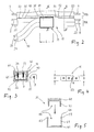
- each branch 15 is located in a branch housing 31, from which a branch cable 30 with wires 33, 34 leads to the respective side light 20. Details in the area of each branch 15 are described below with reference to FIGS. 2 to 7 explained.
- the main cable 11 is made in one piece of a first strand 11A, in the plastic, the positive wire 22 and the ground conductor 8 are embedded, and a parallel strand 11 B together. Embedded in the parallel strand 11 B runs to the taillight unit RL or RR leading, BUS signals transmitting vein 7 of the bidirectional BUS. According to Fig. 4 and Fig. 7 the two strands 11A, 11 B of the main cable 11 are normally connected to each other via a web 35.
- the web 35 is extruded in the extrusion of the insulating plastic of the main cable 11, wherein the cross-sectional thickness d of the web 35 is less than the cross-sectional thickness D of the strand 11A and the parallel strand 11 B.
- the electrical contacting of the two wires 33, 34 of the branch cable 30 is located within the branch housing 31.
- the branch housing 31 consists of a first housing part 41 and a second housing part 42.
- the first housing part 41 is designed shell-shaped. It therefore forms a housing region 44 which opens in a channel-shaped manner with respect to the first strand 11A. This region of the branching housing is therefore designed such that it encloses the strand 11A, in which the strands to be contacted are located, on three sides.
- the second housing part 42 is set against the shell 44 of the first housing part 41, whereby the two housing parts 41, 42 together enclose the strand 11A of the main cable 11 over the housing length L.
- Fig. 5 let the housing parts 41, 42 permanently connect with one another by means of integrally formed latches 47.
- two pointed lancing piercing contacts 45 or two sharp cutting edge having cutting contacts are fixed, which are electrically connected within the housing with the wires 33, 34 of the branch cable 30.
- the tips or cutting the piercing or cutting contacts 45 penetrate into the ground conductor 8 and into the positive wire 22, and thus provide the required for powering the side lights electrical contact of the wires 33, 34 of the branch cable 30 to the ground conductor 8 and the plus wire 22 ago.
- the web 35 can be designed continuously. Preferably, however, is the illustrated, interrupted embodiment, in which the web 35 is provided in the cable longitudinal direction with a plurality of openings, so perforations 50, between which web portions 52 remain.
- the length of the individual perforation openings 50 is less than the housing length L.
- an interruption 51 of the web length must therefore be created, through which interruption 51 the wall 43 of the branch housing 31 can extend.
- the interruption 51 must be equal to or longer than the housing length L of the cup-shaped housing portion 44. This can be accomplished in a simple manner by separating all the web sections 52 present in the region of the length L. This can be done by hand applied to the strands 11A, 11B tensile forces transverse to the main cable 11, ie by deliberate tearing. The rupture of the web portions 52 is facilitated by having these weakened zones 53 again with reduced material thickness.
- the web sections 52 can also be severed by means of technical aids.
- the lateral wall 43 of each of the housing parts 41, 42 sharp-edged be designed similar to a cutting edge.
- the Fig. 5 indicates that the lateral wall 43 of the one housing part 42 in the direction of the other housing part 41 out in an acute-angled, that ends in a sharp-edged tip 48 triangle ends.
- integrally formed on the branch housing 31 cutting edge occurs, for. B. at a strong depression of the housing part 41 on the strand 11A by itself to a severing of all arranged on the longitudinal portion L web portions 52, which is a particularly advantageous embodiment in terms of production technology.
- This electrical cable arrangement can, with a simple structure, any other additional lights 20, 21 connect in a simple manner to the main cable 11. This can also be done at any point along the main cable 11, which is why the cable assembly is very flexible despite the consistently shaped wires of the main cable, such as different types of vehicles.
- the cable arrangement is suitable for the electrical connection of such additional consumers, which likewise have to be supplied via the positive wire 22 with continuous current or longer switched-on current.
Landscapes
- Engineering & Computer Science (AREA)
- Architecture (AREA)
- Civil Engineering (AREA)
- Structural Engineering (AREA)
- Mechanical Engineering (AREA)
- Lighting Device Outwards From Vehicle And Optical Signal (AREA)
- Multi-Conductor Connections (AREA)
Applications Claiming Priority (1)
| Application Number | Priority Date | Filing Date | Title |
|---|---|---|---|
| DE102009044809A DE102009044809A1 (de) | 2009-12-08 | 2009-12-08 | Elektrische Kabelanordnung |
Publications (3)
| Publication Number | Publication Date |
|---|---|
| EP2333919A2 true EP2333919A2 (fr) | 2011-06-15 |
| EP2333919A3 EP2333919A3 (fr) | 2013-08-14 |
| EP2333919B1 EP2333919B1 (fr) | 2014-06-11 |
Family
ID=43858294
Family Applications (1)
| Application Number | Title | Priority Date | Filing Date |
|---|---|---|---|
| EP10193671.4A Not-in-force EP2333919B1 (fr) | 2009-12-08 | 2010-12-03 | Agencement de câble électrique |
Country Status (2)
| Country | Link |
|---|---|
| EP (1) | EP2333919B1 (fr) |
| DE (1) | DE102009044809A1 (fr) |
Cited By (2)
| Publication number | Priority date | Publication date | Assignee | Title |
|---|---|---|---|---|
| CN103946070A (zh) * | 2011-11-21 | 2014-07-23 | 矢崎总业株式会社 | 用于制造线束的方法和用于制造并布置该线束的方法 |
| EP2607653A3 (fr) * | 2011-12-22 | 2017-10-11 | Rolls-Royce plc | Ensemble de câblage électrique avec plan de masse pour moteurs à turbine à gaz |
Families Citing this family (4)
| Publication number | Priority date | Publication date | Assignee | Title |
|---|---|---|---|---|
| DE102011105970A1 (de) * | 2011-06-29 | 2013-01-03 | Burg Silvergreen Gmbh | Leitungsanordnung |
| US8870590B2 (en) | 2012-05-25 | 2014-10-28 | Amphenol Ltw Technology Co., Ltd. | Electrical-conductive assembly for signal cable and connecitng line |
| US11601575B2 (en) | 2018-09-14 | 2023-03-07 | Gopro, Inc. | Electrical connectivity between detachable components |
| DE102019101889A1 (de) * | 2019-01-25 | 2020-07-30 | Wabco Gmbh | Verkabelung und Ansteuerungsmodul |
Family Cites Families (12)
| Publication number | Priority date | Publication date | Assignee | Title |
|---|---|---|---|---|
| DE7024588U (de) * | 1970-07-01 | 1971-05-06 | Diehl | Vielleiterkabel für Schwachstrom |
| JPS59201313A (ja) * | 1983-04-21 | 1984-11-14 | モレツクス・インコ−ポレ−テツド | ノツチなし電気リボンケ−ブル |
| DE3405302C2 (de) * | 1984-02-15 | 1986-10-23 | Wolfgang Dipl.-Ing. 2351 Trappenkamp Freitag | Vierpoliges elektrisches Flachband-Lautsprecherkabel |
| FR2665803B1 (fr) * | 1990-08-09 | 1993-06-18 | Labinal | Connecteur de derivation. |
| CA2145608C (fr) * | 1994-03-29 | 2000-06-20 | Kazuya Akashi | Faisceau de cables et methode de fabrication connexe |
| US5483020A (en) * | 1994-04-12 | 1996-01-09 | W. L. Gore & Associates, Inc. | Twin-ax cable |
| GB9415551D0 (en) * | 1994-08-02 | 1994-09-21 | Amphenol Ltd | Flat flexible conductor cable |
| JP2002246090A (ja) * | 2001-02-13 | 2002-08-30 | Sunx Ltd | 並列多芯ケーブル用コネクタ |
| JP3984536B2 (ja) * | 2002-12-04 | 2007-10-03 | 株式会社オートネットワーク技術研究所 | シールドケーブル及びその分岐接続方法 |
| DE102004036341A1 (de) * | 2004-07-27 | 2006-03-23 | Schmitz Gotha Fahrzeugwerke Gmbh | Beleuchtungsanordnung eines Lastfahrzeugs, insbesondere eines Anhängers, sowie Kabelverbinder hierfür |
| DE102006039604A1 (de) * | 2006-08-24 | 2008-02-28 | Weidmüller Interface GmbH & Co. KG | Kabel, Anschlußeinrichtung mit Kabel und Verfahren zur Herstellung des Kabels |
| DE202006019520U1 (de) * | 2006-12-21 | 2008-04-30 | Weidmüller Interface GmbH & Co. KG | Anschlussvorrichtung für Mehrleiterkabel |
-
2009
- 2009-12-08 DE DE102009044809A patent/DE102009044809A1/de not_active Withdrawn
-
2010
- 2010-12-03 EP EP10193671.4A patent/EP2333919B1/fr not_active Not-in-force
Non-Patent Citations (1)
| Title |
|---|
| None |
Cited By (3)
| Publication number | Priority date | Publication date | Assignee | Title |
|---|---|---|---|---|
| CN103946070A (zh) * | 2011-11-21 | 2014-07-23 | 矢崎总业株式会社 | 用于制造线束的方法和用于制造并布置该线束的方法 |
| CN103946070B (zh) * | 2011-11-21 | 2016-01-20 | 矢崎总业株式会社 | 用于制造线束的方法和用于制造并布置该线束的方法 |
| EP2607653A3 (fr) * | 2011-12-22 | 2017-10-11 | Rolls-Royce plc | Ensemble de câblage électrique avec plan de masse pour moteurs à turbine à gaz |
Also Published As
| Publication number | Publication date |
|---|---|
| DE102009044809A1 (de) | 2011-06-09 |
| EP2333919B1 (fr) | 2014-06-11 |
| EP2333919A3 (fr) | 2013-08-14 |
Similar Documents
| Publication | Publication Date | Title |
|---|---|---|
| DE69416602T2 (de) | Leiterverbindung und werkzeug sowie verfahren zur herstellung der verbindung | |
| EP2333919B1 (fr) | Agencement de câble électrique | |
| DE4405083C2 (de) | Meßinstrumentenmodul | |
| DE4424471C2 (de) | Elektrisches Anhängeranschlußgerät für ein Zugfahrzeug | |
| EP2287043B1 (fr) | Système d'éclairage de véhicule doté d'une détection et d'un affichage de panne d'une lampe de véhicule à DEL | |
| DE2809763A1 (de) | Energieversorgungsanlage, insbesondere fuer kraftfahrzeuge | |
| DE2323620C3 (de) | Zentraleinheit für die elektrische Ausrüstung eines Kraftfahrzeuges | |
| EP3325723B1 (fr) | Marquage routier électriquement conducteur et rue avec un marquage routier électriquement conducteur | |
| EP0968880B1 (fr) | Dispositif pour alimenter en courant et tension les éléments des freins d'une remorque de véhicule | |
| EP2945465B1 (fr) | Circuit électronique pour un affichage de surveillance d'angle mort et méthode de fabrication correspondant | |
| DE102009044055A1 (de) | Elektrische Anschlusseinheit für ein Anhängerfahrzeug | |
| DE4422393A1 (de) | Kraftfahrzeugbeleuchtungsanordnung | |
| DE2014959B2 (de) | Kabelbaum, insbesondere fuer die verwendung in kraftfahrzeugen, und verfahren zu seiner herstellung | |
| DE102011050407B4 (de) | Fahrzeugheckleuchte mit akustischem Rückfahrwarner | |
| DE10355046A1 (de) | Steuereinrichtung für Außenlichteinheiten von Fahrzeugen, insbesondere Kraftfahrzeugen | |
| DE102021117174B4 (de) | Hubladebühne und Verfahren zur Fahrzeugbeleuchtung | |
| DE202005017151U1 (de) | Steuerungsvorrichtung für Anhänger und Fahrradträger | |
| DE69504389T2 (de) | Lenksäule für ein Kraftfahrzeug | |
| DE102009044056A1 (de) | Fahrzeugbeleuchtungssystem mit einer Lichtsteuereinheit | |
| EP3686056A1 (fr) | Câblage et module de commande pour remorque | |
| EP2384935B1 (fr) | Procédé de commutation d'un éclairage de véhicule | |
| DE2931903A1 (de) | Richtungsanzeigeschalter fuer strassenfahrzeuge | |
| DE102004036340A1 (de) | Heckleuchtenanordnung für Lastfahrzeuge, insbesondere Anhänger | |
| EP2428400A2 (fr) | Système d'éclairage de véhicule doté d'un circuit de secours | |
| EP1690735B1 (fr) | Dispositif d'éclairage pour un véhicule |
Legal Events
| Date | Code | Title | Description |
|---|---|---|---|
| PUAI | Public reference made under article 153(3) epc to a published international application that has entered the european phase |
Free format text: ORIGINAL CODE: 0009012 |
|
| AK | Designated contracting states |
Kind code of ref document: A2 Designated state(s): AL AT BE BG CH CY CZ DE DK EE ES FI FR GB GR HR HU IE IS IT LI LT LU LV MC MK MT NL NO PL PT RO RS SE SI SK SM TR |
|
| AX | Request for extension of the european patent |
Extension state: BA ME |
|
| PUAL | Search report despatched |
Free format text: ORIGINAL CODE: 0009013 |
|
| AK | Designated contracting states |
Kind code of ref document: A3 Designated state(s): AL AT BE BG CH CY CZ DE DK EE ES FI FR GB GR HR HU IE IS IT LI LT LU LV MC MK MT NL NO PL PT RO RS SE SI SK SM TR |
|
| AX | Request for extension of the european patent |
Extension state: BA ME |
|
| RIC1 | Information provided on ipc code assigned before grant |
Ipc: H01R 4/24 20060101ALI20130705BHEP Ipc: H02G 3/00 20060101AFI20130705BHEP Ipc: H01B 7/00 20060101ALI20130705BHEP Ipc: B60R 16/02 20060101ALI20130705BHEP Ipc: H01R 12/61 20110101ALI20130705BHEP |
|
| 17P | Request for examination filed |
Effective date: 20131122 |
|
| RBV | Designated contracting states (corrected) |
Designated state(s): AL AT BE BG CH CY CZ DE DK EE ES FI FR GB GR HR HU IE IS IT LI LT LU LV MC MK MT NL NO PL PT RO RS SE SI SK SM TR |
|
| GRAP | Despatch of communication of intention to grant a patent |
Free format text: ORIGINAL CODE: EPIDOSNIGR1 |
|
| RIC1 | Information provided on ipc code assigned before grant |
Ipc: H01R 12/61 20110101ALI20131209BHEP Ipc: H02G 3/00 20060101AFI20131209BHEP Ipc: H01R 4/24 20060101ALI20131209BHEP Ipc: H01B 7/00 20060101ALI20131209BHEP Ipc: B60R 16/02 20060101ALI20131209BHEP |
|
| INTG | Intention to grant announced |
Effective date: 20140116 |
|
| GRAS | Grant fee paid |
Free format text: ORIGINAL CODE: EPIDOSNIGR3 |
|
| GRAA | (expected) grant |
Free format text: ORIGINAL CODE: 0009210 |
|
| AK | Designated contracting states |
Kind code of ref document: B1 Designated state(s): AL AT BE BG CH CY CZ DE DK EE ES FI FR GB GR HR HU IE IS IT LI LT LU LV MC MK MT NL NO PL PT RO RS SE SI SK SM TR |
|
| REG | Reference to a national code |
Ref country code: GB Ref legal event code: FG4D Free format text: NOT ENGLISH |
|
| REG | Reference to a national code |
Ref country code: CH Ref legal event code: EP |
|
| REG | Reference to a national code |
Ref country code: IE Ref legal event code: FG4D Free format text: LANGUAGE OF EP DOCUMENT: GERMAN |
|
| REG | Reference to a national code |
Ref country code: AT Ref legal event code: REF Ref document number: 672639 Country of ref document: AT Kind code of ref document: T Effective date: 20140715 |
|
| REG | Reference to a national code |
Ref country code: DE Ref legal event code: R096 Ref document number: 502010007173 Country of ref document: DE Effective date: 20140724 |
|
| PG25 | Lapsed in a contracting state [announced via postgrant information from national office to epo] |
Ref country code: FI Free format text: LAPSE BECAUSE OF FAILURE TO SUBMIT A TRANSLATION OF THE DESCRIPTION OR TO PAY THE FEE WITHIN THE PRESCRIBED TIME-LIMIT Effective date: 20140611 Ref country code: GR Free format text: LAPSE BECAUSE OF FAILURE TO SUBMIT A TRANSLATION OF THE DESCRIPTION OR TO PAY THE FEE WITHIN THE PRESCRIBED TIME-LIMIT Effective date: 20140912 Ref country code: LT Free format text: LAPSE BECAUSE OF FAILURE TO SUBMIT A TRANSLATION OF THE DESCRIPTION OR TO PAY THE FEE WITHIN THE PRESCRIBED TIME-LIMIT Effective date: 20140611 Ref country code: NO Free format text: LAPSE BECAUSE OF FAILURE TO SUBMIT A TRANSLATION OF THE DESCRIPTION OR TO PAY THE FEE WITHIN THE PRESCRIBED TIME-LIMIT Effective date: 20140911 |
|
| REG | Reference to a national code |
Ref country code: NL Ref legal event code: VDEP Effective date: 20140611 |
|
| REG | Reference to a national code |
Ref country code: LT Ref legal event code: MG4D |
|
| PG25 | Lapsed in a contracting state [announced via postgrant information from national office to epo] |
Ref country code: HR Free format text: LAPSE BECAUSE OF FAILURE TO SUBMIT A TRANSLATION OF THE DESCRIPTION OR TO PAY THE FEE WITHIN THE PRESCRIBED TIME-LIMIT Effective date: 20140611 Ref country code: SE Free format text: LAPSE BECAUSE OF FAILURE TO SUBMIT A TRANSLATION OF THE DESCRIPTION OR TO PAY THE FEE WITHIN THE PRESCRIBED TIME-LIMIT Effective date: 20140611 Ref country code: LV Free format text: LAPSE BECAUSE OF FAILURE TO SUBMIT A TRANSLATION OF THE DESCRIPTION OR TO PAY THE FEE WITHIN THE PRESCRIBED TIME-LIMIT Effective date: 20140611 Ref country code: RS Free format text: LAPSE BECAUSE OF FAILURE TO SUBMIT A TRANSLATION OF THE DESCRIPTION OR TO PAY THE FEE WITHIN THE PRESCRIBED TIME-LIMIT Effective date: 20140611 |
|
| REG | Reference to a national code |
Ref country code: DE Ref legal event code: R082 Ref document number: 502010007173 Country of ref document: DE Representative=s name: BUNGARTZ CHRISTOPHERSEN PARTNERSCHAFT MBB PATE, DE |
|
| PG25 | Lapsed in a contracting state [announced via postgrant information from national office to epo] |
Ref country code: CZ Free format text: LAPSE BECAUSE OF FAILURE TO SUBMIT A TRANSLATION OF THE DESCRIPTION OR TO PAY THE FEE WITHIN THE PRESCRIBED TIME-LIMIT Effective date: 20140611 Ref country code: RO Free format text: LAPSE BECAUSE OF FAILURE TO SUBMIT A TRANSLATION OF THE DESCRIPTION OR TO PAY THE FEE WITHIN THE PRESCRIBED TIME-LIMIT Effective date: 20140611 Ref country code: EE Free format text: LAPSE BECAUSE OF FAILURE TO SUBMIT A TRANSLATION OF THE DESCRIPTION OR TO PAY THE FEE WITHIN THE PRESCRIBED TIME-LIMIT Effective date: 20140611 Ref country code: ES Free format text: LAPSE BECAUSE OF FAILURE TO SUBMIT A TRANSLATION OF THE DESCRIPTION OR TO PAY THE FEE WITHIN THE PRESCRIBED TIME-LIMIT Effective date: 20140611 Ref country code: PT Free format text: LAPSE BECAUSE OF FAILURE TO SUBMIT A TRANSLATION OF THE DESCRIPTION OR TO PAY THE FEE WITHIN THE PRESCRIBED TIME-LIMIT Effective date: 20141013 Ref country code: SK Free format text: LAPSE BECAUSE OF FAILURE TO SUBMIT A TRANSLATION OF THE DESCRIPTION OR TO PAY THE FEE WITHIN THE PRESCRIBED TIME-LIMIT Effective date: 20140611 |
|
| PG25 | Lapsed in a contracting state [announced via postgrant information from national office to epo] |
Ref country code: NL Free format text: LAPSE BECAUSE OF FAILURE TO SUBMIT A TRANSLATION OF THE DESCRIPTION OR TO PAY THE FEE WITHIN THE PRESCRIBED TIME-LIMIT Effective date: 20140611 Ref country code: IS Free format text: LAPSE BECAUSE OF FAILURE TO SUBMIT A TRANSLATION OF THE DESCRIPTION OR TO PAY THE FEE WITHIN THE PRESCRIBED TIME-LIMIT Effective date: 20141011 Ref country code: PL Free format text: LAPSE BECAUSE OF FAILURE TO SUBMIT A TRANSLATION OF THE DESCRIPTION OR TO PAY THE FEE WITHIN THE PRESCRIBED TIME-LIMIT Effective date: 20140611 |
|
| REG | Reference to a national code |
Ref country code: DE Ref legal event code: R097 Ref document number: 502010007173 Country of ref document: DE |
|
| PLBE | No opposition filed within time limit |
Free format text: ORIGINAL CODE: 0009261 |
|
| STAA | Information on the status of an ep patent application or granted ep patent |
Free format text: STATUS: NO OPPOSITION FILED WITHIN TIME LIMIT |
|
| PG25 | Lapsed in a contracting state [announced via postgrant information from national office to epo] |
Ref country code: IT Free format text: LAPSE BECAUSE OF FAILURE TO SUBMIT A TRANSLATION OF THE DESCRIPTION OR TO PAY THE FEE WITHIN THE PRESCRIBED TIME-LIMIT Effective date: 20140611 Ref country code: DK Free format text: LAPSE BECAUSE OF FAILURE TO SUBMIT A TRANSLATION OF THE DESCRIPTION OR TO PAY THE FEE WITHIN THE PRESCRIBED TIME-LIMIT Effective date: 20140611 |
|
| 26N | No opposition filed |
Effective date: 20150312 |
|
| REG | Reference to a national code |
Ref country code: DE Ref legal event code: R097 Ref document number: 502010007173 Country of ref document: DE Effective date: 20150312 |
|
| PG25 | Lapsed in a contracting state [announced via postgrant information from national office to epo] |
Ref country code: BE Free format text: LAPSE BECAUSE OF NON-PAYMENT OF DUE FEES Effective date: 20141231 |
|
| PG25 | Lapsed in a contracting state [announced via postgrant information from national office to epo] |
Ref country code: LU Free format text: LAPSE BECAUSE OF FAILURE TO SUBMIT A TRANSLATION OF THE DESCRIPTION OR TO PAY THE FEE WITHIN THE PRESCRIBED TIME-LIMIT Effective date: 20141203 Ref country code: SI Free format text: LAPSE BECAUSE OF FAILURE TO SUBMIT A TRANSLATION OF THE DESCRIPTION OR TO PAY THE FEE WITHIN THE PRESCRIBED TIME-LIMIT Effective date: 20140611 |
|
| REG | Reference to a national code |
Ref country code: CH Ref legal event code: PL |
|
| GBPC | Gb: european patent ceased through non-payment of renewal fee |
Effective date: 20141203 |
|
| REG | Reference to a national code |
Ref country code: IE Ref legal event code: MM4A |
|
| REG | Reference to a national code |
Ref country code: FR Ref legal event code: ST Effective date: 20150831 |
|
| PG25 | Lapsed in a contracting state [announced via postgrant information from national office to epo] |
Ref country code: CH Free format text: LAPSE BECAUSE OF NON-PAYMENT OF DUE FEES Effective date: 20141231 Ref country code: LI Free format text: LAPSE BECAUSE OF NON-PAYMENT OF DUE FEES Effective date: 20141231 Ref country code: IE Free format text: LAPSE BECAUSE OF NON-PAYMENT OF DUE FEES Effective date: 20141203 Ref country code: GB Free format text: LAPSE BECAUSE OF NON-PAYMENT OF DUE FEES Effective date: 20141203 |
|
| PG25 | Lapsed in a contracting state [announced via postgrant information from national office to epo] |
Ref country code: FR Free format text: LAPSE BECAUSE OF NON-PAYMENT OF DUE FEES Effective date: 20141231 |
|
| PG25 | Lapsed in a contracting state [announced via postgrant information from national office to epo] |
Ref country code: SM Free format text: LAPSE BECAUSE OF FAILURE TO SUBMIT A TRANSLATION OF THE DESCRIPTION OR TO PAY THE FEE WITHIN THE PRESCRIBED TIME-LIMIT Effective date: 20140611 |
|
| PG25 | Lapsed in a contracting state [announced via postgrant information from national office to epo] |
Ref country code: MC Free format text: LAPSE BECAUSE OF FAILURE TO SUBMIT A TRANSLATION OF THE DESCRIPTION OR TO PAY THE FEE WITHIN THE PRESCRIBED TIME-LIMIT Effective date: 20140611 |
|
| PG25 | Lapsed in a contracting state [announced via postgrant information from national office to epo] |
Ref country code: BG Free format text: LAPSE BECAUSE OF FAILURE TO SUBMIT A TRANSLATION OF THE DESCRIPTION OR TO PAY THE FEE WITHIN THE PRESCRIBED TIME-LIMIT Effective date: 20140611 Ref country code: CY Free format text: LAPSE BECAUSE OF FAILURE TO SUBMIT A TRANSLATION OF THE DESCRIPTION OR TO PAY THE FEE WITHIN THE PRESCRIBED TIME-LIMIT Effective date: 20140611 |
|
| PG25 | Lapsed in a contracting state [announced via postgrant information from national office to epo] |
Ref country code: MT Free format text: LAPSE BECAUSE OF FAILURE TO SUBMIT A TRANSLATION OF THE DESCRIPTION OR TO PAY THE FEE WITHIN THE PRESCRIBED TIME-LIMIT Effective date: 20140611 Ref country code: TR Free format text: LAPSE BECAUSE OF FAILURE TO SUBMIT A TRANSLATION OF THE DESCRIPTION OR TO PAY THE FEE WITHIN THE PRESCRIBED TIME-LIMIT Effective date: 20140611 Ref country code: HU Free format text: LAPSE BECAUSE OF FAILURE TO SUBMIT A TRANSLATION OF THE DESCRIPTION OR TO PAY THE FEE WITHIN THE PRESCRIBED TIME-LIMIT; INVALID AB INITIO Effective date: 20101203 |
|
| REG | Reference to a national code |
Ref country code: AT Ref legal event code: MM01 Ref document number: 672639 Country of ref document: AT Kind code of ref document: T Effective date: 20151203 |
|
| PG25 | Lapsed in a contracting state [announced via postgrant information from national office to epo] |
Ref country code: AT Free format text: LAPSE BECAUSE OF NON-PAYMENT OF DUE FEES Effective date: 20151203 |
|
| PGFP | Annual fee paid to national office [announced via postgrant information from national office to epo] |
Ref country code: DE Payment date: 20180105 Year of fee payment: 8 |
|
| PG25 | Lapsed in a contracting state [announced via postgrant information from national office to epo] |
Ref country code: MK Free format text: LAPSE BECAUSE OF FAILURE TO SUBMIT A TRANSLATION OF THE DESCRIPTION OR TO PAY THE FEE WITHIN THE PRESCRIBED TIME-LIMIT Effective date: 20140611 |
|
| PG25 | Lapsed in a contracting state [announced via postgrant information from national office to epo] |
Ref country code: AL Free format text: LAPSE BECAUSE OF FAILURE TO SUBMIT A TRANSLATION OF THE DESCRIPTION OR TO PAY THE FEE WITHIN THE PRESCRIBED TIME-LIMIT Effective date: 20140611 |
|
| REG | Reference to a national code |
Ref country code: DE Ref legal event code: R119 Ref document number: 502010007173 Country of ref document: DE |
|
| PG25 | Lapsed in a contracting state [announced via postgrant information from national office to epo] |
Ref country code: DE Free format text: LAPSE BECAUSE OF NON-PAYMENT OF DUE FEES Effective date: 20190702 |