EP2428400A2 - Système d'éclairage de véhicule doté d'un circuit de secours - Google Patents
Système d'éclairage de véhicule doté d'un circuit de secours Download PDFInfo
- Publication number
- EP2428400A2 EP2428400A2 EP11180567A EP11180567A EP2428400A2 EP 2428400 A2 EP2428400 A2 EP 2428400A2 EP 11180567 A EP11180567 A EP 11180567A EP 11180567 A EP11180567 A EP 11180567A EP 2428400 A2 EP2428400 A2 EP 2428400A2
- Authority
- EP
- European Patent Office
- Prior art keywords
- vehicle lighting
- lighting system
- processor
- data bus
- control unit
- Prior art date
- Legal status (The legal status is an assumption and is not a legal conclusion. Google has not performed a legal analysis and makes no representation as to the accuracy of the status listed.)
- Withdrawn
Links
- 238000001514 detection method Methods 0.000 claims abstract description 22
- 230000005540 biological transmission Effects 0.000 claims description 7
- 230000009429 distress Effects 0.000 claims description 2
- 230000007547 defect Effects 0.000 description 11
- 230000002457 bidirectional effect Effects 0.000 description 3
- 230000008054 signal transmission Effects 0.000 description 2
- 238000011144 upstream manufacturing Methods 0.000 description 2
- 230000002411 adverse Effects 0.000 description 1
- 239000004020 conductor Substances 0.000 description 1
- 230000002950 deficient Effects 0.000 description 1
- 238000011156 evaluation Methods 0.000 description 1
- 239000011159 matrix material Substances 0.000 description 1
- 239000002184 metal Substances 0.000 description 1
Images

Classifications
-
- B—PERFORMING OPERATIONS; TRANSPORTING
- B60—VEHICLES IN GENERAL
- B60Q—ARRANGEMENT OF SIGNALLING OR LIGHTING DEVICES, THE MOUNTING OR SUPPORTING THEREOF OR CIRCUITS THEREFOR, FOR VEHICLES IN GENERAL
- B60Q1/00—Arrangement of optical signalling or lighting devices, the mounting or supporting thereof or circuits therefor
- B60Q1/26—Arrangement of optical signalling or lighting devices, the mounting or supporting thereof or circuits therefor the devices being primarily intended to indicate the vehicle, or parts thereof, or to give signals, to other traffic
- B60Q1/30—Arrangement of optical signalling or lighting devices, the mounting or supporting thereof or circuits therefor the devices being primarily intended to indicate the vehicle, or parts thereof, or to give signals, to other traffic for indicating rear of vehicle, e.g. by means of reflecting surfaces
- B60Q1/305—Indicating devices for towed vehicles
-
- B—PERFORMING OPERATIONS; TRANSPORTING
- B60—VEHICLES IN GENERAL
- B60Q—ARRANGEMENT OF SIGNALLING OR LIGHTING DEVICES, THE MOUNTING OR SUPPORTING THEREOF OR CIRCUITS THEREFOR, FOR VEHICLES IN GENERAL
- B60Q11/00—Arrangement of monitoring devices for devices provided for in groups B60Q1/00 - B60Q9/00
- B60Q11/002—Emergency driving lights in the event of failure of the principal lighting circuit
Definitions
- the invention relates to a vehicle lighting system for supplying and controlling the vehicle rear lights, having a central processor unit having a first processor (CPU), at least one consumer-side lighting control unit having a second processor (CPU), and a data bus system connecting these two control units.
- a central processor unit having a first processor (CPU)
- CPU central processing unit
- CPU consumer-side lighting control unit
- CPU second processor
- data bus system connecting these two control units.
- LED signal lights are increasingly being used, as they have improved lighting properties in comparison to conventional light bulbs in addition to improved lighting properties.
- the control of LED lights is often not conventional, d. H. directly by closing a circuit coming from the driver, but indirectly via a light control unit.
- the switching signal coming from the driver passes first, as well as any other switching signals, to the light control unit, in which a control signal for the relevant tail lamp unit is set in motion as a function of the respective switching signal.
- this further signal transmission takes place via a data BUS system.
- the DE 10 2009 044 056 A1 describes a vehicle lighting system, which provides an additional replacement bus line to protect against failure of the data transmission of the data BUS system by individual defective BUS lines.
- the object of the invention is to further increase the reliability of a vehicle lighting device operating with a data BUS system and at least two processors (CPU) for the rear lights arranged at the rear of the vehicle.
- CPU processors
- this has a backup circuit for maintaining an emergency operation, and that the backup circuit in an error detection in the first processor (CPU), in the second processor (CPU) and / or in the data bus system is switchable.
- Such a device is characterized by a high degree of reliability in the power supply of arranged at the rear of the vehicle rear lights. This advantage is achieved especially when using the vehicle lighting system in a vehicle assembly of a powered towing vehicle and a towed trailer vehicle.
- the backup circuit assumes the function of an emergency signal circuit, so that the power supply is maintained and the vehicle lighting continues to operate in an emergency operation without safety-relevant restriction ,
- the light control arrangement switches to the avoidance circuit for the purpose of maintaining an emergency operation.
- the signals that are usually, d. H. In normal operation, run over the first processor, the data bus system and the second Rothsor follow in Notberieb a different waveform. This may, but need not, be accompanied by a deliberate interruption of the usual signal waveform.
- the vehicle lighting system comprises a first error detection unit in the light control unit and a second error detection unit in the light control unit, which are designed such that these errors in the first processor, the second processor (CPU) and / or the data BUS system recognizable and the fallback circuit is switchable.
- the processors connected to the error detection units can detect defects of the data BUS system and forward the presence of such a defect to the respective error detection unit.
- the error detection units can detect defects by the respective direct and indirect connections of both the data BUS system and the processors. In the event of an error detection, the error detection units initiate that the signals coming from the driver are diverted to the avoidance circuit, and thus put the vehicle lighting system in emergency operation.
- a further embodiment is characterized in that it comprises a first changeover switch in the light control unit and a second changeover switch in the light control unit for switching an emergency signal course of the escape circuit.
- the error detection units are connected to the respective, arranged in the waveform switches, and can in the event of a fault, as described, the change to initiate the avoidance switching through the switch.
- the signals from the driver for the respective taillights coming from the driver thus do not run along the usual path through the processors and the data bus system in the event of an error, but from the first switch to the second switch on a replacement path of the avoidance circuit.
- the first switch is connected to a first end of at least one guided between the control units line and the second switch to a second end of the at least one guided between the control units line for transmitting the emergency signal.
- one or more lines running between the control units may already be present in the system, or the one or more lines extending between the control units are a line specially provided for emergency operation or specially provided lines.
- the first switch is connected to a first end of at least one BUS line of the data BUS system
- the second switch is connected to a second end of the at least one BUS line of the data BUS system connected.
- the waveform of the escape circuit after branching from the first switch for the area between the processors returns to the usual path of the waveform, and utilizes an operational BUS line. If, in the event of a fault, the fault is found in the BUS lines, the vehicle lighting system can place the signals on an unaffected, still functional BUS line of the data BUS system.
- the avoidance circuit at the second end of the data BUS system again branches off from the usual path and can run past the second processor to the second switch.
- the first and the second switch each comprise an emergency signal control.
- the first switch can distribute the signals coming from the driver in a suitable manner to lines available for the avoidance circuit. Due to the emergency signal control of the second changeover switch, the signals now running in the avoidance circuit can again be assigned to the correct consumers, ie tail lights.
- the emergency signal control of the first switch comprises a coder and the emergency signal control of the second switch comprises a decoder.
- the encoder By means of the encoder, the information coming from the driver can be coded in a suitable manner for transmission via at least one data BUS line. If more than one signal is transmitted in emergency mode, the coded signals in a defined manner, such. B. by summation, merged for transmission. The coded information is converted back in the decoder such that it can be supplied to the consumers in a suitable manner. Both signal coding and signal merging can be time-invariant as well as time-variant. In the avoidance circuit thus the encoder takes over tasks of the first processor in normal operation and the decoder tasks of the second processor in normal operation.
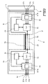
- a vehicle lighting system 6 of the trailer A comprises close to the front side wall 4 of the trailer A, a central light control unit 8, on the other, d. H. rear end of the trailer A, a lighting control unit 10 and these two control units 8, 10 connecting data BUS system 12th
- a left and a right light control unit 10 which controls one of two taillight units 14 each.
- Each tail lamp unit 14 usually performs the light functions of one Stop lamp 14.1, a respective turn signal lamp 14.2, the rear light 14.3 and possibly a reversing light, a rear fog lamp or license plate lights off.
- Stop lamp 14.1 a respective turn signal lamp 14.2
- the rear light 14.3 a respective turn signal lamp 14.2
- possibly a reversing light a rear fog lamp or license plate lights off.
- only one of the usually two existing light control units 10 and rear light units 14 is shown.
- the individual taillights 14.1, 14.2, 14.3 can be equipped with light-emitting diodes (LED) and corresponding ballast resistors for the light-emitting diodes instead of conventional light bulbs.
- LEDs are then connected in the manner of a matrix consisting of parallel LED rows, which in turn consist of several LEDs.
- the central light control unit 8 of the vehicle trailer A accommodates a first processor (CPU) 16, a first changeover switch 18 connected thereto, a first fault detection unit 20 electrically connected to both the processor 16 and the changeover switch 18, and a BUS connection not shown in the drawings ,
- the central light control unit 8 can be signal-technically linked via other signal lines with other control components of the vehicle electrics, z. B. with an electronic brake control device for the brakes of the vehicle trailer.
- Each luminaire control unit 10 accommodates a second processor (CPU) 22, a second changeover switch 24 connected upstream therefrom, and a second fault detection unit 26 electrically connected to both the processor 22 and the changeover switch 24.
- CPU central processing unit
- second changeover switch 24 connected upstream therefrom
- second fault detection unit 26 electrically connected to both the processor 22 and the changeover switch 24.
- the central light control unit 8 is connected via one or more as a bidirectional data bus working data bus lines 28, 35 with positive potential, and a negative potential having ground conductor in electrical connection with the tail lamp units 14.
- a ground potential can also be made of metal serve existing vehicle chassis.
- the BUS lines 28, 35 operate with DC voltage, preferably the DC voltage of the 24-volt electrical system of the towing vehicle, the DC voltage for the transmission of information in addition BUS signals are modulated.
- the processors 16, 22 include BUS connections for modulating or reading the BUS signals.
- the contacting of the bus lines 28, 35 is preferably carried out by appropriate contacts.
- the turn signal is operated right, the corresponding, via the cable connection 2.1, 2.2, 2.3 guided circuit is closed, and this is detected by a signal evaluation of the central light control unit 8.
- the light control unit 8 then initiates via the data bus system 12 a DC modulated signal for switching on the LED of the flashing light of the respective tail lamp unit 14.
- the second processor 22 receives the signal and switches the LEDs of the flashing light individually or in groups depending on integrated switching elements Execution on or off.
- the vehicle lighting system is designed such that in the event of a defect in the processors 16, 22 and / or the data bus system 12, the signals coming from the driver are guided along an evasion circuit. This makes it possible to bypass or bypass the area affected by the defect. This can be done by means of the first and second switch 18, 24, which are the processors 16, 22 upstream or downstream. In the event of a defect, the error detection units 20, 26 detect the error, and they cause via the switches 18, 24, a switching of the signal guide to the avoidance circuit.
- the error detection unit 20, 26 is designed to detect even defects of the processor 16, 22 directly connected with it. Defects on the other processor 22, 16 and on the data bus system, on the other hand, are detected by the error detection unit 20, 26 indirectly via this processor 16, 22, which is directly connected to them.
- emergency signal controllers 32, 34 in the changeover switches 18, 24 take over the backup circuit via parallel to the data bus system between the control units 8, 10 running the distribution of the signals on the available lines 30 and on the corresponding taillights.
- the lines 30 may be dead electrical lines, which are therefore only available on stock and otherwise have no object in the context of the vehicle electrical system. Or the lines 30 may have another function in the context of the vehicle electrical system, and are used in addition for the avoidance circuit if necessary.
- FIG. 2 An alternative embodiment of the avoidance circuit according to the invention shows Fig. 2 , This corresponds largely to the in Fig. 1 1, except that the signals are routed through at least one BUS line 35 of the data bus system 12, rather than via normal electrical cables 30.
- the signal curve in emergency mode is thus guided back to the usual waveform during normal operation in this evasive circuit.
- a priority controller 32 of the first switcher 18 includes an encoder 36 for encoding signals suitably for transmission in at least one operational BUS line 35.
- a priority controller 34 of the second switcher 24 accordingly includes a decoder 38.
Landscapes
- Engineering & Computer Science (AREA)
- Mechanical Engineering (AREA)
- Lighting Device Outwards From Vehicle And Optical Signal (AREA)
Applications Claiming Priority (1)
| Application Number | Priority Date | Filing Date | Title |
|---|---|---|---|
| DE102010044800A DE102010044800A1 (de) | 2010-09-09 | 2010-09-09 | Fahrzeugbeleuchtungssystem mit einer Ausweichschaltung |
Publications (2)
| Publication Number | Publication Date |
|---|---|
| EP2428400A2 true EP2428400A2 (fr) | 2012-03-14 |
| EP2428400A3 EP2428400A3 (fr) | 2014-04-23 |
Family
ID=44677664
Family Applications (1)
| Application Number | Title | Priority Date | Filing Date |
|---|---|---|---|
| EP11180567.7A Withdrawn EP2428400A3 (fr) | 2010-09-09 | 2011-09-08 | Système d'éclairage de véhicule doté d'un circuit de secours |
Country Status (2)
| Country | Link |
|---|---|
| EP (1) | EP2428400A3 (fr) |
| DE (1) | DE102010044800A1 (fr) |
Cited By (1)
| Publication number | Priority date | Publication date | Assignee | Title |
|---|---|---|---|---|
| CN111301283A (zh) * | 2020-03-25 | 2020-06-19 | 北京汽车股份有限公司 | 车辆的车灯控制方法、装置、系统及车辆 |
Families Citing this family (1)
| Publication number | Priority date | Publication date | Assignee | Title |
|---|---|---|---|---|
| DE102023123805A1 (de) * | 2023-09-05 | 2025-03-06 | HELLA GmbH & Co. KGaA | Elektronische Baugruppe eines Anhängers oder für einen Anhänger, Anhänger umfassend eine solche elektronische Baugruppe sowie Verfahren zum Betreiben einer solchen Baugruppe |
Citations (1)
| Publication number | Priority date | Publication date | Assignee | Title |
|---|---|---|---|---|
| DE102009044056A1 (de) | 2009-09-18 | 2011-03-24 | Bpw Bergische Achsen Kg | Fahrzeugbeleuchtungssystem mit einer Lichtsteuereinheit |
Family Cites Families (11)
| Publication number | Priority date | Publication date | Assignee | Title |
|---|---|---|---|---|
| JPS6229247A (ja) * | 1985-07-29 | 1987-02-07 | Nippon Soken Inc | 車両用ロ−カル・エリア・ネツトワ−ク |
| DE19610871C1 (de) * | 1996-03-20 | 1997-06-19 | Daimler Benz Ag | Steuerungsvorrichtung, insbesondere zur Fahrzeugbremslichtsteuerung |
| DE19714849A1 (de) * | 1997-04-10 | 1998-10-15 | Reitter & Schefenacker Gmbh | Leuchte, vorzugsweise Heckleuchte, eines Fahrzeuges, vorzugsweise eines Kraftfahrzeuges |
| DE19919729A1 (de) * | 1999-04-30 | 2000-11-02 | Opel Adam Ag | Vorrichtung zur Ansteuerung einer Funktionsgruppe in einem Kraftfahrzeug |
| DE10127056A1 (de) * | 2001-06-02 | 2002-12-05 | Bosch Gmbh Robert | Vorrichtung zur sicheren Signalerzeugung |
| DE10154983A1 (de) * | 2001-11-08 | 2003-05-22 | Opel Adam Ag | Blinkanlage für ein Kraftfahrzeug |
| DE10261740A1 (de) * | 2002-12-30 | 2004-07-08 | Robert Bosch Gmbh | Ansteuervorrichtung zur Ansteuerung von insbesondere sicherheitsrelevanten Kraftfahrzeug-Komponenten |
| DE10355046B4 (de) * | 2003-11-25 | 2006-02-23 | Lear Corporation Gmbh & Co. Kg | Steuereinrichtung für Außenlichteinheiten von Fahrzeugen, insbesondere Kraftfahrzeugen |
| DE102005055009A1 (de) * | 2005-11-18 | 2007-05-31 | Daimlerchrysler Ag | Vorrichtung zum Steuern eines Beleuchtungssystems in einem Fahrzeug |
| DE102008009905A1 (de) * | 2008-02-19 | 2009-08-20 | Robert Bosch Gmbh | Verfahren zum Bereitstellen einer Notlauffunktion |
| DE102008031771A1 (de) * | 2008-07-04 | 2010-01-14 | Continental Automotive Gmbh | Elektrischer Schaltkreis eines Kraftfahrzeuges |
-
2010
- 2010-09-09 DE DE102010044800A patent/DE102010044800A1/de not_active Withdrawn
-
2011
- 2011-09-08 EP EP11180567.7A patent/EP2428400A3/fr not_active Withdrawn
Patent Citations (1)
| Publication number | Priority date | Publication date | Assignee | Title |
|---|---|---|---|---|
| DE102009044056A1 (de) | 2009-09-18 | 2011-03-24 | Bpw Bergische Achsen Kg | Fahrzeugbeleuchtungssystem mit einer Lichtsteuereinheit |
Cited By (1)
| Publication number | Priority date | Publication date | Assignee | Title |
|---|---|---|---|---|
| CN111301283A (zh) * | 2020-03-25 | 2020-06-19 | 北京汽车股份有限公司 | 车辆的车灯控制方法、装置、系统及车辆 |
Also Published As
| Publication number | Publication date |
|---|---|
| DE102010044800A1 (de) | 2012-03-15 |
| EP2428400A3 (fr) | 2014-04-23 |
Similar Documents
| Publication | Publication Date | Title |
|---|---|---|
| DE102018200334A1 (de) | Fahrtrichtungsanzeiger, insbesondere mit Wischeffekt und Warnblinkfunktion | |
| DE102004045435A1 (de) | Überwachung der Funktion von Glühlampen oder LED-Leuchten in Kraftfahrzeugen | |
| DE4424471C2 (de) | Elektrisches Anhängeranschlußgerät für ein Zugfahrzeug | |
| EP2287043B1 (fr) | Système d'éclairage de véhicule doté d'une détection et d'un affichage de panne d'une lampe de véhicule à DEL | |
| DE3819639C2 (fr) | ||
| DE102009044055A1 (de) | Elektrische Anschlusseinheit für ein Anhängerfahrzeug | |
| DE102009027326A1 (de) | Schaltungsanordnung zum Detektieren eines Ausfalls eines elektrischen Verbrauchers | |
| EP0968880B1 (fr) | Dispositif pour alimenter en courant et tension les éléments des freins d'une remorque de véhicule | |
| EP1653782B1 (fr) | Dispositif de contrôle de LEDs pour feux de véhicule | |
| WO2024149509A1 (fr) | Système d'éclairage d'un véhicule et procédé de commande d'un tel système | |
| EP2428400A2 (fr) | Système d'éclairage de véhicule doté d'un circuit de secours | |
| EP2333919A2 (fr) | Agencement de câble électrique | |
| EP2181869A2 (fr) | Agencement de commande pour une remorque, remorque et adaptateur | |
| DE102015213291A1 (de) | Verfahren zum Betreiben einer ersten und einer zweiten Leuchteinheit eines Kraftfahrzeugs und Schaltungsanordnung | |
| DE202011100493U1 (de) | Schaltungsanordnung in einem Zugfahrzeug sowie einem Anhänger | |
| DE102009044056A1 (de) | Fahrzeugbeleuchtungssystem mit einer Lichtsteuereinheit | |
| DE102012102638A1 (de) | Fahrzeugbeleuchtungssysteme mit Detektierung einer Störung in einer der Fahrzeugleuchten | |
| DE4041459A1 (de) | Einrichtung zum automatischen betaetigen einer last in ersatz einer ausgefallenen anderen last | |
| EP2384935B1 (fr) | Procédé de commutation d'un éclairage de véhicule | |
| DE10063802C2 (de) | Einrichtung zum Erkennen eines an einem Zugfahrzeug angekuppelten Anhängers | |
| DE3149115A1 (de) | Pruefgeraet fuer das elektrische beleuchtungs- und bremssystem von kraftfahrzeugen mit und ohne anhaenger | |
| EP3162634A1 (fr) | Appareil de commande pour le contrôle ou la régulation d'au moins un dispositif d'éclairage et véhicule doté d'un tel appareil | |
| DE102013113007A1 (de) | Steuereinrichtung für Außenlichteinheiten von Fahrzeugen | |
| EP1018453A2 (fr) | Dispositif de securité pour véhicule avec remorque | |
| DE202010016339U1 (de) | Schaltungsanordnung |
Legal Events
| Date | Code | Title | Description |
|---|---|---|---|
| AK | Designated contracting states |
Kind code of ref document: A2 Designated state(s): AL AT BE BG CH CY CZ DE DK EE ES FI FR GB GR HR HU IE IS IT LI LT LU LV MC MK MT NL NO PL PT RO RS SE SI SK SM TR |
|
| AX | Request for extension of the european patent |
Extension state: BA ME |
|
| PUAI | Public reference made under article 153(3) epc to a published international application that has entered the european phase |
Free format text: ORIGINAL CODE: 0009012 |
|
| PUAL | Search report despatched |
Free format text: ORIGINAL CODE: 0009013 |
|
| AK | Designated contracting states |
Kind code of ref document: A3 Designated state(s): AL AT BE BG CH CY CZ DE DK EE ES FI FR GB GR HR HU IE IS IT LI LT LU LV MC MK MT NL NO PL PT RO RS SE SI SK SM TR |
|
| AX | Request for extension of the european patent |
Extension state: BA ME |
|
| RIC1 | Information provided on ipc code assigned before grant |
Ipc: B60Q 11/00 20060101ALI20140314BHEP Ipc: B60Q 1/30 20060101AFI20140314BHEP Ipc: B60R 16/03 20060101ALI20140314BHEP |
|
| 17P | Request for examination filed |
Effective date: 20141017 |
|
| RBV | Designated contracting states (corrected) |
Designated state(s): AL AT BE BG CH CY CZ DE DK EE ES FI FR GB GR HR HU IE IS IT LI LT LU LV MC MK MT NL NO PL PT RO RS SE SI SK SM TR |
|
| 17Q | First examination report despatched |
Effective date: 20150127 |
|
| STAA | Information on the status of an ep patent application or granted ep patent |
Free format text: STATUS: THE APPLICATION IS DEEMED TO BE WITHDRAWN |
|
| 18D | Application deemed to be withdrawn |
Effective date: 20150807 |