EP2333948A2 - Dispositif de contrôle d'onduleur et système d'entraînement de moteur - Google Patents
Dispositif de contrôle d'onduleur et système d'entraînement de moteur Download PDFInfo
- Publication number
- EP2333948A2 EP2333948A2 EP10015391A EP10015391A EP2333948A2 EP 2333948 A2 EP2333948 A2 EP 2333948A2 EP 10015391 A EP10015391 A EP 10015391A EP 10015391 A EP10015391 A EP 10015391A EP 2333948 A2 EP2333948 A2 EP 2333948A2
- Authority
- EP
- European Patent Office
- Prior art keywords
- phase
- current
- voltage
- axis
- control device
- Prior art date
- Legal status (The legal status is an assumption and is not a legal conclusion. Google has not performed a legal analysis and makes no representation as to the accuracy of the status listed.)
- Withdrawn
Links
Images








Classifications
-
- H—ELECTRICITY
- H02—GENERATION; CONVERSION OR DISTRIBUTION OF ELECTRIC POWER
- H02P—CONTROL OR REGULATION OF ELECTRIC MOTORS, ELECTRIC GENERATORS OR DYNAMO-ELECTRIC CONVERTERS; CONTROLLING TRANSFORMERS, REACTORS OR CHOKE COILS
- H02P27/00—Arrangements or methods for the control of AC motors characterised by the kind of supply voltage
- H02P27/04—Arrangements or methods for the control of AC motors characterised by the kind of supply voltage using variable-frequency supply voltage, e.g. inverter or converter supply voltage
- H02P27/06—Arrangements or methods for the control of AC motors characterised by the kind of supply voltage using variable-frequency supply voltage, e.g. inverter or converter supply voltage using DC to AC converters or inverters
- H02P27/08—Arrangements or methods for the control of AC motors characterised by the kind of supply voltage using variable-frequency supply voltage, e.g. inverter or converter supply voltage using DC to AC converters or inverters with pulse width modulation
-
- H—ELECTRICITY
- H02—GENERATION; CONVERSION OR DISTRIBUTION OF ELECTRIC POWER
- H02P—CONTROL OR REGULATION OF ELECTRIC MOTORS, ELECTRIC GENERATORS OR DYNAMO-ELECTRIC CONVERTERS; CONTROLLING TRANSFORMERS, REACTORS OR CHOKE COILS
- H02P21/00—Arrangements or methods for the control of electric machines by vector control, e.g. by control of field orientation
- H02P21/22—Current control, e.g. using a current control loop
-
- G—PHYSICS
- G01—MEASURING; TESTING
- G01R—MEASURING ELECTRIC VARIABLES; MEASURING MAGNETIC VARIABLES
- G01R19/00—Arrangements for measuring currents or voltages or for indicating presence or sign thereof
- G01R19/0092—Measuring current only
-
- H—ELECTRICITY
- H02—GENERATION; CONVERSION OR DISTRIBUTION OF ELECTRIC POWER
- H02M—APPARATUS FOR CONVERSION BETWEEN AC AND AC, BETWEEN AC AND DC, OR BETWEEN DC AND DC, AND FOR USE WITH MAINS OR SIMILAR POWER SUPPLY SYSTEMS; CONVERSION OF DC OR AC INPUT POWER INTO SURGE OUTPUT POWER; CONTROL OR REGULATION THEREOF
- H02M1/00—Details of apparatus for conversion
- H02M1/0003—Details of control, feedback or regulation circuits
- H02M1/0009—Devices or circuits for detecting current in a converter
-
- H—ELECTRICITY
- H02—GENERATION; CONVERSION OR DISTRIBUTION OF ELECTRIC POWER
- H02M—APPARATUS FOR CONVERSION BETWEEN AC AND AC, BETWEEN AC AND DC, OR BETWEEN DC AND DC, AND FOR USE WITH MAINS OR SIMILAR POWER SUPPLY SYSTEMS; CONVERSION OF DC OR AC INPUT POWER INTO SURGE OUTPUT POWER; CONTROL OR REGULATION THEREOF
- H02M7/00—Conversion of AC power input into DC power output; Conversion of DC power input into AC power output
- H02M7/42—Conversion of DC power input into AC power output without possibility of reversal
- H02M7/44—Conversion of DC power input into AC power output without possibility of reversal by static converters
- H02M7/48—Conversion of DC power input into AC power output without possibility of reversal by static converters using discharge tubes with control electrode or semiconductor devices with control electrode
- H02M7/53—Conversion of DC power input into AC power output without possibility of reversal by static converters using discharge tubes with control electrode or semiconductor devices with control electrode using devices of a triode or transistor type requiring continuous application of a control signal
- H02M7/537—Conversion of DC power input into AC power output without possibility of reversal by static converters using discharge tubes with control electrode or semiconductor devices with control electrode using devices of a triode or transistor type requiring continuous application of a control signal using semiconductor devices only, e.g. single switched pulse inverters
- H02M7/5387—Conversion of DC power input into AC power output without possibility of reversal by static converters using discharge tubes with control electrode or semiconductor devices with control electrode using devices of a triode or transistor type requiring continuous application of a control signal using semiconductor devices only, e.g. single switched pulse inverters in a bridge configuration
- H02M7/53871—Conversion of DC power input into AC power output without possibility of reversal by static converters using discharge tubes with control electrode or semiconductor devices with control electrode using devices of a triode or transistor type requiring continuous application of a control signal using semiconductor devices only, e.g. single switched pulse inverters in a bridge configuration with automatic control of output voltage or current
- H02M7/53875—Conversion of DC power input into AC power output without possibility of reversal by static converters using discharge tubes with control electrode or semiconductor devices with control electrode using devices of a triode or transistor type requiring continuous application of a control signal using semiconductor devices only, e.g. single switched pulse inverters in a bridge configuration with automatic control of output voltage or current with analogue control of three-phase output
- H02M7/53876—Conversion of DC power input into AC power output without possibility of reversal by static converters using discharge tubes with control electrode or semiconductor devices with control electrode using devices of a triode or transistor type requiring continuous application of a control signal using semiconductor devices only, e.g. single switched pulse inverters in a bridge configuration with automatic control of output voltage or current with analogue control of three-phase output based on synthesising a desired voltage vector via the selection of appropriate fundamental voltage vectors, and corresponding dwelling times
-
- H—ELECTRICITY
- H02—GENERATION; CONVERSION OR DISTRIBUTION OF ELECTRIC POWER
- H02M—APPARATUS FOR CONVERSION BETWEEN AC AND AC, BETWEEN AC AND DC, OR BETWEEN DC AND DC, AND FOR USE WITH MAINS OR SIMILAR POWER SUPPLY SYSTEMS; CONVERSION OF DC OR AC INPUT POWER INTO SURGE OUTPUT POWER; CONTROL OR REGULATION THEREOF
- H02M7/00—Conversion of AC power input into DC power output; Conversion of DC power input into AC power output
- H02M7/42—Conversion of DC power input into AC power output without possibility of reversal
- H02M7/44—Conversion of DC power input into AC power output without possibility of reversal by static converters
- H02M7/48—Conversion of DC power input into AC power output without possibility of reversal by static converters using discharge tubes with control electrode or semiconductor devices with control electrode
- H02M7/53—Conversion of DC power input into AC power output without possibility of reversal by static converters using discharge tubes with control electrode or semiconductor devices with control electrode using devices of a triode or transistor type requiring continuous application of a control signal
- H02M7/537—Conversion of DC power input into AC power output without possibility of reversal by static converters using discharge tubes with control electrode or semiconductor devices with control electrode using devices of a triode or transistor type requiring continuous application of a control signal using semiconductor devices only, e.g. single switched pulse inverters
- H02M7/539—Conversion of DC power input into AC power output without possibility of reversal by static converters using discharge tubes with control electrode or semiconductor devices with control electrode using devices of a triode or transistor type requiring continuous application of a control signal using semiconductor devices only, e.g. single switched pulse inverters with automatic control of output wave form or frequency
- H02M7/5395—Conversion of DC power input into AC power output without possibility of reversal by static converters using discharge tubes with control electrode or semiconductor devices with control electrode using devices of a triode or transistor type requiring continuous application of a control signal using semiconductor devices only, e.g. single switched pulse inverters with automatic control of output wave form or frequency by pulse-width modulation
Definitions
- the present invention relates to an inverter control device which controls an inverter and a motor drive system which utilizes the inverter control device.
- phase currents e.g., U-phase current and V-phase current
- U-phase current and V-phase current are usually used for detecting two phase currents, but the use of two current sensors causes cost increase of the entire system in which the motor is incorporated.
- FIG. 21 illustrates a general block diagram of a conventional motor drive system in which the single shunt current detection method is adopted.
- An inverter (PWM inverter) 902 is equipped with half bridge circuits for three phases, each of which includes an upper arm and a lower arm.
- the inverter 902 switches the individual arms in accordance with specified three-phase voltage values supplied from a motor control device 903, so as to convert a DC voltage from a DC power supply 904 into three-phase AC voltages.
- the three-phase AC voltages are supplied to a three-phase permanent-magnet synchronous motor 901, so that the motor 901 is driven and controlled.
- a line connecting the individual lower arms in the inverter 902 with the DC power supply 904 is called a bus line 913.
- a current sensor 905 transmits a signal indicating bus current that flows in the bus line 913 to the motor control device 903.
- the motor control device 903 performs sampling of an output signal of the current sensor 905 at appropriate timing, so as to detect phase current of a maximum voltage phase (at which a voltage level becomes highest) and phase current of a minimum voltage phase (at which a voltage level becomes lowest), namely phase current values of two phases.
- phase currents of two phases can be detected by the above-mentioned process.
- a difference between a pulse width of a PWM signal of the maximum voltage phase and a pulse width of a PWM signal of the intermediate voltage phase decreases so that the phase current detection of the maximum voltage phase becomes difficult.
- a difference between the pulse width of the PWM signal of the intermediate voltage phase and the pulse width of the PWM signal of the minimum voltage phase decreases so that the phase current detection of the minimum voltage phase becomes difficult.
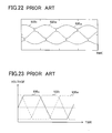
- FIG. 22 A usual correction example of a specified voltage value (pulse width) that also supports the above-mentioned correction is illustrated in FIG. 22 .
- the horizontal axis represents time
- curved lines 920u, 920v, and 920w indicate voltage waveforms of a U-phase, a V-phase, and a W-phase, respectively.
- the specified voltage value (pulse width) of each phase is corrected so that the voltage level of the maximum voltage phase and the voltage level of the intermediate voltage phase, as well as the voltage level of the intermediate voltage phase and the voltage level of the minimum voltage phase do not approach each other closer than a predetermined distance.
- phase currents of two phases can be detected stably.
- each phase voltage is distorted as illustrated in FIG. 22 . Therefore, noise and vibration of the apparatus incorporating the motor drive system are apt to increase. In addition, the usable voltage range is narrowed by the above-mentioned correction.
- the inverter 902 performs a PWM control for driving the motor 901
- the control of supplying a sine wave-like voltage to the armature winding of each phase of the motor 901 in the PWM control is called sine wave PWM control.
- a rectangular wave drive is used instead of the sine wave PWM control.
- a voltage having a voltage waveform similar to a rectangular wave is applied to armature winding of each phase of the motor 901.
- a modulation method or PWM for realizing the rectangular wave drive is generally called overmodulation or overmodulation PWM. In the graph illustrated in FIG.
- the horizontal axis represents time
- a solid line 930u, a broken line 930v and a dot-dashed line 930w respectively indicate voltage waveforms of the U-phase, the V-phase, and the W-phase when the overmodulation PWM is performed.
- a method to estimate three phase currents using specified current values in the case where phase currents of two phases are hardly detected is equipped with a block which estimates three-phase current values I u * , I v * , and I w * on the basis of specified current values I d * and I q * on a dq coordinate axis, and a rotor position (detected phase) ⁇ dc (see coordinate conversion means 5 illustrated in FIG. 1 of JP-A-2009-055693 ).
- This estimation can be performed by the following equations, but there is a large amount of operations by the following equations.
- I u * 2 3 ⁇ I d * ⁇ cos ⁇ dc - I q * ⁇ sin ⁇ dc
- I v * - 1 6 ⁇ I d * ⁇ cos ⁇ dc - I q * ⁇ sin ⁇ dc + 1 2 ⁇ I d * ⁇ sin ⁇ dc + I q * ⁇ cos ⁇ dc
- I w * - 1 6 ⁇ I d * ⁇ cos ⁇ dc - I q * ⁇ sin ⁇ dc - 1 2 ⁇ I d * ⁇ sin ⁇ dc + I q * ⁇ cos ⁇ dc
- An inverter control device includes a phase current detection unit which is connected to a current sensor.
- the current sensor detects current flowing between a three-phase inverter which converts a DC voltage into AC three-phase voltages and a DC power supply which outputs the DC voltage.
- the phase current detection unit detects phase current flowing in each phase of the inverter from a result of detection by the current sensor, so that the inverter control device controls the inverter on the basis of a result of detection by the phase current detection unit.
- the phase current detection unit includes an estimation block which estimates phase current of an intermediate voltage phase or current corresponding to the phase current of the intermediate voltage phase as a first estimated current, and the phase current detection unit estimates phase current of a maximum voltage phase or phase current of a minimum voltage phase using the first estimated current so that each phase current can be detected.
- phase current corresponding to the highest phase voltage among the three-phase voltages is phase current of the maximum voltage phase
- phase current corresponding to the minimum phase voltage is phase current of the minimum voltage phase
- one remaining phase current is phase current of the intermediate voltage phase.
- the inverter control device is a motor control device which controls a three-phase motor via control of the inverter on the basis of the result of detection by the phase current detection unit, and the phase current detected by the phase current detection unit is phase current flowing in three-phase armature windings of the motor.
- phase current of the armature winding to which the highest phase voltage is applied is phase current of the maximum voltage phase
- phase current of the armature winding to which the lowest phase voltage is applied is phase current of the minimum voltage phase
- phase current of one remaining armature winding is phase current of the intermediate voltage phase.
- the inverter control device as the motor control device controls the motor on the basis of specified current values to be targets of currents supplied to the three-phase armature windings, and the phase current detection unit estimates the first estimated current on the basis of the specified current values, or estimates the first estimated current at a second time after a first time on the basis of a detected current value of the supplied current, generated by using a result of detection by the phase current detection unit at the first time.
- the inverter control device as the motor control device controls the motor on the basis of a specified voltage vector to be a target of a combined vector of the phase voltages of three phases
- the inverter control device further includes a specified voltage vector generation unit which generates the specified voltage vector on the basis of the result of detection by the phase current detection unit
- the estimation block estimates the phase current of the intermediate voltage phase as the first estimated current
- the specified current values include a specified current value on an ab coordinate system rotating step by step of 60 degrees in electrical angle in accordance with the phase voltages of three phases or in accordance with a phase of the specified voltage vector with respect to a predetermined fixed axis
- the detected current value includes a detected current value on the ab coordinate system.
- the phase current detection unit is capable of performing a first process of detecting the phase current of the maximum voltage phase and the phase current of the minimum voltage phase from the result of detection by the current sensor so as to detect each phase current, and a second process of detecting one of phase currents of the maximum voltage phase and the minimum voltage phase from the result of detection by the current sensor, and estimating the other phase current using the first estimated current by the estimation block, so as to detect each phase current.
- the phase current detection unit selectively performs the first or the second process on the basis of the phase voltages of three phases.
- the phase current detection unit selectively performs the first or the second process on the basis of a voltage difference between phase voltage of the maximum voltage phase and phase voltage of the intermediate voltage phase, and a voltage difference between phase voltage of the minimum voltage phase and the phase voltage of the intermediate voltage phase.
- a motor drive system includes a three-phase motor, an inverter which drives the three-phase motor, and a motor control device which controls the motor via the inverter.
- the above-mentioned inverter control device is used as the motor control device.
- an inverter control device and a motor drive system that can estimate phase current that is hardly detected from current between the inverter and the DC power supply, with a simple calculation.
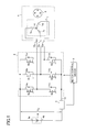
- FIG. 1 is a block diagram of a motor drive system according to the first embodiment of the present invention.
- the motor drive system illustrated in FIG. 1 includes a three-phase permanent-magnet synchronous motor 1 (hereinafter simply referred to as “motor 1 "), a pulse width modulation (PWM) inverter 2 (hereinafter simply referred to as “inverter 2”), a motor control device 3, a DC power supply 4, and a current sensor 5.
- the DC power supply 4 outputs a DC voltage between a positive output terminal 4a and a negative output terminal 4b, where the negative output terminal 4b is a low voltage side.
- the DC voltage output from the DC power supply 4 and a voltage value thereof are denoted by V dc .
- the motor control device 3 controls the inverter 2 so as to control the motor 1. Therefore, the motor control device 3 can also be called as an inverter control device.
- the motor 1 includes a rotor 6 having a permanent magnet, and a stator 7 having armature windings 7u, 7v, and 7w of a U-phase, a V-phase, and a W-phase.
- the armature windings 7u, 7v, and 7w are connected at a neutral point 14 as a center in a form of Y-connection. Non-connection ends of the armature windings 7u, 7v and 7w that are opposite ends to the neutral point 14 are connected to terminals 12u, 12v and 12w, respectively.
- the inverter 2 includes a U-phase half bridge circuit, a V-phase half bridge circuit, and a W-phase half bridge circuit.
- Each of the half bridge circuits includes a pair of switching elements.
- the pair of switching elements are connected in series between the positive output terminal 4a and the negative output terminal 4b of the DC power supply 4, so that each of the half bridge circuits is supplied with a DC voltage V dc from the DC power supply 4.
- the U-phase half bridge circuit is constituted of a switching element 8u on the high voltage side (hereinafter also referred to as an upper arm 8u) and a switching element 9u on the low voltage side (hereinafter also referred to as a lower arm 9u).
- the V-phase half bridge circuit is constituted of a switching element 8v on the high voltage side (hereinafter also referred to as an upper arm 8v) and a switching element 9v on the low voltage side (hereinafter also referred to as a lower arm 9v).
- the W-phase half bridge circuit is constituted of a switching element 8w on the high voltage side (hereinafter also referred to as an upper arm 8w) and a switching element 9w on the low voltage side (hereinafter also referred to as a lower arm 9w).
- the switching elements 8u, 8v, 8w, 9u, 9v, and 9w are respectively connected to diodes 10u, 10v, 10w, 1 1u, 11 v, and 11 w in parallel so that the direction from the low voltage side to the high voltage side of the DC power supply 4 becomes the forward direction.
- Each of the diodes works as a freewheel diode.
- connection node of the upper arm 8u and the lower arm 9u that are connected in series, the connection node of the upper arm 8v and the lower arm 9v that are connected in series, the connection node of the upper arm 8w and the lower arm 9w that are connected in series are connected to the terminals 12u, 12v and 12w, respectively.
- field-effect transistors are illustrated as the switching elements in FIG. 1 , but they can be replaced with insulated gate bipolar transistors (IGBTs) or the like.
- the inverter 2 supplies a control terminal (base or gate) of each switching element in the inverter 2 with a pulse width modulated signal (PWM signal) based on specified three-phase voltage values generated by the motor control device 3, so that each switching element performs switching action.
- the specified three-phase voltage values are constituted of a specified U-phase voltage value v u * , a specified V-phase voltage value v v * , and a specified W-phase voltage value v w * .
- the DC voltage applied to the inverter 2 from the DC power supply 4 is modulated by pulse width modulation (PWM modulation) when the switching elements in the inverter 2 perform switching actions, and is converted into three-phase AC voltages.
- PWM modulation pulse width modulation
- the three-phase AC voltages are applied to the motor 1, currents corresponding to the three-phase AC voltages flow in the armature windings (7u, 7v, and 7w) so that the motor 1 is driven.
- the current sensor 5 detects current (hereinafter referred to as "bus current") flowing in a bus line 13 of the inverter 2.
- the bus current includes a DC component, which can be regarded as DC current.
- the wiring line to which the low voltage sides of the lower arms 9u, 9v, and 9w are connected together is the bus line 13, and the current sensor 5 is inserted in the bus line 13 in series.
- the current sensor 5 transmits a signal indicating a current value of the detected bus current to the motor control device 3.
- the motor control device 3 generates the specified three-phase voltage values on the basis of an output signal of the current sensor 5.
- the current sensor 5 is, for example, a shunt resistor, a current transformer, or the like.
- the motor drive system illustrated in FIG. 1 adopts a so-called single shunt current detection method for detecting three-phase currents from the bus current.
- FIGS. 2A and 2B illustrates an analysis model diagram of the motor 1.
- FIG. 2A illustrates armature winding fixed axes of the U-phase, the V-phase, and the W-phase (hereinafter also referred to as a U-phase axis, a V-phase axis, and a W-phase axis).
- Numeral 6a denotes a permanent magnet attached to the rotor 6 of the motor 1.
- a phase of the V-phase axis leads the U-phase axis by 120 degrees in electrical angle
- a phase of the W-phase axis further leads the V-phase axis by 120 degrees in electrical angle.
- a d-axis is set to the direction of the magnetic flux generated by the permanent magnet 6a, and a q-axis is set to the phase leading the d-axis by 90 degrees in electrical angle.
- a counterclockwise direction corresponds to a phase leading direction.
- the d-axis and the q-axis are collectively referred to as a dq-axis, and a rotation coordinate system in which the d-axis and the q-axis are selected as its coordinate axes is referred to as a dq coordinate system.
- the dq-axis is rotating, and its rotational speed is denoted by ⁇ .
- an angle (phase) of the d-axis viewed from the U-phase axis is denoted by ⁇ .
- the angle denoted by ⁇ is an angle in electrical angle, which is usually called a rotor position or a magnetic pole position, too.
- the rotational speed denoted by ⁇ is an angular speed in electrical angle.
- a state quantity denoted by ⁇ is referred to as a rotor position (or phase), and a state quantity denoted by ⁇ is referred to as a rotational speed.
- the state quantity can also be read as a physical quantity.
- an angle and a phase indicate those in electrical angle unless otherwise noted, and a unit thereof is radian or degree.
- FIG. 2B illustrates a relationship among the U-phase axis, the V-phase axis, and the W-phase axis, and also a ⁇ -axis and a ⁇ -axis that are orthogonal to each other.
- the ⁇ -axis agrees with the U-phase axis, and the ⁇ -axis leads the ⁇ -axis by 90 degrees in electrical angle.
- the U-phase axis, the V-phase axis, the W-phase axis, the ⁇ -axis, and the ⁇ -axis are fixed axes that are fixed to regardless of rotation of the rotor 6.
- the ⁇ -axis and the ⁇ -axis are collectively referred to as an ⁇ -axis, and a fixed coordinate system in which the ⁇ -axis and the ⁇ -axis are selected as its coordinate axes is referred to as an ⁇ coordinate system.
- the three-phase AC voltages applied to the motor 1 from the inverter 2 include a U-phase voltage indicating a voltage applied to a U-phase armature winding 7u, a V-phase voltage indicating a voltage applied to a V-phase armature winding 7v, and a W-phase voltage indicating a voltage applied to a W-phase armature winding 7w.
- the U-phase voltage, the V-phase voltage, and the W-phase voltage are voltages at terminals 12u, 12v, and 12w, respectively, viewed from a neutral point 14.
- the U-phase voltage, the V-phase voltage, and the W-phase voltage are denoted by v u , v v , and v w , respectively.
- the U-phase voltage, the V-phase voltage, and the W-phase voltage are collectively referred to as a phase voltage, or each of them is referred to as the same.
- a general voltage applied to the motor 1, which is a combined voltage of the U-phase voltage, the V-phase voltage, and the W-phase voltage, is referred to as a motor voltage (motor terminal voltage) and is denoted by V a .
- the motor control device 3 controls the inverter 2, so that the U-phase voltage v u , the V-phase voltage Vv, and the W-phase voltage Vw have voltage values in accordance with the U-phase, V-phase, and W-phase specified voltage values v u * , v v * , and v w * , respectively.
- the U-phase component, the V-phase component, and the W-phase component of the current supplied from the inverter 2 to the motor 1 when the motor voltage V a is applied namely, currents flowing in the U-phase, V-phase, and W-phase armature windings 7u, 7v, and 7w are referred to as a U-phase current, a V-phase current, and a W-phase current.
- Each of the U-phase current, the V-phase current, and the W-phase current is also referred to as a phase current, or they are collectively referred to as the same.
- phase current a polarity of current in the direction flowing from the terminal 12u, 12v, or 12w to the neutral point 14 is regarded as positive, and a polarity of current in the direction flowing out from the neutral point 14 is regarded as negative.
- the U-phase current, the V-phase current, and the W-phase current are denoted by i u , ivy, and i w , respectively.
- a general current supplied to the motor 1, which is a combined current of the U-phase, V-phase, and W-phase currents is referred to as a motor current (armature current) and is denoted by I a .
- a phase in which the corresponding phase voltage is highest is referred to as a “maximum phase” or a “maximum voltage phase”
- a phase in which the corresponding phase voltage is lowest is referred to as a “minimum phase” or a “minimum voltage phase”.
- a phase in which the corresponding phase voltage is not highest or lowest is referred to as an "intermediate phase” or an “intermediate voltage phase”.
- the U-phase is the maximum phase
- the V-phase is the intermediate phase
- the W-phase is the minimum phase.
- v v >v w >v u is satisfied
- the V-phase is the maximum phase
- the W-phase is the intermediate phase
- the U-phase is the minimum phase.
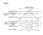
- the carrier signal CS having a value that changes periodically like a triangular wave is compared with voltage levels of the maximum phase, the intermediate phase, and the minimum phase defined by the specified three-phase voltage values, so that PWM signals corresponding to the maximum phase, the intermediate phase, and the minimum phase are generated.
- FIG. 3 illustrates an example of the PWM signals in the case where the three-phase modulation is used.
- the PWM signal of a noted phase is high level, the upper arm of the noted phase is turned on.
- the PWM signal of a noted phase is low level, the upper arm of the noted phase is turned off.
- the U-phase, the V-phase, and the W-phase correspond to the maximum phase, the intermediate phase, and the minimum phase, respectively.
- v u * >v v * >v w * is satisfied.
- a value CS VAL of the carrier signal CS is compared with v u * , v v * , and v w * .
- the carrier period is a period of the carrier signal CS. In one carrier period, CS VAL increases from zero to a predetermined peak value, and then decreases to zero.
- the phase current of the minimum phase can be detected by detecting the bus current.
- the phase current of the maximum phase can be detected by detecting the bus current.
- a d-axis component, a q-axis component, an ⁇ -axis component, and a ⁇ -axis component of the motor voltage V a are referred to as a d-axis voltage, a q-axis voltage, an ⁇ -axis voltage, and a ⁇ -axis voltage, and are denoted by v d , v q , v ⁇ , and v ⁇ , respectively.
- a d-axis component, a q-axis component, an ⁇ -axis component, and a ⁇ -axis component of the motor current I a are referred to as a d-axis current, a q-axis current, an ⁇ -axis current, and a ⁇ -axis current, and are denoted by i d , iq, i ⁇ , and i ⁇ , respectively.
- v d is also used as a symbol denoting a value of the d-axis voltage.
- state quantities other than v d including state quantities concerning voltage or current.
- only a symbol (such as i d ) may be used for expressing a state quantity or a specified value corresponding to the symbol.
- d-axis current i d may be expressed simply by "current i d " or "i d "
- d-axis current value i d may be expressed simply by "current value i d " or "i d ".
- a numeral may be added for omitting or abbreviating a name of a portion corresponding to the numeral.
- a current detection block 42 illustrated in FIG. 8 that will be described later may be referred to as a block 42.
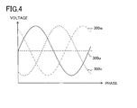
- FIG. 4 illustrates a typical waveform example of the three-phase AC voltages applied to the motor 1.
- the three-phase AC voltages illustrated in FIG. 4 are three-phase AC voltages applied to the motor 1 when the three-phase modulation is performed by the inverter 2.
- the solid line 300u, the broken line 300v and the dot-dashed line 300w respectively indicate waveforms of the U-phase, V-phase, and W-phase voltages when the three-phase modulation is performed
- the horizontal axis of the graph illustrated in FIG. 4 represents the phase ⁇ .
- Each of the voltage waveforms 300u, 300v, and 300w is a sine wave with respect to a medium potential between the positive output terminal 4a and the negative output terminal 4b, and an amplitude of the sine wave is (1 ⁇ 2) .
- V dc or smaller.
- the maximum value of the amplitude of the sine wave-like voltage is (1 ⁇ 2) .
- V dc the maximum value of the amplitude of the sine wave-like voltage.
- FIG. 5 is a space vector diagram illustrating a relationship among the U-phase axis, the V-phase axis, and the W-phase axis that are fixed axes, and the d-axis and the q-axis that are rotating axes, and a specified voltage vector.
- the vector denoted by 320 is the specified voltage vector.
- a phase of the specified voltage vector 320 viewed from the q-axis in the counterclockwise direction (i.e., a lead angle of the specified voltage vector 320 from the q-axis) is denoted by ⁇ .
- the phase of the specified voltage vector 320 from the U-phase axis is expressed by ( ⁇ + ⁇ + ⁇ /2).
- a value specifying a voltage to be applied to the motor 1 is generated.
- the specified voltage vector 320 is obtained by vector expression of the value.
- the specified d-axis voltage value v d * and the specified q-axis voltage value v q * are calculated in the motor control device 3, for example, and the specified voltage vector 320 is expressed by V d * and v q * .
- the ⁇ -axis specified voltage value v ⁇ * and the ⁇ -axis specified voltage value v ⁇ * are calculated in the motor control device 3, for example, and the specified voltage vector 320 is expressed by v ⁇ * and v ⁇ * .
- the d-axis component, the q-axis component, the ⁇ -axis component, and the ⁇ -axis component of the specified voltage vector 320 are V d * , v q * , v ⁇ * , and v ⁇ * , respectively.
- an output signal of the current sensor 5 i.e., a bus current value
- a phase current value of the intermediate phase can be calculated by operation because a sum of the U, V, and W phase currents is zero.
- a difference of pulse width of the PWM signal between the maximum phase and the intermediate phase is decreased.
- the asterisk region 321 with hatching that includes a vicinity of the U-phase axis, a vicinity of the V-phase axis, and a vicinity of the W-phase axis indicates the region where phase currents of two phases cannot be detected.
- the specified voltage vector 320 is located at a vicinity of the U-phase axis.
- the specified voltage vector 320 is located at a vicinity of the V-phase axis. In this way, the region 321 where phase currents of two phases cannot be detected exists every 60 degrees in electrical angle from the U-phase axis.
- an a n -axis and a b n -axis are defined as illustrated in FIGS. 6A and 6B .
- n denotes an integer
- n is also referred to as a voltage state value.
- the a n -axis is an axis obtained by rotating the ⁇ -axis by n ⁇ /3 (i.e., n times 60 degrees) in the phase leading direction
- the b n -axis is an axis obtained by rotating the ⁇ -axis by n . ⁇ /3 (i.e., n times 60 degrees) in the phase leading direction.
- FIG. 6A illustrates a 0 -, a 1 -, a 2 -, a 3 -, a 4 -, and a 5 -axes as the a n -axis.
- the a 0 -axis and the a 6 -axis are the same axis.
- b 0 -, b 1- , b 2 -, b 3 -, b 4 -, and b 5 -axes are axes having phases leading by 90 degrees from the a 0 -, a 1 -, a 2 -, a 3 -, a 4 -, and a 5 -axes, respectively.
- the b 0 -axis and the b 6 -axis are the same axis.
- the motor control device 3 sets an a-axis and a b-axis as follows;
- the a n -axis and the b n -axis are collectively referred to as an a n b n -axis, and a coordinate system in which the a n -axis and the b n -axis are selected as its coordinate axes is referred to as an a n b n coordinate system.
- the ⁇ -axis and the b-axis are collectively referred to as an ab-axis, and a coordinate system in which the ⁇ -axis and the b-axis are selected as its coordinate axes is referred to as an ab coordinate system.
- the ab coordinate system is a coordinate system obtained by rotating the ⁇ coordinate system by n times 60 degrees in the phase leading direction.
- ⁇ indicates a threshold value at a boundary for distinguishing whether or not phase currents of two phases can be detect by the single shunt current detection method.
- FIG. 7 is a block diagram of the motor drive system illustrated in FIG. 1 , which includes an internal block portion of the motor control device 3.
- the motor control device 3 is equipped with a phase current detection unit 20, a coordinate converter 21, a speed controller 22, a current controller 23, a coordinate converter 24, a position detector 31, and a differential unit 32.
- the speed controller 22 can also be referred to as a specified current value generation unit.
- the current controller 23 can also be referred to as a specified voltage value generation unit or a specified voltage vector generation unit.
- a position sensor 30 is a component of the motor drive system. It is possible to consider that the position sensor 30 is included in components of the motor control device 3, or it is possible to consider that the position sensor 30 is not included in components of the motor control device 3. Further, it is possible to consider that the motor control device 3 also includes the current sensor 5.
- Each portion of the motor drive system illustrated in FIG. 7 updates state quantities (such as i d , i q , ⁇ , and ⁇ ) or specified values (such as v d * and v q * ) that are calculated (or detected) and output by itself at a predetermined control period, so as to perform necessary operation using latest values that can be obtained at the time point.
- state quantities such as i d , i q , ⁇ , and ⁇
- specified values such as v d * and v q *
- the position sensor 30 is a rotary encoder or the like, which transmits to the position detector 31 a signal corresponding to a rotor position ⁇ of the rotor 6 of the motor 1.
- the position detector 31 detects a rotor position ⁇ on the basis of an output signal of the position sensor 30.
- the differential unit 32 differentiates the rotor position ⁇ so as to calculate the rotational speed ⁇ and outputs the result.
- the current sensor 5 detects the bus current and outputs a signal indicating a current value of the bus current.
- the bus current is denoted by i dc .
- the output signal of the current sensor 5 is sent to the phase current detection unit 21.
- the phase current detection unit 21 is supplied with the bus current i dc , the specified three-phase voltage values v u * , v v * , and V w * from the coordinate converter 24, the d-axis specified current value i d * and the specified q-axis current value i q * from the speed controller 22, and the rotor position ⁇ from the position detector 31.
- the phase current detection unit 21 calculates current values i u , i v , and i w of each phase current on the basis of the supplied values and outputs the result (detailed calculation method will be described later).
- the coordinate converter 21 converts the current values i u , i v , and i w from the phase current detection unit 20 into current values on the dq-axis on the basis of the rotor position ⁇ from the position detector 31, so as to calculate the d-axis current value i d and the q-axis current value i q .
- the speed controller 22 is supplied with a specified rotation speed value ⁇ * externally and the rotational speed ⁇ from the differential unit 32.
- the specified rotation speed value ⁇ * is a specified value for controlling the motor 1 (rotor 6) to rotate at a desired speed, which works as a target value of the rotational speed ⁇ .
- the speed controller 22 calculates and outputs the specified q-axis current value i q * on the basis of a speed error ( ⁇ * - ⁇ ). For instance, i q * is calculated so that ( ⁇ * - ⁇ ) is converged to zero by proportional plus integral control.
- the speed controller 22 calculates and outputs the specified d-axis current value i d * while referring to i q * as necessary.
- i d * for realizing maximum torque control or i d * for realizing flux-weakening control is calculated.
- i d * works as a target value of the d-axis current i d to be followed by the d-axis current value i d
- i q * works as a target value of the q-axis current i q to be followed by the q-axis current value i q .
- the current controller 23 is supplied with specified values i d * and i q * from the speed controller 22 and is supplied with current values i d and i q from the coordinate converter 21.
- the current controller 23 performs proportional plus integral control so that current errors (i d * -i d ) and (i q * -i q ) are converged to zero, thereby it calculates and outputs the specified d-axis voltage value v d * and the specified q-axis voltage value v q * .
- v d * works as a target value of the d-axis voltage v d to be followed by the d-axis voltage v d
- v q * works as a target value of the q-axis voltage v q to be followed by the q-axis voltage value v q .
- the coordinate converter 24 converts the specified values v d * and v q * from the current controller 23 into specified values on the U, V, and W phase axes on the basis of the rotor position ⁇ from the position detector 31. In other words, the coordinate converter 24 converts the specified values v d * and v q * into the specified three-phase voltage values v u * , v v * , and v w * on the basis of the rotor position ⁇ .
- a PWM signal generator (not shown) disposed in the inverter 2 or a PWM signal generator (not shown) disposed between the coordinate converter 24 and the inverter 2 generates a PWM signal for each switching element (arm) in the inverter 2 on the basis of the specified three-phase voltage values v u * , v v * , and v w * from the coordinate converter 24, so that the U-phase, V-phase, and W-phase voltage values v u , v v , and v w become voltage values according to v u * , v v * , and v w * , respectively.
- the inverter 2 controls switching of each switching element in the inverter 2 in accordance with the PWM signal, so as to apply to the motor 1 the U-phase, V-phase, and W-phase voltages according to the specified three-phase voltage values v u * , v v * , and v w * .
- the motor current I a according to the specified three-phase voltage values v u * , v v * , and v w * is supplied to the motor 1 so that the motor 1 generates a torque.
- FIG. 8 is an internal block diagram of the phase current detection unit 20.
- the phase current detection unit 20 is equipped with a control block 41, a current detection block 42, an intermediate phase current estimation block 43, and a phase current calculation block 44.
- control block 41 sets the voltage state value n on the basis of the specified three-phase voltage values v u * , v v * , and v w * and delivers the set voltage state value n to the blocks 42 to 44.
- n On the left side of the table illustrated in FIG. 9 , a relationship among the specified three-phase voltage values v u * , v v * , and v w * and a value of n is shown (the right side of the table illustrated in FIG. 9 will be described later).
- the control block 41 sets the value of n as follows;
- control block 41 may determine the quotient by dividing ( ⁇ + ⁇ + ⁇ /6) by ⁇ /3 on the basis of the rotor position ⁇ from the position detector 31 and v d * and v q * from the current controller 23, so as to set the quotient to n.
- ⁇ denotes a phase (lead angle) of the specified voltage vector 320.
- the d-axis component and the q-axis component of the specified voltage vector 320 are v d * and v q * , respectively, and the U-phase, V-phase, and W-phase axis components of the specified voltage vector 320 are v u * , v v * , and v w * , respectively.
- the motor voltage V a that is a combined voltage of the U-phase, V-phase, and W-phase voltages is a vector quantity
- the specified voltage vector 320 is a target of the motor voltage V a as a vector quantity.
- FIG. 10 illustrates a relationship between a region where an end point of the specified voltage vector 320 is positioned and the voltage state value n.
- a phase of the specified voltage vector 320 viewed from the U-phase axis in the counterclockwise direction is ( ⁇ + ⁇ /2+ ⁇ ) (see FIG. 5 ).
- n is set as follows;
- the ab coordinate system is a coordinate system that rotates step by step of 60 degrees each in accordance with the phase voltages of three-phases (U, V, and W phase voltages).
- the control block 41 further generates detection availability signals S A and S B on the basis of the specified three-phase voltage values v u * , v v * , and v w * .
- the control block 41 decides whether or not phase currents of the minimum phase and the maximum phase can be detected from the output signal of the current sensor 5 on the basis of v u * , v v * , and v w * individually.
- a signal indicating a result of the decision about phase current of the maximum phase is S A
- a signal indicating a result of the decision about phase current of the minimum phase is S B .
- a known method e.g., the method described in JP-A-2008-283848 ) can be used.
- this decision may be performed on the basis of comparison of a predetermined threshold value V TH with a voltage difference V DIFA between the phase voltage of the maximum phase and the phase voltage of the intermediate phase, and with a voltage difference V DIFB between the phase voltage of the intermediate phase and the phase voltage of the minimum phase.
- V DIFA >0, V DIFB >0, and V TH >0 are satisfied.
- the threshold value V TH can be set in advance considering A/D conversion time for the output signal of the current sensor 5, settling time for bus current ringing (current ripple due to switching) and the like.
- V DIFA v u * -v v *
- V DIFB V v * -V w * hold.
- V DIFA ⁇ V TH it is decided that phase current of the maximum phase can be detected, and a value "1" is set to the signal S A .
- V DIFA ⁇ V TH it is decided that phase current of the maximum phase cannot be detected or is difficult to detect and a value "0" is set to the signal S A .
- the specified voltage vector has a certain amplitude, and it is not supposed that the signals S A and S B have a value "0" at the same time.
- the current detection block 42 is constituted of an A/D converter (not shown) that converts an analog output signal from the current sensor 5 into a digital signal.
- the output signal of the current sensor 5 i.e., a current value of the bus current i dc
- the current detection block 42 determines current values i dcA and i dCB .
- the current values i dCA and i dCB correspond to a detected value of phase current of the maximum phase and a detected value of phase current of the minimum phase, respectively.
- the intermediate phase current estimation block 43 converts the specified current values i d * and i q * on the dq-axis into specified current values on the ab-axis on the basis of the above-mentioned rotor position ⁇ , so as to estimate a specified ⁇ -axis current value i a * that is an ⁇ -axis component of the specified voltage vector 320.
- the specified ⁇ -axis current value i a * is one of the specified current values on the ab-axis (in other words, the specified current values on the ab coordinate system). Specifically, i a * is determined in accordance with the following equations (A1) and (A2).
- the estimation block 43 estimates phase current i mid of the intermediate phase from i a * in accordance with the following equation (A3). Specifically, when the voltage state value n is an odd number, ⁇ (2/3) times i a * is substituted into i mid . When the voltage state value n is an even number, (- ⁇ (2/3)) times i a * is substituted into i mid . Note that when i is any positive number, ⁇ i indicates the positive square root of i in this specification.
- i u * of the equation (A4u), i w * of the equation (A4w), i v * of the equation (A4v), i u * of the equation (A4u), i w * of the equation (A4w), or i v * of the equation (A4v) is estimated as i mid , respectively.
- the estimated phase current value i mid is supplied to the phase current calculation block 44. Note that it is possible that the estimation block 43 performs processes until the estimation of the specified value i a * and the estimation block 43 supplies i a * instead of i mid to the block 44. In this case, calculation of i mid based on i a * is performed in the block 44.
- the phase current calculation block 44 calculates the U-phase, V-phase, and W-phase current values i u , i v , and i w on the basis of i dcA , i dcB , i mid , n, S A , and S B .
- i dcA , i dcB , i mid , i u , i v , and i w is shown.
- the phase current calculation block 44 uses i mid so as to estimate phase current of the maximum phase or the minimum phase, so that it calculates i u , i v , and i w by using the estimated phase current of the maximum phase or the minimum phase.
- the estimated current value of the maximum phase is denoted by i dcA '
- the estimated current value of the minimum phase is denoted by i dcB '.
- the phase current detection unit 20 has a structure that is capable of performing a first operating process for deriving phase currents i u , i v , and i w by detecting phase currents of the maximum phase and the minimum phase from a result of current detection by the current sensor 5 without using a result of estimation by the estimation block 43, and a second operating process for deriving phase currents i u , i v , and i w by detecting one of phase currents of the maximum phase and the minimum phase from a result of current detection by the current sensor 5 and by estimating the other phase current using current (i mid or i a * ) estimated by the estimation block 43.
- the phase current detection unit 20 selectively performs the first or second operating processes on the basis of phase voltages of three phases (actually, on the basis of i u * , i v * , and i w * to be followed by the phase voltages of three phases).
- voltage differences V DIFA and V DIFB determined from i u * , i v * , and i w * are both larger than the threshold value V TH so that both values of the detection availability signals S A and S B are 1
- the first operating process is selected to derive the phase currents i u , i v , and i w .
- the second operating process is selected to derive the phase currents i u , i v , and i w .
- the above-mentioned structure of the motor drive system is referred to as a fundamental structure.
- Some techniques as variations of the fundamental structure are described below as Examples 1 to 7.
- the above description of the fundamental structure is applied to each Example unless otherwise noted in each Example.
- v ⁇ * works as a target value of the ⁇ -axis voltage v ⁇ to be followed by the ⁇ -axis voltage value v ⁇
- v ⁇ * works as a target value of the ⁇ -axis voltage v ⁇ to be followed by the ⁇ -axis voltage value v ⁇
- the specified voltage values v d * and v q * on the dq-axis are converted into specified voltage values on the ⁇ -axis on the basis of the rotor position ⁇ so that v ⁇ * and v ⁇ * are derived.
- Example 2 will be described.
- the specified current values i d * and i q * on the dq-axis are used for estimating the phase current i mid of the intermediate phase in the fundamental structure.
- i d and i q that are to be said as detected current value on the dq-axis may be used instead of i d * and i q * so as to estimate i mid.
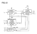
- the phase current detection unit 20 illustrated in FIG. 8 is deformed to be a phase current detection unit 20a illustrated in FIG. 12 .
- the phase current detection unit 20a can be used as the phase current detection unit 20 illustrated in FIG. 7 .
- the phase current detection unit 20a is supplied with i d and i q from the coordinate converter 21 instead of i d * and i q * .
- the phase current detection unit 20a includes the blocks 41, 42, and 44, and an intermediate phase current estimation block 43a.
- the estimation block 43a is supplied with the current values i d and i q , the rotor position ⁇ , and the voltage state value n.
- ⁇ -axis current i a and phase current i mid at second time that is later than first time are determined from the following equations (B1) to (B3) by using the latest rotor position ⁇ , and i d and i q based on a result of detection by the phase current detection unit 20a at the first time (i u , i v , and i w ).
- i mid or i a estimated by the estimation block 43a is delivered to the phase current calculation block 44.
- the a-axis current i a is an a-axis component of the detected motor current I a .
- the b-axis component of the motor current I a is referred to as b-axis current i b .
- i a and i b can be called detected current values on the ab-axis (or detected current values on the ab coordinate system).
- the phase current calculation block 44 can determine i u , i v , and i w by using i mid or i a based on i d and iq instead of i mid or i a * based on i d * and i q * when the value of S A or S B is 0.
- the a-axis current i a and the phase current i mid at the second time means i a and i mid to be calculated in the j-th control period, and the result of detection by the phase current detection unit 20a at the first time means i u , i v , and i w calculated in the (j-1)th control period (j denotes an integer). Therefore, i d and iq based on the result of detection by the phase current detection unit 20a at the first time indicate i d and iq calculated in the (j-1)th control period.
- Example 3 Example 3 will be described.
- the specified current values i d * and i q * on the dq-axis are used for estimating the phase current i mid of the intermediate phase.
- a specified ⁇ -axis current value i a * and a specified ⁇ -axis current value i ⁇ * that are specified current values on the ⁇ -axis may be used instead of i d * and i q * for estimating i mid
- i a * works as a target value of the ⁇ -axis current i a to be followed by the ⁇ -axis current value i a
- i ⁇ * works as a target value of the ⁇ -axis current i ⁇ to be followed by the ⁇ -axis current value i ⁇ .
- Example 3 the phase current detection unit 20 illustrated in FIG. 8 is deformed to be a phase current detection unit 20b illustrated in FIG. 13 .
- the phase current detection unit 20b is supplied with i a * and i ⁇ * instead of i d * and i q * .
- the phase current detection unit 20b is equipped with the blocks 41, 42, and 44, and an intermediate phase current estimation block 43b.
- the specified current values i d * and i q * on the dq-axis are converted into specified current values on the ⁇ -axis on the basis of the rotor position ⁇ so that the specified ⁇ -axis current value i a * and the specified ⁇ -axis current value i ⁇ * can be derived.
- the phase current detection unit 20b can be used as the phase current detection unit 20 illustrated in FIG. 7 .
- Example 3 is useful particularly in the case of constituting the current control loop on the ⁇ -axis instead of constituting the current control loop on the dq-axis like the motor drive system illustrated in FIG. 7 (the same is true in Example 4 that will be described later). Therefore, in the phase current detection unit 20b illustrated in FIG.
- the control block 41 is supplied with v a * and v ⁇ * so that the determination of the timings ST1 and ST2 and the determination of the values of n, S A and S B are performed on the basis of v a * and v ⁇ * .
- these determinations may be performed on the basis ofv u * , v v * , and V w * (the same is true in Example 4 that will be described later).
- the estimation block 43b determines the specified a-axis current value i a * and the phase current value i mid on the basis of i a * and ip * , and the voltage state value n from the control block 41 in accordance with the following equations (C1) and (C2).
- the equation (C2) is the same as the above equation (A3), and the estimation block 43b is the same as the estimation block 43 in the fundamental structure except that the deriving method of i a * is different. Therefore, the phase current value i mid estimated in accordance with the equation (C1) and the equation (C2) is supplied from the estimation block 43b to the block 44.
- Example 4 will be described.
- the specified current values i a * and i ⁇ * on the ⁇ -axis are used for estimating the phase current i mid of the intermediate phase.
- i ⁇ and i ⁇ that are to be said as detected current values on the ⁇ -axis may be used instead of i a * and i ⁇ * for estimating i mid .
- the phase current detection unit 20b illustrated in FIG. 13 is further deformed to be a phase current detection unit 20c illustrated in FIG. 14 .
- the phase current detection unit 20c is supplied with i a and i ⁇ instead of i a * and i ⁇ * .
- the phase current detection unit 20c is equipped with the blocks 41, 42, and 44, and an intermediate phase current estimation block 43c.
- the phase current detection unit 20c can be used as the phase current detection unit 20 illustrated in FIG. 7 .
- the current values i u , i v , and i w on the three-phase coordinate system are converted into current values on the ⁇ -axis so that the current values i ⁇ and i ⁇ can be obtained, and the current values i d and iq can be determined from the current values i a and i ⁇ , and ⁇ .
- the current values i ⁇ and i ⁇ obtained by the coordinate converter 21 is supplied to the estimation block 43c, and the voltage state value n is supplied from the control block 41 to the estimation block 43c.
- the a-axis current i a and the phase current i mid at the second time after the first time are derived from the following equations (C3) and (C4) by using i ⁇ and i ⁇ based on a result of detection by the phase current detection unit 20c at the first time (i u , i v , and i w ).
- the values i mid or i a estimated by the estimation block 43c is delivered to the phase current calculation block 44.
- the equation (C4) is the same as the above equation (B3). Therefore, when the equation (C4) is used, and when the voltage state value n is an odd number, ⁇ (2/3) times i a is substituted into i mid .
- the phase current calculation block 44 can determine i u , i v , and i w by using i mid or i a based on i ⁇ and i ⁇ when a value of S A or S B is 0.
- the a-axis current i a and the phase current i mid at the second time means i a and i mid to be calculated in the j-th control period, and a result of detection by the phase current detection unit 20c at the first time means i u , i v , and i w calculated in the (j-1)th control period (j denotes an integer). Therefore, i ⁇ and i ⁇ based on a result of detection by the phase current detection unit 20c at the first time means i ⁇ and i ⁇ calculated in the (j-1)th control period.
- estimation block 43c performs processes until estimation of the current value ia so that i a is supplied from the estimation block 43c to the block 44 instead of i mid . In this case, calculation of i mid based on i a is performed in the block 44.
- Example 5 will be described.
- i d and iq based on a result of detection (i u , i v , and i w ) by the phase current detection unit 20 at the first time are used for estimating the a-axis current i a and the phase current i mid at the second time.
- i ⁇ and i ⁇ based on a result of detection (i u , i v , and i w ) by the phase current detection unit 20 at the first time are used for estimating the a-axis current i a and the phase current i mid at the second time.
- i u * ,i v * , and i w * are obtained by converting i d * and iq * , or i ⁇ * and i ⁇ * into specified current values on the U, V, and W phase axes, and the method of using i u * ,i v * , and i w * is beneficial in a case where the current control loop is constituted on the U, V, and W phase axes in a motor drive system.
- the latter method is more desirable particularly in the case where the motor 1 is driven in the overmodulation region.
- a current waveform of each phase current is distorted from a sine wave.
- the specified current values (i d * , i q * , and the like) are on the assumption that the waveform of each phase current is a sine wave without a distortion.
- the distortion of the waveform is not taken into account.
- the control may be unstable.
- the influence of the distortion is reflected on the detected current values (i d , iq, and the like). Therefore, the control becomes stable when estimating i mid from the detected current value.
- the inverter 2 performs the PWM control so as to drive the motor 1.
- the control of supplying sine wave-like voltages to the armature windings 7u, 7v, and 7w of the motor 1 is called sine wave PWM control.
- a rectangular wave drive is used instead of the sine wave PWM control.
- voltages having a voltage waveform similar to a rectangular wave are applied to armature windings 7u, 7v, and 7w of the motor 1.
- the modulation method or PWM for realizing this rectangular wave drive is usually called overmodulation or overmodulation PWM.
- the overmodulation region means a state where the overmodulation is performed by the inverter 2.
- the motor 1 it is possible to decide on the basis of the specified voltage value whether or not the motor 1 is driven in the overmodulation region.
- whether or not the motor 1 is driven in the overmodulation region can be decided from a result of comparison between an amplitude of the specified voltage vector 320 and a predetermined voltage value (which is the highest voltage value that can be output by the sine wave PWM control and is a voltage value determined from the DC voltage value V dc ).
- a predetermined voltage value which is the highest voltage value that can be output by the sine wave PWM control and is a voltage value determined from the DC voltage value V dc .
- the method of estimating i mid may be switched as follows.
- i mid is estimated from the detected current values (e.g., i d and iq, or i ⁇ and i ⁇ ) like Example 2 (see FIG. 12 ) and Example 4 (see FIG. 14 ).
- i mid is estimated from the specified current value (e.g., i d * and i q * , or i ⁇ * and i ⁇ * ) like the fundamental structure (see FIG. 8 ) and Example 3 (see FIG. 13 ).
- the specified current value e.g., i d * and i q * , or i ⁇ * and i ⁇ *
- Example 6 will be described.
- the computing equation for estimating i mid is described supplementarily.
- the intermediate phase axis and the a-axis are agreed with each other, and a direction of the intermediate phase axis and a direction of the a-axis are the same or opposite depending on a value of n. Therefore, a relationship of the following equation (D1) is satisfied between i mid and the a-axis current i a .
- equation (D1) i a can be replaced with i a * for consideration. For instance, the state of FIG.
- the intermediate phase is the W-phase
- the a-axis i.e., a 1 -axis
- i mid - 1 n ⁇ 2 / 3 ⁇ i a
- i a , i b , i d , i q , i ⁇ and i ⁇ can be replaced with i a * , i b * , i d * , i q * , i ⁇ * and i ⁇ * , respectively.
- Example 7 will be described. In Example 7, a result of simulation on the phase current detection unit 20 illustrated in FIG. 8 will be described.
- curved lines 401 and 402 respectively indicate waveforms of the currents i dcA and i dcB obtained by the current detection block 42, and a curved line 403 indicates a waveform of the current i mid obtained by the estimation block 43.
- the horizontal axis represents a rotor position ⁇ , and a change in the left and right direction corresponds to a change of ⁇ .
- i dcA and i dcB in the period are zero.
- curved lines 410u, 410v, and 410w respectively indicate waveforms of phase currents i u , i v , and i w obtained by the phase current calculation block 44.
- the phase current of the intermediate phase can be estimated by a simple operation, and, by a simple addition or subtraction using the estimated value (see the above equations (A5a) and (A5b)), the phase current that is hardly detected by the current sensor 5 can be estimated. Therefore, compared with the methods described in JP-A-2009-055693 and the like, the operation load can be reduced. In addition, it is not necessary to correct the specified voltage value (pulse width) unlike the method described in JP-A-2003-189670 . Therefore, it is possible to avoid an increase of noise or vibration due to the correction, or a decrease of the usable voltage range.
- phase current that is hardly detected by the single shunt current detection method is estimated, an algorithm incorporated originally in the single shunt current detection method (algorism for calculating three-phase currents from i dcA and i dcB ) can be used as it is.
- the phase currents of two phases can be detected by the current sensor 5
- the detected current value is obtained from output of the current sensor 5 as principle so as to calculate the three-phase currents.
- the three-phase currents are calculated using the estimated current value (i dcA ' or i dcB ') instead of the detected current value. This switching can be realized by a simple processing.
- FIG. 17 is a general schematic diagram of a system interconnecting system according to the second embodiment.
- electric power generated by a solar cell is interconnected to a three-phase system using a three-phase inverter.
- a system interconnecting system incorporating a current controlled type voltage interconnecting three-phase inverter is exemplified.
- FIG. 17 illustrates an equivalent circuit of the solar cell 104.
- the solar cell 104 generates electricity from solar energy so as to generate a DC voltage.
- the DC voltage is generated between a positive output terminal 104a and a negative output terminal 104b, where the negative output terminal 104b is a low voltage side.
- the DC voltage between the positive output terminal 104a and the negative output terminal 104b is applied between terminals of a smoothing capacitor Cd so that the smoothing capacitor Cd stores electric charges corresponding to the DC voltage.
- the voltage detector 106 detects a voltage value of the voltage between the terminals of the smoothing capacitor Cd and sends the detected value to the inverter control device 103.
- the PWM inverter 102 illustrated in FIG. 17 (hereinafter simply referred to as "inverter 102") is a three-phase inverter that is the same as the inverter 2 illustrated in FIG. 1 and has the same internal structure as the inverter 2.
- the inverter 102 is equipped with a U-phase half bridge circuit, a V-phase half bridge circuit, and a W-phase half bridge circuit.
- Each of the half bridge circuits includes a pair of switching elements.
- the switching elements are connected in series between the positive output terminal 104a and the negative output terminal 104b, and the voltage between the terminals of the smoothing capacitor Cd is applied to each half bridge circuit.
- u, v and w are usually used as symbols indicating phases of a three-phase motor.
- symbols other than u, v, and w e.g., a, b, and c
- u, v, and w are used as symbols indicating phases of the inverter 102.
- connection node between the upper arm 8u and the lower arm 9u that are connected in series, the connection node between the upper arm 8v and the lower arm 9v that are connected in series, and the connection node between the upper arm 8w and the lower arm 9w that are connected in series are respectively connected to a terminal 112u that is an output terminal of the U-phase of the inverter 102, a terminal 112v that is an output terminal of the V-phase of the inverter 102, and a terminal 112w that is an output terminal of the W-phase of the inverter 102.
- field-effect transistors are shown as the switching elements in FIG. 17 , but they can be replaced with insulated gate bipolar transistors (IGBTs) or the like.
- the terminals 112u, 112v, and 112w are respectively connected to interconnecting points 130u, 130v, and 130w via an interconnecting reactor (inductor) and interior wiring.
- a reactance component of the interconnecting reactor and the interior wiring between the terminal 112u and the interconnecting point 130u is denoted by L c .
- L c reactance component of the interconnecting reactor and the interior wiring between the terminal 112u and the interconnecting point 130u
- L c reactance component of the interconnecting reactor and the interior wiring between the terminal 112u and the interconnecting point 130u
- L c reactance component of the interconnecting reactor and the interior wiring between the terminal 112u and the interconnecting point 130u
- L c reactance component of the interconnecting reactor and the interior wiring between the terminal 112u and the interconnecting point 130u
- L c reactance component of the interconnecting reactor and the interior wiring between the terminal 112u and the interconnecting point 130u
- L c reactance component
- Numeral 140 denotes an electric power system for supplying three-phase AC power (system side power supply).
- the electric power system 140 can be broken into three AC voltage sources 140u, 140v, and 140w for consideration.
- Each of the AC voltage sources 140u, 140v, and 140w outputs AC voltage of an angular frequency (angular speed) ⁇ s with respect to a reference point 141.
- phases of the AC voltages output from the AC voltage sources 140u, 140v, and 140w are different from each other by 120 degrees in electrical angle.
- the electric power system 140 delivers output voltages of the AC voltage sources 140u, 140v, and 140w with respect to the reference point 141 from terminals 142u, 142v, and 142w, respectively.
- the terminals 142u, 142v, and 142w are respectively connected to the interconnecting points 130u, 130v, and 130w via outside wiring.
- a reactance component and a resistance component of line impedance of each outside wiring are denoted by L s and R s , respectively.
- Loads such as home appliances are connected between different interconnecting points.
- a load 135 that is a linear load is connected between the interconnecting points 130u and 130v
- a load 136 that is a nonlinear load is connected between the interconnecting points 130v and 130w. Therefore, the load 135 is driven by a driving voltage that is the voltage between the interconnecting points 130u and 130v, and the load 136 is driven by a driving voltage that is the voltage between the interconnecting points 130v and 130w.
- the linear load is a load that follows Ohm's Law
- the nonlinear load is a load that does not follow Ohm's Law.
- a load including a rectifying circuit like an AC/DC converter is supposed as the load 136.
- the inverter 102 supplies the PWM signal (pulse width modulated signal) based on the specified three-phase voltage values generated by the inverter control device 103 to control terminals (bases or gates) of the switching elements in the inverter 102 so that the switching elements perform switching actions.
- PWM signal pulse width modulated signal
- the specified three-phase voltage values generated by the inverter control device 103 include the specified U-phase voltage value v u * , the specified V-phase voltage value v v * , and the specified W-phase voltage value v w * , so that voltage levels (voltage values) of the U-phase voltage v u , the V-phase voltage v v , and the W-phase voltage v w are specified by v u * , v v * , and v w * , respectively.
- the DC voltage from the solar cell 104 is converted into the three-phase AC voltages by the PWM modulation (pulse width modulation) with the switching action of each switching element in the inverter 102.
- PWM modulation pulse width modulation
- the system interconnection between the solar cell 104 as the DC power supply and the electric power system 140 is performed, so that AC power corresponding to the three-phase AC voltages from the inverter 102 are supplied to the loads 135 and 136 while interconnecting to the electric power system 140.
- the current sensor 105 detects current flowing in the bus line 113 of the inverter 102.
- the bus current in the second embodiment indicates current flowing in the bus line 113.
- the bus current includes a DC component, which can be interpreted to be a DC current.
- the low voltage sides of the lower arms 9u, 9v, and 9w are connected to each other and are connected to the negative output terminal 104b of the solar cell 104.
- the wiring line to which the low voltage sides of the lower arms 9u, 9v, and 9w are commonly connected is the bus line 113, and the current sensor 105 is disposed in series to the bus line 113.
- the current sensor 105 transmits the signal indicating a current value of the detected bus current to the inverter control device 103.
- the inverter control device 103 generates the above-mentioned specified three-phase voltage values on the basis of an output signal of the current sensor 105.
- the current sensor 105 is, for example, a shunt resistor, a current transformer, or the like.
- the U-phase voltage v u , the V-phase voltage v v and the W-phase voltage v w in the motor drive system mean voltages at the terminals 12u, 12v, and 12w viewed from the neutral point 14 in FIG. 1
- the U-phase voltage v u , the V-phase voltage v v , and the W-phase voltage v w in the second embodiment respectively indicate voltages at the terminals 112u, 112v, and 112w viewed from a reference potential point having a certain fixed potential.
- the reference point 141 can be regarded as the above-mentioned reference potential point.
- phase voltage Each of the U-phase voltage, the V-phase voltage, and the W-phase voltage is referred to (or they are collectively referred to) as a phase voltage.
- currents flowing via the terminals 112u, 112v, and 112w are referred to as U-phase current i u , V-phase current i v , and W-phase current i w , respectively, and each of them is referred to (or they are collectively referred to) as a phase current.
- phase currents it is supposed that current flowing out from the terminal 112u, 112v, or 112w has a positive polarity.
- the maximum phase (maximum voltage phase), the intermediate phase (intermediate voltage phase), and the minimum phase (minimum voltage phase) are defined similarly to the motor drive system.
- the switching actions of the individual arms in the inverter 102 based on v u * , v v * , and v w * are the same as those in the motor drive system.
- the inverter 102 is similar to the inverter 2 of the motor drive system and controls ON and OFF of each arm in accordance with a result of comparison between the carrier signal CS and v u * , v v * , or v w * .
- interconnection current currents output from the inverter 102 via the terminals 112u, 112v, and 112w are collectively referred to as "interconnection current".
- the U-phase current i u , the V-phase current i v , and the W-phase current i w respectively correspond to the U-phase axis component, the V-phase axis component, and the W-phase axis component of the interconnection current. Therefore, combined current of i u , i v , and i w is the interconnection current.
- FIG. 18 illustrates a general schematic diagram of the system interconnecting system according to the second embodiment, which includes an internal block diagram of the inverter control device 103.
- the inverter control device 103 includes portions denoted by numerals 150 to 156.
- the output signal of the current sensor 105 is used for detecting each phase current, and the detected three-phase phase currents are converted into active current and reactive current (i.e., P-Q conversion of the interconnection current is performed).
- the specified voltage vector is generated so that a voltage value of the voltage between the terminals of the smoothing capacitor Cd is maintained to a desired value and that the reactive current becomes zero, and the specified three-phase voltage values (v u * , v v * , and v w * ) are generated from the specified voltage vector so as to control the inverter 102.
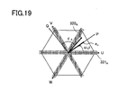
- FIG. 19 is a space vector diagram illustrating a relationship among the U-phase axis, the V-phase axis, and the W-phase axis as fixed axes, and a P-axis and a Q-axis as rotating axis.
- the angular frequency (angular speed) in rotation of the P-axis is the same as the angular frequency ⁇ s of the AC voltage output from the AC voltage sources 140u, 140v, and 140w.
- the combined voltage of individual voltages at the interconnecting points 130u, 130v, and 130w illustrated in FIG. 17 is regarded as a vector quantity on a two-dimensional coordinate plane, and the voltage vector is denoted by e c . If the inverter 102 outputs current having the same phase as e c (current expressed by the current vector having the same direction as e c ), the inverter 102 outputs only active power (in this case, reactive power is supplied from the electric power system 140).
- the direction of the P-axis is the same as the direction of the voltage vector e c (therefore, the voltage vector e c is on the P-axis). Further, the Q-axis is taken to be the phase leading the P-axis by 90 degrees in electrical angle.
- the P-axis and the Q-axis are collectively referred to as a PQ-axis, and a coordinate system in which the P-axis and the Q-axis are selected as its coordinate axes is referred to as a PQ coordinate system.
- a phase of the output voltage of the inverter 102 leads the voltage vector e c by the interconnecting reactor expressed by L c .
- a vector denoted by 320 A is the specified voltage vector in the second embodiment.
- a phase of the specified voltage vector 320 A viewed from the Q-axis in a counterclockwise direction is denoted by ⁇ A .
- the counterclockwise direction is regarded as the phase leading direction so that ⁇ A ⁇ 0 is satisfied.
- a phase of the specified voltage vector 320 A with respect to the U-phase axis is expressed by ( ⁇ s t+ ⁇ /2+ ⁇ A ).
- a P-axis component and a Q-axis component of the specified voltage vector 320 A are denoted by vP * and vQ * , respectively.
- the asterisk region 321 A with hatching that includes a vicinity of the U-phase axis, a vicinity of the V-phase axis, and a vicinity of the W-phase axis indicates the region where phase currents of two phases cannot be detected from the bus current similarly to the region 321 in FIG. 5 .
- the ⁇ - and ⁇ -axes, the a n -axis, and the b n -axis are defined.
- the inverter control device 103 sets one of a 0 to a 5 -axes as the a-axis and sets one of b 0 - to b 5 -axes as the b-axis by the same method as described above in the first embodiment in accordance with the voltage state value n.
- the portions constituting the inverter control device 103 illustrated in FIG. 18 update the specified values (vP * , vQ * , and the like) or the state quantities (iP, iQ, and the like) that are calculated (or detected) and output by themselves at a predetermined control period, so as to perform necessary operation using latest values that can be obtained at the time point.
- the current sensor 105 detects bus current and outputs a signal indicating a current value of the bus current. Also in the second embodiment, the bus current is denoted by i dc .
- the output signal of the current sensor 105 is sent to the phase current detection unit 150.
- the phase current detection unit 150 is supplied with bus current i dc detected by the current sensor 105, specified three-phase voltage values v u * , v v * , and v w * from a coordinate converter 155, a specified P-axis current value iP * from a DC voltage controller 153, a specified Q-axis current value iQ * , and a phase ⁇ s t.
- the phase current detection unit 150 calculates current values i u , i v , and i w of the phase currents on the basis of the supplied values, and outputs a result of the calculation.
- the coordinate converter 151 converts the current values i u , i v , and i w from the phase current detection unit 150 into a current value on the PQ-axis on the basis of the phase ⁇ s t so as to calculate a P-axis current value iP and a Q-axis current value iQ.
- iP is the P-axis component in the interconnection current and indicates active current in the interconnection current.
- iQ is the Q-axis component in the interconnection current and indicates reactive current in the interconnection current.
- iP and iQ calculated at a certain timing indicate instantaneous values of the active current and the reactive current at that timing.
- iP and iQ are calculated in accordance with the following equation (E1).
- iP iQ 2 ⁇ sin ⁇ S ⁇ t + ⁇ / 3 sin ⁇ S ⁇ t cos ⁇ S ⁇ t + ⁇ / 3 cos ⁇ S ⁇ t ⁇ i u i v
- the phase ⁇ s t corresponds to a phase of the output voltage of the inverter 102.
- a lapse time from a time point when the U-phase axis agrees with the P-axis is denoted by t, and a phase of the P-axis viewed from the U-phase axis is expressed by ⁇ s t. Therefore, the phase ⁇ s t is determined from a phase of the U-phase voltage V u .
- the DC voltage controller 153 is supplied with the voltage Ed between the terminals of the smoothing capacitor Cd that is detected by the voltage detector 106 and the specified DC voltage value Ed * indicating a target value of the voltage between the terminals Ed.
- the specified DC voltage value Ed * becomes the same as Ed for obtaining a maximum power from the solar cell 104 (in other words, Ed for maximize the output power of the inverter 102).
- the DC voltage controller 153 calculates and outputs the specified value (specified P-axis current value) iP * of the active current so that (Ed-Ed * ) is converged to zero by proportional plus integral control.
- the specified value (specified Q-axis current value) iQ * of the reactive current is set to zero.
- iP * works as a target value of the P-axis current iP to be followed by the P-axis current value iP.
- iQ * works as a target value of the Q-axis current iQ to be followed by the Q-axis current value iQ.
- An active current controller 154 performs the proportional plus integral control using iP * from the DC voltage controller 153 and iP from the coordinate converter 151 so that the current error (iP * -iP) is converged to zero, so as to calculate the specified P-axis voltage value vP * .
- a reactive current controller 152 performs the proportional plus integral control using given iQ * and iQ from the coordinate converter 151 so that the current error (iQ * -iQ) is converged to zero, so as to calculate the specified Q-axis voltage value vQ * .
- vP * works as a target value of the P-axis voltage vP to be followed by the P-axis voltage value vP.
- vQ * works as a target value of the Q-axis voltage vQ to be followed by the Q-axis voltage value vQ.
- vP and vQ indicate a P-axis component and a Q-axis component of the output voltage vector of the inverter 102, respectively.
- the output voltage vector of the inverter 102 means a vector quantity corresponding to the combined voltage of the U-phase, V-phase, and W-phase voltages of the inverter 102.
- the specified voltage vector 320 A illustrated in FIG. 19 works as a target of this output voltage vector, and vP * and vQ * are a P-axis component and a Q-axis component of the specified voltage vector 320 A . Therefore, the active current controller 154 and the reactive current controller 152 work as the specified voltage vector generation unit which generates the specified voltage vector 320 A .
- the coordinate converter 155 converts specified voltage value vP * and vQ * on the PQ-axis from the controllers 154 and 152 into specified values on the U, V, and W phase axes on the basis of the phase ⁇ s t, so as to calculates v u * , v v * , and v w * that are the U-phase axis, V-phase axis, and W-phase axis components of the specified voltage vector 320 A.
- a PWM signal generator 156 generates the PWM signal for each switching element (arm) in the inverter 102 on the basis of the specified three-phase voltage values v u * , v v * , and v w * from the coordinate converter 155, so that the U-phase, V-phase, and W-phase voltage values v u , v v , and v w become voltage values following the specified values v u * , v v * , and v w * , respectively.
- the inverter 102 controls switching of each switching element in the inverter 102 in accordance with the PWM signal, so as to output the U-phase, V-phase, and W-phase voltages corresponding to the specified three-phase voltage values v u * , v v * , and v w * . Note that it is possible to dispose the PWM signal generator 156 not in the inverter control device 103 but in the inverter 102.
- FIG. 20 is an internal block diagram of the phase current detection unit 150.
- the phase current detection unit 150 includes a control block 161, a current detection block 162, an intermediate phase current estimation block 163, and a phase current calculation block 164.
- the control block 161 sets the sampling timings ST1 and ST2 and the voltage state value n, and generates a signal S A indicating whether or not phase current of the maximum phase can be detected from the output signal of the current sensor 105, as well as a signal S B indicating whether or not phase current of the minimum phase can be detected from the output signal of the current sensor 105.
- the detection block 162 is constituted of an A/D converter (not shown) which converts an analog output signal from the current sensor 105 into a digital signal.
- the output signal of the current sensor 105 i.e., current value of the bus current i dc
- the A/D converter determines the current values i dCA and i dCB .
- the current values i dCA and i dCB correspond to a detected value of the phase current of the maximum phase and a detected value of the phase current of the minimum phase, respectively.
- the estimation block 163 converts the specified current values iP * and iQ * on the PQ-axis into the specified current values on the ab-axis on the basis of the phase ⁇ s t, so as to estimate the specified a-axis current value i a * that is an a-axis component of the specified voltage vector 320 A .
- the specified a-axis current value i a * is one of specified current values on the ab-axis (in other words, specified current values on the ab coordinate system).
- the ab coordinate system can be said to be a coordinate system rotating step by step of 60 degrees each in accordance with a phase ( ⁇ + ⁇ /2+ ⁇ A ) of the specified voltage vector 320 A with respect to the U-phase axis, and can also be said to be a coordinate system rotating step by step of 60 degrees each in accordance with phase voltages of three phases (U, V, and W phase voltages).
- the estimation block 163 estimates the phase current i mid of the intermediate phase from i a * . When the value of n is known, which phase is the intermediate phase is known.
- iP * , iQ * , and ⁇ s t into the relational expression of iP * , iQ * , i u * , i v * , and i w * , so as to estimate i mid .
- the estimated phase current value i mid is given to the phase current calculation block 164. Note that it is possible to adopt a structure in which the estimation block 163 performs processes until estimation of the specified value i a * so that i a * is given from the estimation block 163 to the block 164 instead of i mid . In this case, calculation of i mid based on i a * is performed in the block 164.
- the phase current calculation block 164 calculates the U-phase, V-phase, and W-phase current values i u , i v , and i w on the basis of i dcA and i dcB from the detection block 162, i mid from the estimation block 163, and n, S A , and S B from the control block 161.
- the d-axis, q-axis, i d * , i q * , i d , i q , ⁇ , ⁇ , and 320 in the first embodiment should be read as P-axis, Q-axis, iP * , iQ * , iP, iQ, ⁇ s t, ⁇ A , and 320 A , respectively, and a difference of reference numeral between portions having the same name should be neglected appropriately (e.g., the difference between numerals (43and 163) of the intermediate phase current estimation blocks in FIGS. 8 and 20 is neglected appropriately).
- the control performed by the inverter control device 103 of the system interconnecting system can be said to be control of the active current and the reactive current, and it can also be said to be control of the active power and the reactive power.
- the AC voltage from the electric power system 140 is an AC voltage having a substantially constant amplitude, and therefore the control of the active current and the reactive current to be desired values while interconnecting to the AC voltage means to control the active power and the reactive power to be desired values (the active power is the product of the voltage and the active current, and the reactive power is the product of the voltage and the reactive current). Therefore, the inverter control device 103 as one type of the inverter control device can be called a current control device and also a power control device.
- the solar cell 104 is exemplified as an example of the DC power supply to the inverter 102, a fuel cell or a wind turbine generator may be used instead of the solar cell 104.
- the specific structures of the system interconnecting system and the phase current detection unit illustrated in FIGS. 18 and 20 may be modified in accordance with various technical matters described above in the first embodiment (i.e., the techniques described above in Examples of the first embodiment may be applied to the system interconnecting system).
- Example 2 of the first embodiment it is possible to adopt a structure in which iP and iQ to be said to be current detected values on the PQ-axis are supplied to the estimation block 163, so that the latest phase ⁇ s t, and iP and iQ based on a result of detection (i u , i v , and i w ) by the phase current detection unit 150 at the first time are used for estimating the a-axis current i a and the phase current i mid at the second time after the first time.
- Example 5 of the first embodiment it is possible to adopt a structure in which the estimation block 163 estimates the a-axis current i a and the phase current i mid at the second time directly from a result of detection (i u , i v , and i w ) by the phase current detection unit 150 at the first time. It is also possible to adopt a structure in which the a-axis current i a and the phase current i mid at the second time are estimated directly from i u * ,i v * , and i w * at the first time.
- the rotor position ⁇ and the rotational speed ⁇ are detected by using the position sensor 30.
- the inverter 2 performs the three-phase modulation.
- the present invention does not depend on a modulation method of the inverter 2, the inverter 2 may perform modulation other than the three-phase modulation (such as two-phase modulation).
- any method can be used for deriving all values to be derived, including various specified values (v d * , v q * , vP * , and vQ * ) and state quantities (i d , i q , iP, iQ, and the like).
- the values may be derived by calculation by the motor control device 3 or the inverter control device 103, or may be derived from table data that are set in advance.
- a part or a whole of functions of the motor control device 3 is realized by using software (program) incorporated in an all-purpose microcomputer or the like. The same is true for the inverter control device 103.
- the block diagram indicating the structure of individual portions of the motor control device 3 or the inverter control device 103 corresponds to a functional block diagram.
- software program
- only hardware or a combination of software and hardware may be used for constituting the motor control device 3 or the inverter control device 103.
- the motor control device 3 and the motor drive system according to the present invention may be incorporated in any electric equipment that uses a motor.
- the electric equipment may include, for example, an electric vehicle (electric car, electric motorcycle, electric bike, and the like), an air conditioner (for house, vehicle or the like), a washing machine, and a compressor (for refrigerator or the like), which are driven by the motor.
Landscapes
- Engineering & Computer Science (AREA)
- Power Engineering (AREA)
- Control Of Ac Motors In General (AREA)
- Control Of Motors That Do Not Use Commutators (AREA)
Applications Claiming Priority (1)
| Application Number | Priority Date | Filing Date | Title |
|---|---|---|---|
| JP2009279386A JP2011125107A (ja) | 2009-12-09 | 2009-12-09 | モータ制御装置、モータ駆動システム及びインバータ制御装置 |
Publications (2)
| Publication Number | Publication Date |
|---|---|
| EP2333948A2 true EP2333948A2 (fr) | 2011-06-15 |
| EP2333948A3 EP2333948A3 (fr) | 2017-03-22 |
Family
ID=43795152
Family Applications (1)
| Application Number | Title | Priority Date | Filing Date |
|---|---|---|---|
| EP10015391.5A Withdrawn EP2333948A3 (fr) | 2009-12-09 | 2010-12-07 | Dispositif de contrôle d'onduleur et système d'entraînement de moteur |
Country Status (4)
| Country | Link |
|---|---|
| US (1) | US20110133678A1 (fr) |
| EP (1) | EP2333948A3 (fr) |
| JP (1) | JP2011125107A (fr) |
| CN (1) | CN102097999B (fr) |
Cited By (1)
| Publication number | Priority date | Publication date | Assignee | Title |
|---|---|---|---|---|
| CN104777343A (zh) * | 2015-04-20 | 2015-07-15 | 台州市菱士达电器有限公司 | 一种变频器中的三相电流检测方法及电路 |
Families Citing this family (37)
| Publication number | Priority date | Publication date | Assignee | Title |
|---|---|---|---|---|
| CN105591583B (zh) | 2010-03-08 | 2019-06-28 | 江森自控科技公司 | 具有自适应磁链估计的马达控制系统和方法 |
| DE102010023038A1 (de) * | 2010-06-08 | 2011-12-08 | Repower Systems Ag | Windenergieanlage und Verfahren zum Betreiben einer Windenergieanlage |
| DE102010042908A1 (de) * | 2010-10-26 | 2012-04-26 | Robert Bosch Gmbh | Verfahren und Steuereinheit zur pulsweitenmodulierten Steuerung von Schaltelementen eines Pulswechselrichters |
| CN102088271B (zh) * | 2010-12-20 | 2013-03-20 | 广东美的电器股份有限公司 | 一种无传感器正弦直流变频电流采样方法 |
| FR2969867B1 (fr) * | 2010-12-28 | 2015-03-20 | Renault Sa | Systeme de commande d'un ondulateur de tension alimentant un moteur electrique multiphase de vehicule automobile. |
| US8742712B2 (en) * | 2011-01-26 | 2014-06-03 | GM Global Technology Operations LLC | Methods, systems and apparatus for controlling third harmonic voltage when operating a multi-phase machine in an overmodulation region |
| CN102545889B (zh) * | 2011-12-19 | 2014-07-30 | 西安赛博电气有限责任公司 | 基于瞬时无功功率理论的闭环锁相方法及锁相器 |
| DK2607692T4 (da) * | 2011-12-22 | 2025-08-18 | Siemens Gamesa Renewable Energy As | Fremgangsmåde til bestemmelse af et spændingsbegrænsningsområde |
| JP2013162536A (ja) * | 2012-02-01 | 2013-08-19 | Mitsubishi Electric Corp | 電力変換装置 |
| US9211806B2 (en) | 2012-04-23 | 2015-12-15 | GM Global Technology Operations LLC | Methods, systems and apparatus for generating voltage commands used to control operation of a permanent magnet machine |
| JP6033424B2 (ja) * | 2012-06-26 | 2016-11-30 | 日産自動車株式会社 | 可変起磁力型回転電機、及び可変起磁力型回転電機の制御装置 |
| CN102769297B (zh) * | 2012-07-12 | 2014-12-03 | 华北电力大学 | 一种基于全控型逆变器的次同步振荡抑制方法 |
| JP5757304B2 (ja) * | 2012-11-01 | 2015-07-29 | 株式会社デンソー | 交流電動機の制御装置 |
| JP2014138526A (ja) * | 2013-01-18 | 2014-07-28 | Hitachi Appliances Inc | インバータ制御装置およびインバータ制御装置を備える圧縮機 |
| KR20150075626A (ko) * | 2013-12-26 | 2015-07-06 | 동부대우전자 주식회사 | 세탁기의 진동 저감 장치 및 방법 |
| JP5865930B2 (ja) * | 2014-03-07 | 2016-02-17 | 三菱電機株式会社 | モータ制御装置 |
| US9802642B2 (en) * | 2014-04-11 | 2017-10-31 | Steering Solutions Ip Holding Corporation | Phase current measurement diagnostic |
| JP6342293B2 (ja) * | 2014-10-20 | 2018-06-13 | 株式会社東芝 | 中性点クランプ形電力変換装置およびその制御方法 |
| JP6390489B2 (ja) * | 2015-03-30 | 2018-09-19 | 株式会社デンソー | インバータの制御装置 |
| JP6372424B2 (ja) * | 2015-06-05 | 2018-08-15 | 株式会社安川電機 | 電力変換装置および電流検出方法 |
| JP6341165B2 (ja) * | 2015-09-01 | 2018-06-13 | 株式会社安川電機 | 電力変換装置、相電流検出装置および相電流検出方法 |
| US11370307B2 (en) | 2016-06-30 | 2022-06-28 | Borg Warner Gateshead Limited | Method and apparatus for controlling an electric motor |
| GB2551822B (en) * | 2016-06-30 | 2018-08-22 | Sevcon Ltd | Methods and apparatus for controlling an electric motor |
| US10270327B1 (en) | 2017-10-13 | 2019-04-23 | Deere & Company | Voltage sensor-less position detection in an active front end |
| US10295581B2 (en) * | 2017-10-13 | 2019-05-21 | Deere & Company | Voltage sensor-less position detection in an active front end |
| JP6854404B2 (ja) * | 2018-02-21 | 2021-04-07 | パナソニックIpマネジメント株式会社 | インバータ制御装置 |
| EP3588107B1 (fr) * | 2018-06-21 | 2020-12-09 | ABB Power Grids Switzerland AG | Procédé et dispositif de calcul des courants d'enroulement du cote delta d'un transformateur |
| DE102018213939A1 (de) * | 2018-08-17 | 2020-02-20 | Continental Teves Ag & Co. Ohg | Verfahren zum Betreiben eines permanentmagneterregten Synchronmotors, elektronische Steuerungsvorrichtung, Motoranordnung und Speichermedium |
| CN109600055B (zh) * | 2018-12-14 | 2020-05-15 | 苏州蓝石新动力有限公司 | 一种获取逆变桥母线电流值的方法及装置 |
| DE112020006987T5 (de) * | 2020-03-27 | 2023-01-12 | Mitsubishi Electric Corporation | Drei-Stufen-Leistungswandler und Verfahren zum Steuern eines Zwischenpotentials einer Gleichstromleistungszufuhreinheit |
| JP2024509514A (ja) * | 2021-03-03 | 2024-03-04 | ジーエイチエスピー・インコーポレイテッド | 潤滑/冷却アセンブリ内に位置するスマートポンプのための制御システム |
| CN113224992B (zh) * | 2021-04-27 | 2022-04-22 | 广东工业大学 | 一种抑制永磁同步电机单电阻采样电流畸变的方法 |
| US11539283B1 (en) * | 2021-06-04 | 2022-12-27 | Rockwell Automation Technologies, Inc. | System and method for reducing delay in the modulation of a multi-phase output voltage from an inverter |
| CN118266156A (zh) * | 2021-10-26 | 2024-06-28 | 日立安斯泰莫株式会社 | 电动机控制装置、电动机控制方法、混合动力系统、升压转换器系统、电动助力转向系统 |
| US12015366B2 (en) * | 2022-04-08 | 2024-06-18 | Abb Schweiz Ag | Parallel synchronous machines with single motor drive |
| WO2025122562A2 (fr) * | 2023-12-05 | 2025-06-12 | Magna International Inc. | Système et procédé de commande hybride d'entraînement de pmsm à l'aide de deux capteurs de courant |
| CN119881643B (zh) * | 2025-03-18 | 2025-09-12 | 西北工业大学 | 基于电流矢量的永磁同步电机逆变器开路故障诊断方法 |
Citations (3)
| Publication number | Priority date | Publication date | Assignee | Title |
|---|---|---|---|---|
| JP2003189670A (ja) | 2001-12-14 | 2003-07-04 | Matsushita Electric Ind Co Ltd | 電動機駆動装置及びそれを用いた冷凍装置 |
| JP2008283848A (ja) | 2007-04-13 | 2008-11-20 | Sanyo Electric Co Ltd | モータ制御装置 |
| JP2009055693A (ja) | 2007-08-27 | 2009-03-12 | Hitachi Ltd | 電力変換装置 |
Family Cites Families (7)
| Publication number | Priority date | Publication date | Assignee | Title |
|---|---|---|---|---|
| JP4497149B2 (ja) * | 2005-12-16 | 2010-07-07 | パナソニック株式会社 | インバータ装置 |
| JP4429338B2 (ja) * | 2006-09-11 | 2010-03-10 | 三洋電機株式会社 | モータ制御装置、電流検出ユニット |
| JP4956123B2 (ja) * | 2006-09-28 | 2012-06-20 | 三洋電機株式会社 | モータ制御装置 |
| JP4988374B2 (ja) * | 2007-02-15 | 2012-08-01 | 三洋電機株式会社 | モータ制御装置 |
| JP2009055748A (ja) * | 2007-08-29 | 2009-03-12 | Sanyo Electric Co Ltd | 電流検出ユニット及びモータ制御装置 |
| JP5014034B2 (ja) * | 2007-09-12 | 2012-08-29 | オムロンオートモーティブエレクトロニクス株式会社 | 多相交流モータ駆動装置 |
| JP4746667B2 (ja) * | 2008-11-26 | 2011-08-10 | 本田技研工業株式会社 | 電動機の相電流推定装置および電動機の磁極位置推定装置 |
-
2009
- 2009-12-09 JP JP2009279386A patent/JP2011125107A/ja active Pending
-
2010
- 2010-12-07 CN CN201010583679.3A patent/CN102097999B/zh not_active Expired - Fee Related
- 2010-12-07 EP EP10015391.5A patent/EP2333948A3/fr not_active Withdrawn
- 2010-12-09 US US12/964,365 patent/US20110133678A1/en not_active Abandoned
Patent Citations (3)
| Publication number | Priority date | Publication date | Assignee | Title |
|---|---|---|---|---|
| JP2003189670A (ja) | 2001-12-14 | 2003-07-04 | Matsushita Electric Ind Co Ltd | 電動機駆動装置及びそれを用いた冷凍装置 |
| JP2008283848A (ja) | 2007-04-13 | 2008-11-20 | Sanyo Electric Co Ltd | モータ制御装置 |
| JP2009055693A (ja) | 2007-08-27 | 2009-03-12 | Hitachi Ltd | 電力変換装置 |
Non-Patent Citations (1)
| Title |
|---|
| YAMADA: "IEEJ National Convention Lecture", vol. 4-076, March 2007, INSTITUTE OF ELECTRICAL ENGINEERS OF JAPAN, article "Current Controlled Type Sinusoidal Voltage Interconnecting Three-Phase Inverter", pages: 115 |
Cited By (2)
| Publication number | Priority date | Publication date | Assignee | Title |
|---|---|---|---|---|
| CN104777343A (zh) * | 2015-04-20 | 2015-07-15 | 台州市菱士达电器有限公司 | 一种变频器中的三相电流检测方法及电路 |
| CN104777343B (zh) * | 2015-04-20 | 2017-07-14 | 台州市菱士达电器有限公司 | 一种变频器中的三相电流检测方法及电路 |
Also Published As
| Publication number | Publication date |
|---|---|
| CN102097999A (zh) | 2011-06-15 |
| EP2333948A3 (fr) | 2017-03-22 |
| CN102097999B (zh) | 2015-01-28 |
| JP2011125107A (ja) | 2011-06-23 |
| US20110133678A1 (en) | 2011-06-09 |
Similar Documents
| Publication | Publication Date | Title |
|---|---|---|
| US20110133678A1 (en) | Motor control device, motor drive system and inverter control device | |
| EP2164156B1 (fr) | Appareil de contrôle d'inverseur et système d'entraînement de moteur | |
| US7728537B2 (en) | Motor control device and current detecting unit | |
| US7898197B2 (en) | Motor control device | |
| US6700343B2 (en) | Motor controller | |
| US8283881B2 (en) | Methods, systems and apparatus for synchronous current regulation of a five-phase machine | |
| JP3982232B2 (ja) | 同期発電機のセンサレス制御装置と制御方法 | |
| US8040086B2 (en) | Current detector unit and motor control device | |
| JP2004048868A (ja) | 同期電動機の速度制御装置 | |
| US9595902B2 (en) | Methods, systems and apparatus for adjusting modulation index to improve linearity of phase voltage commands | |
| CN102195552A (zh) | 近似多相电机中基波与三次谐波峰值合计电压的方法、系统和装置 | |
| CN106533306B (zh) | 永磁同步电机系统及其过调制控制方法和装置 | |
| JP2018170928A (ja) | モータ制御装置 | |
| US8917040B2 (en) | AC motor control apparatus | |
| JP2010068581A (ja) | 電動機駆動装置 | |
| JP4581603B2 (ja) | 電動機駆動装置 | |
| JP2019170095A (ja) | モータ制御装置 | |
| EP3787174B1 (fr) | Dispositif de génération de motif d'impulsion | |
| Jin et al. | Simulation study of AC motor speed sensorless vector control system based on SVPWM | |
| JP2019170089A (ja) | モータ制御装置 | |
| JP6962267B2 (ja) | パルスパターン生成装置 | |
| JP2016136823A (ja) | 電力変換制御装置、電力変換ユニット及び電力システム | |
| KR20110118502A (ko) | 동기 전동기의 위치 추정 방법 및 이를 이용한 전동기 구동장치 |
Legal Events
| Date | Code | Title | Description |
|---|---|---|---|
| PUAI | Public reference made under article 153(3) epc to a published international application that has entered the european phase |
Free format text: ORIGINAL CODE: 0009012 |
|
| AK | Designated contracting states |
Kind code of ref document: A2 Designated state(s): AL AT BE BG CH CY CZ DE DK EE ES FI FR GB GR HR HU IE IS IT LI LT LU LV MC MK MT NL NO PL PT RO RS SE SI SK SM TR |
|
| AX | Request for extension of the european patent |
Extension state: BA ME |
|
| PUAL | Search report despatched |
Free format text: ORIGINAL CODE: 0009013 |
|
| AK | Designated contracting states |
Kind code of ref document: A3 Designated state(s): AL AT BE BG CH CY CZ DE DK EE ES FI FR GB GR HR HU IE IS IT LI LT LU LV MC MK MT NL NO PL PT RO RS SE SI SK SM TR |
|
| AX | Request for extension of the european patent |
Extension state: BA ME |
|
| RIC1 | Information provided on ipc code assigned before grant |
Ipc: G01R 19/00 20060101ALI20170215BHEP Ipc: H02M 7/5387 20070101ALI20170215BHEP Ipc: H02P 27/08 20060101ALI20170215BHEP Ipc: H02P 21/00 20160101AFI20170215BHEP |
|
| STAA | Information on the status of an ep patent application or granted ep patent |
Free format text: STATUS: THE APPLICATION HAS BEEN PUBLISHED |
|
| STAA | Information on the status of an ep patent application or granted ep patent |
Free format text: STATUS: THE APPLICATION IS DEEMED TO BE WITHDRAWN |
|
| 18D | Application deemed to be withdrawn |
Effective date: 20170923 |