EP2334254B1 - Appareil et procédés destinés à tester la polissabilité de matériaux - Google Patents
Appareil et procédés destinés à tester la polissabilité de matériaux Download PDFInfo
- Publication number
- EP2334254B1 EP2334254B1 EP09818464.1A EP09818464A EP2334254B1 EP 2334254 B1 EP2334254 B1 EP 2334254B1 EP 09818464 A EP09818464 A EP 09818464A EP 2334254 B1 EP2334254 B1 EP 2334254B1
- Authority
- EP
- European Patent Office
- Prior art keywords
- specimen
- polishing
- roughness
- platen
- shall
- Prior art date
- Legal status (The legal status is an assumption and is not a legal conclusion. Google has not performed a legal analysis and makes no representation as to the accuracy of the status listed.)
- Not-in-force
Links
Images









Classifications
-
- G—PHYSICS
- G01—MEASURING; TESTING
- G01B—MEASURING LENGTH, THICKNESS OR SIMILAR LINEAR DIMENSIONS; MEASURING ANGLES; MEASURING AREAS; MEASURING IRREGULARITIES OF SURFACES OR CONTOURS
- G01B5/00—Measuring arrangements characterised by the use of mechanical techniques
- G01B5/28—Measuring arrangements characterised by the use of mechanical techniques for measuring roughness or irregularity of surfaces
-
- G—PHYSICS
- G01—MEASURING; TESTING
- G01B—MEASURING LENGTH, THICKNESS OR SIMILAR LINEAR DIMENSIONS; MEASURING ANGLES; MEASURING AREAS; MEASURING IRREGULARITIES OF SURFACES OR CONTOURS
- G01B21/00—Measuring arrangements or details thereof, where the measuring technique is not covered by the other groups of this subclass, unspecified or not relevant
- G01B21/30—Measuring arrangements or details thereof, where the measuring technique is not covered by the other groups of this subclass, unspecified or not relevant for measuring roughness or irregularity of surfaces
Definitions
- the present invention relates to the design and use of a system and methods directed to evaluation of the polishability of materials and/or the performance of polishing devices and/or instruments in a standard, repeatable manner.
- US 5990195 A discloses a dental resin material which is formed into a dental prosthesis by milling processing comprising an acrylic resin polymer containing an inorganic filler.
- a process for producing a dental resin material is also disclosed, which comprises polymerizing for curing a mixture comprising a combination of an inorganic filler, a methacrylate or acrylate monomer having at least one unsaturated double bond, and a heat polymerization initiator while elevating the pressure and heating.
- Hi-Sook Choi et al “Changes in surface characteristics of dental resin composites after polishing", Journal of Materials Science in Medicine, Kluwer Academic Publishers, B0, Vol. 16, No. 4, 1 April 2005 (2005-04-01 ) discloses a study (1) to determine in vitro changes in surface roughness and color of dental resin composites after application of three finishing and polishing systems; (2) to evaluate the difference in color stability after immersion in a dye solution after polishing; and (3) to evaluate the effects of surface condition, especially roughness, on measured color depending on the color measuring geometries of specular component excluded (SCE) and specular component included (SCI).
- SCE specular component excluded
- SCI specular component included
- EP 1834602 A1 discloses a dental shank-attached grindstone provided by mixing and molding a binder and abrasive grains into a grindstone and then fixing the grindstone to an end of the shank. Polishing off the surface of the grindstone with a rotating grindstone including appropriate abrasive grains provides the dental shank-attached grindstone with almost the same sharpness for initial use as a steady sharpness, which is provided by sufficiently polishing an object expected to be polished by design. As a result, almost the same sharpness of the dental shank-attached grindstone is maintained from the time of initial use until disposal.
- DE 3716413 A1 discloses a device for grinding dental workpieces which comprises a revolving, driven grinding tool mounted on a stand which has a plane grinding surface against the side of which the workpiece to be processed comes to rest.
- the grinding tool (3) comprises a grinding disc (4) which can be rotated about an essentially horizontal axis of rotation (5) and whose plane grinding surface (3a) is formed by the free front face of the grinding disc.
- an apparatus for testing of polishing materials and polished surface conditions of composite materials as recited in the appended independent claim.
- the system and methods utilize the following elements: a) initial surface finish preparation apparatus; b) surface roughness measurement apparatus; c) height measurement apparatus; d) gloss measurement apparatus; e) polishing device testing apparatus; and f) communication, control, and data processing software.
- the apparatus allows a user to prepare an initial, uniform surface finish to the material to be tested.
- the apparatus is comprised of a rotating turntable with abrasive paper mounted to it.
- Various mounting hardware is used to position the face of the sample material parallel with the face of the rotating turntable.
- the apparatus includes a motorized chucking device to allow the sample to be rotated independently of the rotating turntable, and a linear, motorized translation stage to move the rotating sample into contact with the rotating turntable.
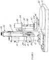
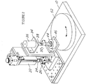
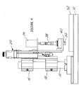
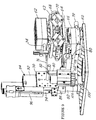
- the apparatus is also comprised of a software program to control the movement and timing of the translation stage. This apparatus is depicted in Figures 1-6 of the drawing.
- the apparatus allows a user to measure and record roughness values on multiple portions of a test specimen during the testing procedure.
- the apparatus includes a mounting device that allows the test specimen to be positioned beneath a surface profilometer with accuracy and repeatability.
- the precision mounting device also allows a test specimen to be mounted such that the plane corresponding to the face of the test specimen is parallel with the measurement path of the chisel of the profilometer.
- the base of the profilometer is typically mounted on a motorized, three-axis positioning stage, and the apparatus includes a lifting arm attached to a linear stage that may be able to be raised and lowered in response to a computer-controlled, linear actuator.
- the lifting arm allows the measuring chisel of the profilometer to come into contact with the face of the test specimen and then be raised at the conclusion of a measurement.
- the apparatus also is typically operated in accord with a software program to control the movement of the motorized stages, the movement of the lifting arm, and collection of the profilometer readings.
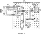
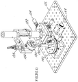
- Figures 7-11 of the drawing depict an embodiment of the apparatus.
- the apparatus enables a user to measure changes in the amount of material removed from the surface of a test specimen during the testing procedure.
- the apparatus includes a mounting device that allows the specimen to be positioned in the center of a motorized rotation stage with accuracy and repeatability.
- the apparatus is comprised of an electronic height indicator mounted on a two-axis positioning table (this positioning table may be computer controlled).
- the electronic height indicator is mounted on the two-axis positioning table such that its measurement axis is perpendicular to the plane of the two-axis table.
- the indicating rod of the electronic height indicator may be raised and lowered from and to the surface of the test specimen, respectively, by a computer-controlled, linear actuator.
- the apparatus typically operates in accord with a software program to control the movement of the stage, the movement of the electronic height indicator, and collect the height measurement readings.
- Figures 12-14 of the drawing depict an embodiment of the apparatus.
- the apparatus enables a user to measure changes in gloss on the surface of the test specimen during the testing procedure.
- the apparatus includes a mounting device that allows the specimen to be positioned over the aperture of a glossmeter with accuracy and repeatability.
- the mounting device is typically secured to a vertical slide (can be computer-controlled) that allows the face of the specimen to be lowered onto the face of the glossmeter over its aperture.
- the vertical slide is mounted to a horizontal slide (can be computer-controlled) such that the face of the specimen can be moved parallel to the face of the glossmeter.
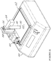
- Figure 15 of the drawing depicts an embodiment of the apparatus.
- the apparatus enables application of a constant, programmed load by a polishing instrument or tool to a test specimen while the tool is moved in a programmed manner.
- the apparatus includes a mounting device that allows the test specimen to be mounted to it with accuracy and repeatability. This mounting device allows the specimen to be removed from the apparatus and then precisely remounted when required without losing the original position setting.
- the test specimen is mounted upon a force sensing holder or mount that accurately reports force applied to the specimen.
- the precision mount is attached to a vertical slide that is controlled by a motor which can move the specimen into the pathway of a polishing instrument. Power to the motor is controlled by a microprocessor and associated electronic hardware and software.
- the apparatus allows a predetermined load to be set programmatically at any time and maintained in accord with software in the processor.
- a clamp holds a polishing device and/or tool and/or instrument over the surface of the test specimen.
- the clamp is affixed to a manual rotation table.
- the rotation table may be motorized to enable the position of the device and/or instrument to be computer-controlled. Once the specimen contacts the polishing device and/or instrument, the motorized positioning table has the ability to move the specimen beneath the polishing device and/or instrument for a preprogrammed time, distance, pattern and speed while the computer-controlled motor maintains the load on the specimen at the programmed setting.
- Figures 16-19 of the drawing depict an embodiment of this apparatus.
- the five described machines or devices may be mounted together as a test station or mounted separately. In combination, they comprise a system which accurately and with repeatability provides test data enabling the establishment of methods for evaluating performance of materials such as dental restoratives and for comparison testing the efficacy and utility of polishing materials and devices.
- specimens in the form of a disk or cylinder with a generally planar face transverse to the axis of the disk or cylinder are used in the conduct of the protocols associated with the devices described (see Figures 20A and 20B ).
- the disk is then processed to establish quantitative measurements of polishability in accord with the general flow diagram of Figure 21 using the described apparatus.
- the resultant data is highly repeatable and thus highly desired to, for example, establish or verify standards in a relevant field.
- the apparatus may be utilized to quantify polishing tool or instrument data to thereby establish utility and efficacy for purposes, for example, of comparison with standardized data.
- the system thus includes associated software to control motion components (motors and actuators) within the system.
- the software of an embodiment may typically be comprised of the following elements or equivalent controllers: a) An embedded control program, in an embodiment of the invention, developed for an 8051 microprocessor controller, written in C, b) a Graphical User Interface written in G using Active-X Controls to communicate with peripherals, and c) various data processing scripts written in Visual Basic, which parse and organize the data.
- embedded software in an embodiment of the invention consists of initialization routines including a) Programmable Counter Array Setup, b) Analog to Digital Converter Setup, c) I/O Port Setup, d) System Clock Initialization, and e) Serial Communication Setup.
- the embedded software written for this system dynamically and automatically controls the force application hardware and is interrupt driven. Thus, it waits for external or internal events to execute certain subroutines upon calling.
- the interrupt driven routines include a) RS232 communication, b) force control hysteresis, c) programmed force update routine, and d) analog to digital conversion of the force sensor signal.
- Associated software was written in the G programming language and utilizes Active-X controls to actuate the motion components of the system including all linear actuators, rotation stages, and linear stages.
- the G program also communicates with the microprocessor to set the programmed force, start/stop the force application, and call for the current programmed force for troubleshooting the software.
- the G program also provides a graphical user interface for a user to interact with the system and set testing specifications such as contact time, contact force, and number of passes.
- Final output for the roughness measurement component is processed with numerous scripts written in Visual Basic.
- a specific flow chart of the operation of the software is shown in Fig. 22
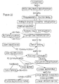
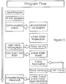
- a concept map is shown in Fig. 23 .
- Yet a further object of the invention is to provide a series of interrelated apparatus for polishing and conditioning solid materials to determine the utility and efficacy of such materials as well as to determine the utility and efficacy of instrumentation useful in the conditioning of such materials. Further, protocols associated with the interrelationship of the apparatus are disclosed to enable replication of conditions associated with the testing of materials and the polishability thereof.
- Another object of the invention is to provide transformational software which in combination with apparatus enables the preparation of samples for testing of polishability thereof and accurate and repeatable quantitative analysis of polishability and other parameters associated with such materials.
- Figures 1-19 comprise embodiments of five separate stations utilized in the practice of the method of the invention and constituting apparatus to enable the practice of multiple steps associated with the collection of data potentially useful for standardizing and uniformly characterizing materials and the polishing of such materials, for example, dental materials or restoratives.
- composite materials such as a combination of silica and bis-GMA including various additives and other formulations desirably will meet certain polishability standards as well as reflective standards and the like.
- polishability standards as well as reflective standards and the like.
- the mechanisms and protocols described provide a means to establish such characterizations in a reproducible manner.
- the various stations or apparatus are described sequentially in the order in which they are typically used.
- the first device which is described is an initial surface finish preparation apparatus and is depicted in Figures 1-6 of the drawing.
- This device is used to initially prepare a desired, roughened surface or desired rough surface of a particular material.
- the device is designed to enable the consistent replication of the uniformity of surface of specific materials, such as dental filler materials referenced above when initially implanted and roughly formed or shaped. Subsequently, modifications to the surface by a tool, such as a dental tool, can be evaluated as described hereinafter.
- the roughness of the surface is quantified. This is done using a second station or apparatus which constitutes a surface roughness measurement apparatus as illustrated in Figures 7-11 .
- a device for determination of the amount of material removed from the surface of a test specimen during any testing procedure is utilized.
- This particular device may be used at any stage in the processing of the material. It may be used to determine the amount of material removed from the initial test specimen once a base height of the specimen is established as well as the amount removed upon the completion of the series of steps used to characterize the material.
- This apparatus is identified as a height measurement apparatus and Figures 12-14 depict an embodiment thereof.
- the fifth and final apparatus in the protocol is a polishing device which enables testing of the efficacy of polishing the material using various polishing instruments or devices.
- the polishing device testing apparatus may be used not only to test the polishability of specimens, but also to test the instruments that are used for the polishing of the specimen that has been prepared for testing.
- Figures 16-19 of the drawing depict an embodiment of this particular element of the invention.
- Figures 20A and 20B The overall stages in the testing protocol using the separate devices are depicted in a flow chart as Figure 21 .
- Figure 22 illustrates the flow chart associated with the operation of software controlling one of the devices; namely, the polishing device.
- Figure 23 illustrates a functional flow chart associated with the polishing device.
- the apparatus is designed to hold a disk or cylinder specimen or sample and to polish one side of the surface of that sample.
- the objective of the apparatus is to provide an initial uniform surface finish which replicates, by way of example, a dental filling or replacement material subsequent to its initial shaping by means of a dental finishing burr or the like.
- the surface thus, has a roughness associated with the particular dental tool that has been used to roughly shape the dental filling or the like.
- the surface is in its initial form upon placement in the dental cavity.
- the apparatus includes a support base 10 having a mounting post 12 vertically extending therefrom.
- the mounting post 12 includes a guide rail 14 affixed along a vertical side thereof.
- the guide post 14 is affixed to the post 12 by means of attachment brackets 16 and 18.
- a sample or specimen support assembly 20 is slidably mounted on the post by interaction with the guide rail 14. That is, the assembly 20 includes a housing 22 slidably mounted on guide rail 14 with a rod 24 associated with a cylinder within the housing 22 to provide for slidable adjustment of the housing 22 on the rail 14 inasmuch as the rod 24 bottoms out against a stop 26 mounted at the lower end of the bracket 18.
- a manually adjustable knob 28 enables rough adjustment of the position of the housing 22 and the mechanisms attached thereto.
- a support plate 32 is attached to the housing 22 and moves vertically upwardly and downwardly in response to the movement of the housing 22.
- a first bracket 34 supports a motor 36 having a drive shaft 38 connected to a sample support 40.
- the sample support 40 is rotationally positioned within a ring bearing 42 mounted in a block 44 supported by a second or lower bracket 46 attached to the plate 32.
- the sample support 40 supports a specimen 50 adhered at its distal or lower end.
- the motor 36 is enabled to rotationally drive the shaft 38.
- the plate 32 may move upwardly and downwardly in a vertical direction to position the specimen 50 in opposition to a rotational platen 52 which may be rotationally driven either the clockwise or counterclockwise sense on the base 10.
- the speed of the platen 52 will vary depending upon the material being abraded, typically 5 to 510 rpm. However, the speed may be adjusted in any manner desired in order to test the particular material under investigation.
- the platen 52 is typically covered with a removable disk of a graded grit covered material.
- a carbide based grit may be utilized on the disk.
- Specimen 50 is positioned so that it will engage the surface of platen 52 and, more particularly, the grit material on the surface of the platen 52 in a normal or perpendicular manner.
- the specimen 50 may be adjusted in an angular fashion to provide for engagement in a non-normal manner.
- the specimen 50 is rotated about its cylindrical axis in either a clockwise or counterclockwise direction by virtue of the operation of the motor 36.
- the housing 22 may be raised and lowered to thereby raise and lower the plate 32 vertically to control the engagement of the specimen 50 with the surface of the platen 52.
- the speed and force of engagement and other characteristics associated with the initial surface finish preparation protocol may be controlled through appropriate software which controls the vertical position of the specimen 50 as well as the rotational speed and direction of the specimen 50 and/or the platen 52.
- the surface preparation finish apparatus After preparation of the specimen 50 utilizing the aforedescribed surface preparation finish apparatus, it is appropriate to measure and record the roughness of the test specimen 50 as initial reference data with respect to the surface treatment protocol. It is then used subsequently to collect surface roughness measurements after the material has been modified. These surface measurements are repeated as necessary. Thus, the surface roughness measurements are made on the sample after preparation by the initial surface roughness preparation apparatus to get a baseline reading on the control region and the region that will be tested. At this point, they will (or should) be essentially the same. Then the specimen is polished and the roughness on the control and polished (test) regions are measured again. The control readings should be the same. If not, then something is wrong (e.g., misalignment in the holder, etc.).
- a support base 60 includes a profilometer 62 which is mounted on an adjustable platform 63.
- the platform 63 is further mounted on a base 64 which, in turn, is mounted on a horizontal positioning stage 66.
- the profilometer 62 may be adjusted upwardly and downwardly in height by rotation of a control knob 68 which adjusts the linkage assembly 70.
- the horizontal positioning assembly which supports the horizontal platform 64 on the base 60 may be adjusted by turning the control knob 72 to move the assembly thereby adjusting the stage 66 in an X direction or, in other words, toward the test specimen and the assembly associated therewith as described in greater detail hereinafter.
- the profilometer 62 includes a shaft 74 and an associated profilometer stylus 76 which also move in the X direction in order for the profilometer 62 to receive input regarding the profile of the test specimen 50.
- the stage 66 further includes a motorized Y-axis positioning arrangement comprising a cylinder within a housing 78 which drives a motorized shaft 80 to thereby position the stage 66 in the Y-axis direction.
- a motorized Y-axis positioning arrangement comprising a cylinder within a housing 78 which drives a motorized shaft 80 to thereby position the stage 66 in the Y-axis direction.
- a vertical support post 82 mounted on the base 60 supports a Z-axis positioning assembly 84.
- the Z-axis position assembly 84 is slidable in the X direction in a bracket 86 mounted on the post 82.
- the Z-axis position stage further includes an arm 88 which is moveable in the Z direction.
- the arm 88 is attached to a slidable plate 90 mounted on a plate or bracket 92 attached to the post 82.
- the slidable bracket 90 moves upwardly or downwardly in response to a rod 94 associated with a cylinder within the cylinder housing 96 to thereby permit precise adjustment of the arm 88 as the plate 90 is raised or lowered in response to manual or programmatic direction.
- a further support post 100 supports a test specimen holder, clamp or collet 102 in which the test specimen 50 is mounted on the support 40 positioned and maintained in a substantially fixed position.
- the holder 102 may be rotated with respect to the post 100 by virtue of a rotational clamp mechanism 106.
- the specimen 50 which was derived from the surface finish preparation apparatus is thus mounted in the holder or clamp 102 and is attached to the same specimen support 40.
- the specimen 50 and its support 40 during the testing procedure, are maintained in the same holder throughout the various test operations. Since support 40 remains dimensionally unchanged, all data derived relates to the working of specimen 50.
- the profilometer rod 76 includes a stylus at its outer end which is guided over the top, roughened surface of the specimen 50.
- Data is acquired by the profilometer 62 to provide a baseline of information regarding the surface roughness and character of the surface of the specimen 50 before final polishing.
- Data may also be acquired once the specimen 50 is polished. Further, data may be acquired for roughened and polished sections of the planar surface of the specimen such as designated in Figure 20A . Again, the operation of the various motorized elements of the device may be computer controlled for precise measurement and ultimate recording of data.
- FIGS 12-14 illustrate the height measurement apparatus.
- the height measurement apparatus enables a measurement of the amount of material removed from the surface of the specimen 50 retained in the support, holder or mounting member 40 at any stage in the operation of the test procedure.
- the height measurement apparatus includes a base 120 with a support post 122 mounted on an XY positioning stage.
- the XY positioning stage includes an X-axis adjustment mechanism 124 and a Y-axis adjustment mechanism 126.
- a support bracket 128 is affixed to the post and supports an electronic height indicator 130 which includes an output shaft 132 is operated by a linear actuator 134 mounted to the bracket 128.
- the linear actuator 134 is used to raise and lower the probe of the shaft 132 of the electronic height indicator from and to, respectively, the surface of the specimen 50.
- a probe 136 extends from the height indicator 130 and impacts upon the surface of the specimen 150.
- the length of the composite specimen 50 and its support 40 are retained upon the planar surface 138 of the specimen holder assembly 140.
- the specimen holder assembly 140 includes a rotational platform 142 mounted on a motorized positioning stage 144 supported on the base 120. In this manner the height of the specimen (indicating the amount of material removed) may be determined over the entire surface of the specimen. Positioning of the height probe with the X and Y axis positioning stage enables gross adjustment and the positioning stage assembly 144 enables rotational adjustment. The data secured from the device may then be stored for graphing and computer analysis.
- the gloss measurement apparatus is depicted in Figure 15 .
- the gloss measurement device employs a gloss meter device 150 with a special support assembly for the test specimen 50 including the specimen pylon support or rod 40.
- the rod 40 is supported over an aperture 152 of the gloss meter 150 by the positioning assembly which includes a holder 154 for the rod or support 40 mounted on a vertical positioning slide 156 affixed to a bracket 158 mounted on a horizontal positioning slide 160.
- the assembly is mounted on a plate or platen 162 on the top face of the gloss meter. Standard gloss meter readings may thus be obtained with respect to polished and unpolished and partially polished specimen materials. Again, computer storage of the readout data is enabled.
- FIGS 16-19 depict the above-identified apparatus.
- the apparatus includes a support base 180.
- a first vertical support post 182 supports a clamp assembly 184 at the top of the post 182.
- the clamp assembly includes an adjustable instrument support device 186 such as a device to support a dental instrument 190 or other such device used to modify the specimen surface.
- the instrument support device 186 includes a clamping member 188 which is designed to hold a dental instrument 190.
- the polishing device 190 includes a polishing burr or pad 192. The angle of attack of the pad 192 may be adjusted rotationally by operation of the knob 194 for the support post 186. Thus, axial adjustment about the axis 196 may be provided for the polishing instrument 190 as well as axial adjustment.
- the apparatus further includes a second support post 198 with first and second spaced clamps 200 and 202 which, in turn, support a slidable test specimen holder 204 which is designed to move in a Z or vertical axis direction in response to the operation of a control motor 206 through the linkage 208.
- the test specimen holder 204 thus holds the test specimen 50 and its mounting rod or support 40.
- the vertical positioning clamp 184 may then be adjusted downwardly so that the polishing face of the polishing device 192 may be positioned against or over the top surface of the specimen 50. A programmed movement of the test specimen holder may then be utilized to engage the test specimen against the polishing instrument.
- the post 198 is mounted on a horizontally moveable platform 199 which moves in the Y direction in response to actuation of a shaft or rod 201 responsive to a motorized horizontal positioning cylinder 203. Movement in the Y axial direction may be included by modification of the platform 199 to move in Y or XY directions.
- the specimen 50 may be subjected to engagement by the polishing pad or the like over its surface in the X direction at a controlled load.
- the instrument 190 may also be adjusted with respect to its angle of inclination.
- the knob 194 may be adjusted to change the attitude of the instrument 190 and the knob 194 may also be adjusted in order to axially move the instrument 192 along the axis 196.
- the operation of the motor 206 as well as the horizontal positioning stage 203 may be computer controlled.
- Figure 20A illustrates the top surface of a disk 50 which has been subjected to working or measurements by various apparatus when conducting the test protocols described hereinafter.
- Figure 20B illustrates the side view of the polished disk. Initially, the roughness of the surface is caused using the surface finish preparation apparatus. The roughness is then quantified by the surface roughness measurement apparatus. Height measurement indicates the amount of material removed by the roughness operation. Gloss may be measured subsequently or prior thereto. Finally, the polishing device is tested using the described machine and the polished region viewed or measured by means of the profilometer or gloss measurement apparatus with the data obtained compared to the control (rough) portion of the specimen that has not been polished.
- a control region 220 comprises the region 220 of the surface of the disk 50 which has been conditioned by the initial surface preparation apparatus.
- the polished region 222 is the region of the surface of the disk initially conditioned by the initial surface preparation apparatus and then further conditioned by the polishing device testing apparatus.
- Figure 21 illustrates the steps that would normally be conducted using the apparatus. Initially, a sample 50 is prepared and mounted on a support or rod 40. Initial surface preparation is performed using the initial surface preparation apparatus. Subsequently, roughness, height, and gloss of the specimen surface is established on two regions of the surface, which shall serve as the control and test region. Polishing is then performed on the test region. The roughness, height, and gloss are then measured in the same two regions at the same places on those regions and the resulting data for all measurements is processed. The multiple steps of polishing followed by measurements of roughness, height and gloss in the control and test regions can be repeated as desired.
- Figure 22 is a flow chart showing the multiple steps that may be utilized for control of the polishing apparatus.
- the system is initially started and initialized. Importantly, a subsequent step is timing of the events.
- the force of the polishing instrument against the specimen surface is programmed and an initial test run is then caused to occur. During initial test run, the time is controlled, the force is controlled and the linear motion in the X direction is controlled. All the data is gathered for recordal and graphing.
- Figure 23 is a simplified flow chart associated with the operation of the polishing testing device. It represents a flow of the various steps associated with Figure 22 .
- Two dental composite materials shall be used along with a dental polishing instrument in this study.
- Heliomolar agglomerated microfill composite, Ivoclar Vivadent, Inc.
- Esthet-X HD hybrid, mini-fill, Dentsply Caulk, Inc.
- PDQ2 polishing instrument Item# P3138, Axis Dental, Inc.
- any dental composite material and polishing instrument combination can be used with the described system.
- Teflon molds for the preparation of cylindrical specimens, 4 mm thick x 15 mm in diameter. Note that the molds shall be vented such that when pressure is applied to the molds excess material can flow out the vents.
- Film transparent to the activating radiation, e.g., polyester, 50 ⁇ 30 ⁇ m thick.
- the Optilux 501 (Kerr Corporation) dental curing unit, with a 13 mm tip, shall be used as the external energy source.
- the measured irradiance of the external energy source shall be above 300 mW/cm 2 as measured according to ISO 10650 "Dentistry - Powered Polymerization Activators.”
- Garolite grade G-10, 15 mm in diameter, to be used to mount the composite material in the various apparatuses of the system.
- Cyanoacrylate glue e.g., Loctite 414, Loctite, Corp.
- primer e.g., Loctite 7471 Primer, Loctite, Corp.
- Surface roughness measurement apparatus e.g., Surtronic 3+, Taylor Hobson, Inc.
- the settings for the surface profilometer were the following: 2.5 mm traverse length, cutoff value of 0.25 mm, and traverse speed of 1 mm/s.
- the electronic height indicator e.g., Mitutoyo 543 electronic indicator
- the electronic height indicator was accurate to 0.001 mm.
- Gloss measurement apparatus e.g., Novo-Curve Glossmeter, Rhopoint Instrumentation LTD, East Canal, UK.
- the glossmeter had a 60° geometry.
- Figure 24 shows the surface roughness and gloss measurement results for the PDQ2 polishing instrument used on the two composites in this study.
- each data point represents the average Ra value of five traces of the profilometer.
- the data from the test region and from the control region is plotted.
- each data point represents the average gloss of three readings of the glossmeter.
- the data from the test region and from the control region is plotted.
- test protocols exhibited excellent consistency of quantitative data including time dependent data. As a consequence, the repeatability of test results enables one to quantitatively establish product parameters that enable creation of usable standards.
Landscapes
- Physics & Mathematics (AREA)
- General Physics & Mathematics (AREA)
- Sampling And Sample Adjustment (AREA)
Claims (7)
- Appareil pour tester des matériaux de polissage et des états de surface polis de matériaux composites comprenant :A) un appareil d'abrasion de surface pour conférer une rugosité à la surface d'un échantillon comprenant :une base (10) ;une platine rotative (52) avec une surface en matériau abrasif sur ladite platine ;un support d'échantillon (20) monté sur ladite base, ledit support comprenant un support mobile globalement transversal par rapport à la platine, et un porte-échantillon supporté par le support, ledit support comprenant en outre un lecteur de support pour entraîner en rotation l'échantillon dans le porte-échantillon, de sorte que ledit échantillon est mobile en contact avec ladite surface de matériau abrasif :B) un appareil de test de dispositif de polissage pour appliquer un dispositif de polissage à l'échantillon comprenant :un support (198) ;une platine (199) sur ledit support ayant au moins un mouvement de degré le long d'un premier axe ;un dispositif de confinement d'échantillon (204) monté sur la platine ;un mécanisme d'entraînement (206) monté sur le plateau pour entraîner le dispositif de confinement dans une direction généralement normale au premier axe ;un support (186) pour un dispositif de polissage comprenant un mécanisme d'alignement pour orienter le dispositif de polissage contre un échantillon dans le dispositif de confinement ; etsystème de commande programmable pour commander le mouvement du plateau et du dispositif de confinement ; etC) un appareil de mesure de rugosité de surface pour mesurer la rugosité de la surface comprenant :une base (60)un profilomètre (62) monté sur un socle sur ladite base, ledit socle réglable dans un plan XY et sur l'élévation de l'axe Z, ledit profilomètre comprenant un capteur de stylet pour engager la surface de l'échantillon et mesurer la rugosité lors d'un mouvement dans un plan XY.
- Un appareil selon la revendication 1, comprenant en outre :D) un appareil selon la revendication 1, comprenant en outre :une base (120) ;un support d'échantillon sur la base ;un poteau de support (122) ;un dispositif transducteur (130) monté sur le montant de support et un capteur (136) pour mettre en prise la surface de l'échantillon et entraîner le transducteur en réponse à la hauteur de l'échantillon.
- L'appareil des revendications 1 ou 2, dans lequel la platine de l'appareil d'essai du dispositif de polissage a deux degrés de liberté perpendiculaires à la direction axiale de confinement.
- L'appareil selon l'une quelconque des revendications 1 à 3, dans lequel ledit système de commande contrôle la charge et la durée d'engagement de l'échantillon et du dispositif de polissage.
- Un procédé d'essai de normes pour la détermination des caractéristiques de polissage d'une surface d'éprouvette solide exécutant un matériau en utilisant l'appareil selon l'une quelconque des revendications précédentes, comprenant les étapes consistant à :(a) conférer une rugosité à ladite surface dudit échantillon en utilisant ledit appareil d'abrasion de surface ;(b) mesurer la rugosité de la surface avec l'appareil de mesure de la rugosité de surface ;(c) appliquer un dispositif de polissage à seulement une partie de la surface rugueuse pour polir ladite partie en utilisant l'appareil de test du dispositif de polissage ; et(d) mesurer un paramètre de la partie polie de la surface choisie dans le groupe constitué de la rugosité et de la brillance du matériau en utilisant l'appareil de mesure de la rugosité de surface.
- Le procédé selon la revendication 5, lorsque l'appareil de la revendication 2 est utilisé, comprenant en outre l'étape de mesure de la quantité de matériau retiré de ladite surface dans l'étape de rugosité de transmission en utilisant l'appareil de quantification.
- Le procédé selon les revendications 5 ou 6, comprenant en outre l'étape consistant à mesurer le brillant de la surface après au moins l'étape de rugosité ou l'étape de polissage, ou les deux.
Applications Claiming Priority (2)
| Application Number | Priority Date | Filing Date | Title |
|---|---|---|---|
| US10132008P | 2008-09-30 | 2008-09-30 | |
| PCT/US2009/059094 WO2010039878A1 (fr) | 2008-09-30 | 2009-09-30 | Appareil et procédés destinés à tester la capacité de matériaux à être polis |
Publications (3)
| Publication Number | Publication Date |
|---|---|
| EP2334254A1 EP2334254A1 (fr) | 2011-06-22 |
| EP2334254A4 EP2334254A4 (fr) | 2014-12-31 |
| EP2334254B1 true EP2334254B1 (fr) | 2018-03-28 |
Family
ID=42057969
Family Applications (1)
| Application Number | Title | Priority Date | Filing Date |
|---|---|---|---|
| EP09818464.1A Not-in-force EP2334254B1 (fr) | 2008-09-30 | 2009-09-30 | Appareil et procédés destinés à tester la polissabilité de matériaux |
Country Status (4)
| Country | Link |
|---|---|
| US (2) | US8398454B2 (fr) |
| EP (1) | EP2334254B1 (fr) |
| CA (1) | CA2738811C (fr) |
| WO (1) | WO2010039878A1 (fr) |
Cited By (1)
| Publication number | Priority date | Publication date | Assignee | Title |
|---|---|---|---|---|
| WO2020057652A1 (fr) * | 2018-09-21 | 2020-03-26 | 苏州海得威视信息技术有限公司 | Dispositif multidirectionnel utilisant une identification visuelle pour des produits de moulage par injection électronique de précision |
Families Citing this family (10)
| Publication number | Priority date | Publication date | Assignee | Title |
|---|---|---|---|---|
| CN103252720B (zh) * | 2013-05-10 | 2015-12-23 | 南通星维油泵油嘴有限公司 | 磨加工针阀体中孔的plc控制器及其自动送料机构的控制方法 |
| CN105598827B (zh) * | 2016-01-05 | 2018-05-22 | 天津华海清科机电科技有限公司 | 化学机械抛光机 |
| KR101766142B1 (ko) | 2016-05-18 | 2017-08-10 | 인하대학교 산학협력단 | 핸드피스 버의 절삭 성능 평가 시스템 및 평가방법 |
| CN106736883A (zh) * | 2017-01-03 | 2017-05-31 | 佛山市三水区琪昌机械设备有限公司 | 一种瓷砖抛光方法及其终端 |
| CN108724002B (zh) * | 2018-05-31 | 2020-04-21 | 上海理工大学 | 平面磨削工件表面粗糙度计算方法 |
| US11293743B2 (en) * | 2018-12-20 | 2022-04-05 | Ametek, Inc. | Texture analyzer |
| CN109799138B (zh) * | 2019-02-20 | 2023-09-22 | 中国工程物理研究院激光聚变研究中心 | 抛光盘弹性模量和蠕变特性在位测量装置及测量方法 |
| CN112157561B (zh) * | 2020-08-14 | 2022-03-29 | 大连理工大学 | 一种具有盘面在位测量与修整功能的抛光机 |
| JP7655246B2 (ja) * | 2022-02-25 | 2025-04-02 | 株式会社デンソー | 測定装置およびレーザ加工装置 |
| CN116222490B (zh) * | 2023-05-09 | 2023-07-14 | 深圳市利盛五金螺丝模具有限公司 | 一种模具检测装置 |
Family Cites Families (8)
| Publication number | Priority date | Publication date | Assignee | Title |
|---|---|---|---|---|
| DE2405578C3 (de) * | 1974-02-06 | 1988-07-28 | Kulzer & Co Gmbh, 6380 Bad Homburg | Polymerisierbares Bindemittel enthaltender Dentalwerkstoff und seine Verwendung für Zähne und Zahnersatzteile |
| DE3716413A1 (de) * | 1987-05-15 | 1988-12-01 | Kaltenbach & Voigt | Vorrichtung zum schleifen zahnaerztlicher oder zahntechnischer werkstuecke |
| FR2620223B1 (fr) * | 1987-09-09 | 1994-03-25 | Institut Superieur Etat Surface | Procede pour faire glisser un support mobile sur une surface de reference et dispositif associe |
| CH686657A5 (de) | 1991-11-17 | 1996-05-31 | Liconic Ag | Verfahren zur Herstellung eines partiellen Ersatzes eines Zahnes und Einrichtung zur Durchfuehrung des Verfahrens. |
| SE509005C2 (sv) * | 1997-02-24 | 1998-11-23 | Dentronic Ab | Förfarande och arrangemang för beröringsfri inmätning av den tre-dimensionella formen hos detala objekt |
| JPH10323353A (ja) | 1997-05-26 | 1998-12-08 | G C:Kk | 歯科用レジン材料及びその作製方法 |
| DE502005006910D1 (de) * | 2004-11-25 | 2009-04-30 | Heinrich Steger | Kopierfräseinrichtung zur herstellung von insbesondere zahntechnischen werkstücken |
| JP4815226B2 (ja) * | 2006-02-01 | 2011-11-16 | マニー株式会社 | 歯科用軸付砥石及びその製造方法 |
-
2009
- 2009-09-30 CA CA2738811A patent/CA2738811C/fr not_active Expired - Fee Related
- 2009-09-30 EP EP09818464.1A patent/EP2334254B1/fr not_active Not-in-force
- 2009-09-30 WO PCT/US2009/059094 patent/WO2010039878A1/fr not_active Ceased
- 2009-09-30 US US12/571,077 patent/US8398454B2/en not_active Expired - Fee Related
-
2013
- 2013-03-04 US US13/783,724 patent/US8657645B2/en not_active Expired - Fee Related
Cited By (1)
| Publication number | Priority date | Publication date | Assignee | Title |
|---|---|---|---|---|
| WO2020057652A1 (fr) * | 2018-09-21 | 2020-03-26 | 苏州海得威视信息技术有限公司 | Dispositif multidirectionnel utilisant une identification visuelle pour des produits de moulage par injection électronique de précision |
Also Published As
| Publication number | Publication date |
|---|---|
| US20130178135A1 (en) | 2013-07-11 |
| CA2738811C (fr) | 2017-03-14 |
| WO2010039878A1 (fr) | 2010-04-08 |
| EP2334254A4 (fr) | 2014-12-31 |
| US8657645B2 (en) | 2014-02-25 |
| US8398454B2 (en) | 2013-03-19 |
| US20100081362A1 (en) | 2010-04-01 |
| CA2738811A1 (fr) | 2010-04-08 |
| EP2334254A1 (fr) | 2011-06-22 |
Similar Documents
| Publication | Publication Date | Title |
|---|---|---|
| EP2334254B1 (fr) | Appareil et procédés destinés à tester la polissabilité de matériaux | |
| Kim et al. | Effects of thermal and mechanical cycling on the mechanical strength and surface properties of dental CAD-CAM restorative materials | |
| Kim et al. | Polymerization shrinkage-strain kinetics of temporary crown and bridge materials | |
| Lu et al. | Probing the origins and control of shrinkage stress in dental resin-composites: I. Shrinkage stress characterization technique | |
| Magdy et al. | Evaluation of surface roughness of different direct resin-based composites | |
| JP2003531469A (ja) | 広がり抵抗プロファイリングシステム | |
| De Souza et al. | Flexural strength and crystalline stability of a monolithic translucent zirconia subjected to grinding, polishing and thermal challenges | |
| Chung et al. | Effects of surface finish on indentation modulus and hardness of dental composite restoratives | |
| Harper et al. | The use of shimstock to assess occlusal contacts: a laboratory study. | |
| Walia et al. | Comparative evaluation of surface roughness of posterior primary zirconia crowns | |
| Mayinger et al. | Impact of high-speed sintering of three-unit 3Y-TZP and 4Y-TZP fixed dental prostheses on fracture load with and without artificial aging | |
| Al-Johani et al. | Effect of repeated firing on the topographical, optical, and mechanical properties of fully crystallized lithium silicate-based ceramics | |
| JPS63212348A (ja) | 歯科用計測装置 | |
| Gan et al. | Effect of airborne-particle abrasion with a novel spherical abrasive on the zirconia surface | |
| Brandeburski et al. | Quantitative and qualitative analyses of ceramic chipping | |
| CN215677943U (zh) | 一种基于压痕深度的洛氏硬度计检定装置 | |
| CN110186797B (zh) | 一种口腔正畸矫正方弓丝摩擦磨损实验装置及其实验方法 | |
| Onwubu et al. | The effect of colloidal silica and diamond suspensions on the surface roughness of automatically finished heat-polymerized acrylic resin | |
| Lubauer et al. | A split-Chevron-Notched-Beam sandwich specimen for fracture toughness testing of bonded interfaces | |
| Bayraktar et al. | Evaluation of correlation between wear resistance and microhardness of resin based CAD/CAM blocks | |
| Bayar et al. | In-vitro Testing Methods For The Evaluation Of The Mechanical Properties Of Composite Resins | |
| Valcke et al. | The porosity and roughness of four direct filling resins | |
| CN100348967C (zh) | 二维自由度口腔材料磨削修复体外模拟试验机 | |
| Heintze et al. | Automatic Gap Detection at Restoration Margins with an Optical Sensor In Vitro. | |
| CN222144691U (zh) | 一种硬质合金检测装置 |
Legal Events
| Date | Code | Title | Description |
|---|---|---|---|
| PUAI | Public reference made under article 153(3) epc to a published international application that has entered the european phase |
Free format text: ORIGINAL CODE: 0009012 |
|
| 17P | Request for examination filed |
Effective date: 20110427 |
|
| AK | Designated contracting states |
Kind code of ref document: A1 Designated state(s): AT BE BG CH CY CZ DE DK EE ES FI FR GB GR HR HU IE IS IT LI LT LU LV MC MK MT NL NO PL PT RO SE SI SK SM TR |
|
| AX | Request for extension of the european patent |
Extension state: AL BA RS |
|
| DAX | Request for extension of the european patent (deleted) | ||
| A4 | Supplementary search report drawn up and despatched |
Effective date: 20141127 |
|
| RIC1 | Information provided on ipc code assigned before grant |
Ipc: G01B 21/30 20060101ALI20141121BHEP Ipc: A61C 17/16 20060101AFI20141121BHEP Ipc: G01B 5/28 20060101ALI20141121BHEP |
|
| RAP1 | Party data changed (applicant data changed or rights of an application transferred) |
Owner name: AMERICAN DENTAL ASSOCIATION |
|
| RIN1 | Information on inventor provided before grant (corrected) |
Inventor name: SIROVSKAYA, OLGA Inventor name: MEGREMIS, SPIRO Inventor name: NJEGOVAN, NIKOLA Inventor name: SHEPELAK, HANK |
|
| STAA | Information on the status of an ep patent application or granted ep patent |
Free format text: STATUS: EXAMINATION IS IN PROGRESS |
|
| 17Q | First examination report despatched |
Effective date: 20170324 |
|
| REG | Reference to a national code |
Ref country code: DE Ref legal event code: R079 Ref document number: 602009051540 Country of ref document: DE Free format text: PREVIOUS MAIN CLASS: A61C0017160000 Ipc: G01B0005280000 |
|
| GRAP | Despatch of communication of intention to grant a patent |
Free format text: ORIGINAL CODE: EPIDOSNIGR1 |
|
| STAA | Information on the status of an ep patent application or granted ep patent |
Free format text: STATUS: GRANT OF PATENT IS INTENDED |
|
| RIC1 | Information provided on ipc code assigned before grant |
Ipc: G01B 21/30 20060101ALI20171002BHEP Ipc: G01B 5/28 20060101AFI20171002BHEP Ipc: A61C 17/16 20060101ALI20171002BHEP |
|
| INTG | Intention to grant announced |
Effective date: 20171020 |
|
| GRAS | Grant fee paid |
Free format text: ORIGINAL CODE: EPIDOSNIGR3 |
|
| GRAA | (expected) grant |
Free format text: ORIGINAL CODE: 0009210 |
|
| STAA | Information on the status of an ep patent application or granted ep patent |
Free format text: STATUS: THE PATENT HAS BEEN GRANTED |
|
| AK | Designated contracting states |
Kind code of ref document: B1 Designated state(s): AT BE BG CH CY CZ DE DK EE ES FI FR GB GR HR HU IE IS IT LI LT LU LV MC MK MT NL NO PL PT RO SE SI SK SM TR |
|
| REG | Reference to a national code |
Ref country code: GB Ref legal event code: FG4D |
|
| REG | Reference to a national code |
Ref country code: CH Ref legal event code: EP |
|
| REG | Reference to a national code |
Ref country code: AT Ref legal event code: REF Ref document number: 983837 Country of ref document: AT Kind code of ref document: T Effective date: 20180415 |
|
| REG | Reference to a national code |
Ref country code: IE Ref legal event code: FG4D |
|
| REG | Reference to a national code |
Ref country code: DE Ref legal event code: R096 Ref document number: 602009051540 Country of ref document: DE |
|
| PG25 | Lapsed in a contracting state [announced via postgrant information from national office to epo] |
Ref country code: NO Free format text: LAPSE BECAUSE OF FAILURE TO SUBMIT A TRANSLATION OF THE DESCRIPTION OR TO PAY THE FEE WITHIN THE PRESCRIBED TIME-LIMIT Effective date: 20180628 Ref country code: FI Free format text: LAPSE BECAUSE OF FAILURE TO SUBMIT A TRANSLATION OF THE DESCRIPTION OR TO PAY THE FEE WITHIN THE PRESCRIBED TIME-LIMIT Effective date: 20180328 Ref country code: LT Free format text: LAPSE BECAUSE OF FAILURE TO SUBMIT A TRANSLATION OF THE DESCRIPTION OR TO PAY THE FEE WITHIN THE PRESCRIBED TIME-LIMIT Effective date: 20180328 Ref country code: HR Free format text: LAPSE BECAUSE OF FAILURE TO SUBMIT A TRANSLATION OF THE DESCRIPTION OR TO PAY THE FEE WITHIN THE PRESCRIBED TIME-LIMIT Effective date: 20180328 |
|
| REG | Reference to a national code |
Ref country code: NL Ref legal event code: MP Effective date: 20180328 |
|
| REG | Reference to a national code |
Ref country code: LT Ref legal event code: MG4D |
|
| PG25 | Lapsed in a contracting state [announced via postgrant information from national office to epo] |
Ref country code: GR Free format text: LAPSE BECAUSE OF FAILURE TO SUBMIT A TRANSLATION OF THE DESCRIPTION OR TO PAY THE FEE WITHIN THE PRESCRIBED TIME-LIMIT Effective date: 20180629 Ref country code: BG Free format text: LAPSE BECAUSE OF FAILURE TO SUBMIT A TRANSLATION OF THE DESCRIPTION OR TO PAY THE FEE WITHIN THE PRESCRIBED TIME-LIMIT Effective date: 20180628 Ref country code: LV Free format text: LAPSE BECAUSE OF FAILURE TO SUBMIT A TRANSLATION OF THE DESCRIPTION OR TO PAY THE FEE WITHIN THE PRESCRIBED TIME-LIMIT Effective date: 20180328 Ref country code: SE Free format text: LAPSE BECAUSE OF FAILURE TO SUBMIT A TRANSLATION OF THE DESCRIPTION OR TO PAY THE FEE WITHIN THE PRESCRIBED TIME-LIMIT Effective date: 20180328 |
|
| REG | Reference to a national code |
Ref country code: FR Ref legal event code: PLFP Year of fee payment: 10 |
|
| PG25 | Lapsed in a contracting state [announced via postgrant information from national office to epo] |
Ref country code: PL Free format text: LAPSE BECAUSE OF FAILURE TO SUBMIT A TRANSLATION OF THE DESCRIPTION OR TO PAY THE FEE WITHIN THE PRESCRIBED TIME-LIMIT Effective date: 20180328 Ref country code: EE Free format text: LAPSE BECAUSE OF FAILURE TO SUBMIT A TRANSLATION OF THE DESCRIPTION OR TO PAY THE FEE WITHIN THE PRESCRIBED TIME-LIMIT Effective date: 20180328 Ref country code: ES Free format text: LAPSE BECAUSE OF FAILURE TO SUBMIT A TRANSLATION OF THE DESCRIPTION OR TO PAY THE FEE WITHIN THE PRESCRIBED TIME-LIMIT Effective date: 20180328 Ref country code: RO Free format text: LAPSE BECAUSE OF FAILURE TO SUBMIT A TRANSLATION OF THE DESCRIPTION OR TO PAY THE FEE WITHIN THE PRESCRIBED TIME-LIMIT Effective date: 20180328 Ref country code: NL Free format text: LAPSE BECAUSE OF FAILURE TO SUBMIT A TRANSLATION OF THE DESCRIPTION OR TO PAY THE FEE WITHIN THE PRESCRIBED TIME-LIMIT Effective date: 20180328 Ref country code: IT Free format text: LAPSE BECAUSE OF FAILURE TO SUBMIT A TRANSLATION OF THE DESCRIPTION OR TO PAY THE FEE WITHIN THE PRESCRIBED TIME-LIMIT Effective date: 20180328 |
|
| PG25 | Lapsed in a contracting state [announced via postgrant information from national office to epo] |
Ref country code: SK Free format text: LAPSE BECAUSE OF FAILURE TO SUBMIT A TRANSLATION OF THE DESCRIPTION OR TO PAY THE FEE WITHIN THE PRESCRIBED TIME-LIMIT Effective date: 20180328 Ref country code: SM Free format text: LAPSE BECAUSE OF FAILURE TO SUBMIT A TRANSLATION OF THE DESCRIPTION OR TO PAY THE FEE WITHIN THE PRESCRIBED TIME-LIMIT Effective date: 20180328 Ref country code: CZ Free format text: LAPSE BECAUSE OF FAILURE TO SUBMIT A TRANSLATION OF THE DESCRIPTION OR TO PAY THE FEE WITHIN THE PRESCRIBED TIME-LIMIT Effective date: 20180328 |
|
| REG | Reference to a national code |
Ref country code: AT Ref legal event code: MK05 Ref document number: 983837 Country of ref document: AT Kind code of ref document: T Effective date: 20180328 |
|
| PG25 | Lapsed in a contracting state [announced via postgrant information from national office to epo] |
Ref country code: PT Free format text: LAPSE BECAUSE OF FAILURE TO SUBMIT A TRANSLATION OF THE DESCRIPTION OR TO PAY THE FEE WITHIN THE PRESCRIBED TIME-LIMIT Effective date: 20180730 |
|
| REG | Reference to a national code |
Ref country code: DE Ref legal event code: R097 Ref document number: 602009051540 Country of ref document: DE |
|
| PG25 | Lapsed in a contracting state [announced via postgrant information from national office to epo] |
Ref country code: DK Free format text: LAPSE BECAUSE OF FAILURE TO SUBMIT A TRANSLATION OF THE DESCRIPTION OR TO PAY THE FEE WITHIN THE PRESCRIBED TIME-LIMIT Effective date: 20180328 Ref country code: AT Free format text: LAPSE BECAUSE OF FAILURE TO SUBMIT A TRANSLATION OF THE DESCRIPTION OR TO PAY THE FEE WITHIN THE PRESCRIBED TIME-LIMIT Effective date: 20180328 |
|
| PLBE | No opposition filed within time limit |
Free format text: ORIGINAL CODE: 0009261 |
|
| STAA | Information on the status of an ep patent application or granted ep patent |
Free format text: STATUS: NO OPPOSITION FILED WITHIN TIME LIMIT |
|
| 26N | No opposition filed |
Effective date: 20190103 |
|
| PG25 | Lapsed in a contracting state [announced via postgrant information from national office to epo] |
Ref country code: MC Free format text: LAPSE BECAUSE OF FAILURE TO SUBMIT A TRANSLATION OF THE DESCRIPTION OR TO PAY THE FEE WITHIN THE PRESCRIBED TIME-LIMIT Effective date: 20180328 |
|
| REG | Reference to a national code |
Ref country code: CH Ref legal event code: PL |
|
| PG25 | Lapsed in a contracting state [announced via postgrant information from national office to epo] |
Ref country code: SI Free format text: LAPSE BECAUSE OF FAILURE TO SUBMIT A TRANSLATION OF THE DESCRIPTION OR TO PAY THE FEE WITHIN THE PRESCRIBED TIME-LIMIT Effective date: 20180328 |
|
| REG | Reference to a national code |
Ref country code: BE Ref legal event code: MM Effective date: 20180930 |
|
| REG | Reference to a national code |
Ref country code: IE Ref legal event code: MM4A |
|
| PG25 | Lapsed in a contracting state [announced via postgrant information from national office to epo] |
Ref country code: LU Free format text: LAPSE BECAUSE OF NON-PAYMENT OF DUE FEES Effective date: 20180930 |
|
| PG25 | Lapsed in a contracting state [announced via postgrant information from national office to epo] |
Ref country code: IE Free format text: LAPSE BECAUSE OF NON-PAYMENT OF DUE FEES Effective date: 20180930 |
|
| PG25 | Lapsed in a contracting state [announced via postgrant information from national office to epo] |
Ref country code: LI Free format text: LAPSE BECAUSE OF NON-PAYMENT OF DUE FEES Effective date: 20180930 Ref country code: CH Free format text: LAPSE BECAUSE OF NON-PAYMENT OF DUE FEES Effective date: 20180930 Ref country code: BE Free format text: LAPSE BECAUSE OF NON-PAYMENT OF DUE FEES Effective date: 20180930 |
|
| PG25 | Lapsed in a contracting state [announced via postgrant information from national office to epo] |
Ref country code: MT Free format text: LAPSE BECAUSE OF NON-PAYMENT OF DUE FEES Effective date: 20180930 |
|
| PG25 | Lapsed in a contracting state [announced via postgrant information from national office to epo] |
Ref country code: TR Free format text: LAPSE BECAUSE OF FAILURE TO SUBMIT A TRANSLATION OF THE DESCRIPTION OR TO PAY THE FEE WITHIN THE PRESCRIBED TIME-LIMIT Effective date: 20180328 |
|
| PG25 | Lapsed in a contracting state [announced via postgrant information from national office to epo] |
Ref country code: HU Free format text: LAPSE BECAUSE OF FAILURE TO SUBMIT A TRANSLATION OF THE DESCRIPTION OR TO PAY THE FEE WITHIN THE PRESCRIBED TIME-LIMIT; INVALID AB INITIO Effective date: 20090930 |
|
| PG25 | Lapsed in a contracting state [announced via postgrant information from national office to epo] |
Ref country code: CY Free format text: LAPSE BECAUSE OF FAILURE TO SUBMIT A TRANSLATION OF THE DESCRIPTION OR TO PAY THE FEE WITHIN THE PRESCRIBED TIME-LIMIT Effective date: 20180328 Ref country code: MK Free format text: LAPSE BECAUSE OF NON-PAYMENT OF DUE FEES Effective date: 20180328 |
|
| PG25 | Lapsed in a contracting state [announced via postgrant information from national office to epo] |
Ref country code: IS Free format text: LAPSE BECAUSE OF FAILURE TO SUBMIT A TRANSLATION OF THE DESCRIPTION OR TO PAY THE FEE WITHIN THE PRESCRIBED TIME-LIMIT Effective date: 20180728 |
|
| REG | Reference to a national code |
Ref country code: DE Ref legal event code: R082 Ref document number: 602009051540 Country of ref document: DE Representative=s name: HL KEMPNER PATENTANWALT, RECHTSANWALT, SOLICIT, DE |
|
| PGFP | Annual fee paid to national office [announced via postgrant information from national office to epo] |
Ref country code: FR Payment date: 20210928 Year of fee payment: 13 |
|
| PGFP | Annual fee paid to national office [announced via postgrant information from national office to epo] |
Ref country code: GB Payment date: 20210927 Year of fee payment: 13 Ref country code: DE Payment date: 20210929 Year of fee payment: 13 |
|
| REG | Reference to a national code |
Ref country code: DE Ref legal event code: R119 Ref document number: 602009051540 Country of ref document: DE |
|
| GBPC | Gb: european patent ceased through non-payment of renewal fee |
Effective date: 20220930 |
|
| PG25 | Lapsed in a contracting state [announced via postgrant information from national office to epo] |
Ref country code: FR Free format text: LAPSE BECAUSE OF NON-PAYMENT OF DUE FEES Effective date: 20220930 Ref country code: DE Free format text: LAPSE BECAUSE OF NON-PAYMENT OF DUE FEES Effective date: 20230401 |
|
| PG25 | Lapsed in a contracting state [announced via postgrant information from national office to epo] |
Ref country code: GB Free format text: LAPSE BECAUSE OF NON-PAYMENT OF DUE FEES Effective date: 20220930 |