EP2334539B1 - Strukturverbindung für einen nutzfahrzeugrahmen und mit einer strukturverbindung hergestellter rahmen - Google Patents
Strukturverbindung für einen nutzfahrzeugrahmen und mit einer strukturverbindung hergestellter rahmen Download PDFInfo
- Publication number
- EP2334539B1 EP2334539B1 EP08815920.7A EP08815920A EP2334539B1 EP 2334539 B1 EP2334539 B1 EP 2334539B1 EP 08815920 A EP08815920 A EP 08815920A EP 2334539 B1 EP2334539 B1 EP 2334539B1
- Authority
- EP
- European Patent Office
- Prior art keywords
- frame member
- frame
- interface
- contoured
- joint
- Prior art date
- Legal status (The legal status is an assumption and is not a legal conclusion. Google has not performed a legal analysis and makes no representation as to the accuracy of the status listed.)
- Not-in-force
Links
- 230000000295 complement effect Effects 0.000 claims description 7
- 239000000463 material Substances 0.000 claims description 5
- 230000013011 mating Effects 0.000 description 10
- 238000005304 joining Methods 0.000 description 3
- 229910000831 Steel Inorganic materials 0.000 description 2
- 230000000712 assembly Effects 0.000 description 2
- 238000000429 assembly Methods 0.000 description 2
- 230000006378 damage Effects 0.000 description 2
- 239000010959 steel Substances 0.000 description 2
- 239000000725 suspension Substances 0.000 description 2
- 238000003466 welding Methods 0.000 description 2
- 239000000853 adhesive Substances 0.000 description 1
- 230000001070 adhesive effect Effects 0.000 description 1
- 230000005540 biological transmission Effects 0.000 description 1
- 238000005266 casting Methods 0.000 description 1
- 238000006243 chemical reaction Methods 0.000 description 1
- 238000006073 displacement reaction Methods 0.000 description 1
- 239000000446 fuel Substances 0.000 description 1
- 238000009434 installation Methods 0.000 description 1
- 238000004519 manufacturing process Methods 0.000 description 1
- 239000002184 metal Substances 0.000 description 1
- 230000002787 reinforcement Effects 0.000 description 1
- 238000006467 substitution reaction Methods 0.000 description 1
Images

Classifications
-
- B—PERFORMING OPERATIONS; TRANSPORTING
- B62—LAND VEHICLES FOR TRAVELLING OTHERWISE THAN ON RAILS
- B62D—MOTOR VEHICLES; TRAILERS
- B62D21/00—Understructures, i.e. chassis frame on which a vehicle body may be mounted
- B62D21/12—Understructures, i.e. chassis frame on which a vehicle body may be mounted assembled from readily detachable parts
-
- B—PERFORMING OPERATIONS; TRANSPORTING
- B62—LAND VEHICLES FOR TRAVELLING OTHERWISE THAN ON RAILS
- B62D—MOTOR VEHICLES; TRAILERS
- B62D21/00—Understructures, i.e. chassis frame on which a vehicle body may be mounted
- B62D21/02—Understructures, i.e. chassis frame on which a vehicle body may be mounted comprising longitudinally or transversely arranged frame members
-
- B—PERFORMING OPERATIONS; TRANSPORTING
- B62—LAND VEHICLES FOR TRAVELLING OTHERWISE THAN ON RAILS
- B62D—MOTOR VEHICLES; TRAILERS
- B62D21/00—Understructures, i.e. chassis frame on which a vehicle body may be mounted
- B62D21/11—Understructures, i.e. chassis frame on which a vehicle body may be mounted with resilient means for suspension, e.g. of wheels or engine; sub-frames for mounting engine or suspensions
-
- B—PERFORMING OPERATIONS; TRANSPORTING
- B62—LAND VEHICLES FOR TRAVELLING OTHERWISE THAN ON RAILS
- B62D—MOTOR VEHICLES; TRAILERS
- B62D27/00—Connections between superstructure or understructure sub-units
- B62D27/06—Connections between superstructure or understructure sub-units readily releasable
- B62D27/065—Connections between superstructure or understructure sub-units readily releasable using screwthread
Definitions
- the invention relates to vehicle frames such as commercial truck frames, and more particularly, to a joint for frame members and a modular frame assembly incorporating such a joint.
- a typical heavy truck frame includes two elongated frame rails joined by cross members to form a generally rectangular structure. Other components are mounted to or supported by the frame, including the bumpers, the engine and transmission, and the front and rear axles and suspensions.
- Each frame segment, unit, or module within the frame requires at least one structural interface or joint with another segment, unit or module.
- the interface must be structurally secure for joint integrity and durability.
- the interface joint is easily assembled and disassembled.
- a structural joint interface in a commercial vehicle frame is assembled with rivets, welds, or bolts and nuts.
- Rivets and welding are generally considered “permanent" structural joints, as disassembly of such joints involves significant effort and usually to some degree destruction of the joint and/or the fastener system.
- rivets are heavily favored in the industry.
- Bolts and nuts which can be removed without harm to the frame members or fasteners, are not considered permanent, which is an advantage in service and repair and in conversion of a truck frame from one purpose to another.
- bolts and nuts are not usually considered to be as secure as rivets.
- US 6,398,262 describes a joint assembly according to prior art solutions.
- US 6,398,262 relates to a modular sub-frame for a motor vehicle, such as a heavy-duty vehicle.
- the sub-frame has a joint which connects a lower one-piece casting and a steel fabricated chassis reinforcement upper portion.
- US 2008/035814A describes a joint for connecting main beams of a semi-trailer.
- the joint includes a first connecting plate designed to correspond to the shape of the cross-section of a main beam, connected to the main beam; a second connecting plate and a third connecting plate secured to the same side of the first connecting plate and spaced apart to each other; and a fourth connecting plate slantingly connected between the second connecting plate and the third connecting plate.
- the second and third connecting plate are slightly slantwise relative the fourth connecting plate. In order to connect two main beams, two such oppositely disposed joints, just the direction of 180° difference are used. The same slant angles of the second and third connecting plates enable the joints to engage with each other.
- the invention provides a system for joining members of a vehicle frame in a highly secure manner while also providing the ability to readily disassemble the joint.
- a feature of the invention is an interface system that is formed or provided on mating surfaces of the frame components.
- the interface system includes mating surfaces shaped to interengage to resist linear and rotational shear forces at the mating surfaces of the parts.
- a releasable structural joint for frame members in a vehicle includes a first frame member having a first contoured interface surface, a second frame member having a second contoured interface surface complementary to the contoured interface surface of the first frame member, and a plurality of releasable fasteners for releasably fastening the second frame member to the interface plate, wherein, the contoured interface surfaces interengage to resist linear and torsional shear forces.
- the contoured interface surfaces of the first frame member and the second frame member each include a plurality of protrusions and depressions.
- the protrusions and depressions may be formed as bumps and dips in the surface or as ridges and grooves, or as other complementary engaging shapes.
- the contoured interface surfaces of a first frame member and a second frame member each include at least one ridge and one groove, the at least one ridge on each contoured interface surface aligning with the at least one groove on the other contoured interface surface. More preferably, the contoured interface surfaces each comprise a plurality of parallel ridges and grooves.
- the contoured interface surfaces of the first frame member and the second frame member each has a longitudinal direction and may include at least one pair, and preferably a plurality, of ridges and grooves obliquely oriented to the longitudinal direction.
- the contoured interface surfaces of the first frame member and the second frame member may each include at least one longitudinally directed ridge and groove and at least one obliquely oriented ridge and groove.
- the contoured interface surfaces of the interface plate and the contoured interface surface of the second frame member are formed of different materials having different hardness values.
- one contoured interface surface is formed on a plate permanently mounted to a frame member.
- the contoured interface surfaces of the first frame member and the second frame member each include concentrically arranged grooves and ridges and a plurality of linearly arranged grooves and ridges.
- a truck frame having a releasable structural joint includes a first frame member, an interface plate mounted to the first frame member, the interface plate having an interface surface contoured with a plurality of protrusions and depressions, a second frame member mounted to the first frame member, the second frame member having an interface surface contoured with a plurality of protrusions and depressions complementary to the plurality of protrusions and depressions of the interface surface of the interface plate, and, a plurality of releasable fasteners for releasably fastening the second frame member to the interface plate, wherein, the contoured interface surfaces interengage to resist linear and torsional shear forces.
- a conventional frame 1 for a heavy truck is shown in perspective view in Figure 1 .
- the frame 1 is formed of two frame rails 2, 3 joined by cross members 4 (three cross members are shown) and end cross member 6 to form a rigid, weight bearing structure.
- the frame rails 2, 3 are elongated U-shaped members, typically formed from steel sheet.
- the frame 1 shown in Figure 1 has a front end portion 7 where the frame rails are bent to diverge to enlarge the space therebetween to accommodate a vehicle engine.
- the frame 1 is intended to support a number of components which are mounted directly or indirectly to the frame.
- An engine cradle assembly (not shown in Figure 1 ) is mounted at the front end 7 and spans between the frame rails 2, 3.
- a front bumper assembly may also be mounted to the front ends of the frame rails.
- the front ends of the frame rails may also support a radiator mounting assembly.
- the frame also supports the vehicle axles and suspension, the cab, and the fifth wheel in tractor type trucks.
- the front bumper may require replacement after a collision.
- Figure 2 shows in perspective section view a frame having frame rails 12, 13 which are formed as elongated U-shaped channels similar to the frame rails 2, 3 of Figure 1 .
- the frame rails 12, 13 are arranged in parallel in a longitudinal direction of the vehicle frame.
- a front end assembly 20 configured with frame arms 22, 24 and an engine support member 26 to support an engine is mounted to the frame at front ends of the frame rails 12, 13.
- the invention provides a secure joint for frame components, and which is removable if necessary for repair or replacement.
- the front end assembly 20 includes frame arms 22, 24 and the engine support member 26.
- the engine support member 26 is mounted to the frame arms 22, 24 by joint assemblies 30, shown in more detail in Figure 3 , and spans transversely between the frame arms.
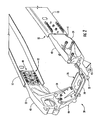
- the frame arms 22, 24 are connected to the frame members 12, 13 by way of joint assemblies 32, which are shown in greater details in Figures 4 and 5 .
- the frame arms 22, 24 are configured to extend forward of the frame members 12, 13.
- the frame arms 22, 24 each comprise an interface portion 40, 41 that connects to a respective frame member 12, 13, a longitudinally extending body 42, 43 that extends forward of the interface portion 40, 41, and a downwardly depending and transversely angled leg 44, 45 that connects to the engine support member 26.
- the engine support member 26 includes a cradle 50 to support an engine. Flanges 52, 54 extending transversely and upwardly angled from opposite ends of the cradle 50. The flanges 52, 54 connect with the legs 44, 45 of the frame arms 22, 24.
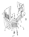
- FIG. 3 an exploded view of the joint 30 connecting the engine support member 26 to frame arm 22 is shown. It will be understood that the joint connecting the opposite flange 54 of the engine support member 26 to the frame arm 24 is a mirror image of the described joint.
- the joint 30 includes a first contoured interface surface 34 provided on the leg 44 depending downward from frame arm 22.
- a second contoured interface surface 56 is provided on the flange 52 of engine support 26.
- the contoured interface surfaces 34, 56 are each shaped with a plurality of protrusions and depressions which are arranged to mate and interengage upon assembly of the contoured interface surfaces to form the joint 30.
- the contoured interface surfaces 34, 56 are embodied as a plurality of parallel grooves and ridges.
- the contoured interface surfaces are complementary, that is, where the first interface surface 34 has protrusions, the second interface surface 56 has depressions, and vice versa.
- the interengagement of the protrusions and depressions interface surfaces provides resistance to both linear and torsional shear forces at the mating surfaces.
- the interengaged surfaces resist relative linear sliding movement and relative rotational sliding movement.
- the contoured interfaces surfaces forming a joint may each be formed of different materials with different hardness values, allowing some deformation of one surface as it engages with the mating surface.
- the protrusions and depressions are formed as ridges and grooves aligned with the transverse direction of the frame.
- This arrangement advantageously provides resistance to shear in the longitudinal direction (resisting displacement of the engine support 26 in a fore/aft direction).
- the arrangement additionally provides improved resistance to forces urging rotation of the flange 52 relative to the leg 44 of the frame arm 22 (resisting relative pivoting of the engine support 26 and the accompanying paralleling of the frame rails), which may occur in vehicle cornering or turning movements.
- Resistance to paralleling of the frames advantageously improves vehicle roll resistance.
- the mating flange 52 and leg 44 are fastened by a plurality of bolts 46 and nuts 48 extending through aligned holes provided in the flange and leg.
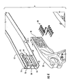
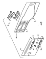
- the joint 32 includes a first contoured interface surface 60 provided on the frame rail 12 and a second contoured interface surface 62 (shown in Figure 5 ) provided on the interface 40 of the frame arm 22.
- the first contoured interface surface 60 and the second contoured interface surface 62 are formed with protrusions and depressions, similar to those of the contoured interfaces 34, 56 of Figure 3 .
- the contoured interface surface 60 in the illustrated embodiment includes grooves and ridges extending in the longitudinal direction and arranged in groups at the top, center, and bottom portions of the surface 60, and grooves and ridges obliquely oriented arranged in groups between the top and center grooves and ridges and between the center and bottom grooves and ridges.
- This combination of protrusions and depressions helps resist linear shear in the longitudinal direction and vertical direction, and provides resistance to relative rotation of the interface surfaces.
- the contoured interface surface 62 on the arm 22 is formed in a complementary manner, having grooves to accept the ridges, and ridges to accept the grooves of the contoured interface surface 60 provided on the frame member 12. This arrangement also facilitates aligning and mating the joint members during assembly.
- the contoured interface surface 60 is formed on an interface plate 64 which is mounted to the first frame member 12.
- the interface plate 64 may be mounted to the frame member 12 by rivets 70 as shown. Alternatively, the interface plate 64 may be mounted by bolts and nuts, welding, adhesive, or another suitable permanent or semi-permanent fastening system.
- a plurality of holes 72 is provided in the interface plate 64 and a second plurality 74 for alignment with the first plurality 72 is provided in the first frame member 12 for the illustrated rivets. Additional holes are provided in the frame member 12 and interface plate 64 for assembling the joint members, as will be described below.
- the frame member 22 in the illustrated embodiment is formed as a cast member, and may alternatively be a forged member, allowing the second contoured interface surface 62 to be formed directly on the second frame member 22.
- a second interface plate may be provided if the mating frame member is also a relatively thin member.
- the interface surface 62 of the interface portion 40 shown in Figure 5 includes spaced groups of grooves and ridges oriented in a longitudinal direction of the frame and a plurality of obliquely oriented ridges and grooves, complementary to the grooves and ridges of the interface surface 60 of the interface plate 64.
- the interface plate 64 is secured to the frame member 12 by, for example, rivets 70, as mentioned above.
- the second frame member 22 is placed with the second contoured interface surface 62 in mating contact with the first contoured interface surface 60 interengaging the surfaces.
- a plurality of fasteners, for example, bolts 80 are positioned in aligned holes in the respective second frame member 22, interface plate 64 and first frame member 12, and secured with a respective plurality of nuts 82.
- FIG. 6 shows an alternative contoured interface surface 60a illustrated, for convenience, on an interface plate 64a.
- a plurality of concentric grooves and ridges 84, circular or non-circular (as shown), are formed on the surface 60a.
- the concentric grooves and ridges may be in a single group or arranged in a plurality of groups.
- FIG. 6 Another embodiment of a contoured interface surface 60b is shown on an interface plate 64b in Figure 7 and integrated with grooves and ridges similar to those shown in the interface surface 60 of Figure 4 .
- a plurality of bumps and cavities 88 are formed on the interface surface 60b.
Landscapes
- Engineering & Computer Science (AREA)
- Chemical & Material Sciences (AREA)
- Combustion & Propulsion (AREA)
- Transportation (AREA)
- Mechanical Engineering (AREA)
- Body Structure For Vehicles (AREA)
Claims (7)
- Fahrzeugrahmenelement-Strukturverbindung (32), umfassend
eine Schnittstellenplatte (64), die an einem ersten Rahmenelement (12) montierbar ist, wobei die Schnittstellenplatte eine konturierte Schnittstellenoberfläche (60) aufweist, die mit wenigstens einem Vorsprung und wenigstens einer Vertiefung versehen ist,
ein zweites Rahmenelement (22) und
eine Vielzahl von lösbaren Befestigungselementen,
dadurch gekennzeichnet, dass
das zweite Rahmenelement (22) eine konturierte, mit wenigstens einem Vorsprung und wenigstens einer Vertiefung versehene Schnittstellenoberfläche (62) aufweist, die komplementär zur konturierten Schnittstellenoberfläche (60) der Schnittstellenplatte (64) für einen Eingriff damit ist, und
die Vielzahl von lösbaren Befestigungselementen für eine lösbare Befestigung des zweiten Rahmenelements (20) an der Schnittstellenplatte (64) vorgesehen sind, wobei die Vielzahl der Befestigungselemente so konfiguriert sind, dass sie in fluchtenden Öffnungen in dem jeweiligen zweiten Rahmenelement (22), der Schnittstellenplatte (64) und dem ersten Rahmenelement (12) positioniert werden, so dass die konturierten Schnittstellenoberflächen miteinander in Eingriff stehen, um Linear- und Torsionsscherkräften zu widerstehen. - Fahrzeugrahmenelement-Strukturverbindung nach Anspruch 1, wobei die konturierten Schnittstellenoberflächen der Schnittstellenplatte und des zweiten Rahmenelements jeweils eine Vielzahl von Rippen und Nuten aufweisen.
- Fahrzeugrahmenelement-Strukturverbindung nach Anspruch 2, wobei die konturierten Schnittstellenoberflächen der Schnittstellenplatte und des zweiten Rahmenelements außerdem eine zweite Vielzahl von Rippen und Nuten umfassen, die schräg zu der Vielzahl von Rippen und Nuten ausgerichtet sind.
- Fahrzeugrahmenelement-Strukturverbindung nach Anspruch 2, wobei die Vielzahl von Rippen und Nuten in einer Längsrichtung des Fahrzeugrahmens ausgerichtet sind, an dem die Verbindung montiert ist.
- Fahrzeugrahmenelement-Strukturverbindung nach Anspruch 1, wobei die konturierte Schnittstellenoberfläche der Schnittstellenplatte und die konturierte Schnittstellenoberfläche des zweiten Rahmenelements aus verschiedenen Materialien mit unterschiedlichen Härtewerten gebildet sind.
- Fahrzeugrahmenelement-Strukturverbindung nach Anspruch 1, wobei die konturierten Schnittstellenoberflächen des ersten Rahmenelements und des zweiten Rahmenelements jeweils eine Vielzahl von Vorsprüngen und Vertiefungen aufweisen.
- Fahrzeugrahmenelement-Strukturverbindung nach Anspruch 1, wobei die konturierten Schnittstellenoberflächen des ersten Rahmenelements und des zweiten Rahmenelements jeweils konzentrisch angeordnete Nuten und Rippen aufweisen.
Applications Claiming Priority (1)
| Application Number | Priority Date | Filing Date | Title |
|---|---|---|---|
| PCT/US2008/010693 WO2010030257A1 (en) | 2008-09-12 | 2008-09-12 | Structural joint for a commercial vehicle frame and a frame made with a structural joint |
Publications (3)
| Publication Number | Publication Date |
|---|---|
| EP2334539A1 EP2334539A1 (de) | 2011-06-22 |
| EP2334539A4 EP2334539A4 (de) | 2013-04-17 |
| EP2334539B1 true EP2334539B1 (de) | 2015-02-25 |
Family
ID=42005353
Family Applications (1)
| Application Number | Title | Priority Date | Filing Date |
|---|---|---|---|
| EP08815920.7A Not-in-force EP2334539B1 (de) | 2008-09-12 | 2008-09-12 | Strukturverbindung für einen nutzfahrzeugrahmen und mit einer strukturverbindung hergestellter rahmen |
Country Status (5)
| Country | Link |
|---|---|
| US (1) | US8485555B2 (de) |
| EP (1) | EP2334539B1 (de) |
| JP (1) | JP2012501913A (de) |
| CN (1) | CN102149591B (de) |
| WO (1) | WO2010030257A1 (de) |
Cited By (1)
| Publication number | Priority date | Publication date | Assignee | Title |
|---|---|---|---|---|
| WO2024068748A1 (de) * | 2022-09-30 | 2024-04-04 | Bayerische Motoren Werke Aktiengesellschaft | Träger für eine kraftwagenkarosserie sowie verfahren |
Families Citing this family (20)
| Publication number | Priority date | Publication date | Assignee | Title |
|---|---|---|---|---|
| JP5111409B2 (ja) * | 2009-02-02 | 2013-01-09 | ヤンマー株式会社 | 作業車輌 |
| DE102009019787A1 (de) * | 2009-05-02 | 2010-11-04 | Man Nutzfahrzeuge Ag | Trägeranordnung für einen Fahrzeugrahmen eines Nutzfahrzeuges |
| US8985631B2 (en) * | 2011-11-11 | 2015-03-24 | Norco Industries, Inc. | Trailer frame |
| DE102012013148A1 (de) * | 2012-07-03 | 2014-01-09 | Zf Friedrichshafen Ag | Kraftfahrzeug mit einem Fahrzeugrahmen |
| JP6118123B2 (ja) | 2013-02-14 | 2017-04-19 | 日野自動車株式会社 | 車両のフレーム構造 |
| US9802654B2 (en) * | 2013-07-22 | 2017-10-31 | GM Global Technology Operations LLC | Method of assembling a vehicle uniframe |
| US9796051B2 (en) | 2014-02-24 | 2017-10-24 | Metalsa S.A. De C.V. | Method and tools for welding a vehicle component |
| WO2015136384A2 (en) | 2014-02-24 | 2015-09-17 | Metalsa S.A. De C.V. | Pivoting tool for positioning automotive components |
| PL3197742T3 (pl) * | 2014-09-22 | 2021-04-06 | Siemens Mobility Austria Gmbh | Rama podwozia z jednostką napędową |
| DE102015221761A1 (de) * | 2015-11-05 | 2017-05-11 | Zf Friedrichshafen Ag | Fahrwerkanordnung sowie Querträger und Stütze für eine solche Fahrwerkanordnung |
| DE102016107048B4 (de) * | 2016-04-15 | 2021-06-24 | Saf-Holland Gmbh | Rahmeneinheit |
| DE102017114815A1 (de) * | 2017-07-03 | 2019-01-03 | HYMER GmbH & Co. KG | Reisemobil |
| CN107512311B (zh) * | 2017-07-12 | 2019-10-11 | 湖北航天技术研究院特种车辆技术中心 | 一种车架及车辆 |
| US11285999B2 (en) * | 2019-04-03 | 2022-03-29 | Fontaine Modification Company | Frame extension for vehicle |
| US11654975B2 (en) * | 2020-12-21 | 2023-05-23 | Am General Llc | Vehicle frame rails and methods of assembling vehicle frame rails |
| CN115071823B (zh) * | 2022-06-28 | 2024-05-03 | 一汽解放汽车有限公司 | 车架总成及具有其的车辆 |
| CN115092255B (zh) * | 2022-06-28 | 2024-05-03 | 一汽解放汽车有限公司 | 车架总成 |
| CN115009361B (zh) * | 2022-07-08 | 2024-07-09 | 中国北方车辆研究所 | 一种重载分段式车架与模块化悬架 |
| JP7374276B1 (ja) | 2022-09-28 | 2023-11-06 | 日立建機株式会社 | ダンプトラック |
| EP4556350A1 (de) * | 2023-11-17 | 2025-05-21 | Volvo Truck Corporation | Querträgeranordnung und montageverfahren für ein fahrzeugchassis |
Family Cites Families (25)
| Publication number | Priority date | Publication date | Assignee | Title |
|---|---|---|---|---|
| US910510A (en) | 1908-04-11 | 1909-01-26 | Daniel Davis | Vehicle-axle. |
| FR561281A (fr) | 1922-10-20 | 1923-10-19 | Système de liaison de poutres en bois | |
| DE2413013C3 (de) * | 1974-03-18 | 1978-05-11 | Siemens Ag, 1000 Berlin Und 8000 Muenchen | Schaltungsanordnung zur Gleichschaltung der Buchstaben-Ziffern-Ebenen mehrerer Ein-Ausgabevorrichtungen in Fernschreibern |
| US3968624A (en) | 1975-07-01 | 1976-07-13 | Unistrut Corporation | Connector fixture |
| FR2379922A1 (fr) | 1977-02-08 | 1978-09-01 | Dervaux Ets | Dispositif pour regler la longueur de cables divers |
| US4630960A (en) | 1983-07-11 | 1986-12-23 | Reeves Jr James B | Adjustable herringbone lock joint |
| KR960000768B1 (ko) * | 1990-04-09 | 1996-01-12 | 도꼬 떽꼬 가부시끼가이샤 | 아아치(arch)형 건축 구조체 |
| JPH0858623A (ja) * | 1994-08-26 | 1996-03-05 | Nissan Motor Co Ltd | 車両用ストラットタワーバー |
| JPH08144383A (ja) * | 1994-11-25 | 1996-06-04 | Nobutaka Tamura | 建築・土木構造用継手およびその構築法 |
| JPH09111892A (ja) * | 1995-10-20 | 1997-04-28 | Sumitomo Forestry Co Ltd | 接合部材 |
| ATE182299T1 (de) * | 1996-04-10 | 1999-08-15 | Alusuisse Lonza Services Ag | Profilverbindung |
| US6398262B1 (en) * | 2000-09-26 | 2002-06-04 | Dana Corporation | Modular subframe assembly for a motor vehicle |
| DE10107307B4 (de) | 2001-02-16 | 2007-10-31 | Spicer Gelenkwellenbau Gmbh & Co. Kg | Flanschmitnehmer |
| JP4016376B2 (ja) * | 2002-03-05 | 2007-12-05 | いすゞ自動車株式会社 | サイドメンバとクロスメンバとの連結構造 |
| US7144040B2 (en) * | 2002-03-19 | 2006-12-05 | Dana Corporation | Bi-metallic structural component for vehicle frame assembly |
| US6905137B2 (en) * | 2002-11-21 | 2005-06-14 | Volvo Trucks North America, Inc. | Composite cross member system |
| US6681489B1 (en) * | 2003-01-31 | 2004-01-27 | Metalsa Roanoke Inc | Method for manufacturing a vehicle frame assembly |
| JP2005075018A (ja) * | 2003-08-28 | 2005-03-24 | Hino Motors Ltd | 車両のフレーム構造 |
| US7389844B2 (en) * | 2004-11-19 | 2008-06-24 | Spartan Motors, Inc. | Heavy vehicle chassis having lowered rear portion |
| US7717498B2 (en) * | 2006-04-14 | 2010-05-18 | Metalsa Servicios Sde Rl | Reduced weight components for vehicle frame and method of making same |
| CN100519305C (zh) * | 2006-05-16 | 2009-07-29 | 中国国际海运集装箱(集团)股份有限公司 | 一种连接接头及带有其的车架主梁及该主梁的连接方法 |
| CN100569573C (zh) * | 2006-06-21 | 2009-12-16 | 中国国际海运集装箱(集团)股份有限公司 | 一种用于车架梁的组合式连接接头 |
| CN2926005Y (zh) * | 2006-06-22 | 2007-07-25 | 中国国际海运集装箱(集团)股份有限公司 | 一种互扣式连接接头 |
| EP2125495A1 (de) * | 2006-12-26 | 2009-12-02 | Renault Trucks | Chassisrahmen, insbesondere für ein schwerfahrzeug |
| DE102008016924A1 (de) * | 2008-04-02 | 2008-11-20 | Daimler Ag | Vorderfederbock für einen Lastkraftwagen |
-
2008
- 2008-09-12 JP JP2011526834A patent/JP2012501913A/ja active Pending
- 2008-09-12 US US13/063,102 patent/US8485555B2/en not_active Expired - Fee Related
- 2008-09-12 CN CN200880131098.7A patent/CN102149591B/zh not_active Expired - Fee Related
- 2008-09-12 WO PCT/US2008/010693 patent/WO2010030257A1/en not_active Ceased
- 2008-09-12 EP EP08815920.7A patent/EP2334539B1/de not_active Not-in-force
Cited By (1)
| Publication number | Priority date | Publication date | Assignee | Title |
|---|---|---|---|---|
| WO2024068748A1 (de) * | 2022-09-30 | 2024-04-04 | Bayerische Motoren Werke Aktiengesellschaft | Träger für eine kraftwagenkarosserie sowie verfahren |
Also Published As
| Publication number | Publication date |
|---|---|
| WO2010030257A1 (en) | 2010-03-18 |
| CN102149591A (zh) | 2011-08-10 |
| US8485555B2 (en) | 2013-07-16 |
| CN102149591B (zh) | 2014-02-12 |
| US20110163527A1 (en) | 2011-07-07 |
| EP2334539A1 (de) | 2011-06-22 |
| EP2334539A4 (de) | 2013-04-17 |
| JP2012501913A (ja) | 2012-01-26 |
Similar Documents
| Publication | Publication Date | Title |
|---|---|---|
| US8485555B2 (en) | Structural joint for a commercial vehicle frame and a frame made with a structural joint | |
| EP2429840B1 (de) | Aufhängungssystem für schwerlast- und nutzfahrzeuge | |
| JP5238816B2 (ja) | ピックアップトラック用荷台およびその製造方法 | |
| US20060219462A1 (en) | Forward frame part for a utility vehicle | |
| JPS6050626B2 (ja) | 自動車フレ−ム | |
| CN105083381A (zh) | 用于载货车的底盘 | |
| CN102712230A (zh) | 重型轴-梁连接件 | |
| EP2234866B1 (de) | Befestigungsanordnung | |
| CN220615948U (zh) | 一种车架结构 | |
| JP2002542102A (ja) | 車両用荷重担持構造 | |
| EP2429839B1 (de) | Konsole zur befestigung einer längslenker | |
| US11498470B2 (en) | Rocker support assembly | |
| US11518288B2 (en) | Rocker support insert | |
| US6357360B1 (en) | Frame brace and center clamp | |
| CN216969347U (zh) | 支承连接组件及车辆 | |
| CN220220894U (zh) | 用于电动汽车的车架总成和具有其的电动汽车 | |
| CN216546364U (zh) | 一种一体式车架梁体及车架总成 | |
| CN223014715U (zh) | 底盘和车辆 | |
| CN2753648Y (zh) | 一种新型重型汽车车架横梁 | |
| CN218662034U (zh) | 前副车架及车辆 | |
| EP3959116B1 (de) | Fahrzeugchassis mit zweiwandigen balken mit aufhängungsmontagestruktur | |
| GB2553328A (en) | Improved vehicle chassis and chassis assembly method | |
| US12617467B2 (en) | Transverse cross-member assembly and mounting methods for a vehicle chassis | |
| CN121929230A (zh) | 一种车架及具有其的车辆 | |
| CN210555115U (zh) | 一种用于载货车的管状横梁总成 |
Legal Events
| Date | Code | Title | Description |
|---|---|---|---|
| PUAI | Public reference made under article 153(3) epc to a published international application that has entered the european phase |
Free format text: ORIGINAL CODE: 0009012 |
|
| 17P | Request for examination filed |
Effective date: 20110412 |
|
| AK | Designated contracting states |
Kind code of ref document: A1 Designated state(s): AT BE BG CH CY CZ DE DK EE ES FI FR GB GR HR HU IE IS IT LI LT LU LV MC MT NL NO PL PT RO SE SI SK TR |
|
| AX | Request for extension of the european patent |
Extension state: AL BA MK RS |
|
| DAX | Request for extension of the european patent (deleted) | ||
| A4 | Supplementary search report drawn up and despatched |
Effective date: 20130315 |
|
| RIC1 | Information provided on ipc code assigned before grant |
Ipc: B62D 27/06 20060101ALN20130311BHEP Ipc: B62D 21/02 20060101ALN20130311BHEP Ipc: B62D 21/12 20060101ALN20130311BHEP Ipc: B62D 21/00 20060101AFI20130311BHEP Ipc: B62D 21/11 20060101ALN20130311BHEP |
|
| 17Q | First examination report despatched |
Effective date: 20140207 |
|
| RIC1 | Information provided on ipc code assigned before grant |
Ipc: B62D 21/00 20060101AFI20140731BHEP Ipc: B62D 27/06 20060101ALN20140731BHEP Ipc: B62D 21/12 20060101ALN20140731BHEP Ipc: B62D 21/02 20060101ALN20140731BHEP Ipc: B62D 21/11 20060101ALN20140731BHEP |
|
| GRAP | Despatch of communication of intention to grant a patent |
Free format text: ORIGINAL CODE: EPIDOSNIGR1 |
|
| INTG | Intention to grant announced |
Effective date: 20140912 |
|
| GRAS | Grant fee paid |
Free format text: ORIGINAL CODE: EPIDOSNIGR3 |
|
| GRAA | (expected) grant |
Free format text: ORIGINAL CODE: 0009210 |
|
| AK | Designated contracting states |
Kind code of ref document: B1 Designated state(s): AT BE BG CH CY CZ DE DK EE ES FI FR GB GR HR HU IE IS IT LI LT LU LV MC MT NL NO PL PT RO SE SI SK TR |
|
| REG | Reference to a national code |
Ref country code: GB Ref legal event code: FG4D |
|
| REG | Reference to a national code |
Ref country code: CH Ref legal event code: EP |
|
| REG | Reference to a national code |
Ref country code: IE Ref legal event code: FG4D |
|
| REG | Reference to a national code |
Ref country code: DE Ref legal event code: R096 Ref document number: 602008036837 Country of ref document: DE Effective date: 20150409 |
|
| REG | Reference to a national code |
Ref country code: AT Ref legal event code: REF Ref document number: 711695 Country of ref document: AT Kind code of ref document: T Effective date: 20150415 |
|
| REG | Reference to a national code |
Ref country code: NL Ref legal event code: VDEP Effective date: 20150225 |
|
| REG | Reference to a national code |
Ref country code: AT Ref legal event code: MK05 Ref document number: 711695 Country of ref document: AT Kind code of ref document: T Effective date: 20150225 |
|
| REG | Reference to a national code |
Ref country code: LT Ref legal event code: MG4D |
|
| PG25 | Lapsed in a contracting state [announced via postgrant information from national office to epo] |
Ref country code: FI Free format text: LAPSE BECAUSE OF FAILURE TO SUBMIT A TRANSLATION OF THE DESCRIPTION OR TO PAY THE FEE WITHIN THE PRESCRIBED TIME-LIMIT Effective date: 20150225 Ref country code: ES Free format text: LAPSE BECAUSE OF FAILURE TO SUBMIT A TRANSLATION OF THE DESCRIPTION OR TO PAY THE FEE WITHIN THE PRESCRIBED TIME-LIMIT Effective date: 20150225 Ref country code: NO Free format text: LAPSE BECAUSE OF FAILURE TO SUBMIT A TRANSLATION OF THE DESCRIPTION OR TO PAY THE FEE WITHIN THE PRESCRIBED TIME-LIMIT Effective date: 20150525 Ref country code: HR Free format text: LAPSE BECAUSE OF FAILURE TO SUBMIT A TRANSLATION OF THE DESCRIPTION OR TO PAY THE FEE WITHIN THE PRESCRIBED TIME-LIMIT Effective date: 20150225 Ref country code: LT Free format text: LAPSE BECAUSE OF FAILURE TO SUBMIT A TRANSLATION OF THE DESCRIPTION OR TO PAY THE FEE WITHIN THE PRESCRIBED TIME-LIMIT Effective date: 20150225 Ref country code: SE Free format text: LAPSE BECAUSE OF FAILURE TO SUBMIT A TRANSLATION OF THE DESCRIPTION OR TO PAY THE FEE WITHIN THE PRESCRIBED TIME-LIMIT Effective date: 20150225 |
|
| PG25 | Lapsed in a contracting state [announced via postgrant information from national office to epo] |
Ref country code: IS Free format text: LAPSE BECAUSE OF FAILURE TO SUBMIT A TRANSLATION OF THE DESCRIPTION OR TO PAY THE FEE WITHIN THE PRESCRIBED TIME-LIMIT Effective date: 20150625 Ref country code: LV Free format text: LAPSE BECAUSE OF FAILURE TO SUBMIT A TRANSLATION OF THE DESCRIPTION OR TO PAY THE FEE WITHIN THE PRESCRIBED TIME-LIMIT Effective date: 20150225 Ref country code: AT Free format text: LAPSE BECAUSE OF FAILURE TO SUBMIT A TRANSLATION OF THE DESCRIPTION OR TO PAY THE FEE WITHIN THE PRESCRIBED TIME-LIMIT Effective date: 20150225 Ref country code: GR Free format text: LAPSE BECAUSE OF FAILURE TO SUBMIT A TRANSLATION OF THE DESCRIPTION OR TO PAY THE FEE WITHIN THE PRESCRIBED TIME-LIMIT Effective date: 20150526 |
|
| PG25 | Lapsed in a contracting state [announced via postgrant information from national office to epo] |
Ref country code: NL Free format text: LAPSE BECAUSE OF FAILURE TO SUBMIT A TRANSLATION OF THE DESCRIPTION OR TO PAY THE FEE WITHIN THE PRESCRIBED TIME-LIMIT Effective date: 20150225 |
|
| PG25 | Lapsed in a contracting state [announced via postgrant information from national office to epo] |
Ref country code: CZ Free format text: LAPSE BECAUSE OF FAILURE TO SUBMIT A TRANSLATION OF THE DESCRIPTION OR TO PAY THE FEE WITHIN THE PRESCRIBED TIME-LIMIT Effective date: 20150225 Ref country code: SK Free format text: LAPSE BECAUSE OF FAILURE TO SUBMIT A TRANSLATION OF THE DESCRIPTION OR TO PAY THE FEE WITHIN THE PRESCRIBED TIME-LIMIT Effective date: 20150225 Ref country code: EE Free format text: LAPSE BECAUSE OF FAILURE TO SUBMIT A TRANSLATION OF THE DESCRIPTION OR TO PAY THE FEE WITHIN THE PRESCRIBED TIME-LIMIT Effective date: 20150225 Ref country code: DK Free format text: LAPSE BECAUSE OF FAILURE TO SUBMIT A TRANSLATION OF THE DESCRIPTION OR TO PAY THE FEE WITHIN THE PRESCRIBED TIME-LIMIT Effective date: 20150225 Ref country code: RO Free format text: LAPSE BECAUSE OF FAILURE TO SUBMIT A TRANSLATION OF THE DESCRIPTION OR TO PAY THE FEE WITHIN THE PRESCRIBED TIME-LIMIT Effective date: 20150225 |
|
| REG | Reference to a national code |
Ref country code: DE Ref legal event code: R097 Ref document number: 602008036837 Country of ref document: DE |
|
| PG25 | Lapsed in a contracting state [announced via postgrant information from national office to epo] |
Ref country code: PL Free format text: LAPSE BECAUSE OF FAILURE TO SUBMIT A TRANSLATION OF THE DESCRIPTION OR TO PAY THE FEE WITHIN THE PRESCRIBED TIME-LIMIT Effective date: 20150225 |
|
| PG25 | Lapsed in a contracting state [announced via postgrant information from national office to epo] |
Ref country code: IT Free format text: LAPSE BECAUSE OF FAILURE TO SUBMIT A TRANSLATION OF THE DESCRIPTION OR TO PAY THE FEE WITHIN THE PRESCRIBED TIME-LIMIT Effective date: 20150225 |
|
| PLBE | No opposition filed within time limit |
Free format text: ORIGINAL CODE: 0009261 |
|
| STAA | Information on the status of an ep patent application or granted ep patent |
Free format text: STATUS: NO OPPOSITION FILED WITHIN TIME LIMIT |
|
| 26N | No opposition filed |
Effective date: 20151126 |
|
| PG25 | Lapsed in a contracting state [announced via postgrant information from national office to epo] |
Ref country code: SI Free format text: LAPSE BECAUSE OF FAILURE TO SUBMIT A TRANSLATION OF THE DESCRIPTION OR TO PAY THE FEE WITHIN THE PRESCRIBED TIME-LIMIT Effective date: 20150225 |
|
| PG25 | Lapsed in a contracting state [announced via postgrant information from national office to epo] |
Ref country code: LU Free format text: LAPSE BECAUSE OF FAILURE TO SUBMIT A TRANSLATION OF THE DESCRIPTION OR TO PAY THE FEE WITHIN THE PRESCRIBED TIME-LIMIT Effective date: 20150912 Ref country code: MC Free format text: LAPSE BECAUSE OF FAILURE TO SUBMIT A TRANSLATION OF THE DESCRIPTION OR TO PAY THE FEE WITHIN THE PRESCRIBED TIME-LIMIT Effective date: 20150225 |
|
| REG | Reference to a national code |
Ref country code: CH Ref legal event code: PL |
|
| GBPC | Gb: european patent ceased through non-payment of renewal fee |
Effective date: 20150912 |
|
| PG25 | Lapsed in a contracting state [announced via postgrant information from national office to epo] |
Ref country code: BE Free format text: LAPSE BECAUSE OF FAILURE TO SUBMIT A TRANSLATION OF THE DESCRIPTION OR TO PAY THE FEE WITHIN THE PRESCRIBED TIME-LIMIT Effective date: 20150225 |
|
| REG | Reference to a national code |
Ref country code: IE Ref legal event code: MM4A |
|
| REG | Reference to a national code |
Ref country code: FR Ref legal event code: ST Effective date: 20160531 |
|
| PG25 | Lapsed in a contracting state [announced via postgrant information from national office to epo] |
Ref country code: IE Free format text: LAPSE BECAUSE OF NON-PAYMENT OF DUE FEES Effective date: 20150912 Ref country code: GB Free format text: LAPSE BECAUSE OF NON-PAYMENT OF DUE FEES Effective date: 20150912 Ref country code: LI Free format text: LAPSE BECAUSE OF NON-PAYMENT OF DUE FEES Effective date: 20150930 Ref country code: CH Free format text: LAPSE BECAUSE OF NON-PAYMENT OF DUE FEES Effective date: 20150930 |
|
| PG25 | Lapsed in a contracting state [announced via postgrant information from national office to epo] |
Ref country code: FR Free format text: LAPSE BECAUSE OF NON-PAYMENT OF DUE FEES Effective date: 20150930 |
|
| PG25 | Lapsed in a contracting state [announced via postgrant information from national office to epo] |
Ref country code: MT Free format text: LAPSE BECAUSE OF FAILURE TO SUBMIT A TRANSLATION OF THE DESCRIPTION OR TO PAY THE FEE WITHIN THE PRESCRIBED TIME-LIMIT Effective date: 20150225 |
|
| PG25 | Lapsed in a contracting state [announced via postgrant information from national office to epo] |
Ref country code: BG Free format text: LAPSE BECAUSE OF FAILURE TO SUBMIT A TRANSLATION OF THE DESCRIPTION OR TO PAY THE FEE WITHIN THE PRESCRIBED TIME-LIMIT Effective date: 20150225 Ref country code: HU Free format text: LAPSE BECAUSE OF FAILURE TO SUBMIT A TRANSLATION OF THE DESCRIPTION OR TO PAY THE FEE WITHIN THE PRESCRIBED TIME-LIMIT; INVALID AB INITIO Effective date: 20080912 |
|
| PG25 | Lapsed in a contracting state [announced via postgrant information from national office to epo] |
Ref country code: CY Free format text: LAPSE BECAUSE OF FAILURE TO SUBMIT A TRANSLATION OF THE DESCRIPTION OR TO PAY THE FEE WITHIN THE PRESCRIBED TIME-LIMIT Effective date: 20150225 |
|
| PG25 | Lapsed in a contracting state [announced via postgrant information from national office to epo] |
Ref country code: TR Free format text: LAPSE BECAUSE OF FAILURE TO SUBMIT A TRANSLATION OF THE DESCRIPTION OR TO PAY THE FEE WITHIN THE PRESCRIBED TIME-LIMIT Effective date: 20150225 |
|
| PGFP | Annual fee paid to national office [announced via postgrant information from national office to epo] |
Ref country code: DE Payment date: 20170926 Year of fee payment: 10 |
|
| PG25 | Lapsed in a contracting state [announced via postgrant information from national office to epo] |
Ref country code: PT Free format text: LAPSE BECAUSE OF FAILURE TO SUBMIT A TRANSLATION OF THE DESCRIPTION OR TO PAY THE FEE WITHIN THE PRESCRIBED TIME-LIMIT Effective date: 20150225 |
|
| REG | Reference to a national code |
Ref country code: DE Ref legal event code: R119 Ref document number: 602008036837 Country of ref document: DE |
|
| PG25 | Lapsed in a contracting state [announced via postgrant information from national office to epo] |
Ref country code: DE Free format text: LAPSE BECAUSE OF NON-PAYMENT OF DUE FEES Effective date: 20190402 |