EP2334883B1 - Système de libération de verrou - Google Patents
Système de libération de verrou Download PDFInfo
- Publication number
- EP2334883B1 EP2334883B1 EP09753054.7A EP09753054A EP2334883B1 EP 2334883 B1 EP2334883 B1 EP 2334883B1 EP 09753054 A EP09753054 A EP 09753054A EP 2334883 B1 EP2334883 B1 EP 2334883B1
- Authority
- EP
- European Patent Office
- Prior art keywords
- force
- latch release
- release system
- handle
- spring
- Prior art date
- Legal status (The legal status is an assumption and is not a legal conclusion. Google has not performed a legal analysis and makes no representation as to the accuracy of the status listed.)
- Not-in-force
Links
- 230000033001 locomotion Effects 0.000 claims description 16
- 230000009849 deactivation Effects 0.000 claims 2
- 230000001419 dependent effect Effects 0.000 claims 2
- 229910000831 Steel Inorganic materials 0.000 description 9
- 239000010959 steel Substances 0.000 description 9
- 230000005540 biological transmission Effects 0.000 description 8
- 230000001133 acceleration Effects 0.000 description 4
- 239000002245 particle Substances 0.000 description 4
- 230000000903 blocking effect Effects 0.000 description 3
- 239000000696 magnetic material Substances 0.000 description 3
- 239000000463 material Substances 0.000 description 3
- 210000000078 claw Anatomy 0.000 description 2
- 239000002131 composite material Substances 0.000 description 2
- 230000006835 compression Effects 0.000 description 2
- 238000007906 compression Methods 0.000 description 2
- 239000006249 magnetic particle Substances 0.000 description 2
- 229920003023 plastic Polymers 0.000 description 2
- 239000004033 plastic Substances 0.000 description 2
- 230000009471 action Effects 0.000 description 1
- 238000013459 approach Methods 0.000 description 1
- 230000008901 benefit Effects 0.000 description 1
- 230000008859 change Effects 0.000 description 1
- 230000003111 delayed effect Effects 0.000 description 1
- 231100001261 hazardous Toxicity 0.000 description 1
- 230000003993 interaction Effects 0.000 description 1
- 238000002955 isolation Methods 0.000 description 1
- 238000000034 method Methods 0.000 description 1
- 230000008569 process Effects 0.000 description 1
- 230000009467 reduction Effects 0.000 description 1
Images


Classifications
-
- E—FIXED CONSTRUCTIONS
- E05—LOCKS; KEYS; WINDOW OR DOOR FITTINGS; SAFES
- E05B—LOCKS; ACCESSORIES THEREFOR; HANDCUFFS
- E05B77/00—Vehicle locks characterised by special functions or purposes
- E05B77/02—Vehicle locks characterised by special functions or purposes for accident situations
- E05B77/12—Automatic locking or unlocking at the moment of collision
-
- E—FIXED CONSTRUCTIONS
- E05—LOCKS; KEYS; WINDOW OR DOOR FITTINGS; SAFES
- E05B—LOCKS; ACCESSORIES THEREFOR; HANDCUFFS
- E05B77/00—Vehicle locks characterised by special functions or purposes
- E05B77/02—Vehicle locks characterised by special functions or purposes for accident situations
- E05B77/04—Preventing unwanted lock actuation, e.g. unlatching, at the moment of collision
- E05B77/06—Preventing unwanted lock actuation, e.g. unlatching, at the moment of collision by means of inertial forces
-
- E—FIXED CONSTRUCTIONS
- E05—LOCKS; KEYS; WINDOW OR DOOR FITTINGS; SAFES
- E05B—LOCKS; ACCESSORIES THEREFOR; HANDCUFFS
- E05B77/00—Vehicle locks characterised by special functions or purposes
- E05B77/42—Means for damping the movement of lock parts, e.g. slowing down the return movement of a handle
-
- E—FIXED CONSTRUCTIONS
- E05—LOCKS; KEYS; WINDOW OR DOOR FITTINGS; SAFES
- E05B—LOCKS; ACCESSORIES THEREFOR; HANDCUFFS
- E05B85/00—Details of vehicle locks not provided for in groups E05B77/00 - E05B83/00
- E05B85/10—Handles
-
- Y—GENERAL TAGGING OF NEW TECHNOLOGICAL DEVELOPMENTS; GENERAL TAGGING OF CROSS-SECTIONAL TECHNOLOGIES SPANNING OVER SEVERAL SECTIONS OF THE IPC; TECHNICAL SUBJECTS COVERED BY FORMER USPC CROSS-REFERENCE ART COLLECTIONS [XRACs] AND DIGESTS
- Y10—TECHNICAL SUBJECTS COVERED BY FORMER USPC
- Y10T—TECHNICAL SUBJECTS COVERED BY FORMER US CLASSIFICATION
- Y10T292/00—Closure fasteners
- Y10T292/03—Miscellaneous
-
- Y—GENERAL TAGGING OF NEW TECHNOLOGICAL DEVELOPMENTS; GENERAL TAGGING OF CROSS-SECTIONAL TECHNOLOGIES SPANNING OVER SEVERAL SECTIONS OF THE IPC; TECHNICAL SUBJECTS COVERED BY FORMER USPC CROSS-REFERENCE ART COLLECTIONS [XRACs] AND DIGESTS
- Y10—TECHNICAL SUBJECTS COVERED BY FORMER USPC
- Y10T—TECHNICAL SUBJECTS COVERED BY FORMER US CLASSIFICATION
- Y10T292/00—Closure fasteners
- Y10T292/11—Magnetic
-
- Y—GENERAL TAGGING OF NEW TECHNOLOGICAL DEVELOPMENTS; GENERAL TAGGING OF CROSS-SECTIONAL TECHNOLOGIES SPANNING OVER SEVERAL SECTIONS OF THE IPC; TECHNICAL SUBJECTS COVERED BY FORMER USPC CROSS-REFERENCE ART COLLECTIONS [XRACs] AND DIGESTS
- Y10—TECHNICAL SUBJECTS COVERED BY FORMER USPC
- Y10T—TECHNICAL SUBJECTS COVERED BY FORMER US CLASSIFICATION
- Y10T292/00—Closure fasteners
- Y10T292/57—Operators with knobs or handles
Definitions
- the present invention relates to a latch release system for releasing a latch, in particular a latch for a land vehicle such as a car (automobile).
- Cars include passenger doors which can be held in a closed position by a door latch. Operation of an outside door handle or an inside door handle will release the latch thereby allowing the door to be opened.
- the outside door handle is pivotally mounted on the associated door and by pulling on the outside handle an actuating system within the door operates to move either a Bowden cable or a rod. The Bowden cable or rod is connected to a door latch and movement on the Bowden cable or rod releases the door latch thereby allowing the door to be opened.
- An inside handle is typically pivoted about a vertically orientated pivot.
- An outside handle is typically pivoted about a vertically orientated pivot position towards the front of the handle.
- an outside handle may be pivoted about a horizontally mounted pivot so that the handle moves outwards and upwards when pulled.
- the handle possesses a mass and during a side impact on the vehicle the inertia of the handle can cause it to move in its opening direction relative to the door thereby allowing the door to open during the crash sequence. This is hazardous to occupants of the vehicle since the passenger safety cell of the vehicle relies on the door to remain closed during a crash.
- US 2008/0036219 shows a system where, in the event of a side impact the outside door handle is prevented from moving to its fully open position by a blocking arrangement. However, after the side impact has finished, and the vehicle has come to rest, the blocking system remains in place and it is not possible to release the latch using the door handle.
- a latch release system for releasing a latch, the system having a rest position and an actuated position and requiring a first force to move the system from the rest position to the actuated position, the system including an inertia event sensor and a means for increasing the force required to operate system, wherein when the inertia event sensor detects an inertia event it activates said means so the system requires a second force, greater than the first force, to move the system to the actuated position.
- the invention allows the second force to be set at a relatively high level, in particular a level higher than the highest envisaged opening force on that handle that will occur as a result of inertia during a crash.
- latches are designed to withstand certain lateral G acceleration levels.
- the highest envisaged lateral G acceleration occurring might be, for example, 650 G.
- Such a 650 G acceleration might equate to inertia force on the door handle creating for example a 250N opening load.
- the door must remain closed.
- the means for increasing the force required to open the latch might, by way of example, increase the opening force to 300N. As such the latch will remain engaged, but nevertheless the handle is never blocked from opening the latch since by applying a (manual) 300N load to the handle after the crash, i.e. once the vehicle has come to rest, the latch will always open.
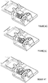
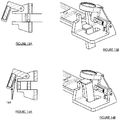
- a latch release system in the form of a door handle assembly 10.
- the door handle assembly 10 is mounted on a door 11 (shown schematically and only shown in Fig. 3A ).
- the door handle assembly 10 includes a door handle 12 which includes a hand-operable portion 20 (shown schematically and only shown in Fig. 1A ) connected to a handle strap 22.
- the handle strap 22 is connected by a transmission path 80 to a known latch 81 which is also mounted on the door 11.
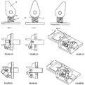
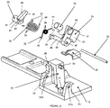
- Fig. 19 shows the various components of the door handle assembly in more detail.
- the handle strap 22 includes a pin 24.
- the door handle 12 is pivotally mounted to the handle chassis about a vertically orientated pivot (not shown).
- the handle chassis includes lugs 25 and 26 with respective holes 25A and 26A.
- the handle chassis also includes a spring abutment 27 and abutments 28.
- the handle chassis is made from a non-magnetic material, in this case a plastics material.
- plate 29 Secured to the handle chassis is a piece of magnetic material in the form of a plate 29.
- plate 29 is made from sheet steel.
- the door handle assembly also includes a pivot pin 30, a first spring 31, a second spring 32, a first lever 33, a second lever 34 and a magnet 35.
- the first spring has a series of coils 36, a first arm 37 and a second arm 38.
- the second spring 32 has a series of coils 39, a first arm 40 and a second arm 41.
- the first lever 33 has a generally cylindrical portion 42 having a central hole 43. Projecting generally tangentially from the cylindrical portion 42 is an arm 44 having a first engagement surface 45, a second engagement surface 46 and an abutment 47.
- the second lever 43 has a generally cylindrical portion 48 which has a central hole 49.
- a first arm 50 having an abutment surface 51, a recess 52, a spring abutment 53 and a spring abutment 56.
- a second arm 54 At an opposite end of the generally cylindrical portion 48 is a second arm 54 with an abutment 55.
- the magnet 35 is generally cylindrical.
- the pivot pin 30 is mounted in holes 25A and 26A.
- the first lever is mounted on pivot pin 30 via central hole 43 and the second lever 34 is mounted on pivot pin 30 via central hole 49.
- the first lever 33 and second lever 34 can therefore rotate relative to pivot pin 30 as will be further described below.
- the coils 39 of the second spring 32 are mounted around the generally cylindrical portion 48 of the second lever 34.
- the coils 36 of the first spring 31 are mounted around the generally cylindrical portion 48 of the second lever 34.
- the first arm 37 of the first spring 31 engages the second engagement surface 46 of the first lever 33.
- the second arm 38 of the first spring 31 engages spring abutment 53 of the second lever 34.
- the first spring 31 therefore biases the first lever 33 anticlockwise when viewing Fig. 1B and it biases the second lever 34 clockwise when viewing Fig. 1A , such that abutment 47 of the first lever is in engagement with abutment 55 of the second lever 34 (see especially Fig. 1B ).
- First arm 40 of the second spring 32 engages the spring abutment 27 of the handle chassis 18.
- Second arm 41 of the second spring 32 engages spring abutment 56 of the second lever 34.
- the second spring 32 therefore biases the second lever 34 anticlockwise when viewing Fig. 1A .
- Magnet 35 is positioned within recess 52 and abuts lip 57 of the first arm 50.
- magnet 35 is spaced from plate 29 as shown in Fig. 1A , and arm 44 is beneath pin 24 when viewing Fig. 1B , i.e. arm 44 will not be restrict movement of handle 12 and pin 24 in the direction of arrow X.
- the door handle When it is desired to open the door, the door handle is moved in the direction of arrow X from the rest position as shown in Fig. 9A to the actuator position as shown in Fig. 9B .
- a comparison of Figs. 9A and 9B show that the first spring 31, second spring 32, first lever 33 and second 34 are all in the same position.
- a handle return spring (not shown) will return handle from the Fig. 9B position to the Fig. 9A position.
- first arm 50 and magnet 35 cause the first lever 33 and second lever 34 to swing onto the Fig. 2A, 2B and 9C position.
- the second spring 32 is a relatively light spring, the first lever 33, second lever 34 and magnet 35 are able to achieve the Fig. 2A, 2B , 2C and 9C position before any significant movement of the door handle 12 has occurred.
- the engagement surface 45 lies in the path of pin 24.
- first spring 31 is a relatively heavy spring and therefore can create a force greater than the inertia force of the handle. As the crash continues, the handle therefore cannot move past the Fig. 3A, 3B , 3C and 9D position.
- the handle return spring (discussed above) will return the handle 12 from the Fig. 3A position to the rest position (as shown in Fig. 1A ).
- the relatively light second spring is unable to overcome the magnetic attraction between the magnet and the plate and hence both the first lever 33 and second lever 34 remain in the Fig. 3A, 3B , 3C position.
- the door handle 12 is pulled from its rest position through the Fig. 3A /B/C position, through the Fig. 4A /B/C position, through the Fig. 5A /B/C position to the Fig. 6A /B/C position whereupon the handle is in its fully actuated position and the latch releases as described above.
- the first lever 33 moves clockwise as the force of the first spring 31 is overcome until such time as the pin 24 moves past the end of arm 44 whereupon arm 44 "snaps back" under the returning influence of the first spring 31.
- the spring 32 will obey Hook's Law, whereas the magnetic force between the magnet 35 and plate 29 is not proportional with the distance between these two components, rather as the magnet approaches the plate the magnetic force increase disproportionately.
- the torque created by spring 32 tending to rotate the second lever anticlockwise is 12Nmm
- the Fig. 2A position it is 17Nmm, i.e. it has only increased by 42%.
- the magnetic force between the magnet and the plate creates a torque of less than 0.1Nmm tending to rotate the second lever in a clockwise direction
- Fig. 2A position it creates a torque of 150Nmm, i.e. an increase of over 1500%.
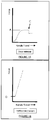
- Fig. 15 shows a graph of the handle travel of door handle 10 versus the force required to pull the handle under normal opening conditions.
- the force required to pull the handle progressively increases up to a level A.
- Position C is the point at which the latch is released and a force required to pull the handle beyond this position suddenly drops.
- Fig. 16 shows the force generated by a first spring 31 assuming the engagement surface 45 is in the path of pin 24. Note that there is an initial handle travel where the spring fore is zero and this equates to the handle travel between the Fig. 2B position and Fig. 3B position. Once contact is made between pin 24 and engagement surface 45 at the Fig. 3B position the force immediately jumps to level D, and this is because spring 31 is pre-tensioned. It will be appreciated that the line shown on Fig. 16 is relatively steep.
- Fig. 17 is a composite graph showing the graph of Fig. 15 , the graph of Fig. 16 and the resultant handle load.
- the initial part of the graph E follows the Fig. 15 graph.
- the components are in the Fig. 3B position and the graph immediately climbs to point G.
- Continued handle travel requires a force to overcome the normal opening force ( Fig. 15 ) and also requires an additional force to overcome the force created by the first spring 31 (the Fig. 16 graph) and as such the graph climbs steeply to point H.
- Point H represents the Fig. 4B position where the first lever 33 is just about to snap back.
- the handle no longer has to overcome the force generated by the first spring 31 and the graph falls to the I position, i.e. the graph falls to the equivalent point on the Fig. 15 graph. From point I onto point C the graph is the same as Fig. 15 .
- Fig. 18 shows the composite line of Fig. 17 is isolation.
- Fig. 17 shows a force D which equates to the maximum likely inertia force of the handle 12 in an opening direction (arrow X) seen during a side impact crash.
- the design of the system is such that the minimum force required to open the door (B) once the engagement surface 45 has been positioned in the path of pin 24 is greater than force D. As such, during a crash the door handle will not reach its fully actuated position and the door will not open.
- the door handle assembly 10 is a latch release system for releasing latch 81.
- the latch release system has a rest position ( Fig. 1A, 1B and 1C ) and an actuated position ( Fig. 6A, 6B and 6C ).
- the door handle assembly requires a first force (A) to move the handle from the rest position to the activated position.
- the door handle assembly also includes an inertia event sensor in the form of the first and second levers and the magnet.
- Door handle assembly also has a means for increasing the force required to operate the system (the first spring 31).
- Door handle assembly is arranged such that when the inertia event sensor detects an inertia event it activates the first spring 31 by causing the engagement surface 45 to lie in the path of pin 24. When so arranged the system requires a second force (B) higher than the first force (A) to move the handle to the actuated position.
- the door handle assembly defines a latch release system which has an intermediate position ( Fig. 5B ) between the rest position ( Fig. 1B ) and the activated position ( Fig. 6B ).
- the latch release system requires the second force (B) to move the latch release system (handle) to the intermediate position.
- the latch release system (handle assembly) only requires a third force (A) which is lower than the second force (B) to move the system from the intermediate position to the actuated position.
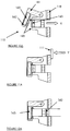
- Figs. 10A to 14B show a second embodiment of a latch release system in the form of a door handle assembly 110 in which components which fulfil the same function as door handle assembly 10 are labelled 100 greater.
- the handle strap 22 includes a steel plate 160. Significantly handle strap 22 does not include a pin equivalent to pin 24 of handle strap 22.
- Lever 161 is pivotally mounted about pin 124 and is biased into the Fig. 10A position by spring 132.
- Lever 161 is generally L-shaped and includes a recess 162 which includes a magnet 163. Lips 164 are provided next to magnet 163.
- the handle chassis 118 includes abutments 165 which engage the lips as will be further described below.
- the door handle When it is required to open the door the door handle is pulled moving the handle strap in the direction of arrow X to the Fig. 13A and 13B position, thereby opening the door. Once the door has been opened the handle is released and it returns under the action of a handle return spring (not shown) to the Fig. 14A and 14B position (the same position as Fig. 10A and 10B respectively). It will be appreciated that during the opening and closing sequence the lever 161 has not moved.
- the handle when the handle is in the Fig. 12A position the steel plate 160 is spaced from the magnet 163 and the magnetic attraction between the magnet and the plate is considerably reduced, indeed reduced to a level whereby the relatively light spring 132 can move the lever 161 back to the normal rest position. Once this occurs, the components are positioned as shown in Fig. 13A/13B . Once the door handle is released the handle return spring (as discussed above) will return the handle to the Fig. 14A/14B , Fig. 10A / Fig. 10B position.
- the door handle assembly 110 therefore provides a latch release system for releasing a latch, the latch release system having a rest position ( Fig. 10A , 10B , 14A, 14B ) and an actuated position ( Fig. 13A and 13B ) and requires a first force (typically A) to move the system from the rest position to the activated position, the system including an inertia event sensor (lever 161 and magnet 163) and a means (magnet 163 and plate 160) for increasing the force required to operate the door handle assembly, wherein when the inertia event sensor detects an inertia event it activates said means (by moving the magnet 163 close to plate 160) so that the door handle assembly requires a second force (typically B) higher than the first force to move the system to the actuated position.
- a first force typically A
- the system including an inertia event sensor (lever 161 and magnet 163) and a means (magnet 163 and plate 160) for increasing the force required to operate the
- the invention has been described in relation to outside door handles of vehicles. However, the invention is equally applicable to inside door handles of vehicles. Furthermore, the invention is equally applicable to the transmission path between either an outside door handle and the latch or an inside door handle and the latch. Furthermore, the invention is applicable to components within the latch.
- the latch release system of the present invention can be positioned in an outside door handle assembly, or an inside door handle assembly or in a transmission path between an outside door handle and a latch or in a transmission path between an inside door handle and a latch or in a latch.
- the magnet 35 together with plate 29 hold the inertia event sensor (i.e. the second lever 34) in the position shown in Fig. 2B and 6B .
- an alternative means could be used for holding the inertia even sensor in this position.
- One such means could be hook and loop fasteners such as VelcroTM.
- VelcroTM hook and loop fasteners
- the magnet could be replaced by one of the hook side or the loop side of the hook and loop fastener and the plate 29 could be replaced by the other of the hook side or the loop side.
- a "bi-stable" spring arrangement could be used to hold the inertia event sensor in its activated position.
- Bi-stable spring arrangements are well known in latches and are used to releasably hold a lever in one of two alternate positions.
- Such an arrangement could be used on the second lever 34 and the system would be arranged so that during a crash the inertia of the inertia event sensor would be sufficient to overcome the spring and allow the inertia event sensor to move from its deactivated position (as shown in Fig. 1B ) to its activated position (as shown in Fig. 2B ).
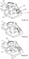
- Figs 20A to 20C show a variant 34' of the second lever 34 viewed in the same direction as Fig. 1A . As can be seen, the magnet 35 has been deleted.
- the second lever 34 is pivotally mounted upon a pivot pin via hole 49'.
- a coil spring 93 has a series of coils 93A (only one of which is shown), a first arm 93B and a second arm 93C.
- the end of first arm 93B is engaged in a hole 94 in the second lever 34'.
- a second arm 93C engages a hole 95 in chassis 18 (drawn schematically).
- the spring is arranged such that the ends of arms 93B and 93C are biased away from each other.
- the ends of arms 93B and 93C initially move towards each other (see Fig.
- the spring 93 fulfils the function of magnet 35 and plate 29 when in the Fig. 20C position and it fulfils the function of second spring 32 when in the Fig. 20A position. As such, variants incorporating the arrangement shown in Figs. 20A to 20C do not require plate 29, magnet 35 or spring 32.
- Figs. 21A to 21C show a variant 34" of the lever 34'.
- the coil spring 93 has been replaced by a compression 96.
- the top 96A of the spring 96 engages either with a first cam surface 97A of lever 34" to hold it in its engaged position as shown in Fig. 21C , or alternatively the top of compression spring 96 engages with a second cam surface 97B to hold the lever 34" in its deactivated position as shown in Fig. 21A .
- the spring 96 is compressed ( Fig. 21B ) and then expands (see Fig. 21C ).
- spring 96 holds the inertia block lever 16 in both the Fig. 21C position when the lever 34" is in its activated position and the spring 96 also holds the lever 34" in the deactivated position as shown in Fig. 21A .
- spring 96 also stops the lever 34" from rattling during normal use of the associated vehicle.
- the inertia event sensor is reset, i.e. it is moved to its deactivated position. In order to do this the force of attraction between the magnet and plate must be overcome.
- the strength of the handle return spring is sufficient alone to move the handle from the Fig. 6B position through the Fig. 7B position through the Fig. 8B position to the rest position as shown in Fig. 1B .
- the handle is simply released it may simply move to the Fig. 7B position and remain there until it is manually pushed to the Fig. 8B position, in order words the handle return spring may not have sufficient force to overcome the force of attraction between the magnet and the plate.
- the inertia of the first lever 44 as it snaps back from the Fig. 5B to the Fig. 6B position may alone be sufficient to overcome the force of attraction between the magnet and the plate. In such an embodiment the first and second levers will move straight from the Fig. 6B position to the rest position as shown in Fig. 1B .
- the magnet is mounted on the second lever 34 and the plate is mounted on the chassis 18.
- the plate could be mounted on the second lever 34 and the magnet could be mounted on the handle chassis.
- various means are used to hold the second lever in its activated position, for example the combination of magnet 35 and plate 29, hook and loop fasteners, a bi-stable spring arrangement as shown in Fig. 20A or a cam arrangement as shown in Fig. 21A . All these arrangements have the advantage that they provide a force which resists movement of the second lever to the deactivated position. This "active" force makes it more likely that the inertia event sensor will function correctly even if there is a momentary change in direction of acceleration during an impact.
- Certain aspects of the present invention utilise magnetic forces and/or magnets. Where such magnets are used in a latch assembly the magnets can attract small particles of steel within the latch. In particular such small particles of steel are creates during riveting processes typically associated with latches. As such, suitable precautions must be taken to ensure that these small pieces of steel do not affect the operation of the latch.
- the outside door handle assembly and the inside door handle assembly are likely to have several plastic components rather than steel components and/or several die cast components (typically die cast in a non-magnetic material). As such there is a lower likelihood of there being small magnetic particles in the outside handle assembly or the inside handle assembly and therefore precautions to protect against such particles may not be required.
- magnets when magnets are used in accordance with the present invention in the transmission path between the outside door handle and the latch, or in the transmission path between the inside door handle and the latch, then typically there is less likelihood of small magnetic particles and as such there is less likelihood of the need for taking precautions against such particles.
Landscapes
- Lock And Its Accessories (AREA)
Claims (15)
- Système de libération de verrou (10, 110) ayant une position de repos et une position d'actionnement et nécessitant une première force (A) pour le déplacer de la position de repos à la position d'actionnement, ce système comprenant un capteur d'effet d'inertie (33, 34, 35, 161, 163) et des moyens (31, 163) permettant d'augmenter la force nécessaire pour faire fonctionner le système,
système dans lequel lorsque le détecteur d'effet d'inertie détecte un effet d'inertie, celui-ci active les moyens (31) de sorte que le système nécessite une seconde force (B) supérieure à la première force pour déplacer le système dans la position d'actionnement. - Système de libération de verrou (10, 110) conforme à la revendication 1,
dans lequel le capteur d'effet d'inertie comporte une masse (33, 34, 35, 161, 163) pouvant être déplacée par rapport au système. - Système de libération de verrou (10) conforme à la revendication 1 ou 2,
dans lequel les moyens sont constitués par des moyens élastiques tels qu'un ressort (31). - Système de libération de verrou (110) conforme à la revendication 1 ou 2,
dans lequel les moyens sont constitués par un aimant (163). - Système de libération de verrou (110) conforme à l'une des revendications 1 à 4,
dans lequel le déplacement du système dans la position d'actionnement désactive les moyens. - Système de libération de verrou (10) conforme à l'une quelconque des revendications 1 à 4,
dans lequel le déplacement du système vers la position de repos désactive les moyens. - Système de libération de verrou (10, 110) conforme à l'une des revendications précédentes,
dans lequel le système a une position intermédiaire (figure 5B) entre la position de repos (figure 1B) et la position d'actionnement (figure 6B) dans laquelle le système de libération de verrou nécessite la seconde force (B) pour déplacer le système de libération de verrou vers la position intermédiaire mais nécessite une troisième force (A) inférieure à la seconde force (B) pour déplacer le système de la position intermédiaire vers la position d'actionnement. - Système de libération de verrou (110) conforme à la revendication 7, lorsqu'elle dépend de l'une quelconque des revendications 1 à 4 dans lequel le déplacement du système au-delà de la position intermédiaire entraîne la désactivation des moyens.
- Système de libération de verrou (10) conforme à la revendication 7, lorsqu'elle dépend de l'une quelconque des revendications 1 à 4, dans lequel le déplacement du système d'une position située entre la position intermédiaire et la position d'actionnement vers la position de repos entraîne la désactivation des moyens.
- Système de libération de verrou (10) conforme à l'une des revendications précédentes, comprenant des moyens de retenue (35, 29) permettant de retenir les moyens (31) dans une position activée.
- Système de libération de verrou (10) conforme à la revendication 10, dans lequel les moyens de retenue exercent une force résistant au déplacement des moyens vers une position désactivée.
- Système de libération de verrou (10) conforme à la revendication 11, dans lequel la force résistant au déplacement des moyens vers une position déterminée est une force magnétique et/ou une force élastique et/ou une force créée par une attache auto-agrippante.
- Système de libération de verrou (10) conforme à l'une quelconque des revendications 10 à 12, dans lequel les moyens de retenue (35, 29) exercent une force rappelant le capteur d'effet d'inertie vers la position activée.
- Système de libération de verrou (10) conforme à la revendication 13, dans lequel la force rappelant le capteur d'effet d'inertie vers la position activée est exercée par une force magnétique et/ou une force élastique.
- Système de libération de verrou (10) conforme à l'une quelconque des revendications précédentes, réalisé sous la forme d'un ensemble de manoeuvre de porte extérieur ou d'un ensemble de manoeuvre de porte intérieur ou d'un ensemble de verrou.
Applications Claiming Priority (2)
| Application Number | Priority Date | Filing Date | Title |
|---|---|---|---|
| GB0818637A GB2464311B (en) | 2008-10-13 | 2008-10-13 | Latch mechanism with inertia event sensor |
| PCT/EP2009/063217 WO2010043573A1 (fr) | 2008-10-13 | 2009-10-09 | Système de libération de verrou |
Publications (2)
| Publication Number | Publication Date |
|---|---|
| EP2334883A1 EP2334883A1 (fr) | 2011-06-22 |
| EP2334883B1 true EP2334883B1 (fr) | 2017-05-03 |
Family
ID=40083858
Family Applications (1)
| Application Number | Title | Priority Date | Filing Date |
|---|---|---|---|
| EP09753054.7A Not-in-force EP2334883B1 (fr) | 2008-10-13 | 2009-10-09 | Système de libération de verrou |
Country Status (6)
| Country | Link |
|---|---|
| US (1) | US9181732B2 (fr) |
| EP (1) | EP2334883B1 (fr) |
| KR (1) | KR101632765B1 (fr) |
| CN (1) | CN102187041B (fr) |
| GB (1) | GB2464311B (fr) |
| WO (1) | WO2010043573A1 (fr) |
Families Citing this family (13)
| Publication number | Priority date | Publication date | Assignee | Title |
|---|---|---|---|---|
| DE102009053553A1 (de) * | 2009-11-18 | 2011-05-19 | Huf Hülsbeck & Fürst Gmbh & Co. Kg | Sicherheitstürgriff |
| KR101543045B1 (ko) | 2010-06-23 | 2015-08-07 | 현대자동차주식회사 | 자동차용 아웃사이드 핸들 구동장치 |
| DE102010049393A1 (de) * | 2010-10-26 | 2012-04-26 | Kiekert Ag | Kraftfahrzeugtürverschluss |
| FR2971283B1 (fr) * | 2011-02-08 | 2013-03-01 | Coutier Moulage Gen Ind | Ensemble de commande d'ouverture d'une porte d'un vehicule |
| DE102011051617A1 (de) * | 2011-07-06 | 2013-01-10 | Huf Hülsbeck & Fürst Gmbh & Co. Kg | Sichere Türgriffeinheit |
| JP5764223B2 (ja) * | 2011-12-28 | 2015-08-12 | 本田技研工業株式会社 | 車両用ドア |
| CN110998049B (zh) * | 2017-05-30 | 2022-03-04 | 布莱特斯帕克产品开发有限责任公司 | 闩锁组件 |
| JP6765351B2 (ja) * | 2017-07-12 | 2020-10-07 | 本田技研工業株式会社 | 車両用ドア構造 |
| CN110043146B (zh) * | 2019-04-18 | 2024-04-12 | 杭州神林电子有限公司 | 一种按压式门锁 |
| EP3760820B1 (fr) * | 2019-07-03 | 2024-12-25 | Minebea AccessSolutions Italia S.p.A. | Poignée électronique destinée à une portière de véhicule et portière de véhicule |
| CN110748250B (zh) * | 2019-10-31 | 2021-01-15 | 江麓机电集团有限公司 | 一种特种车辆载员门锁紧结构 |
| CN112539008A (zh) * | 2020-12-07 | 2021-03-23 | 安徽江淮汽车集团股份有限公司 | 限位装置及汽车 |
| KR20220168314A (ko) * | 2021-06-16 | 2022-12-23 | 엘지전자 주식회사 | 냉장고 |
Citations (1)
| Publication number | Priority date | Publication date | Assignee | Title |
|---|---|---|---|---|
| DE102005043989A1 (de) * | 2005-09-14 | 2007-03-22 | Huf Hülsbeck & Fürst Gmbh & Co. Kg | Betätigungsvorrichtung für ein Schloss |
Family Cites Families (23)
| Publication number | Priority date | Publication date | Assignee | Title |
|---|---|---|---|---|
| DE2023859C3 (de) * | 1970-05-15 | 1978-10-19 | Daimler-Benz Ag, 7000 Stuttgart | Blockiervorrichtung für einen Kraftfahrzeugtürverschluß |
| DE19610200A1 (de) * | 1996-03-15 | 1997-09-18 | Valeo Deutschland Gmbh & Co | Türaußengriff |
| US5669642A (en) * | 1996-06-05 | 1997-09-23 | Hyundai Motor Company | Outside door handle automatic locking device for automobiles |
| US6042159A (en) * | 1997-08-01 | 2000-03-28 | Adac Plastics, Inc. | Door handle assembly |
| DE19756344A1 (de) | 1997-12-18 | 1999-06-24 | Bayerische Motoren Werke Ag | Sicherungseinrichtung an einem Türgriff eines Kraftfahrzeugs |
| DE19910328A1 (de) | 1999-03-09 | 2000-09-14 | Bayerische Motoren Werke Ag | Crashsperre an einem Türgriff oder Türschloß eines Fahrzeugs |
| DE19929022C2 (de) * | 1999-06-25 | 2001-06-07 | Huf Huelsbeck & Fuerst Gmbh | Türaußengriff, insbesondere für Fahrzeuge |
| DE10114583C1 (de) | 2001-03-24 | 2002-12-05 | Huf Huelsbeck & Fuerst Gmbh | Türaußengriff, insbesondere für Fahrzeuge |
| GB0110456D0 (en) * | 2001-04-28 | 2001-06-20 | Meritor Light Vehicle Sys Ltd | Latch assembly |
| GB0113542D0 (en) * | 2001-06-05 | 2001-07-25 | Meritor Light Vehicle Sys Ltd | A mechanism |
| GB0208434D0 (en) * | 2002-04-12 | 2002-05-22 | Meritor Light Vehicle Sys Ltd | Latch arrangement |
| DE102004008048A1 (de) * | 2004-02-19 | 2005-09-08 | Bayerische Motoren Werke Ag | Sperreinrichtung an einer Entriegelungseinrichtung eines Türschlosses an einer Fahrzeugtür |
| US7201405B2 (en) * | 2004-02-23 | 2007-04-10 | Illinois Tool Works Inc. | Inertia-activated mechanism |
| FR2867216B1 (fr) | 2004-03-04 | 2008-01-11 | Peugeot Citroen Automobiles Sa | Dispositif de commande de l'ouverture d'un ouvrant pour un vehicule et vehicule equipe d'un tel dispositif |
| ITRM20040337A1 (it) * | 2004-07-07 | 2004-10-07 | Valeo Sicurezza Abitacolo Spa | Maniglia di portiera, in particolare di autoveicolo, con sistema di sicurezza inerziale. |
| FR2882386B1 (fr) * | 2005-02-18 | 2007-04-06 | Coutier Moulage Gen Ind | Dispositif de commande d'ouverture exterieure d'une serrure de porte de vehicule automobile |
| JP4587942B2 (ja) | 2005-06-30 | 2010-11-24 | 株式会社アルファ | 自動車用ドアハンドル装置 |
| US8038185B2 (en) * | 2005-08-01 | 2011-10-18 | Magna Closures Inc | Locking device |
| DE102007007941A1 (de) | 2007-02-17 | 2008-08-21 | Daimler Ag | Schließeinrichtung für einen Kraftwagen |
| US8282142B2 (en) * | 2008-11-25 | 2012-10-09 | GM Global Technology Operations LLC | Latch release system for a door assembly of a vehicle |
| DE102009038612A1 (de) * | 2009-08-26 | 2011-03-03 | Huf Hülsbeck & Fürst Gmbh & Co. Kg | Griffelement mit einer Crashsperre |
| US8322077B2 (en) * | 2009-11-23 | 2012-12-04 | Ford Global Technologies, Llc | Vehicle door handle with inertia lock mechanism |
| DE102011051617A1 (de) * | 2011-07-06 | 2013-01-10 | Huf Hülsbeck & Fürst Gmbh & Co. Kg | Sichere Türgriffeinheit |
-
2008
- 2008-10-13 GB GB0818637A patent/GB2464311B/en not_active Expired - Fee Related
-
2009
- 2009-10-09 KR KR1020117010663A patent/KR101632765B1/ko not_active Expired - Fee Related
- 2009-10-09 US US13/120,257 patent/US9181732B2/en not_active Expired - Fee Related
- 2009-10-09 EP EP09753054.7A patent/EP2334883B1/fr not_active Not-in-force
- 2009-10-09 WO PCT/EP2009/063217 patent/WO2010043573A1/fr not_active Ceased
- 2009-10-09 CN CN200980140183.4A patent/CN102187041B/zh not_active Expired - Fee Related
Patent Citations (1)
| Publication number | Priority date | Publication date | Assignee | Title |
|---|---|---|---|---|
| DE102005043989A1 (de) * | 2005-09-14 | 2007-03-22 | Huf Hülsbeck & Fürst Gmbh & Co. Kg | Betätigungsvorrichtung für ein Schloss |
Also Published As
| Publication number | Publication date |
|---|---|
| GB2464311A (en) | 2010-04-14 |
| US9181732B2 (en) | 2015-11-10 |
| US20110181058A1 (en) | 2011-07-28 |
| KR20110084234A (ko) | 2011-07-21 |
| WO2010043573A1 (fr) | 2010-04-22 |
| GB0818637D0 (en) | 2008-11-19 |
| CN102187041A (zh) | 2011-09-14 |
| WO2010043573A9 (fr) | 2010-06-24 |
| EP2334883A1 (fr) | 2011-06-22 |
| CN102187041B (zh) | 2014-09-17 |
| KR101632765B1 (ko) | 2016-06-22 |
| GB2464311B (en) | 2012-08-15 |
Similar Documents
| Publication | Publication Date | Title |
|---|---|---|
| EP2334883B1 (fr) | Système de libération de verrou | |
| US8353542B2 (en) | Closure latch with inertia member | |
| US6042159A (en) | Door handle assembly | |
| US6971688B2 (en) | Inertia locking mechanism | |
| US10941592B2 (en) | Latch with double actuation and method of construction thereof | |
| JP6155488B2 (ja) | 複数パーツを備えた爪部を有するロック装置 | |
| JP5746043B2 (ja) | 車両用ドアの開扉制御部用の安全装置 | |
| EP1371799A2 (fr) | Dispositif de verrouillage pour un véhicule automobile | |
| US20160362917A1 (en) | Vehicle hood latch and method of unlatching a vehicle hood | |
| US7532098B2 (en) | Actuator | |
| US8109545B2 (en) | Lock out mechanism for vehicle door outside handles | |
| CN108278053B (zh) | 用于闭合闩锁组件的自由转动惯性机构 | |
| KR20100077163A (ko) | 차량의 도어 래치 시스템 | |
| US9567777B1 (en) | Inertial blocking member subassembly with negative-acceleration inertial blocking member accelerator | |
| EP1355026A2 (fr) | Dispositif de verrouillage | |
| EP1790800A2 (fr) | Dispositif de verrouillage | |
| US20060237973A1 (en) | Momentary inertial latching device | |
| EP1548214A1 (fr) | Mécanisme de verrouillage par inertie | |
| US11414896B2 (en) | Motor vehicle lock | |
| EP1783307A1 (fr) | Dispositif de verrouillage | |
| EP1375793A2 (fr) | Dispositif pour l'ouverture, le verrouillage et le déverrouillage des panneaus d'un véhicule | |
| WO2020230017A1 (fr) | Ensemble formant verrou de fermeture pour véhicules à moteur ayant un mécanisme de résistance à la collision avec levier d'inertie | |
| CZ10180U1 (cs) | Zařízení k zajištění uzávěru kapoty vozidla |
Legal Events
| Date | Code | Title | Description |
|---|---|---|---|
| PUAI | Public reference made under article 153(3) epc to a published international application that has entered the european phase |
Free format text: ORIGINAL CODE: 0009012 |
|
| 17P | Request for examination filed |
Effective date: 20110329 |
|
| AK | Designated contracting states |
Kind code of ref document: A1 Designated state(s): AT BE BG CH CY CZ DE DK EE ES FI FR GB GR HR HU IE IS IT LI LT LU LV MC MK MT NL NO PL PT RO SE SI SK SM TR |
|
| AX | Request for extension of the european patent |
Extension state: AL BA RS |
|
| DAX | Request for extension of the european patent (deleted) | ||
| 17Q | First examination report despatched |
Effective date: 20130124 |
|
| REG | Reference to a national code |
Ref country code: DE Ref legal event code: R079 Ref document number: 602009045861 Country of ref document: DE Free format text: PREVIOUS MAIN CLASS: E05B0065120000 Ipc: E05B0077060000 |
|
| GRAP | Despatch of communication of intention to grant a patent |
Free format text: ORIGINAL CODE: EPIDOSNIGR1 |
|
| RIC1 | Information provided on ipc code assigned before grant |
Ipc: E05B 77/06 20140101AFI20161117BHEP |
|
| INTG | Intention to grant announced |
Effective date: 20161208 |
|
| GRAS | Grant fee paid |
Free format text: ORIGINAL CODE: EPIDOSNIGR3 |
|
| GRAA | (expected) grant |
Free format text: ORIGINAL CODE: 0009210 |
|
| AK | Designated contracting states |
Kind code of ref document: B1 Designated state(s): AT BE BG CH CY CZ DE DK EE ES FI FR GB GR HR HU IE IS IT LI LT LU LV MC MK MT NL NO PL PT RO SE SI SK SM TR |
|
| REG | Reference to a national code |
Ref country code: GB Ref legal event code: FG4D |
|
| REG | Reference to a national code |
Ref country code: AT Ref legal event code: REF Ref document number: 890179 Country of ref document: AT Kind code of ref document: T Effective date: 20170515 Ref country code: CH Ref legal event code: EP |
|
| REG | Reference to a national code |
Ref country code: IE Ref legal event code: FG4D |
|
| REG | Reference to a national code |
Ref country code: DE Ref legal event code: R096 Ref document number: 602009045861 Country of ref document: DE |
|
| REG | Reference to a national code |
Ref country code: NL Ref legal event code: MP Effective date: 20170503 |
|
| REG | Reference to a national code |
Ref country code: AT Ref legal event code: MK05 Ref document number: 890179 Country of ref document: AT Kind code of ref document: T Effective date: 20170503 |
|
| REG | Reference to a national code |
Ref country code: LT Ref legal event code: MG4D |
|
| REG | Reference to a national code |
Ref country code: FR Ref legal event code: PLFP Year of fee payment: 9 |
|
| PG25 | Lapsed in a contracting state [announced via postgrant information from national office to epo] |
Ref country code: LT Free format text: LAPSE BECAUSE OF FAILURE TO SUBMIT A TRANSLATION OF THE DESCRIPTION OR TO PAY THE FEE WITHIN THE PRESCRIBED TIME-LIMIT Effective date: 20170503 Ref country code: ES Free format text: LAPSE BECAUSE OF FAILURE TO SUBMIT A TRANSLATION OF THE DESCRIPTION OR TO PAY THE FEE WITHIN THE PRESCRIBED TIME-LIMIT Effective date: 20170503 Ref country code: FI Free format text: LAPSE BECAUSE OF FAILURE TO SUBMIT A TRANSLATION OF THE DESCRIPTION OR TO PAY THE FEE WITHIN THE PRESCRIBED TIME-LIMIT Effective date: 20170503 Ref country code: AT Free format text: LAPSE BECAUSE OF FAILURE TO SUBMIT A TRANSLATION OF THE DESCRIPTION OR TO PAY THE FEE WITHIN THE PRESCRIBED TIME-LIMIT Effective date: 20170503 Ref country code: GR Free format text: LAPSE BECAUSE OF FAILURE TO SUBMIT A TRANSLATION OF THE DESCRIPTION OR TO PAY THE FEE WITHIN THE PRESCRIBED TIME-LIMIT Effective date: 20170804 Ref country code: NO Free format text: LAPSE BECAUSE OF FAILURE TO SUBMIT A TRANSLATION OF THE DESCRIPTION OR TO PAY THE FEE WITHIN THE PRESCRIBED TIME-LIMIT Effective date: 20170803 Ref country code: HR Free format text: LAPSE BECAUSE OF FAILURE TO SUBMIT A TRANSLATION OF THE DESCRIPTION OR TO PAY THE FEE WITHIN THE PRESCRIBED TIME-LIMIT Effective date: 20170503 |
|
| PG25 | Lapsed in a contracting state [announced via postgrant information from national office to epo] |
Ref country code: IS Free format text: LAPSE BECAUSE OF FAILURE TO SUBMIT A TRANSLATION OF THE DESCRIPTION OR TO PAY THE FEE WITHIN THE PRESCRIBED TIME-LIMIT Effective date: 20170903 Ref country code: PL Free format text: LAPSE BECAUSE OF FAILURE TO SUBMIT A TRANSLATION OF THE DESCRIPTION OR TO PAY THE FEE WITHIN THE PRESCRIBED TIME-LIMIT Effective date: 20170503 Ref country code: NL Free format text: LAPSE BECAUSE OF FAILURE TO SUBMIT A TRANSLATION OF THE DESCRIPTION OR TO PAY THE FEE WITHIN THE PRESCRIBED TIME-LIMIT Effective date: 20170503 Ref country code: SE Free format text: LAPSE BECAUSE OF FAILURE TO SUBMIT A TRANSLATION OF THE DESCRIPTION OR TO PAY THE FEE WITHIN THE PRESCRIBED TIME-LIMIT Effective date: 20170503 Ref country code: LV Free format text: LAPSE BECAUSE OF FAILURE TO SUBMIT A TRANSLATION OF THE DESCRIPTION OR TO PAY THE FEE WITHIN THE PRESCRIBED TIME-LIMIT Effective date: 20170503 Ref country code: BG Free format text: LAPSE BECAUSE OF FAILURE TO SUBMIT A TRANSLATION OF THE DESCRIPTION OR TO PAY THE FEE WITHIN THE PRESCRIBED TIME-LIMIT Effective date: 20170803 |
|
| PG25 | Lapsed in a contracting state [announced via postgrant information from national office to epo] |
Ref country code: RO Free format text: LAPSE BECAUSE OF FAILURE TO SUBMIT A TRANSLATION OF THE DESCRIPTION OR TO PAY THE FEE WITHIN THE PRESCRIBED TIME-LIMIT Effective date: 20170503 Ref country code: EE Free format text: LAPSE BECAUSE OF FAILURE TO SUBMIT A TRANSLATION OF THE DESCRIPTION OR TO PAY THE FEE WITHIN THE PRESCRIBED TIME-LIMIT Effective date: 20170503 Ref country code: SK Free format text: LAPSE BECAUSE OF FAILURE TO SUBMIT A TRANSLATION OF THE DESCRIPTION OR TO PAY THE FEE WITHIN THE PRESCRIBED TIME-LIMIT Effective date: 20170503 Ref country code: CZ Free format text: LAPSE BECAUSE OF FAILURE TO SUBMIT A TRANSLATION OF THE DESCRIPTION OR TO PAY THE FEE WITHIN THE PRESCRIBED TIME-LIMIT Effective date: 20170503 Ref country code: DK Free format text: LAPSE BECAUSE OF FAILURE TO SUBMIT A TRANSLATION OF THE DESCRIPTION OR TO PAY THE FEE WITHIN THE PRESCRIBED TIME-LIMIT Effective date: 20170503 |
|
| REG | Reference to a national code |
Ref country code: DE Ref legal event code: R097 Ref document number: 602009045861 Country of ref document: DE |
|
| PG25 | Lapsed in a contracting state [announced via postgrant information from national office to epo] |
Ref country code: SM Free format text: LAPSE BECAUSE OF FAILURE TO SUBMIT A TRANSLATION OF THE DESCRIPTION OR TO PAY THE FEE WITHIN THE PRESCRIBED TIME-LIMIT Effective date: 20170503 Ref country code: IT Free format text: LAPSE BECAUSE OF FAILURE TO SUBMIT A TRANSLATION OF THE DESCRIPTION OR TO PAY THE FEE WITHIN THE PRESCRIBED TIME-LIMIT Effective date: 20170503 |
|
| PLBE | No opposition filed within time limit |
Free format text: ORIGINAL CODE: 0009261 |
|
| STAA | Information on the status of an ep patent application or granted ep patent |
Free format text: STATUS: NO OPPOSITION FILED WITHIN TIME LIMIT |
|
| 26N | No opposition filed |
Effective date: 20180206 |
|
| PG25 | Lapsed in a contracting state [announced via postgrant information from national office to epo] |
Ref country code: SI Free format text: LAPSE BECAUSE OF FAILURE TO SUBMIT A TRANSLATION OF THE DESCRIPTION OR TO PAY THE FEE WITHIN THE PRESCRIBED TIME-LIMIT Effective date: 20170503 Ref country code: MC Free format text: LAPSE BECAUSE OF FAILURE TO SUBMIT A TRANSLATION OF THE DESCRIPTION OR TO PAY THE FEE WITHIN THE PRESCRIBED TIME-LIMIT Effective date: 20170503 |
|
| REG | Reference to a national code |
Ref country code: CH Ref legal event code: PL |
|
| REG | Reference to a national code |
Ref country code: IE Ref legal event code: MM4A |
|
| PG25 | Lapsed in a contracting state [announced via postgrant information from national office to epo] |
Ref country code: LU Free format text: LAPSE BECAUSE OF NON-PAYMENT OF DUE FEES Effective date: 20171009 Ref country code: LI Free format text: LAPSE BECAUSE OF NON-PAYMENT OF DUE FEES Effective date: 20171031 Ref country code: CH Free format text: LAPSE BECAUSE OF NON-PAYMENT OF DUE FEES Effective date: 20171031 |
|
| REG | Reference to a national code |
Ref country code: BE Ref legal event code: MM Effective date: 20171031 |
|
| PG25 | Lapsed in a contracting state [announced via postgrant information from national office to epo] |
Ref country code: BE Free format text: LAPSE BECAUSE OF NON-PAYMENT OF DUE FEES Effective date: 20171031 |
|
| PG25 | Lapsed in a contracting state [announced via postgrant information from national office to epo] |
Ref country code: MT Free format text: LAPSE BECAUSE OF NON-PAYMENT OF DUE FEES Effective date: 20171009 |
|
| REG | Reference to a national code |
Ref country code: FR Ref legal event code: PLFP Year of fee payment: 10 |
|
| PG25 | Lapsed in a contracting state [announced via postgrant information from national office to epo] |
Ref country code: IE Free format text: LAPSE BECAUSE OF NON-PAYMENT OF DUE FEES Effective date: 20171009 |
|
| PG25 | Lapsed in a contracting state [announced via postgrant information from national office to epo] |
Ref country code: HU Free format text: LAPSE BECAUSE OF FAILURE TO SUBMIT A TRANSLATION OF THE DESCRIPTION OR TO PAY THE FEE WITHIN THE PRESCRIBED TIME-LIMIT; INVALID AB INITIO Effective date: 20091009 |
|
| PG25 | Lapsed in a contracting state [announced via postgrant information from national office to epo] |
Ref country code: CY Free format text: LAPSE BECAUSE OF NON-PAYMENT OF DUE FEES Effective date: 20170503 |
|
| PG25 | Lapsed in a contracting state [announced via postgrant information from national office to epo] |
Ref country code: MK Free format text: LAPSE BECAUSE OF FAILURE TO SUBMIT A TRANSLATION OF THE DESCRIPTION OR TO PAY THE FEE WITHIN THE PRESCRIBED TIME-LIMIT Effective date: 20170503 |
|
| PG25 | Lapsed in a contracting state [announced via postgrant information from national office to epo] |
Ref country code: TR Free format text: LAPSE BECAUSE OF FAILURE TO SUBMIT A TRANSLATION OF THE DESCRIPTION OR TO PAY THE FEE WITHIN THE PRESCRIBED TIME-LIMIT Effective date: 20170503 |
|
| PG25 | Lapsed in a contracting state [announced via postgrant information from national office to epo] |
Ref country code: PT Free format text: LAPSE BECAUSE OF FAILURE TO SUBMIT A TRANSLATION OF THE DESCRIPTION OR TO PAY THE FEE WITHIN THE PRESCRIBED TIME-LIMIT Effective date: 20170503 |
|
| PGFP | Annual fee paid to national office [announced via postgrant information from national office to epo] |
Ref country code: GB Payment date: 20201022 Year of fee payment: 12 Ref country code: DE Payment date: 20201022 Year of fee payment: 12 Ref country code: FR Payment date: 20201020 Year of fee payment: 12 |
|
| REG | Reference to a national code |
Ref country code: DE Ref legal event code: R119 Ref document number: 602009045861 Country of ref document: DE |
|
| GBPC | Gb: european patent ceased through non-payment of renewal fee |
Effective date: 20211009 |
|
| PG25 | Lapsed in a contracting state [announced via postgrant information from national office to epo] |
Ref country code: GB Free format text: LAPSE BECAUSE OF NON-PAYMENT OF DUE FEES Effective date: 20211009 Ref country code: DE Free format text: LAPSE BECAUSE OF NON-PAYMENT OF DUE FEES Effective date: 20220503 |
|
| PG25 | Lapsed in a contracting state [announced via postgrant information from national office to epo] |
Ref country code: FR Free format text: LAPSE BECAUSE OF NON-PAYMENT OF DUE FEES Effective date: 20211031 |