EP2334886B1 - Porte avec fonction d'arrêt - Google Patents
Porte avec fonction d'arrêt Download PDFInfo
- Publication number
- EP2334886B1 EP2334886B1 EP09740644A EP09740644A EP2334886B1 EP 2334886 B1 EP2334886 B1 EP 2334886B1 EP 09740644 A EP09740644 A EP 09740644A EP 09740644 A EP09740644 A EP 09740644A EP 2334886 B1 EP2334886 B1 EP 2334886B1
- Authority
- EP
- European Patent Office
- Prior art keywords
- door
- cam
- holding device
- damping
- door leaf
- Prior art date
- Legal status (The legal status is an assumption and is not a legal conclusion. Google has not performed a legal analysis and makes no representation as to the accuracy of the status listed.)
- Active
Links
Images

Classifications
-
- E—FIXED CONSTRUCTIONS
- E05—LOCKS; KEYS; WINDOW OR DOOR FITTINGS; SAFES
- E05F—DEVICES FOR MOVING WINGS INTO OPEN OR CLOSED POSITION; CHECKS FOR WINGS; WING FITTINGS NOT OTHERWISE PROVIDED FOR, CONCERNED WITH THE FUNCTIONING OF THE WING
- E05F3/00—Closers or openers with braking devices, e.g. checks; Construction of pneumatic or liquid braking devices
- E05F3/22—Additional arrangements for closers, e.g. for holding the wing in opened or other position
- E05F3/221—Mechanical power-locks, e.g. for holding the wing open or for free-moving zones
-
- E—FIXED CONSTRUCTIONS
- E05—LOCKS; KEYS; WINDOW OR DOOR FITTINGS; SAFES
- E05Y—INDEXING SCHEME ASSOCIATED WITH SUBCLASSES E05D AND E05F, RELATING TO CONSTRUCTION ELEMENTS, ELECTRIC CONTROL, POWER SUPPLY, POWER SIGNAL OR TRANSMISSION, USER INTERFACES, MOUNTING OR COUPLING, DETAILS, ACCESSORIES, AUXILIARY OPERATIONS NOT OTHERWISE PROVIDED FOR, APPLICATION THEREOF
- E05Y2900/00—Application of doors, windows, wings or fittings thereof
- E05Y2900/10—Application of doors, windows, wings or fittings thereof for buildings or parts thereof
- E05Y2900/13—Type of wing
- E05Y2900/132—Doors
Definitions
- the invention relates to a door with a built-in mechanism for a door leaf, which is adjustable relative to a door frame between a closed position and an open position, comprising a holding device for the door leaf in its closed position and / or its open position.
- Such a door is for example from the DE 1 036 711 A known and comprises a door leaf which is mounted via a pivot axis on a recessed in a floor mounting housing a mounting mechanism and in the usual manner between a closed position and an open position is adjustable.
- the door leaf undergoes a holding force in its closed position by a spring-loaded roller.
- the roller engages in a latching of a cam, which is formed on the pivot axis of the door leaf.
- the cam has at its periphery a co-operating with the roller rolling surface, which consists of a circular arc-like area in which no closing force acts on the door leaf, a sloping towards the latch curve in which a closing force is exerted by the spring-loaded roller on the door leaf , As well as the rest composed, which defines the closed position of the door leaf.
- the invention has for its object to provide a door of the aforementioned type in a simpler design and with increased functionality.
- the invention thus proposes a door with a door leaf which is adjustable relative to a door frame between a closed position and an open position, comprising a holding device for the door leaf in its closed position and / or open position.
- a connecting lever is arranged, which is hinged at its first end to the door frame and hinged at its second end to the door leaf and carries at one of its two ends a cam having a door holding function in an open position and in the Closed position of the door leaf and cooperates with the holding device.
- the door according to the invention thus forms a provided with a cam connecting lever between the door frame and the door leaf, a control which defines an opening position and the closed position of the door leaf with the cam in cooperation with the holding device, so that the door leaf held in the respective position becomes.
- the connecting lever is pivoted upon actuation of the door, so that the cam undergoes a rotation and the holding device sweeps over the cam surface formed on the circumference of the cam.
- the cam has on its peripheral surface a first, the open position associated detent and a second, the closed position associated detent, between which a circular arc-shaped peripheral region is arranged.
- the cam is thus designed so that when the holding device is applied to the circular arc-shaped peripheral region no opening or closing force or holding force is exerted on the door leaf. Rather, the door leaf undergoes such only upon intervention of the holding device in the first or in the second stop. Due to the circular arc-shaped peripheral region, no automatic door actuation takes place when the holding device is in contact with this area. So there is also no continuous closing process.
- the holding device comprises a setting roller, which is biased in the direction of the cam by means of a spring and is preferably mounted on a spring-loaded piston. Upon pivoting of the door leaf relative to the door frame, the roller rolls off at the circumference of the cam.
- the cam preferably cooperates with a damping device whose effective direction is preferably directed opposite to the actuating roller and which is preferably designed as a damping roller.
- the damping roller is mounted on an oil-damped piston, and they can cooperate to record the damping in the door leaf movement with nose-like projections on the circumference of the cam.
- the door according to the invention is designed, for example, so that the holding device enters during an opening movement of the door leaf at an opening angle of about 70 ° to 95 ° in the first, the open position of the door leaf associated latching of the cam.
- the holding device runs, for example, at an opening angle of the door leaf of about 10 ° to 30 ° in the second stop of the cam.
- the connecting lever is guided in a rail.
- the rail is arranged in the region of the door frame, so that the end hinged to the door frame is guided in the rail.
- the rail can also be formed on the edge side of the door leaf.
- the damping roller and the adjusting roller ie the door leaf-side end of the connecting lever is formed with the cam and the rail for guiding the one end of the connecting lever is also formed on the door leaf, is advantageously a unit of the damping roller and its storage, the actuating roller and the storage and the interposed cam slidably guided in the guide rail.
- the cam engages in an edge-side recess of the door leaf, in which the actuating roller and the damping roller are each arranged with a door leaf-fixed storage.
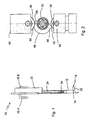
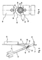
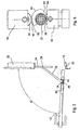
- a door 10 which comprises a door leaf 12 which is about an axis 14 between an in Fig. 1 illustrated closed position of a in Fig. 7 shown opening position is pivotable.
- the door leaf 12 is pivotable relative to a door frame 18, which includes two vertical, the door leaf 12 in the closed position laterally bounding legs 20 and a horizontal, the door leaf 12 in the closed position above limiting leg 22.
- the door leaf 12 on both sides in each case a door handle 16A and 16B.
- the extending in the horizontal direction leg 22 of the door frame 18 has in the region of Zargenquerfalzes a guide or slide rail 24, in which a slider 26 is guided, which is formed at a first end of a connecting lever 28 and via this connecting lever 28 at the door frame 22 is slidably articulated.
- the connecting lever 28 is rotatably connected at its second end facing away from the door frame 22 via a screw 30 with a cam 32 which engages in an edge-side, upper recess 34 of the door panel 12 and in this case between a first, a control roller performing role 36 and a second a damper roller performing role 38 is arranged.
- the actuating roller 36 is rotatably mounted on a biased by a spring, not shown, in the direction of the cam 32 piston 40, which constitutes a drive piston.
- the damping roller 38 is rotatably mounted on an oil-damped piston 42, which constitutes a damping piston.
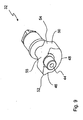
- the cam 32 which in Fig. 9 is shown in isolation, is rotatable about a bearing pin 44 about a substantially vertical axis, which is mounted on a corresponding bearing in the peripheral recess 34 of the door panel 12.
- the cam 32 further has a cam surface which includes a first, the open position associated detent or recess 46, a circular arc-like surface 48, which adjoins the first latch 46, and a second detent or recess 50, the in Fig. 1 assigned closed position is associated and adjoins the circular arc-like surface 48.
- the detents 46 and 50 each pass into a nose-like projection 52 or 54, respectively.
- a rolling surface 55 is arranged for the damping roller 38.
- the nose-like projections 52 and 54 serve respectively for damping the opening or closing movement of the door leaf by cooperating with the damping roller 38, as in FIGS. 4 and 6 can be seen.
- the door shown in the drawing operates in the manner described below.
- the door leaf 12 experiences in an automatic manner until reaching the in Fig. 7 illustrated opening angle of about 107 ° another opening movement.
- the running in the guide rail 24 slider 26 is pressed during the opening operation against a rubber stopper which is slidably fixed in the guide rail 24. It is also conceivable to pivot the door up to an opening angle of about 130 °. In this case, arranged in the guide rail 24 stop or rubber stopper should be moved accordingly. Also, the maximum opening angle of the door panel 12 by a striking of the slider 26 can be specified on the door frame. Then, however, would have to be overcome in the design of the cam 32 shown in the drawing of the adjusting roller 36 of the nose-like projection 52.
- the adjusting roller 36 is in the transition between the circular arc-shaped surface 48 and the detent 50, so that by the bias of the actuating roller 36, which then rolls on a flank of the detent 50, a closing force on the cam 32 and the connecting lever 48 is exerted on the door leaf 12.
- the closing movement triggered thereby is damped by cooperation of the damping roller 38 with the nose-like projection 52.
- the adjusting roller 36 engages in the detent 50 of the cam 32 and is the nose-like projection 52 with its end face on the damping roller 38.
Landscapes
- Engineering & Computer Science (AREA)
- Mechanical Engineering (AREA)
- Closing And Opening Devices For Wings, And Checks For Wings (AREA)
Claims (10)
- Porte comprenant un panneau de porte (12) étant déplaçable par rapport à un châssis de porte (18) entre une position fermée et une position ouverte, comprenant un dispositif de retenue pour le panneau de porte (12) dans la position fermée et/ou ouverte de celui-ci, un levier de liaison (28) étant disposé entre le panneau de porte (12) et le châssis de porte (18), la première extrémité de celui-ci étant reliée de façon articulée au châssis de porte (18) et la seconde extrémité de celui-ci étant reliée de façon articulée au panneau de porte (12) et présentant une came (32) sur l'une des deux extrémités de celui-ci, ladite came ayant une fonction de retenue pour la porte dans une position ouverte et une position fermée du panneau de porte (12) et interagissant avec le dispositif der retenue,
caractérisée en ce que
sur la surface circonférentielle de celui-ci la came (32) présente un premier élément d'encliquetage (46) étant attribué à la position ouverte, et un second élément d'encliquetage (50) étant attribué à la position fermée, une zone circonférentielle (48) en forme d'arc de cercle étant disposée entre les deux éléments d'encliquetage, le second élément d'encliquetage (50) fusionnant dans une première saillie (54) en forme de bec sur le côté détourné de la zone circonférentielle (48) en forme d'arc de cercle servant pour l'amortissement du mouvement d'ouverture par l'interaction avec un dispositif amortisseur (38), la direction d'actionnement du dispositif amortisseur étant opposée au dispositif de retenue (38), et le premier élément d'encliquetage (46) fusionnant dans une seconde saillie (52) en forme de bec sur le côté détourné de la zone circonférentielle en forme d'arc de cercle servant pour l'amortissement du mouvement de fermeture par l'interaction avec le dispositif amortisseur (38). - Porte selon la revendication 1,
caractérisée en ce que
le dispositif de retenue comprend un levier de réglage (36) étant précontraint dans la direction de la came (32) à l'aide d'un ressort et de préference est monté sur un piston (40) étant chargé par ressort. - Porte selon l'une quelconque des revendications 1 ou 2,
caractérisée en ce que
le dispositif amortisseur (38) est conçu en tant qu'un rouleau amortisseur. - Porte selon la revendication 3,
caractérisée en ce que
le dispositif amortisseur (38) est monté sur un piston (42) amortisseur à l'huile. - Porte selon la revendication 1,
caractérisée en ce que
le dispositif de retenue entre dans le premier élément d'encliquetage (46) de la came (32) lorsque le panneau de porte (12) exécute un mouvement d'ouverture avec un angle d'ouverture d'environ 70° à 95°. - Porte selon la revendication 1,
caractérisée en ce que
le dispositif de retenue entre dans le second élément d'encliquetage (50) de la came (32) lorsque le panneau de porte (12) exécute un mouvementa de fermeture avec un angle d'ouverture d'environ 10° à 30°. - Porte selon l'une quelconque des revendications 1 à 6,
caractérisée en ce qu'
au moins une extrémité du levier de liaison (28) est guidée dans un rail (24). - Porte selon la revendication 7,
caractérisée en ce que
l'extrémité du levier de liaison (28) étant reliée de façon articulée au châssis de porte (22) est guidée dans le rail (24). - Porte selon la revendication 7,
caractérisée en ce que
l'extrémité du levier de liaison reliée de façon articulée au le panneau de porte est guidée dans le rail. - Porte selon l'une quelconque des revendications 1 à 9,
caractérisée en ce que
la came (32) vient s'engrener dans un évidement (34) disposé du côté du bord dans lequel le dispositif de retenue est logé.
Applications Claiming Priority (2)
| Application Number | Priority Date | Filing Date | Title |
|---|---|---|---|
| DE200820013579 DE202008013579U1 (de) | 2008-10-13 | 2008-10-13 | Tür mit Haltefunktion |
| PCT/EP2009/007006 WO2010043308A1 (fr) | 2008-10-13 | 2009-09-29 | Porte avec fonction d'arrêt |
Publications (2)
| Publication Number | Publication Date |
|---|---|
| EP2334886A1 EP2334886A1 (fr) | 2011-06-22 |
| EP2334886B1 true EP2334886B1 (fr) | 2012-11-07 |
Family
ID=40149522
Family Applications (1)
| Application Number | Title | Priority Date | Filing Date |
|---|---|---|---|
| EP09740644A Active EP2334886B1 (fr) | 2008-10-13 | 2009-09-29 | Porte avec fonction d'arrêt |
Country Status (3)
| Country | Link |
|---|---|
| EP (1) | EP2334886B1 (fr) |
| DE (1) | DE202008013579U1 (fr) |
| WO (1) | WO2010043308A1 (fr) |
Family Cites Families (5)
| Publication number | Priority date | Publication date | Assignee | Title |
|---|---|---|---|---|
| US1678511A (en) * | 1926-05-26 | 1928-07-24 | David O Young Narme | Stay for casement windows and the like |
| DE1036711B (de) | 1954-04-08 | 1958-08-14 | Ver Baubeschlag Gretsch Co | Schliesser fuer die Fluegel von Tueren, insbesondere Bodentuerschliesser |
| DE3033496C2 (de) * | 1980-09-05 | 1985-07-25 | Casma di V. Marinoni & Figli, Magenta | In Offenstellung verrastbares Türschließergestänge |
| US5417013A (en) * | 1992-07-10 | 1995-05-23 | Dorma Gmbh + Co. Kg | Overhead door closer with slide rail for concealed installation in door panels or door frames |
| AUPS001402A0 (en) * | 2002-01-18 | 2002-02-07 | Kral, Joseph Michael | Mechanical door closer |
-
2008
- 2008-10-13 DE DE200820013579 patent/DE202008013579U1/de not_active Expired - Lifetime
-
2009
- 2009-09-29 EP EP09740644A patent/EP2334886B1/fr active Active
- 2009-09-29 WO PCT/EP2009/007006 patent/WO2010043308A1/fr not_active Ceased
Also Published As
| Publication number | Publication date |
|---|---|
| EP2334886A1 (fr) | 2011-06-22 |
| DE202008013579U1 (de) | 2008-12-18 |
| WO2010043308A1 (fr) | 2010-04-22 |
Similar Documents
| Publication | Publication Date | Title |
|---|---|---|
| DE202004021727U1 (de) | Scharnier | |
| EP3307111B1 (fr) | Dispositif d'éjection d'un élément de meuble mobile | |
| EP2762660A2 (fr) | Gâche de logement d'un pêne | |
| EP3004504B1 (fr) | Ferme-porte pour un vantail de porte ou de fenetre | |
| WO2022082238A1 (fr) | Dispositif d'entraînement pour une partie de meuble mobile | |
| DE3612917C2 (fr) | ||
| EP3675691B1 (fr) | Dispositif d'insertion permettant d'insérer une partie mobile d'un meuble ou d'un appareil ménager dans une position finale | |
| EP2843169B1 (fr) | Porte coulissante avec système de support | |
| DE10152699B4 (de) | Möbelscharnier mit Öffnungsmechanik, insbesondere für Möbeltüren | |
| EP2334886B1 (fr) | Porte avec fonction d'arrêt | |
| WO2015010672A1 (fr) | Dispositif permettant de déclencher un ressort à gaz | |
| EP3109385A1 (fr) | Dispositif de fermeture de porte comprenant un battant de porte unique ou en plusieurs parties | |
| DE19545402A1 (de) | Schließfolgesteuerung für eine automatisch schließende, zweiflügelige Tür | |
| EP2597234A2 (fr) | Dispositif d'arrêt d'une porte, de préférence avec ferme-porte | |
| EP4573251A1 (fr) | Dispositif de décalage permettant le décalage forcé d'un battant, en particulier d'un battant coulissant, d'une fenêtre ou d'une porte | |
| EP1959076B1 (fr) | Automate de fermeture pour un battant de porte ou de fenêtre | |
| DE20122827U1 (de) | Möbelscharnier mit Öffnungsmechanik, insbesondere für Möbeltüren | |
| EP2811095A1 (fr) | Ferme-porte pour un vantail d'une porte ou d'une fenêtre | |
| DE102016123484B3 (de) | Türschließer | |
| EP2148028B1 (fr) | Organe de verrouillage pour portes | |
| EP3985219B1 (fr) | Agencement doté d'un joint d'étanchéité de plancher pour une porte, un espace intermédiaire se trouvant entre un battant de porte et un cadre, dans lequel passe le seul axe de rotation du battant | |
| DE102012213782B4 (de) | Verlagerungsanordnung zur Verlagerung eines Schiebeflügels eines Fensters, einer Tür oder dergleichen relativ zu einer festen Einfassung mit einem flügelseitigen und einem einfassungsseitigen Steuerelement | |
| DE102013000969B4 (de) | Schließfolgeregelungseinrichtung für eine zweiflügelige Tür | |
| DE202016103018U1 (de) | Türanordnung mit Einbaumechanik | |
| DE202007002265U1 (de) | Schließautomat für einen Tür- oder Fensterflügel |
Legal Events
| Date | Code | Title | Description |
|---|---|---|---|
| PUAI | Public reference made under article 153(3) epc to a published international application that has entered the european phase |
Free format text: ORIGINAL CODE: 0009012 |
|
| 17P | Request for examination filed |
Effective date: 20110222 |
|
| AK | Designated contracting states |
Kind code of ref document: A1 Designated state(s): AT BE BG CH CY CZ DE DK EE ES FI FR GB GR HR HU IE IS IT LI LT LU LV MC MK MT NL NO PL PT RO SE SI SK SM TR |
|
| AX | Request for extension of the european patent |
Extension state: AL BA RS |
|
| DAX | Request for extension of the european patent (deleted) | ||
| GRAP | Despatch of communication of intention to grant a patent |
Free format text: ORIGINAL CODE: EPIDOSNIGR1 |
|
| GRAJ | Information related to disapproval of communication of intention to grant by the applicant or resumption of examination proceedings by the epo deleted |
Free format text: ORIGINAL CODE: EPIDOSDIGR1 |
|
| GRAS | Grant fee paid |
Free format text: ORIGINAL CODE: EPIDOSNIGR3 |
|
| RIC1 | Information provided on ipc code assigned before grant |
Ipc: E05F 3/22 20060101AFI20120711BHEP |
|
| GRAP | Despatch of communication of intention to grant a patent |
Free format text: ORIGINAL CODE: EPIDOSNIGR1 |
|
| GRAA | (expected) grant |
Free format text: ORIGINAL CODE: 0009210 |
|
| AK | Designated contracting states |
Kind code of ref document: B1 Designated state(s): AT BE BG CH CY CZ DE DK EE ES FI FR GB GR HR HU IE IS IT LI LT LU LV MC MK MT NL NO PL PT RO SE SI SK SM TR |
|
| REG | Reference to a national code |
Ref country code: GB Ref legal event code: FG4D Free format text: NOT ENGLISH |
|
| REG | Reference to a national code |
Ref country code: CH Ref legal event code: EP Ref country code: AT Ref legal event code: REF Ref document number: 583095 Country of ref document: AT Kind code of ref document: T Effective date: 20121115 |
|
| REG | Reference to a national code |
Ref country code: IE Ref legal event code: FG4D Free format text: LANGUAGE OF EP DOCUMENT: GERMAN |
|
| REG | Reference to a national code |
Ref country code: CH Ref legal event code: NV Representative=s name: E. BLUM AND CO. AG PATENT- UND MARKENANWAELTE , CH |
|
| REG | Reference to a national code |
Ref country code: DE Ref legal event code: R096 Ref document number: 502009005317 Country of ref document: DE Effective date: 20130103 |
|
| REG | Reference to a national code |
Ref country code: NL Ref legal event code: VDEP Effective date: 20121107 |
|
| REG | Reference to a national code |
Ref country code: LT Ref legal event code: MG4D |
|
| PG25 | Lapsed in a contracting state [announced via postgrant information from national office to epo] |
Ref country code: NL Free format text: LAPSE BECAUSE OF FAILURE TO SUBMIT A TRANSLATION OF THE DESCRIPTION OR TO PAY THE FEE WITHIN THE PRESCRIBED TIME-LIMIT Effective date: 20121107 Ref country code: LT Free format text: LAPSE BECAUSE OF FAILURE TO SUBMIT A TRANSLATION OF THE DESCRIPTION OR TO PAY THE FEE WITHIN THE PRESCRIBED TIME-LIMIT Effective date: 20121107 Ref country code: IS Free format text: LAPSE BECAUSE OF FAILURE TO SUBMIT A TRANSLATION OF THE DESCRIPTION OR TO PAY THE FEE WITHIN THE PRESCRIBED TIME-LIMIT Effective date: 20130307 Ref country code: HR Free format text: LAPSE BECAUSE OF FAILURE TO SUBMIT A TRANSLATION OF THE DESCRIPTION OR TO PAY THE FEE WITHIN THE PRESCRIBED TIME-LIMIT Effective date: 20121107 Ref country code: NO Free format text: LAPSE BECAUSE OF FAILURE TO SUBMIT A TRANSLATION OF THE DESCRIPTION OR TO PAY THE FEE WITHIN THE PRESCRIBED TIME-LIMIT Effective date: 20130207 Ref country code: SE Free format text: LAPSE BECAUSE OF FAILURE TO SUBMIT A TRANSLATION OF THE DESCRIPTION OR TO PAY THE FEE WITHIN THE PRESCRIBED TIME-LIMIT Effective date: 20121107 Ref country code: FI Free format text: LAPSE BECAUSE OF FAILURE TO SUBMIT A TRANSLATION OF THE DESCRIPTION OR TO PAY THE FEE WITHIN THE PRESCRIBED TIME-LIMIT Effective date: 20121107 |
|
| PG25 | Lapsed in a contracting state [announced via postgrant information from national office to epo] |
Ref country code: GR Free format text: LAPSE BECAUSE OF FAILURE TO SUBMIT A TRANSLATION OF THE DESCRIPTION OR TO PAY THE FEE WITHIN THE PRESCRIBED TIME-LIMIT Effective date: 20130208 Ref country code: PL Free format text: LAPSE BECAUSE OF FAILURE TO SUBMIT A TRANSLATION OF THE DESCRIPTION OR TO PAY THE FEE WITHIN THE PRESCRIBED TIME-LIMIT Effective date: 20121107 Ref country code: LV Free format text: LAPSE BECAUSE OF FAILURE TO SUBMIT A TRANSLATION OF THE DESCRIPTION OR TO PAY THE FEE WITHIN THE PRESCRIBED TIME-LIMIT Effective date: 20121107 Ref country code: SI Free format text: LAPSE BECAUSE OF FAILURE TO SUBMIT A TRANSLATION OF THE DESCRIPTION OR TO PAY THE FEE WITHIN THE PRESCRIBED TIME-LIMIT Effective date: 20121107 Ref country code: PT Free format text: LAPSE BECAUSE OF FAILURE TO SUBMIT A TRANSLATION OF THE DESCRIPTION OR TO PAY THE FEE WITHIN THE PRESCRIBED TIME-LIMIT Effective date: 20130307 |
|
| PG25 | Lapsed in a contracting state [announced via postgrant information from national office to epo] |
Ref country code: SK Free format text: LAPSE BECAUSE OF FAILURE TO SUBMIT A TRANSLATION OF THE DESCRIPTION OR TO PAY THE FEE WITHIN THE PRESCRIBED TIME-LIMIT Effective date: 20121107 Ref country code: BG Free format text: LAPSE BECAUSE OF FAILURE TO SUBMIT A TRANSLATION OF THE DESCRIPTION OR TO PAY THE FEE WITHIN THE PRESCRIBED TIME-LIMIT Effective date: 20130207 Ref country code: CZ Free format text: LAPSE BECAUSE OF FAILURE TO SUBMIT A TRANSLATION OF THE DESCRIPTION OR TO PAY THE FEE WITHIN THE PRESCRIBED TIME-LIMIT Effective date: 20121107 Ref country code: EE Free format text: LAPSE BECAUSE OF FAILURE TO SUBMIT A TRANSLATION OF THE DESCRIPTION OR TO PAY THE FEE WITHIN THE PRESCRIBED TIME-LIMIT Effective date: 20121107 Ref country code: DK Free format text: LAPSE BECAUSE OF FAILURE TO SUBMIT A TRANSLATION OF THE DESCRIPTION OR TO PAY THE FEE WITHIN THE PRESCRIBED TIME-LIMIT Effective date: 20121107 |
|
| PG25 | Lapsed in a contracting state [announced via postgrant information from national office to epo] |
Ref country code: RO Free format text: LAPSE BECAUSE OF FAILURE TO SUBMIT A TRANSLATION OF THE DESCRIPTION OR TO PAY THE FEE WITHIN THE PRESCRIBED TIME-LIMIT Effective date: 20121107 Ref country code: IT Free format text: LAPSE BECAUSE OF FAILURE TO SUBMIT A TRANSLATION OF THE DESCRIPTION OR TO PAY THE FEE WITHIN THE PRESCRIBED TIME-LIMIT Effective date: 20121107 |
|
| PLBE | No opposition filed within time limit |
Free format text: ORIGINAL CODE: 0009261 |
|
| STAA | Information on the status of an ep patent application or granted ep patent |
Free format text: STATUS: NO OPPOSITION FILED WITHIN TIME LIMIT |
|
| 26N | No opposition filed |
Effective date: 20130808 |
|
| PG25 | Lapsed in a contracting state [announced via postgrant information from national office to epo] |
Ref country code: ES Free format text: LAPSE BECAUSE OF FAILURE TO SUBMIT A TRANSLATION OF THE DESCRIPTION OR TO PAY THE FEE WITHIN THE PRESCRIBED TIME-LIMIT Effective date: 20130218 |
|
| PG25 | Lapsed in a contracting state [announced via postgrant information from national office to epo] |
Ref country code: CY Free format text: LAPSE BECAUSE OF FAILURE TO SUBMIT A TRANSLATION OF THE DESCRIPTION OR TO PAY THE FEE WITHIN THE PRESCRIBED TIME-LIMIT Effective date: 20121107 |
|
| REG | Reference to a national code |
Ref country code: DE Ref legal event code: R097 Ref document number: 502009005317 Country of ref document: DE Effective date: 20130808 |
|
| BERE | Be: lapsed |
Owner name: JELD-WEN TUREN GMBH Effective date: 20130930 |
|
| PG25 | Lapsed in a contracting state [announced via postgrant information from national office to epo] |
Ref country code: MC Free format text: LAPSE BECAUSE OF FAILURE TO SUBMIT A TRANSLATION OF THE DESCRIPTION OR TO PAY THE FEE WITHIN THE PRESCRIBED TIME-LIMIT Effective date: 20121107 |
|
| REG | Reference to a national code |
Ref country code: IE Ref legal event code: MM4A |
|
| PG25 | Lapsed in a contracting state [announced via postgrant information from national office to epo] |
Ref country code: IE Free format text: LAPSE BECAUSE OF NON-PAYMENT OF DUE FEES Effective date: 20130929 Ref country code: BE Free format text: LAPSE BECAUSE OF NON-PAYMENT OF DUE FEES Effective date: 20130930 |
|
| PG25 | Lapsed in a contracting state [announced via postgrant information from national office to epo] |
Ref country code: SM Free format text: LAPSE BECAUSE OF FAILURE TO SUBMIT A TRANSLATION OF THE DESCRIPTION OR TO PAY THE FEE WITHIN THE PRESCRIBED TIME-LIMIT Effective date: 20121107 |
|
| PG25 | Lapsed in a contracting state [announced via postgrant information from national office to epo] |
Ref country code: MT Free format text: LAPSE BECAUSE OF FAILURE TO SUBMIT A TRANSLATION OF THE DESCRIPTION OR TO PAY THE FEE WITHIN THE PRESCRIBED TIME-LIMIT Effective date: 20121107 Ref country code: TR Free format text: LAPSE BECAUSE OF FAILURE TO SUBMIT A TRANSLATION OF THE DESCRIPTION OR TO PAY THE FEE WITHIN THE PRESCRIBED TIME-LIMIT Effective date: 20121107 |
|
| PG25 | Lapsed in a contracting state [announced via postgrant information from national office to epo] |
Ref country code: MK Free format text: LAPSE BECAUSE OF FAILURE TO SUBMIT A TRANSLATION OF THE DESCRIPTION OR TO PAY THE FEE WITHIN THE PRESCRIBED TIME-LIMIT Effective date: 20121107 Ref country code: LU Free format text: LAPSE BECAUSE OF NON-PAYMENT OF DUE FEES Effective date: 20130929 Ref country code: HU Free format text: LAPSE BECAUSE OF FAILURE TO SUBMIT A TRANSLATION OF THE DESCRIPTION OR TO PAY THE FEE WITHIN THE PRESCRIBED TIME-LIMIT; INVALID AB INITIO Effective date: 20090929 |
|
| REG | Reference to a national code |
Ref country code: FR Ref legal event code: PLFP Year of fee payment: 8 |
|
| REG | Reference to a national code |
Ref country code: FR Ref legal event code: PLFP Year of fee payment: 9 |
|
| REG | Reference to a national code |
Ref country code: FR Ref legal event code: PLFP Year of fee payment: 10 |
|
| REG | Reference to a national code |
Ref country code: DE Ref legal event code: R082 Ref document number: 502009005317 Country of ref document: DE Representative=s name: LKGLOBAL LORENZ UND KOPF PATENTANWALT, ATTORNE, DE Ref country code: DE Ref legal event code: R082 Ref document number: 502009005317 Country of ref document: DE Representative=s name: LKGLOBAL | LORENZ & KOPF PARTG MBB PATENTANWAE, DE Ref country code: DE Ref legal event code: R082 Ref document number: 502009005317 Country of ref document: DE Representative=s name: BALDER IP LAW, S.L., ES |
|
| P01 | Opt-out of the competence of the unified patent court (upc) registered |
Effective date: 20230518 |
|
| REG | Reference to a national code |
Ref country code: DE Ref legal event code: R082 Ref document number: 502009005317 Country of ref document: DE Representative=s name: BALDER IP LAW, S.L., ES Ref country code: DE Ref legal event code: R081 Ref document number: 502009005317 Country of ref document: DE Owner name: DORMAKABA DEUTSCHLAND GMBH, DE Free format text: FORMER OWNER: JELD-WEN TUEREN GMBH, SPITAL AM PYHRN, AT |
|
| REG | Reference to a national code |
Ref country code: AT Ref legal event code: PC Ref document number: 583095 Country of ref document: AT Kind code of ref document: T Owner name: DORMAKABA DEUTSCHLAND GMBH, DE Effective date: 20241210 |
|
| REG | Reference to a national code |
Ref country code: CH Ref legal event code: U11 Free format text: ST27 STATUS EVENT CODE: U-0-0-U10-U11 (AS PROVIDED BY THE NATIONAL OFFICE) Effective date: 20251001 |
|
| PGFP | Annual fee paid to national office [announced via postgrant information from national office to epo] |
Ref country code: DE Payment date: 20250919 Year of fee payment: 17 |
|
| PGFP | Annual fee paid to national office [announced via postgrant information from national office to epo] |
Ref country code: GB Payment date: 20250918 Year of fee payment: 17 |
|
| PGFP | Annual fee paid to national office [announced via postgrant information from national office to epo] |
Ref country code: FR Payment date: 20250922 Year of fee payment: 17 Ref country code: AT Payment date: 20250919 Year of fee payment: 17 |
|
| PGFP | Annual fee paid to national office [announced via postgrant information from national office to epo] |
Ref country code: CH Payment date: 20251001 Year of fee payment: 17 |