EP2335546B1 - Dispositif de nettoyage doté d'un élément d'actionnement - Google Patents
Dispositif de nettoyage doté d'un élément d'actionnement Download PDFInfo
- Publication number
- EP2335546B1 EP2335546B1 EP10014760.2A EP10014760A EP2335546B1 EP 2335546 B1 EP2335546 B1 EP 2335546B1 EP 10014760 A EP10014760 A EP 10014760A EP 2335546 B1 EP2335546 B1 EP 2335546B1
- Authority
- EP
- European Patent Office
- Prior art keywords
- sensor
- cleaning
- cleaning apparatus
- washware
- inlet
- Prior art date
- Legal status (The legal status is an assumption and is not a legal conclusion. Google has not performed a legal analysis and makes no representation as to the accuracy of the status listed.)
- Not-in-force
Links
- 238000004140 cleaning Methods 0.000 title claims description 170
- 239000012530 fluid Substances 0.000 claims description 17
- 238000000034 method Methods 0.000 claims description 15
- 230000003287 optical effect Effects 0.000 claims description 5
- 230000004888 barrier function Effects 0.000 claims description 4
- 239000013505 freshwater Substances 0.000 description 19
- 239000011538 cleaning material Substances 0.000 description 13
- 238000001514 detection method Methods 0.000 description 10
- 239000007921 spray Substances 0.000 description 9
- 230000008859 change Effects 0.000 description 5
- 230000005540 biological transmission Effects 0.000 description 4
- 238000006243 chemical reaction Methods 0.000 description 4
- 230000002000 scavenging effect Effects 0.000 description 4
- XLYOFNOQVPJJNP-UHFFFAOYSA-N water Substances O XLYOFNOQVPJJNP-UHFFFAOYSA-N 0.000 description 4
- 238000005253 cladding Methods 0.000 description 3
- 238000001035 drying Methods 0.000 description 3
- 239000002184 metal Substances 0.000 description 3
- 241000792859 Enema Species 0.000 description 2
- 230000009977 dual effect Effects 0.000 description 2
- 230000000694 effects Effects 0.000 description 2
- 239000007920 enema Substances 0.000 description 2
- 229940095399 enema Drugs 0.000 description 2
- 235000013305 food Nutrition 0.000 description 2
- 238000009434 installation Methods 0.000 description 2
- 238000011084 recovery Methods 0.000 description 2
- 230000000630 rising effect Effects 0.000 description 2
- 238000004659 sterilization and disinfection Methods 0.000 description 2
- 235000014676 Phragmites communis Nutrition 0.000 description 1
- 238000010276 construction Methods 0.000 description 1
- 230000008878 coupling Effects 0.000 description 1
- 238000010168 coupling process Methods 0.000 description 1
- 238000005859 coupling reaction Methods 0.000 description 1
- 230000001419 dependent effect Effects 0.000 description 1
- 238000011161 development Methods 0.000 description 1
- 230000018109 developmental process Effects 0.000 description 1
- 239000010794 food waste Substances 0.000 description 1
- 239000011521 glass Substances 0.000 description 1
- 238000011086 high cleaning Methods 0.000 description 1
- 239000012535 impurity Substances 0.000 description 1
- 239000007788 liquid Substances 0.000 description 1
- 239000012528 membrane Substances 0.000 description 1
- 238000002360 preparation method Methods 0.000 description 1
- 230000008569 process Effects 0.000 description 1
- 230000000284 resting effect Effects 0.000 description 1
- 230000008054 signal transmission Effects 0.000 description 1
- 230000001954 sterilising effect Effects 0.000 description 1
- 239000000725 suspension Substances 0.000 description 1
- 238000005406 washing Methods 0.000 description 1
Images

Classifications
-
- A—HUMAN NECESSITIES
- A47—FURNITURE; DOMESTIC ARTICLES OR APPLIANCES; COFFEE MILLS; SPICE MILLS; SUCTION CLEANERS IN GENERAL
- A47L—DOMESTIC WASHING OR CLEANING; SUCTION CLEANERS IN GENERAL
- A47L15/00—Washing or rinsing machines for crockery or tableware
- A47L15/0018—Controlling processes, i.e. processes to control the operation of the machine characterised by the purpose or target of the control
- A47L15/0049—Detection or prevention of malfunction, including accident prevention
-
- A—HUMAN NECESSITIES
- A47—FURNITURE; DOMESTIC ARTICLES OR APPLIANCES; COFFEE MILLS; SPICE MILLS; SUCTION CLEANERS IN GENERAL
- A47L—DOMESTIC WASHING OR CLEANING; SUCTION CLEANERS IN GENERAL
- A47L15/00—Washing or rinsing machines for crockery or tableware
- A47L15/24—Washing or rinsing machines for crockery or tableware with movement of the crockery baskets by conveyors
- A47L15/247—Details specific to conveyor-type machines, e.g. curtains
-
- A—HUMAN NECESSITIES
- A47—FURNITURE; DOMESTIC ARTICLES OR APPLIANCES; COFFEE MILLS; SPICE MILLS; SUCTION CLEANERS IN GENERAL
- A47L—DOMESTIC WASHING OR CLEANING; SUCTION CLEANERS IN GENERAL
- A47L2301/00—Manual input in controlling methods of washing or rinsing machines for crockery or tableware, i.e. information entered by a user
- A47L2301/08—Other manual input
-
- A—HUMAN NECESSITIES
- A47—FURNITURE; DOMESTIC ARTICLES OR APPLIANCES; COFFEE MILLS; SPICE MILLS; SUCTION CLEANERS IN GENERAL
- A47L—DOMESTIC WASHING OR CLEANING; SUCTION CLEANERS IN GENERAL
- A47L2401/00—Automatic detection in controlling methods of washing or rinsing machines for crockery or tableware, e.g. information provided by sensors entered into controlling devices
- A47L2401/04—Crockery or tableware details, e.g. material, quantity, condition
-
- A—HUMAN NECESSITIES
- A47—FURNITURE; DOMESTIC ARTICLES OR APPLIANCES; COFFEE MILLS; SPICE MILLS; SUCTION CLEANERS IN GENERAL
- A47L—DOMESTIC WASHING OR CLEANING; SUCTION CLEANERS IN GENERAL
- A47L2401/00—Automatic detection in controlling methods of washing or rinsing machines for crockery or tableware, e.g. information provided by sensors entered into controlling devices
- A47L2401/30—Variation of electrical, magnetical or optical quantities
-
- A—HUMAN NECESSITIES
- A47—FURNITURE; DOMESTIC ARTICLES OR APPLIANCES; COFFEE MILLS; SPICE MILLS; SUCTION CLEANERS IN GENERAL
- A47L—DOMESTIC WASHING OR CLEANING; SUCTION CLEANERS IN GENERAL
- A47L2401/00—Automatic detection in controlling methods of washing or rinsing machines for crockery or tableware, e.g. information provided by sensors entered into controlling devices
- A47L2401/34—Other automatic detections
-
- A—HUMAN NECESSITIES
- A47—FURNITURE; DOMESTIC ARTICLES OR APPLIANCES; COFFEE MILLS; SPICE MILLS; SUCTION CLEANERS IN GENERAL
- A47L—DOMESTIC WASHING OR CLEANING; SUCTION CLEANERS IN GENERAL
- A47L2501/00—Output in controlling method of washing or rinsing machines for crockery or tableware, i.e. quantities or components controlled, or actions performed by the controlling device executing the controlling method
- A47L2501/05—Drain or recirculation pump, e.g. regulation of the pump rotational speed or flow direction
-
- A—HUMAN NECESSITIES
- A47—FURNITURE; DOMESTIC ARTICLES OR APPLIANCES; COFFEE MILLS; SPICE MILLS; SUCTION CLEANERS IN GENERAL
- A47L—DOMESTIC WASHING OR CLEANING; SUCTION CLEANERS IN GENERAL
- A47L2501/00—Output in controlling method of washing or rinsing machines for crockery or tableware, i.e. quantities or components controlled, or actions performed by the controlling device executing the controlling method
- A47L2501/12—Air blowers
-
- A—HUMAN NECESSITIES
- A47—FURNITURE; DOMESTIC ARTICLES OR APPLIANCES; COFFEE MILLS; SPICE MILLS; SUCTION CLEANERS IN GENERAL
- A47L—DOMESTIC WASHING OR CLEANING; SUCTION CLEANERS IN GENERAL
- A47L2501/00—Output in controlling method of washing or rinsing machines for crockery or tableware, i.e. quantities or components controlled, or actions performed by the controlling device executing the controlling method
- A47L2501/24—Conveyor belts, e.g. conveyor belts motors
-
- A—HUMAN NECESSITIES
- A47—FURNITURE; DOMESTIC ARTICLES OR APPLIANCES; COFFEE MILLS; SPICE MILLS; SUCTION CLEANERS IN GENERAL
- A47L—DOMESTIC WASHING OR CLEANING; SUCTION CLEANERS IN GENERAL
- A47L2501/00—Output in controlling method of washing or rinsing machines for crockery or tableware, i.e. quantities or components controlled, or actions performed by the controlling device executing the controlling method
- A47L2501/26—Indication or alarm to the controlling device or to the user
-
- A—HUMAN NECESSITIES
- A47—FURNITURE; DOMESTIC ARTICLES OR APPLIANCES; COFFEE MILLS; SPICE MILLS; SUCTION CLEANERS IN GENERAL
- A47L—DOMESTIC WASHING OR CLEANING; SUCTION CLEANERS IN GENERAL
- A47L2501/00—Output in controlling method of washing or rinsing machines for crockery or tableware, i.e. quantities or components controlled, or actions performed by the controlling device executing the controlling method
- A47L2501/32—Stopping or disabling machine operation, including disconnecting the machine from a network, e.g. from an electrical power supply
Definitions
- the invention relates to a cleaning device in which a sensor is used in a dual function once for the detection of items to be cleaned and on the other for the transmission of control commands. Furthermore, the invention relates to a method for controlling a cleaning device.
- cleaning devices and methods are generally used to clean items to be cleaned.
- a particular focus in the context of the present invention is on the cleaning of dishes such as plates, cups, glasses, cutlery, bowls, bowls, trays or other types of items that come directly or indirectly in contact with food or drinks or for Preparation or presentation of food or drinks is used.
- the cleaning device can in particular be designed as a transport dishwasher, in particular as a basket transport or belt transport dishwasher.
- other types of items to be cleaned and / or cleaning devices can also be used or realized within the scope of the present invention.
- Transport dishwashers generally have a side and top open inlet area in which the items to be cleaned, such as dishes, directly or indirectly, for example by means of baskets, is applied to a transport device.
- the transport device may comprise, for example, a conveyor belt, which runs in the inlet area into a tunnel of the dishwasher. In this tunnel are then one or more zones in which the dishes, for example, cleaned and rinsed clear.
- At the end of the dishwasher is usually located again an open outlet area from which the cleaned dishes can be removed.
- sensors In order to protect the dishwasher from damage caused by too high cleaning goods, the use of sensors is known.
- optical sensors such as light barriers or the like
- mechanical sensors such as swivel bracket, folding safety edges or the like can be used, which are used at the entrance of the tunnel of the dishwasher.
- These sensors typically detect the entire opening width of the tunnel and are also referred to as height limit switches. If such a sensor detects too high a piece of crockery, the sensor passes an electrical signal to the central control of the machine.
- the light barrier can generate this signal directly, for example, whereas a mechanical sensor usually operates an electrical switch, which then generates an electrical signal.
- the actuation can be effected for example by mechanical coupling or by magnetic influence, for example a reed switch, or by comparable methods.
- the central machine control normally disables the movement of the transport device and optionally generates an optical or audible signal to the operator. Also known are procedures in which the height limiting switch acts directly on the drive motor of the transport device, bypassing the central
- US 4,561,904 A relates to a control device and a method for controlling a dishwasher.
- a sensor preferably at the inlet of the dishwasher and senses the presence of items to be cleaned on a conveyor belt, while the cleaning material is conveyed on the conveyor belt along the reference point.
- the conveying path of the conveyor belt is recorded to determine a current conveyor belt position, whereby the position of the cleaning material is detected within the dishwasher.
- the conveyor belt is started and optionally stopped again.
- controls are provided in many dishwashers within reach of the operator at the machine inlet.
- these may be electrical switches, electrical buttons, keypads in the form of a membrane keyboard or the like.
- the operating personnel can reactions of the machine control produce. It may be necessary, for example, to move the dishwasher from the ready state to the operating state directly from the inlet, or vice versa. Furthermore, it may be necessary, for example, to select or specify a different speed of the transport device directly from the workstation at the machine inlet.
- Such arranged decentralized controls are usually required because, for example, transport dishwashers often have a length of several meters and therefore the main control unit, such as a control panel on a central cabinet, from the inlet is too far away to be quickly and easily accessible.
- each of the aforementioned controls requires its own electrical power supply for decentralized control.
- each The switching elements be it the sensors or the controls, also requires space and requires installation effort.
- Each additional switching element also increases the probability of failure of the entire system.
- a cost-effective, easy to implement and reliable control of the cleaning device should also be provided from the inlet of the cleaning device.
- a cleaning device for cleaning items to be cleaned is proposed.
- this item to be cleaned can be, in particular, dishes, for example of the type described above.
- other types of cleaning goods are cleanable, such as industrial goods, machine parts or the like.
- the cleaning device will be described without restriction of other possible fields of application with reference to continuous-type dishwashers for commercial use, in particular with reference to belt transport and / or basket transport dishwashers, as used, for example, in commercial kitchens in companies, authorities, schools, canteens, Hospitals, care facilities or other types of commercial kitchens.
- the cleaning device comprises at least one cleaning zone for charging the cleaning material with at least one cleaning fluid.
- the cleaning zone may be designed to be open or closed and, in particular, as will be explained in more detail below, may be surrounded by at least one housing.
- one or more of the following cleaning zones may be provided: a pre-evacuation zone, one or more washing zones or main cleaning zones, one or more final rinsing zones, in particular a pump rinsing zone and / or a fresh-water rinsing zone.
- the said zones of which only one or more can be present, can be arranged in particular in the illustrated sequence along a transport direction.
- a cleaning fluid is basically any fluid to understand, so for example, a gas and / or a liquid, which has a cleaning effect, ie an effect of removal of dirt and / or disinfection and / or sterilization on the cleaning material.
- the at least one cleaning fluid may comprise at least one aqueous cleaning fluid, ie water with or without the addition of auxiliaries, for example cleaners and / or rinse aids.
- the cleaning device comprises at least one transport device for transporting the cleaning product through the at least one cleaning zone.
- this transport device may comprise one or more conveyor belts, one or more transport rollers, a pawl transport device, a pull cable or another type of transport device.
- a belt transport and / or a basket transport can be provided.
- the items to be cleaned can, for example, be transported through the cleaning zones in a transport direction.
- the cleaning device further comprises at least one sensor for detecting the cleaning product.
- a sensor is basically any type of device to understand, which can detect a property or a property change qualitatively or quantitatively.
- Under a detection of the cleaning material can basically be understood a recognition of at least one arbitrary property of the cleaning, including the property that any cleaning material is present. For example, can be understood by a recognition that any cleaning material is present, what height of this cleaning (for example, which Height above the transport device) the item to be cleaned has, what type is the item to be cleaned, what degree of soiling the item to be cleaned has, what width (for example transversely to the transport direction) the item to be cleaned or a combination of said properties and / or other properties.
- the cleaning should also be, for example, the case that is recognized whether the property of the cleaning product meets a certain criterion or not. Thus, it can be detected, for example, whether a height of the cleaning product, ie a maximum distance that the cleaning material above the transport device from the transport device comprises, reaches or exceeds a limit value or not.
- the sensor may include a height sensor, that is, a sensor which detects whether the items to be cleaned exceed a maximum height or not. In other types of transport devices, the height may be replaced by other parameters, such as hanging transport by a distance below the suspension. Other types of properties of the cleaning product can be detected.
- the sensor should be set up so that it is accessible to a user of the cleaning device from the outside.
- Accessibility from the outside is understood to mean accessibility, which is also given during operation of the cleaning device, without, for example, having to open a housing of the machine.
- the accessibility can be configured such that the user does not have to intervene in the interior of the housing, for example in the interior of the cleaning tunnel. It is particularly preferred, as will be explained in more detail below, if the sensor is accessible to a user who is positioned in the region of an inlet of the cleaning device.
- a transmission of control commands to a control of the cleaning device is basically any form of electronic instruction to understand, which changes at least one state or operating state of the cleaning device.
- the transmission of the at least one control command can be made directly to a central control, or may, alternatively or additionally, also be carried out locally to at least one further control element of the cleaning device, for example to a decentralized one Control of one or more components of the cleaning device such as the transport device, a pump, a fan or the like.
- the sensor can be actuated in particular in at least one manner of actuation by the user, which differs from an actuation of the sensor by the items to be cleaned.
- this type of actuation may differ in intensity, actuation direction, actuation frequency, speed of actuation, or otherwise from normal operation by the items to be cleaned.
- the controller can be set up to interpret this actuation in the type of actuation, which differs from the actuation of the sensor by the items to be cleaned, as at least one control command.
- the type of actuation may comprise, for example, a repeated actuation of the sensor, in particular a repeated actuation with a frequency which is at least a minimum frequency. For example, a user may repeatedly actuate the sensor at a speed that does not occur during normal operation of the cleaning device.
- At least two types of actuation may be provided, which differ from an actuation of the sensor by the items to be cleaned. These at least two types of actuation may differ, for example, in a number of actuations of the sensor. For example, in a first mode of operation, the sensor may be actuated twice, for example at a minimum frequency or at a higher frequency, whereas in a second mode of operation the sensor may be actuated three times or more than three times, for example also at the minimum frequency or at a higher frequency.
- the controller can then be set up to interpret the at least two types of actuation as different control commands. For example, a list can be stored in the controller, which assigns a control command to each type of actuation. This list may include, for example, an electronic list, a lookup table, or another type of electronic list.
- a control command means any instruction to the cleaning device by means of which at least one state and / or at least one operating mode and / or at least one parameter of the cleaning device can be changed.
- the control command may include one or more of the following control commands: turning off the transport device; starting the transport device; a change in a transport speed of the transport device; a control of a pump for conveying the at least one cleaning fluid, in particular a switching on or off of the pump; a control of at least one fan, in particular a connection or disconnection of the fan; a reversal of a transport direction.
- other control commands are alternatively or additionally transmitted.
- the cleaning device may in particular have at least one cleaning tunnel.
- Under a cleaning tunnel is basically an arbitrary housing to understand, in particular a housing in which the at least one cleaning zone is added.
- the housing may be a metal housing which completely or partially encloses the cleaning tunnel.
- the cleaning device may further comprise at least one inlet.
- Under an enema is an area to understand in which the transport device can transport the cleaning material in the cleaning tunnel into it. In particular, this area can have at least one opening in the cleaning tunnel, which is also referred to below as an inlet opening, through which the items to be cleaned can enter the cleaning tunnel.
- the cleaning device may be arranged such that it is partially disposed within and partially outside the cleaning tunnel, wherein the cleaning material enters the cleaning tunnel at the inlet, in particular through the inlet opening.
- the at least one sensor can be arranged in particular at the inlet, for example at the inlet opening. Alternatively or additionally, however, sensors can also be arranged at other locations of the cleaning device.
- the arrangement of the sensor at the inlet allows a user, who is positioned at this point, to operate the sensor and in this way to transmit control commands.
- the transport device is directly or indirectly with the cleaning, for example, the dishes loaded.
- most disturbances occur at this point, for example when dishes exceed a minimum height.
- the presence of a sensor at the inlet is particularly advantageous.
- the sensor can be actuated in particular at the inlet by a user from both sides of the transport device.
- the transport device may comprise a conveyor belt, which leads into the cleaning tunnel at the inlet.
- jobs can be provided on both sides of the transport device, from which users can operate the sensor.
- the sensor can at least partially, preferably completely, span the inlet, in particular the inlet opening. If, for example, the inlet, in particular the inlet opening, has a width, that is, for example a clear width, then the sensor can, for example, span this inlet opening at least partially, preferably completely.
- the sensor may, for example, be designed as a movable paneling part of the cleaning device, in particular as a movable paneling part, which above the inlet of the cleaning device, in particular above the inlet opening is arranged.
- this movable covering part may be a foldable strip, a hinged plate or a foldable bow, which is pivotable about at least one axis, preferably about an axis transverse to the transport direction, for example a horizontal axis perpendicular to the transport direction.
- Such a covering part above the inlet, in particular above the inlet opening for example, simultaneously serve as a height sensor for detecting an excess and accordingly as a control over which the user can transmit the at least one control command to the cleaning device or the controller.
- the senor may comprise, for example, at least one height sensor for detecting an excess height of the items to be cleaned.
- An excess height is a height of the cleaning material above the transport device, which reaches or exceeds a maximum height. In the case of a suspended transport, heights corresponding to heights below the transport device are to be set, which reach or exceed a maximum height.
- the sensor may also include at least one width sensor for detecting an excess width of the cleaning product. For example, an excess width may be any kind of protrusion of the cleaning material over lateral boundaries next to the transport device.
- Both cases for example the height sensor and the width sensor, can in particular, as stated above, be realized by movable covering parts in the region of the inlet of the cleaning device, which are also easily accessible to a user, for example by one or more covering parts, which are completely or partially form at least one edge of the inlet opening.
- the sensor may in particular comprise at least one of the following sensors: an optical sensor, in particular a light barrier; a mechanical sensor, in particular a cable sensor, a switch (in particular a pressure switch and / or a toggle switch), a pivotable bracket or a foldable safety edge or combinations of said sensors and / or other sensors.
- an optical sensor in particular a light barrier
- a mechanical sensor in particular a cable sensor
- a switch in particular a pressure switch and / or a toggle switch
- the cleaning device may in particular be a cleaning device according to one or more of the embodiments set out above. Accordingly, reference may be made to the above description for the possible embodiments of the cleaning device. In principle, however, other embodiments of the cleaning devices are conceivable.
- At least one sensor is used to detect the items to be cleaned.
- the sensor is accessible to a user of the cleaning device from the outside. Furthermore, it is proposed that the sensor is additionally used for a transmission of control commands of a user to a controller of the cleaning device.
- the above-proposed cleaning device and the proposed method have numerous advantages over known cleaning devices and methods.
- the existing mechanical sensor e.g. in the form of a hinged bracket extending across the entire clear width of the tunnel, or a hinged bar or plate extending across the entire width of the tunnel, may also be used to generate the additional control signals to the controller. This can be done in the simplest manner, for example, by the fact that the controller can detect a sequence of switching signals and / or recognize and distinguish falling and / or rising voltage edges, in addition to a simple switching pulse, for example in the form of a falling edge of a voltage signal.
- switching states can be realized in which, for example, a single change of a signal of the switch means a stop of the transport device or the transport drive within two seconds, whereas a two-time change of the signal of the switch within two seconds means a switching of the transport speed.
- changing the signal of the switch three times within two seconds may mean a further change of the transport speed, etc.
- other assignments are also possible in principle.
- the method described can be easily transferred to the use of optical sensors and / or height detection sensors.
- a mechanical height detection sensor for example, a cable sensor with a pull switch can be realized, the shift cable, for example, is stretched across the clear width of the tunnel.
- the entire cladding sheet on the inlet tunnel of the machine can be made pivotable and, for example, can simultaneously form a mechanical height limit switch and a universal switch for transmitting control commands. Since the mechanical height detection sensor should be designed to be relatively robust anyway, even a light and trouble-free operation by operators at the inlet of the cleaning device is possible.
- the special function of the signal transmission to the controller can also be retrieved, for example, from both sides of the machine, without additional switching elements are required, because the height detection sensor usually runs over the entire machine width.
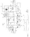
- FIG. 1 is shown in a sectional view from the side of a preferred embodiment of a cleaning device 110.
- the cleaning device is designed in this embodiment as a continuous dishwasher 112 and has a housing 114.
- This housing 114 may include, for example, a cleaning tunnel 116, which is designed, for example, completely or partially closed.
- the cleaning tunnel can be designed, for example, as a tunnel lined with cladding elements made of sheet metal.
- the cleaning tunnel 116 may be designed, for example, as a tunnel cladded with cladding elements made of sheet metal and / or plastic.
- the cleaning tunnel 116 may be configured to at least substantially prevent escape of steam and vapor from an interior region of the cleaning tunnel 116.
- the cleaning device further has in the illustrated embodiment, a transport device 118 to convey items 120 to be cleaned.
- this transport device 118 as in the illustrated embodiment, be designed as a basket transport device to convey items to be cleaned 120 in transport baskets 122 in a transport direction 130 through the cleaning tunnel 116.
- the cleaning device 110 and its housing 114 accordingly have an inlet 124 for placing the transport baskets 122 and / or the cleaning product 120 onto the transport device 118.
- the cleaning stock 120 enters the cleaning tunnel 116 through an inlet opening 123 and, in the illustrated embodiment, optionally passes through a plurality of cleaning zones 126 until the item to be cleaned 120 finally leaves the housing 114 at an outlet 127 and can be removed from the cleaning apparatus 110 ,
- the cleaning zones 126 in the interior of the cleaning device 110 may be separated from one another by separating curtains 128, for example.
- the cleaning zones 126 initially comprise two rinse zones 131, in which the cleaning product 120 is exposed to a cleaning fluid for the purpose of freeing the cleaning product 120 of adhering dirt residues.
- These rinse zones 131 are in turn divided into a Vorabhoffmzone 132, in which a rinsing coarse food residues or similar coarse impurities, and adjoining this Vorabhoffmzone 132 Hauptpülzone 142.
- the rinse zone 131 closes in the transport direction 130 again directly or indirectly For example, a rinse zone 149, which in turn is subdivided into a pump rinsing zone 150 and a downstream Frischiganklar Albanyzone 160.
- Each of these cleaning zones 126 preferably includes at least one cleaning system 134, which may include, for example, one or more nozzle systems.
- the pre-evacuation zone 132 includes one or more pre-evacuation zone spray nozzles 136 that may be powered from a pre-evacuation zone tank 138 by a pre-evacuation zone pump 140 in recirculation mode with cleaning fluid.
- the main scavenging zone 142 includes one or more main scavenging spray nozzles 144 which may be supplied with cleaning fluid from a main scavenging zone tank 146 in recirculation mode via a main scavenging pump 148.
- the rinse zone 149 is a departure from this design.
- This includes the pump rinse zone 150 having a pump rinse zone tank 152 from which a pump rinse zone spray nozzle system 156 may be fed via a pump rinse zone pump 158 with a rinse fluid.
- the rinse-off zone 159 downstream of the pump rinsing zone 150, also comprises a fresh-water rinsing zone 160.
- This comprises a fresh-water rinsing zone spray nozzle system 162, which can be supplied with fresh water via a fresh-water inlet 164.
- This fresh water also flows into the pump rinsing zone tank 152 after loading of the product to be cleaned 120 so that it can be used in the rinse pump zone 150 as rinse-aid fluid.
- the fresh water provided via the fresh water inlet 164 constitutes a first final rinse fluid.
- the fresh water already used once in the fresh water rinse zone 160 which is usually slightly contaminated, for example with cleaner residues, is used as the second rinse fluid in the pump rinse zone 150.
- the cleaning device 110 optionally a special supply of fresh water via a fresh water inlet 164, which is optionally performed by a heat recovery device 172 with a blower 174 done.
- the fresh water inlet 164 is further fed via a fresh water boiler 166 and / or a water heater before the fresh water is supplied to the fresh water rinse zone spray nozzle system.
- a fresh water boiler 166 and / or a water heater before the fresh water is supplied to the fresh water rinse zone spray nozzle system.
- another way of supplying fresh water is basically possible.
- the cleaning device 110 has a drying zone 168, which adjoins the cleaning zones 126 in the transport direction 130.
- This drying zone 168 optionally includes a blower 170.
- the cleaning device 110 in the illustrated embodiment comprises a controller 178, for example, a central machine control.
- a decentralized design of the control is also possible in principle. For example, program sequences of the cleaning device 110 can be controlled via the controller 178 and / or individual elements of the cleaning device 110 can be controlled.
- the cleaning device 110 as shown in FIG. 1 is exemplified, is just one of many possible embodiments, as the cleaning device 110 may be configured in principle.
- the cleaning device 110 should only comprise at least one cleaning zone 126, through which the items to be cleaned 120 are transported by means of a transport device 118 in order to be supplied with cleaning fluid in the at least one cleaning zone 126. Accordingly, numerous possible embodiments of the cleaning device 110 are possible and feasible within the scope of the present invention.
- the cleaning device 110 above the inlet opening 123 comprises at least one sensor 182, which in this case may be designed as a height-limiting sensor or height-limiting switch 180.
- the height limit switch 180 is configured in the illustrated embodiment, for example, as a trim part of the cleaning tunnel 116.
- it may comprise a foldable strip or plate extending over the entire clear width of the cleaning tunnel 116. If the item to be cleaned 120 is present, which protrudes upward beyond the lower edge of this bar, then the height limit switch 180 is pressed in, which can lead, for example, to stopping of the transport device 130.
- the sensor 182 may serve, for example, as a safety device in a first function, in order to avoid a faulty charging and / or another type of incorrect operation of the cleaning device 110. Accordingly, the sensor 182 may, for example, via an in FIG. 1 not shown interface with the controller 178 may be connected.
- the senor 182 may also be used by an operator of the cleaning device 110 to communicate control commands to the controller 178.
- the controller 178 and / or decentralized control parts may be arranged, for example, to be interpreted as control commands a multiple operation or other type of actuation, which differs from operation of the sensor 182 during normal operation of the cleaning device 110 by the cleaning 120.
- multiple actuations of the sensor 182 for example with a predetermined frequency, for example a minimum frequency or above a minimum frequency, can be interpreted as specific control commands.
- the controller 178 can detect, in addition to a simple switching pulse, such as a falling edge of a voltage signal, which can occur, for example, when actuated by the items to be cleaned 120, a sequence of switching signals, which arises, for example, when a user moves the foldable bar above the Inlet opening 124 repeatedly pressed at a high frequency.
- a sequence of switching signals can be detected and / or a falling and rising voltage edge can be detected and / or distinguished.
- reactions of the controller 178 and / or of the entire cleaning device 110 can generally be generated, for example the switching on of additional pumps 140, 148, 158 and / or the switching on of a blower 174, 170.
- Various designs are possible.
- FIGS. 2a and 2b is again the area of the inlet 124 of the cleaning device 110 shown in a perspective partial view. It shows FIG. 2a a resting state of the cleaning device 110. FIG. 2b shows, however, a state in which the sensor used as a universal switch 182 is pressed in the form of foldable bar above the inlet opening 123 inwards and thus actuated. It can be seen that the hinged bar spans substantially the entire width of the inlet opening 123. In this way, for example, operators of the cleaning device 110 from both sides of the inlet 124 ago this sensor 182, which serves as a universal switch, actuate and thus transmit, for example, control commands to the controller 178.
Landscapes
- Cleaning In General (AREA)
- Washing And Drying Of Tableware (AREA)
- Cleaning By Liquid Or Steam (AREA)
Claims (11)
- Dispositif de nettoyage (110) pour le nettoyage de produits à nettoyer (120), comprenant au moins une zone de nettoyage (126) pour appliquer du fluide nettoyant sur le produit à nettoyer (120), comprenant par ailleurs au moins un dispositif de transport (118) pour transporter le produit à nettoyer (120) à travers la zone de nettoyage (126), le dispositif de nettoyage (110) comportant par ailleurs un capteur (182) pour la détection du produit à nettoyer (120), le capteur (182) étant accessible par l'extérieur par un utilisateur du dispositif de nettoyage (110) et le dispositif de nettoyage (110) étant aménagé pour permettre à un utilisateur, par actionnement du capteur (182) une transmission d'instructions de commande à un système de commande (178) du dispositif de nettoyage (110), caractérisé en ce que le capteur (182) peut être actionné par l'utilisateur selon au moins un type d'actionnement qui se distingue d'un actionnement du capteur (182) par le produit à nettoyer (120) et le système de commande (178) étant aménagé pour interpréter ledit actionnement comme une instruction de commande.
- Dispositif de nettoyage (110) selon la revendication précédente, le type d'actionnement comprenant un actionnement répété du capteur (182), notamment un actionnement répété à une fréquence minimale.
- Dispositif de nettoyage (110) selon la revendication précédente, au moins deux types d'actionnement étant prévus qui se distinguent en un nombre d'actionnements du capteur (182), le système de commande (178) étant aménagé pour interpréter les au moins deux types d'actionnement comme des instructions de commande différentes.
- Dispositif de nettoyage (110) selon l'une quelconque des revendications précédentes, l'instruction de commande comprenant l'une ou plusieurs des instructions de commande suivantes : une coupure du dispositif de transport (118) ; un démarrage du dispositif de transport (118) ; une modification d'une vitesse de transport du dispositif de transport (118) ; un amorçage d'une pompe (140, 148, 158), pour le transport de l'au moins un fluide nettoyant, notamment un lancement ou une coupure de la pompe (140, 148, 158) ; un amorçage d'au moins une soufflante (170, 174), notamment un lancement ou une coupure de la soufflante (170, 174) ; un renversement d'une direction de transport (130).
- Dispositif de nettoyage (110) selon l'une quelconque des revendications précédentes, le dispositif de nettoyage (110) comportant au moins un tunnel de nettoyage (116) et au moins une entrée (124), l'au moins une zone de nettoyage (126) étant logée dans le tunnel de nettoyage (116), le produit à nettoyer (120) pénétrant dans le tunnel de nettoyage (116) à l'entrée (124), l'au moins un capteur (182) étant placé à l'entrée (124).
- Dispositif de nettoyage (110) selon l'une quelconque des revendications précédentes, le capteur (182) étant actionnable à l'entrée (124) par un utilisateur, à partir des deux côtés du dispositif de transport (118).
- Dispositif de nettoyage (110) selon l'une quelconque des deux revendications précédentes, le capteur (182) recouvrant au moins en partie au moins une ouverture d'entrée (123) de l'entrée (124).
- Dispositif de nettoyage (110) selon l'une quelconque des revendications précédentes, le capteur (182) comprenant une pièce d'habillage mobile du dispositif de nettoyage (110), notamment une pièce d'habillage au-dessus d'une ouverture d'entrée (123) du dispositif de nettoyage (110), notamment une baguette rabattable, un panneau rabattable ou un étrier rabattable.
- Dispositif de nettoyage (110) selon l'une quelconque des revendications précédentes, le capteur (182) comprenant au moins un capteur de hauteur (180) pour détecter une sur-hauteur du produit à nettoyer (120) et/ou au moins un capteur de largeur pour détecter une sur-largeur du produit à nettoyer (120).
- Dispositif de nettoyage (110) selon l'une quelconque des revendications précédentes, le capteur (182) comprenant au moins l'un des capteurs (182) suivants : un capteur optique, notamment une barrière lumineuse, un capteur (182) mécanique, notamment un capteur à câble, un interrupteur, notamment un interrupteur à poussoir et/ou un interrupteur à bascule, un étrier pivotant, une barre de commutation escamotable.
- Procédé destiné à commander un dispositif de nettoyage (110), notamment un dispositif de nettoyage (110) selon l'une quelconque des revendications précédentes, au moins un capteur (182) étant utilisé pour détecter le produit à nettoyer (120), le capteur (182) étant accessible par l'extérieur par un utilisateur du dispositif de nettoyage (110) et le capteur (182) étant utilisé en supplément pour la transmission d'instructions de commande d'un utilisateur à un système de commande (178) du dispositif de nettoyage (110), caractérisé en ce que le capteur (182) est actionné par l'utilisateur selon au moins un type d'actionnement qui se distingue d'un actionnement du capteur (182) par le produit à nettoyer (120) et le système de commande (178) étant aménagé pour interpréter ledit actionnement comme une instruction de commande.
Applications Claiming Priority (1)
| Application Number | Priority Date | Filing Date | Title |
|---|---|---|---|
| DE102009059784.0A DE102009059784B4 (de) | 2009-12-18 | 2009-12-18 | Reinigungsvorrichtung mit Betätigungselement |
Publications (4)
| Publication Number | Publication Date |
|---|---|
| EP2335546A2 EP2335546A2 (fr) | 2011-06-22 |
| EP2335546A3 EP2335546A3 (fr) | 2014-12-31 |
| EP2335546B1 true EP2335546B1 (fr) | 2016-03-02 |
| EP2335546B2 EP2335546B2 (fr) | 2019-03-20 |
Family
ID=43881170
Family Applications (1)
| Application Number | Title | Priority Date | Filing Date |
|---|---|---|---|
| EP10014760.2A Not-in-force EP2335546B2 (fr) | 2009-12-18 | 2010-11-18 | Dispositif de nettoyage doté d'un élément d'actionnement |
Country Status (2)
| Country | Link |
|---|---|
| EP (1) | EP2335546B2 (fr) |
| DE (1) | DE102009059784B4 (fr) |
Families Citing this family (2)
| Publication number | Priority date | Publication date | Assignee | Title |
|---|---|---|---|---|
| DE102015214300B4 (de) | 2015-07-28 | 2026-02-05 | Illinois Tool Works Inc. | Transportspülmaschine sowie Verfahren zum Betreiben einer Transportspülmaschine |
| CN115463848B (zh) * | 2022-09-05 | 2024-07-30 | 东莞市华美食品有限公司 | 一种食品残渣吹扫控制方法及设备 |
Citations (10)
| Publication number | Priority date | Publication date | Assignee | Title |
|---|---|---|---|---|
| US1846083A (en) | 1931-01-29 | 1932-02-23 | Eugene W Bowker | Automatic conveyer control |
| US4561904A (en) | 1984-09-21 | 1985-12-31 | Hobart Corporation | Control system and method of controlling a dishwashing machine |
| DE19608034C1 (de) | 1996-03-02 | 1997-07-10 | Stierlen Maquet Ag | Reinigungsmaschine, insbesondere für Geschirr mit einer Einlaufsicherung für zu großes Spülgut |
| DE19829650A1 (de) | 1998-07-02 | 2000-01-05 | Premark Feg Llc | Durchlaufgeschirrspülvorrichtung für Geschirrkörbe und Verfahren zum Betrieb davon |
| WO2000053076A1 (fr) | 1999-03-05 | 2000-09-14 | Hackman Metos Oy | Lavage automatique d'articles |
| DE10053030A1 (de) | 2000-10-26 | 2002-05-08 | Miele & Cie | Verfahren zur Erkennung der Beladung einer programmgesteuerten Geschirrspülmaschine zur Durchführung des Verfahrens |
| DE10058410A1 (de) | 2000-11-24 | 2002-09-19 | Bsh Bosch Siemens Hausgeraete | Anzeigevorrichtung |
| DE69525337T2 (de) | 1994-05-02 | 2003-03-13 | Fuuga-Controls Oy, Tampere | Methode zum waschen von gegenständen in einer waschstrasse und waschanlage |
| DE102005014353A1 (de) | 2005-03-24 | 2006-09-28 | Premark Feg L.L.C., Wilmington | Transportspülmaschine und Verfahren hierfür |
| DE102008014318A1 (de) | 2008-03-14 | 2009-09-17 | Premark Feg L.L.C., Wilmington | Transportspülmaschine und Verfahren zum Betreiben einer Transportspülmaschine |
-
2009
- 2009-12-18 DE DE102009059784.0A patent/DE102009059784B4/de not_active Revoked
-
2010
- 2010-11-18 EP EP10014760.2A patent/EP2335546B2/fr not_active Not-in-force
Patent Citations (10)
| Publication number | Priority date | Publication date | Assignee | Title |
|---|---|---|---|---|
| US1846083A (en) | 1931-01-29 | 1932-02-23 | Eugene W Bowker | Automatic conveyer control |
| US4561904A (en) | 1984-09-21 | 1985-12-31 | Hobart Corporation | Control system and method of controlling a dishwashing machine |
| DE69525337T2 (de) | 1994-05-02 | 2003-03-13 | Fuuga-Controls Oy, Tampere | Methode zum waschen von gegenständen in einer waschstrasse und waschanlage |
| DE19608034C1 (de) | 1996-03-02 | 1997-07-10 | Stierlen Maquet Ag | Reinigungsmaschine, insbesondere für Geschirr mit einer Einlaufsicherung für zu großes Spülgut |
| DE19829650A1 (de) | 1998-07-02 | 2000-01-05 | Premark Feg Llc | Durchlaufgeschirrspülvorrichtung für Geschirrkörbe und Verfahren zum Betrieb davon |
| WO2000053076A1 (fr) | 1999-03-05 | 2000-09-14 | Hackman Metos Oy | Lavage automatique d'articles |
| DE10053030A1 (de) | 2000-10-26 | 2002-05-08 | Miele & Cie | Verfahren zur Erkennung der Beladung einer programmgesteuerten Geschirrspülmaschine zur Durchführung des Verfahrens |
| DE10058410A1 (de) | 2000-11-24 | 2002-09-19 | Bsh Bosch Siemens Hausgeraete | Anzeigevorrichtung |
| DE102005014353A1 (de) | 2005-03-24 | 2006-09-28 | Premark Feg L.L.C., Wilmington | Transportspülmaschine und Verfahren hierfür |
| DE102008014318A1 (de) | 2008-03-14 | 2009-09-17 | Premark Feg L.L.C., Wilmington | Transportspülmaschine und Verfahren zum Betreiben einer Transportspülmaschine |
Also Published As
| Publication number | Publication date |
|---|---|
| EP2335546A3 (fr) | 2014-12-31 |
| EP2335546B2 (fr) | 2019-03-20 |
| EP2335546A2 (fr) | 2011-06-22 |
| DE102009059784A1 (de) | 2011-06-22 |
| DE102009059784B4 (de) | 2016-05-12 |
Similar Documents
| Publication | Publication Date | Title |
|---|---|---|
| DE102008037344B4 (de) | Transportspülmaschine und Verfahren zum Betreiben einer Transportspülmaschine | |
| EP2866635B1 (fr) | Dispositif de nettoyage comprenant un système de buse de rinçage final à déclenchement individuel | |
| EP3107438A1 (fr) | Dispositif de nettoyage adapté aux besoins | |
| DE102015214300B4 (de) | Transportspülmaschine sowie Verfahren zum Betreiben einer Transportspülmaschine | |
| WO2019015968A1 (fr) | Lave-vaisselle doté d'au moins une porte pouvant être mise en place automatiquement lors du fonctionnement | |
| DE102008014921A1 (de) | Transportspülmaschine sowie Verfahren zum Betreiben einer Transportspülmaschine | |
| DE102005014353A1 (de) | Transportspülmaschine und Verfahren hierfür | |
| DE102013226080A1 (de) | Reinigungsvorrichtung und Verfahren zum Reinigen von Reinigungsgut | |
| DE102017121978A1 (de) | Spülmaschine | |
| EP3840626B1 (fr) | Système de nettoyage et procédé de nettoyage de produit à nettoyer | |
| EP3860420A1 (fr) | Système de nettoyage et procédé de nettoyage d'articles à nettoyer | |
| DE102009032964A1 (de) | Verfahren zum Betrieb einer Mehrtankgeschirrspülmaschine | |
| EP2335546B1 (fr) | Dispositif de nettoyage doté d'un élément d'actionnement | |
| EP3860419B1 (fr) | Dispositif de nettoyage et procédé de nettoyage d'articles à nettoyer | |
| WO2017202574A1 (fr) | Lave-vaisselle domestique | |
| EP3906834A1 (fr) | Système de chargement de différentes voies de transport d'au moins une bobinoir et agencement de bobinoir doté d'un tel système | |
| DE102012100671A1 (de) | Spülmaschine, insbesondere Gewerbespülmaschine | |
| DE102014209765A1 (de) | Reinigungsvorrichtung mit verbesserter Trocknung | |
| EP3870015B1 (fr) | Système de nettoyage et procédé de nettoyage d'article à nettoyer | |
| DE102020114364A1 (de) | System zum beladen mindestens einer transportspülmaschine mit spülgutteilen, anordnung aus mindestens einer transportspülmaschine und einem beladesystem sowie verfahren zum beladen mindestens einer transportspülmaschine mit spülgutteilen | |
| DE102009045595A1 (de) | Haushaltsgerät, insbesondere Haushalts-Geschirrspülmaschine | |
| EP4536054A1 (fr) | Module de retrait et procédé de retrait d'assiettes | |
| DE102023205649A1 (de) | Reinigungsvorrichtung und Verfahren zur Reinigung von Reinigungsgut | |
| DE102015122782B4 (de) | Verbesserte Waschvorrichtung für eine Tunnelgeschirrspülmaschine und zugeordnete Geschirrspülmaschine | |
| DE102012019732A1 (de) | Durchlaufgeschirrspülmaschine |
Legal Events
| Date | Code | Title | Description |
|---|---|---|---|
| PUAI | Public reference made under article 153(3) epc to a published international application that has entered the european phase |
Free format text: ORIGINAL CODE: 0009012 |
|
| AK | Designated contracting states |
Kind code of ref document: A2 Designated state(s): AL AT BE BG CH CY CZ DE DK EE ES FI FR GB GR HR HU IE IS IT LI LT LU LV MC MK MT NL NO PL PT RO RS SE SI SK SM TR |
|
| AX | Request for extension of the european patent |
Extension state: BA ME |
|
| PUAL | Search report despatched |
Free format text: ORIGINAL CODE: 0009013 |
|
| AK | Designated contracting states |
Kind code of ref document: A3 Designated state(s): AL AT BE BG CH CY CZ DE DK EE ES FI FR GB GR HR HU IE IS IT LI LT LU LV MC MK MT NL NO PL PT RO RS SE SI SK SM TR |
|
| AX | Request for extension of the european patent |
Extension state: BA ME |
|
| RIC1 | Information provided on ipc code assigned before grant |
Ipc: A47L 15/42 20060101ALI20141125BHEP Ipc: A47L 15/24 20060101AFI20141125BHEP |
|
| 17P | Request for examination filed |
Effective date: 20150220 |
|
| RBV | Designated contracting states (corrected) |
Designated state(s): AL AT BE BG CH CY CZ DE DK EE ES FI FR GB GR HR HU IE IS IT LI LT LU LV MC MK MT NL NO PL PT RO RS SE SI SK SM TR |
|
| GRAP | Despatch of communication of intention to grant a patent |
Free format text: ORIGINAL CODE: EPIDOSNIGR1 |
|
| RIC1 | Information provided on ipc code assigned before grant |
Ipc: A47L 15/24 20060101AFI20150806BHEP Ipc: A47L 15/42 20060101ALI20150806BHEP |
|
| INTG | Intention to grant announced |
Effective date: 20150825 |
|
| GRAS | Grant fee paid |
Free format text: ORIGINAL CODE: EPIDOSNIGR3 |
|
| GRAA | (expected) grant |
Free format text: ORIGINAL CODE: 0009210 |
|
| AK | Designated contracting states |
Kind code of ref document: B1 Designated state(s): AL AT BE BG CH CY CZ DE DK EE ES FI FR GB GR HR HU IE IS IT LI LT LU LV MC MK MT NL NO PL PT RO RS SE SI SK SM TR |
|
| REG | Reference to a national code |
Ref country code: GB Ref legal event code: FG4D Free format text: NOT ENGLISH |
|
| REG | Reference to a national code |
Ref country code: AT Ref legal event code: REF Ref document number: 777388 Country of ref document: AT Kind code of ref document: T Effective date: 20160315 Ref country code: CH Ref legal event code: EP |
|
| REG | Reference to a national code |
Ref country code: IE Ref legal event code: FG4D Free format text: LANGUAGE OF EP DOCUMENT: GERMAN |
|
| REG | Reference to a national code |
Ref country code: DE Ref legal event code: R096 Ref document number: 502010011103 Country of ref document: DE |
|
| REG | Reference to a national code |
Ref country code: NL Ref legal event code: MP Effective date: 20160302 |
|
| REG | Reference to a national code |
Ref country code: LT Ref legal event code: MG4D |
|
| PG25 | Lapsed in a contracting state [announced via postgrant information from national office to epo] |
Ref country code: HR Free format text: LAPSE BECAUSE OF FAILURE TO SUBMIT A TRANSLATION OF THE DESCRIPTION OR TO PAY THE FEE WITHIN THE PRESCRIBED TIME-LIMIT Effective date: 20160302 Ref country code: FI Free format text: LAPSE BECAUSE OF FAILURE TO SUBMIT A TRANSLATION OF THE DESCRIPTION OR TO PAY THE FEE WITHIN THE PRESCRIBED TIME-LIMIT Effective date: 20160302 Ref country code: ES Free format text: LAPSE BECAUSE OF FAILURE TO SUBMIT A TRANSLATION OF THE DESCRIPTION OR TO PAY THE FEE WITHIN THE PRESCRIBED TIME-LIMIT Effective date: 20160302 Ref country code: GR Free format text: LAPSE BECAUSE OF FAILURE TO SUBMIT A TRANSLATION OF THE DESCRIPTION OR TO PAY THE FEE WITHIN THE PRESCRIBED TIME-LIMIT Effective date: 20160603 Ref country code: NO Free format text: LAPSE BECAUSE OF FAILURE TO SUBMIT A TRANSLATION OF THE DESCRIPTION OR TO PAY THE FEE WITHIN THE PRESCRIBED TIME-LIMIT Effective date: 20160602 |
|
| PG25 | Lapsed in a contracting state [announced via postgrant information from national office to epo] |
Ref country code: LV Free format text: LAPSE BECAUSE OF FAILURE TO SUBMIT A TRANSLATION OF THE DESCRIPTION OR TO PAY THE FEE WITHIN THE PRESCRIBED TIME-LIMIT Effective date: 20160302 Ref country code: RS Free format text: LAPSE BECAUSE OF FAILURE TO SUBMIT A TRANSLATION OF THE DESCRIPTION OR TO PAY THE FEE WITHIN THE PRESCRIBED TIME-LIMIT Effective date: 20160302 Ref country code: SE Free format text: LAPSE BECAUSE OF FAILURE TO SUBMIT A TRANSLATION OF THE DESCRIPTION OR TO PAY THE FEE WITHIN THE PRESCRIBED TIME-LIMIT Effective date: 20160302 Ref country code: NL Free format text: LAPSE BECAUSE OF FAILURE TO SUBMIT A TRANSLATION OF THE DESCRIPTION OR TO PAY THE FEE WITHIN THE PRESCRIBED TIME-LIMIT Effective date: 20160302 Ref country code: PL Free format text: LAPSE BECAUSE OF FAILURE TO SUBMIT A TRANSLATION OF THE DESCRIPTION OR TO PAY THE FEE WITHIN THE PRESCRIBED TIME-LIMIT Effective date: 20160302 Ref country code: LT Free format text: LAPSE BECAUSE OF FAILURE TO SUBMIT A TRANSLATION OF THE DESCRIPTION OR TO PAY THE FEE WITHIN THE PRESCRIBED TIME-LIMIT Effective date: 20160302 |
|
| PG25 | Lapsed in a contracting state [announced via postgrant information from national office to epo] |
Ref country code: IS Free format text: LAPSE BECAUSE OF FAILURE TO SUBMIT A TRANSLATION OF THE DESCRIPTION OR TO PAY THE FEE WITHIN THE PRESCRIBED TIME-LIMIT Effective date: 20160702 Ref country code: EE Free format text: LAPSE BECAUSE OF FAILURE TO SUBMIT A TRANSLATION OF THE DESCRIPTION OR TO PAY THE FEE WITHIN THE PRESCRIBED TIME-LIMIT Effective date: 20160302 |
|
| REG | Reference to a national code |
Ref country code: FR Ref legal event code: PLFP Year of fee payment: 7 |
|
| PG25 | Lapsed in a contracting state [announced via postgrant information from national office to epo] |
Ref country code: CZ Free format text: LAPSE BECAUSE OF FAILURE TO SUBMIT A TRANSLATION OF THE DESCRIPTION OR TO PAY THE FEE WITHIN THE PRESCRIBED TIME-LIMIT Effective date: 20160302 Ref country code: SK Free format text: LAPSE BECAUSE OF FAILURE TO SUBMIT A TRANSLATION OF THE DESCRIPTION OR TO PAY THE FEE WITHIN THE PRESCRIBED TIME-LIMIT Effective date: 20160302 Ref country code: PT Free format text: LAPSE BECAUSE OF FAILURE TO SUBMIT A TRANSLATION OF THE DESCRIPTION OR TO PAY THE FEE WITHIN THE PRESCRIBED TIME-LIMIT Effective date: 20160704 Ref country code: RO Free format text: LAPSE BECAUSE OF FAILURE TO SUBMIT A TRANSLATION OF THE DESCRIPTION OR TO PAY THE FEE WITHIN THE PRESCRIBED TIME-LIMIT Effective date: 20160302 Ref country code: SM Free format text: LAPSE BECAUSE OF FAILURE TO SUBMIT A TRANSLATION OF THE DESCRIPTION OR TO PAY THE FEE WITHIN THE PRESCRIBED TIME-LIMIT Effective date: 20160302 |
|
| REG | Reference to a national code |
Ref country code: DE Ref legal event code: R026 Ref document number: 502010011103 Country of ref document: DE |
|
| PLBI | Opposition filed |
Free format text: ORIGINAL CODE: 0009260 |
|
| PLAX | Notice of opposition and request to file observation + time limit sent |
Free format text: ORIGINAL CODE: EPIDOSNOBS2 |
|
| 26 | Opposition filed |
Opponent name: HOBART GMBH Effective date: 20161202 |
|
| PG25 | Lapsed in a contracting state [announced via postgrant information from national office to epo] |
Ref country code: DK Free format text: LAPSE BECAUSE OF FAILURE TO SUBMIT A TRANSLATION OF THE DESCRIPTION OR TO PAY THE FEE WITHIN THE PRESCRIBED TIME-LIMIT Effective date: 20160302 |
|
| PG25 | Lapsed in a contracting state [announced via postgrant information from national office to epo] |
Ref country code: BE Free format text: LAPSE BECAUSE OF NON-PAYMENT OF DUE FEES Effective date: 20161130 Ref country code: SI Free format text: LAPSE BECAUSE OF FAILURE TO SUBMIT A TRANSLATION OF THE DESCRIPTION OR TO PAY THE FEE WITHIN THE PRESCRIBED TIME-LIMIT Effective date: 20160302 Ref country code: BG Free format text: LAPSE BECAUSE OF FAILURE TO SUBMIT A TRANSLATION OF THE DESCRIPTION OR TO PAY THE FEE WITHIN THE PRESCRIBED TIME-LIMIT Effective date: 20160602 |
|
| PLBB | Reply of patent proprietor to notice(s) of opposition received |
Free format text: ORIGINAL CODE: EPIDOSNOBS3 |
|
| REG | Reference to a national code |
Ref country code: CH Ref legal event code: PL |
|
| GBPC | Gb: european patent ceased through non-payment of renewal fee |
Effective date: 20161118 |
|
| PG25 | Lapsed in a contracting state [announced via postgrant information from national office to epo] |
Ref country code: CH Free format text: LAPSE BECAUSE OF NON-PAYMENT OF DUE FEES Effective date: 20161130 Ref country code: LI Free format text: LAPSE BECAUSE OF NON-PAYMENT OF DUE FEES Effective date: 20161130 |
|
| REG | Reference to a national code |
Ref country code: IE Ref legal event code: MM4A |
|
| PG25 | Lapsed in a contracting state [announced via postgrant information from national office to epo] |
Ref country code: LU Free format text: LAPSE BECAUSE OF NON-PAYMENT OF DUE FEES Effective date: 20161130 |
|
| REG | Reference to a national code |
Ref country code: FR Ref legal event code: PLFP Year of fee payment: 8 |
|
| PG25 | Lapsed in a contracting state [announced via postgrant information from national office to epo] |
Ref country code: GB Free format text: LAPSE BECAUSE OF NON-PAYMENT OF DUE FEES Effective date: 20161118 Ref country code: IE Free format text: LAPSE BECAUSE OF NON-PAYMENT OF DUE FEES Effective date: 20161118 |
|
| REG | Reference to a national code |
Ref country code: AT Ref legal event code: MM01 Ref document number: 777388 Country of ref document: AT Kind code of ref document: T Effective date: 20161118 |
|
| PG25 | Lapsed in a contracting state [announced via postgrant information from national office to epo] |
Ref country code: AT Free format text: LAPSE BECAUSE OF NON-PAYMENT OF DUE FEES Effective date: 20161118 |
|
| REG | Reference to a national code |
Ref country code: BE Ref legal event code: MM Effective date: 20161130 |
|
| PG25 | Lapsed in a contracting state [announced via postgrant information from national office to epo] |
Ref country code: CY Free format text: LAPSE BECAUSE OF FAILURE TO SUBMIT A TRANSLATION OF THE DESCRIPTION OR TO PAY THE FEE WITHIN THE PRESCRIBED TIME-LIMIT Effective date: 20160302 Ref country code: HU Free format text: LAPSE BECAUSE OF FAILURE TO SUBMIT A TRANSLATION OF THE DESCRIPTION OR TO PAY THE FEE WITHIN THE PRESCRIBED TIME-LIMIT; INVALID AB INITIO Effective date: 20101118 |
|
| PG25 | Lapsed in a contracting state [announced via postgrant information from national office to epo] |
Ref country code: MC Free format text: LAPSE BECAUSE OF FAILURE TO SUBMIT A TRANSLATION OF THE DESCRIPTION OR TO PAY THE FEE WITHIN THE PRESCRIBED TIME-LIMIT Effective date: 20160302 Ref country code: TR Free format text: LAPSE BECAUSE OF FAILURE TO SUBMIT A TRANSLATION OF THE DESCRIPTION OR TO PAY THE FEE WITHIN THE PRESCRIBED TIME-LIMIT Effective date: 20160302 Ref country code: MK Free format text: LAPSE BECAUSE OF FAILURE TO SUBMIT A TRANSLATION OF THE DESCRIPTION OR TO PAY THE FEE WITHIN THE PRESCRIBED TIME-LIMIT Effective date: 20160302 |
|
| RIC2 | Information provided on ipc code assigned after grant |
Ipc: A47L 15/24 20060101ALI20180710BHEP Ipc: A47L 15/00 20060101AFI20180710BHEP |
|
| PG25 | Lapsed in a contracting state [announced via postgrant information from national office to epo] |
Ref country code: MT Free format text: LAPSE BECAUSE OF FAILURE TO SUBMIT A TRANSLATION OF THE DESCRIPTION OR TO PAY THE FEE WITHIN THE PRESCRIBED TIME-LIMIT Effective date: 20160302 |
|
| PG25 | Lapsed in a contracting state [announced via postgrant information from national office to epo] |
Ref country code: AL Free format text: LAPSE BECAUSE OF FAILURE TO SUBMIT A TRANSLATION OF THE DESCRIPTION OR TO PAY THE FEE WITHIN THE PRESCRIBED TIME-LIMIT Effective date: 20160302 |
|
| PUAH | Patent maintained in amended form |
Free format text: ORIGINAL CODE: 0009272 |
|
| STAA | Information on the status of an ep patent application or granted ep patent |
Free format text: STATUS: PATENT MAINTAINED AS AMENDED |
|
| 27A | Patent maintained in amended form |
Effective date: 20190320 |
|
| AK | Designated contracting states |
Kind code of ref document: B2 Designated state(s): AL AT BE BG CH CY CZ DE DK EE ES FI FR GB GR HR HU IE IS IT LI LT LU LV MC MK MT NL NO PL PT RO RS SE SI SK SM TR |
|
| REG | Reference to a national code |
Ref country code: DE Ref legal event code: R102 Ref document number: 502010011103 Country of ref document: DE |
|
| PGFP | Annual fee paid to national office [announced via postgrant information from national office to epo] |
Ref country code: IT Payment date: 20221130 Year of fee payment: 13 Ref country code: FR Payment date: 20221125 Year of fee payment: 13 Ref country code: DE Payment date: 20221128 Year of fee payment: 13 |
|
| P01 | Opt-out of the competence of the unified patent court (upc) registered |
Effective date: 20230525 |
|
| REG | Reference to a national code |
Ref country code: DE Ref legal event code: R119 Ref document number: 502010011103 Country of ref document: DE |
|
| PG25 | Lapsed in a contracting state [announced via postgrant information from national office to epo] |
Ref country code: DE Free format text: LAPSE BECAUSE OF NON-PAYMENT OF DUE FEES Effective date: 20240601 |
|
| PG25 | Lapsed in a contracting state [announced via postgrant information from national office to epo] |
Ref country code: FR Free format text: LAPSE BECAUSE OF NON-PAYMENT OF DUE FEES Effective date: 20231130 |
|
| PG25 | Lapsed in a contracting state [announced via postgrant information from national office to epo] |
Ref country code: FR Free format text: LAPSE BECAUSE OF NON-PAYMENT OF DUE FEES Effective date: 20231130 Ref country code: DE Free format text: LAPSE BECAUSE OF NON-PAYMENT OF DUE FEES Effective date: 20240601 |
|
| PG25 | Lapsed in a contracting state [announced via postgrant information from national office to epo] |
Ref country code: IT Free format text: LAPSE BECAUSE OF NON-PAYMENT OF DUE FEES Effective date: 20231118 |
|
| PG25 | Lapsed in a contracting state [announced via postgrant information from national office to epo] |
Ref country code: IT Free format text: LAPSE BECAUSE OF NON-PAYMENT OF DUE FEES Effective date: 20231118 |