EP2336441A2 - Rail d'ancrage pour couler dans le béton - Google Patents
Rail d'ancrage pour couler dans le béton Download PDFInfo
- Publication number
- EP2336441A2 EP2336441A2 EP10015807A EP10015807A EP2336441A2 EP 2336441 A2 EP2336441 A2 EP 2336441A2 EP 10015807 A EP10015807 A EP 10015807A EP 10015807 A EP10015807 A EP 10015807A EP 2336441 A2 EP2336441 A2 EP 2336441A2
- Authority
- EP
- European Patent Office
- Prior art keywords
- anchor rail
- profile
- bending
- anchor
- bending tab
- Prior art date
- Legal status (The legal status is an assumption and is not a legal conclusion. Google has not performed a legal analysis and makes no representation as to the accuracy of the status listed.)
- Withdrawn
Links
- 239000004567 concrete Substances 0.000 title claims description 16
- 238000005452 bending Methods 0.000 claims abstract description 56
- 239000000463 material Substances 0.000 claims abstract description 26
- 238000004873 anchoring Methods 0.000 claims description 6
- 238000005520 cutting process Methods 0.000 description 8
- 238000004519 manufacturing process Methods 0.000 description 4
- 239000002184 metal Substances 0.000 description 4
- 238000005253 cladding Methods 0.000 description 3
- 239000002131 composite material Substances 0.000 description 3
- 238000009434 installation Methods 0.000 description 3
- 239000011178 precast concrete Substances 0.000 description 3
- 238000003466 welding Methods 0.000 description 3
- 238000005553 drilling Methods 0.000 description 2
- 230000002349 favourable effect Effects 0.000 description 2
- 238000009423 ventilation Methods 0.000 description 2
- 238000004378 air conditioning Methods 0.000 description 1
- 230000015572 biosynthetic process Effects 0.000 description 1
- 239000006260 foam Substances 0.000 description 1
- 238000009415 formwork Methods 0.000 description 1
- 238000009413 insulation Methods 0.000 description 1
- 238000003698 laser cutting Methods 0.000 description 1
- 239000007788 liquid Substances 0.000 description 1
- 230000035515 penetration Effects 0.000 description 1
- 230000003014 reinforcing effect Effects 0.000 description 1
- 238000010079 rubber tapping Methods 0.000 description 1
Images




Classifications
-
- E—FIXED CONSTRUCTIONS
- E04—BUILDING
- E04B—GENERAL BUILDING CONSTRUCTIONS; WALLS, e.g. PARTITIONS; ROOFS; FLOORS; CEILINGS; INSULATION OR OTHER PROTECTION OF BUILDINGS
- E04B1/00—Constructions in general; Structures which are not restricted either to walls, e.g. partitions, or floors or ceilings or roofs
- E04B1/38—Connections for building structures in general
- E04B1/41—Connecting devices specially adapted for embedding in concrete or masonry
-
- E—FIXED CONSTRUCTIONS
- E04—BUILDING
- E04B—GENERAL BUILDING CONSTRUCTIONS; WALLS, e.g. PARTITIONS; ROOFS; FLOORS; CEILINGS; INSULATION OR OTHER PROTECTION OF BUILDINGS
- E04B1/00—Constructions in general; Structures which are not restricted either to walls, e.g. partitions, or floors or ceilings or roofs
- E04B1/38—Connections for building structures in general
- E04B1/41—Connecting devices specially adapted for embedding in concrete or masonry
- E04B1/4107—Longitudinal elements having an open profile, with the opening parallel to the concrete or masonry surface, i.e. anchoring rails
Definitions
- the invention relates to an anchor rail for setting in concrete in concrete according to the preamble of claim 1.
- Halfen anchor rails which consist of a semi-open profile, in particular a U-profile, which is optionally filled in its interior with a Dämmst Shape or full foam filling.
- Such anchor rails are inserted into the formwork for the production of a precast concrete slab and poured with, which then a special bond between the anchor rail in concrete precast slab is achieved.
- the known anchor rail should provide an increased capacity at the specific areas, it is known that are welded or screwed to the base leg of the anchor rail head bolts, which extend into the concrete and anchored there. This is intended to improve the anchoring of the anchor rail in the concrete.
- I-profiles are double-T-shaped profile strips which are welded onto the base leg of the anchor rail and thus also improve their bond in the concrete material of the precast slab.
- the invention is therefore the object of developing an anchor rail of the type mentioned so that a much cheaper production is guaranteed.
- the invention is characterized by the technical teaching of claim 1.
- An essential feature of the invention is that at least one of the legs of the anchor rail (be it the base leg or one or more of the side legs) a bending tab is divided in such a way that with the aid of a cutting tool a three-sided circumferential cutting edge is generated in the leg of the anchor rail, whereby a one-sided connected to the leg sheet metal strip is formed, which is bent from the plane of the leg upwards.
- the bending tab is now generated from the material of the anchor rail itself, which is cut at least on three sides with cutting lines, so that thus a bending tab is formed, which is still connected via a bending edge with the material of the anchor rail.
- the anchor rail is formed as a U-profile, this is not to be understood as limiting. Only for the sake of simpler description, it is assumed in the following description of the formation of the anchor rail as a U-profile.
- the anchor rail can also be formed from other profile shapes, such. B. semi-circular profiles, elliptical profiles, polygonal profiles and the like. It is only essential that the anchor rail is designed as a semi-open profile in order to achieve a relation to the respective bending tab arranged continuous open groove into which corresponding fasteners can be inserted, plugged or secured in any other way.
- the invention is not limited thereto. It can be cut out of the side legs of the half-open profile even more bending tabs or it may be provided on the side legs a combination of bending tabs on the base leg and bending tabs.
- this rotation can be done either in the region of the bending edge next to the base leg of the anchor rail, or the bending tab can also be rotated at its upper free end by 90 °.
- the invention thus leaves it completely open, whether a lower or an upper twist of the bending tab is present or whether both twists are given.
- the bending tab can thus be twisted out of the material of the base leg once or several times by 90 ° in the raised position.
- the bent out of the material of the base leg bending tab still now additionally receives edge cuts in order to achieve an even better bond in the concrete material.
- the bending tab is pierced in order to achieve through drilling openings also a penetration of concrete material in these open positions.
- an approximately vertically extending slot protrudes partially in the direction of the longitudinal axis of the bending tab in the material of the bending tab and the slot thus defines two expansion halves of the bending tab, with a separate tool apart can be spread so as to be spread over the existing width of the bending tab out.
- any fastening elements can be inserted into the U-profile of the anchor rail or fastened in another way to serve as a holder for objects to be fastened thereto.
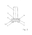
- an anchor rail 1 which preferably consists of a U-profile 2. It has already been pointed out in the general description section that the present embodiment description relates to a U-profile only for the sake of simpler description, but that also other profile shapes can be used.
- Such a U-profile consists of a base leg 3, on the material integral, the two side legs 4, 5 are formed, which may possibly even in frontal side legs 4 'and 5' can pass.
- the task of the insulating strip 11 is to ensure that the liquid concrete material does not flow into the interior of the anchor rail 1 when the anchor rail 1 is cast in the prefabricated panels 24, 26 shown below.
- the insulating strip may remain at the location of its installation, or it may also be removed after setting in the prefabricated panels 24, 26.
- FIG. 1 be made with a suitable cutting tool, in particular a laser cutter three contiguous cutting lines in the material of the base leg 3, which merge into each other at an angle of 90 °, so that thus a three-sided limited bending tab 6 is cut out of the material of the base leg 3, the only only is connected via the bending edge 8 with the material of the base leg 3 of the U-profile 2.
- a suitable cutting tool in particular a laser cutter three contiguous cutting lines in the material of the base leg 3, which merge into each other at an angle of 90 °, so that thus a three-sided limited bending tab 6 is cut out of the material of the base leg 3, the only only is connected via the bending edge 8 with the material of the base leg 3 of the U-profile 2.
- FIG. 4 shows here that the rotation 12 takes place in the vicinity of the bending edge 8 on the base leg 3.
- FIG. 5 shows, however, as another embodiment, that the rotation 12 can also take place at the upper free end of the bending tab 6.
- the invention is not limited to that the rotation 12 takes place in each case by 90 °. Other angles of rotation can also be generated. It is only important that the rotation takes place in order to allow an even better bond in the material of the precast plate 24, 26.
- edge-side incisions 13 are arranged on the edge sides of the tabs 13, which are open to the outside.
- a slot 14 is inserted, partially in the material extends into the bending tab and which is aligned in the direction of the longitudinal axis of the bending tab.
- the thus formed Sp Schwarzhclen 15 can be spread apart in the directions of arrows 16, so as to improve the effective width of the bending tab 6, which is to provide a composite in the precast panel 24, 26 crucial.
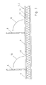
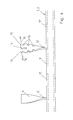
- FIG. 5 and 6 show appropriate installation situations, with the detail after FIG. 5 in FIG. 9 is shown and the detail after FIG. 6 in FIG. 8 is shown.
- FIG. 5 shows that in the interior of the anchor rail 1, a profile sheet 21 can be inserted, which is formed in the embodiment shown as a U-profile.
- This profile sheet 21 is adapted to receive a drill screw 22 which is screwed with a self-tapping thread in the material of the profile sheet 21.
- This drill screw for example, fastened a sheet metal rail 23, which is part of the so-called cladding profile 28 (floor suitcase).
- FIG. 6 shows further details of the attachment of the trim profile 28. It can be seen that the sheet metal rail 23 is formed as a U-profile and is screwed onto the underside of the precast panels 24, 26.
- FIG. 5 shows in a conventional manner that in the prefabricated panels 24, 26 reinforcing rods 19, 20 are introduced and that the precast panels 24, 26 are formed entirely of concrete elements 18. It follows that the installation of such anchor rail 1 is not necessary to take place only in prefabricated panels 24, 26, but in any such anchor channels any concrete elements 18 can be introduced.
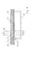
- FIG. 7 is a ceiling composite of 2 prefabricated panels 24, 26 shown in plan view. It can be seen that in one precast panel 24 the Anchor rails 1 protrude inward over a wide extent and protrude into a corridor 27 and beyond that beyond a parting line 25, the anchor rails 1 projecting from the other precast slab 26 protrude into the area of the parting line 27.
- the two opposing anchor channels 1 of the two flush mounted in the same plane precast panels 24, 26 thus meet in the region of the parting line 25th
- FIG. 8 shows, moreover, that in the corridor area still a support 29 is arranged, which penetrates the corridor area. Accordingly, it is important in the present invention that the anchor rails 1 are also formed to 2/3 of the material of the right precast panel 24 and 1/3 of the material of the precast panel 26, wherein these two prefabricated panels 24, 26 in the region of the parting line 25 meet and abut each other there.
- anchor rails 1 arranged in this area form a favorable attachment for elements to be arranged and suspended in the corridor 27, such elements being designed, for example, only as a trim profile 28.
- the piping for the heater, power lines, ventilation ducts and the like can be performed.
Landscapes
- Engineering & Computer Science (AREA)
- Architecture (AREA)
- Physics & Mathematics (AREA)
- Electromagnetism (AREA)
- Civil Engineering (AREA)
- Structural Engineering (AREA)
- Joining Of Building Structures In Genera (AREA)
Applications Claiming Priority (1)
| Application Number | Priority Date | Filing Date | Title |
|---|---|---|---|
| DE200910059885 DE102009059885A1 (de) | 2009-12-21 | 2009-12-21 | Ankerschiene zum Einbetonieren in Beton |
Publications (2)
| Publication Number | Publication Date |
|---|---|
| EP2336441A2 true EP2336441A2 (fr) | 2011-06-22 |
| EP2336441A3 EP2336441A3 (fr) | 2014-02-26 |
Family
ID=43569487
Family Applications (1)
| Application Number | Title | Priority Date | Filing Date |
|---|---|---|---|
| EP10015807.0A Withdrawn EP2336441A3 (fr) | 2009-12-21 | 2010-12-20 | Rail d'ancrage pour couler dans le béton |
Country Status (2)
| Country | Link |
|---|---|
| EP (1) | EP2336441A3 (fr) |
| DE (1) | DE102009059885A1 (fr) |
Cited By (1)
| Publication number | Priority date | Publication date | Assignee | Title |
|---|---|---|---|---|
| AT513575A1 (de) * | 2012-11-05 | 2014-05-15 | Omv Austria Exploration & Production Gmbh | Vorrichtung zur Befestigung eines Rahmenelements einer Maschine |
Families Citing this family (2)
| Publication number | Priority date | Publication date | Assignee | Title |
|---|---|---|---|---|
| DE102013012612A1 (de) | 2013-07-26 | 2015-02-19 | Rainer Förster | Montagevorrichtung zur Realisierung eines Ankerschienensystems in einer Grube für Ankerschienen |
| DE202013006831U1 (de) | 2013-07-26 | 2013-08-14 | Rainer Förster | Montagevorrichtung zur Realisierung eines Ankerschienensystems in einer Grube für Ankerschienen |
Family Cites Families (5)
| Publication number | Priority date | Publication date | Assignee | Title |
|---|---|---|---|---|
| FR1570146A (fr) * | 1967-10-20 | 1969-06-06 | ||
| GB2193513A (en) * | 1986-08-05 | 1988-02-10 | Harris & Edgar Limited | A channel and wall tie |
| GB8808808D0 (en) * | 1988-04-14 | 1988-05-18 | Vantrunk Eng Ltd | Insert for channel section member |
| US4948313A (en) * | 1988-11-23 | 1990-08-14 | Wesanco, Inc. | Nut platform for framing channels |
| US7237368B2 (en) * | 2002-05-24 | 2007-07-03 | Richard B. Richardson | Adjustable anchoring system for a wall |
-
2009
- 2009-12-21 DE DE200910059885 patent/DE102009059885A1/de not_active Withdrawn
-
2010
- 2010-12-20 EP EP10015807.0A patent/EP2336441A3/fr not_active Withdrawn
Non-Patent Citations (1)
| Title |
|---|
| None |
Cited By (2)
| Publication number | Priority date | Publication date | Assignee | Title |
|---|---|---|---|---|
| AT513575A1 (de) * | 2012-11-05 | 2014-05-15 | Omv Austria Exploration & Production Gmbh | Vorrichtung zur Befestigung eines Rahmenelements einer Maschine |
| AT513575B1 (de) * | 2012-11-05 | 2015-06-15 | Omv Austria Exploration & Production Gmbh | Vorrichtung zur Befestigung eines Rahmenelements einer Maschine |
Also Published As
| Publication number | Publication date |
|---|---|
| EP2336441A3 (fr) | 2014-02-26 |
| DE102009059885A1 (de) | 2011-06-22 |
Similar Documents
| Publication | Publication Date | Title |
|---|---|---|
| EP0641901B1 (fr) | Système de montage ou de construction pour une maison en bois | |
| DE3310931A1 (de) | Tragschiene und traggitter fuer abgehaengte decken sowie eine abgehaengte decke | |
| EP2163699B1 (fr) | Profilé de raccord | |
| DE3326174A1 (de) | Befestigungsvorrichtung | |
| EP2075388A1 (fr) | Eléments d'armature et pièces en béton armé ou précontraint ainsi produites avec ces éléments d'armature | |
| EP2336441A2 (fr) | Rail d'ancrage pour couler dans le béton | |
| DE102005005745B3 (de) | Profilplatte zum Eindecken eines Gebäudedachs sowie Gebäudedach | |
| DE3909803C2 (de) | Industriefußboden aus Betonplatten | |
| DE102020114611B3 (de) | Schalungsanordnung | |
| DE19743846C2 (de) | Sattel- oder Krüppelwalmdach | |
| CH718328B1 (de) | Abschalleiste, Überdeckungsabschalung, Abschalungselement, Schalungsanordnung, Verfahren zum Aufbau einer Schalungsanordnung und Verfahren zum Herstellen einer Abschalleiste. | |
| EP1936054B9 (fr) | Languette de traction destinée à la fixation de plaques murales en béton poreux, ainsi que système de plaques murales en béton poreux doté de languettes de traction | |
| DE1275756B (de) | Wandverkleidung aus schweren, aus Stein od. dgl. bestehenden Verkleidungsplatten | |
| EP2299017B1 (fr) | Elément de coffrage en plusieurs parties destiné à la création d'un joint de construction | |
| AT522366B1 (de) | Bewehrungselement, Betonbauelement und Verfahren zum Herstellen eines Betonbauelements | |
| DE102019133384B4 (de) | Bewehrungsanschlussanordnung | |
| EP1932978A1 (fr) | Elément d'armature pour l'absorption de forces dans des plaques de béton dans la zone d'éléments d'appui | |
| EP0121101B1 (fr) | Structure de couverture | |
| DE29617673U1 (de) | Abschalelement | |
| DE102006038058A1 (de) | Verfahren zur Herstellung eines modular aufgebauten Stahlwagenkastens sowie modularer Bausatz zur Durchführung des Verfahrens | |
| DE1484056C (de) | Unterdecke | |
| DE102014113973A1 (de) | Fugenelement zur Abdichtung von Stoß- und/oder Eckfugen | |
| DE10013703C2 (de) | Vorrichtung zur Schaustellung von Produkten für das Bauwesen | |
| EP4194613A1 (fr) | Module de fabrication d'une fondation en béton, utilisation et procédé | |
| DE202020103150U1 (de) | Schalungsanordnung |
Legal Events
| Date | Code | Title | Description |
|---|---|---|---|
| PUAI | Public reference made under article 153(3) epc to a published international application that has entered the european phase |
Free format text: ORIGINAL CODE: 0009012 |
|
| AK | Designated contracting states |
Kind code of ref document: A2 Designated state(s): AL AT BE BG CH CY CZ DE DK EE ES FI FR GB GR HR HU IE IS IT LI LT LU LV MC MK MT NL NO PL PT RO RS SE SI SK SM TR |
|
| AX | Request for extension of the european patent |
Extension state: BA ME |
|
| PUAL | Search report despatched |
Free format text: ORIGINAL CODE: 0009013 |
|
| AK | Designated contracting states |
Kind code of ref document: A3 Designated state(s): AL AT BE BG CH CY CZ DE DK EE ES FI FR GB GR HR HU IE IS IT LI LT LU LV MC MK MT NL NO PL PT RO RS SE SI SK SM TR |
|
| AX | Request for extension of the european patent |
Extension state: BA ME |
|
| RIC1 | Information provided on ipc code assigned before grant |
Ipc: E04B 1/41 20060101AFI20140121BHEP |
|
| STAA | Information on the status of an ep patent application or granted ep patent |
Free format text: STATUS: THE APPLICATION IS DEEMED TO BE WITHDRAWN |
|
| 18D | Application deemed to be withdrawn |
Effective date: 20140827 |