EP2336518A2 - Dispositif de traitement des gaz d'échappement - Google Patents
Dispositif de traitement des gaz d'échappement Download PDFInfo
- Publication number
- EP2336518A2 EP2336518A2 EP10187756A EP10187756A EP2336518A2 EP 2336518 A2 EP2336518 A2 EP 2336518A2 EP 10187756 A EP10187756 A EP 10187756A EP 10187756 A EP10187756 A EP 10187756A EP 2336518 A2 EP2336518 A2 EP 2336518A2
- Authority
- EP
- European Patent Office
- Prior art keywords
- tube
- strips
- curved
- treatment device
- wall
- Prior art date
- Legal status (The legal status is an assumption and is not a legal conclusion. Google has not performed a legal analysis and makes no representation as to the accuracy of the status listed.)
- Granted
Links
Images

Classifications
-
- F—MECHANICAL ENGINEERING; LIGHTING; HEATING; WEAPONS; BLASTING
- F01—MACHINES OR ENGINES IN GENERAL; ENGINE PLANTS IN GENERAL; STEAM ENGINES
- F01N—GAS-FLOW SILENCERS OR EXHAUST APPARATUS FOR MACHINES OR ENGINES IN GENERAL; GAS-FLOW SILENCERS OR EXHAUST APPARATUS FOR INTERNAL-COMBUSTION ENGINES
- F01N13/00—Exhaust or silencing apparatus characterised by constructional features
- F01N13/18—Construction facilitating manufacture, assembly, or disassembly
- F01N13/1805—Fixing exhaust manifolds, exhaust pipes or pipe sections to each other, to engine or to vehicle body
- F01N13/1811—Fixing exhaust manifolds, exhaust pipes or pipe sections to each other, to engine or to vehicle body with means permitting relative movement, e.g. compensation of thermal expansion or vibration
-
- F—MECHANICAL ENGINEERING; LIGHTING; HEATING; WEAPONS; BLASTING
- F01—MACHINES OR ENGINES IN GENERAL; ENGINE PLANTS IN GENERAL; STEAM ENGINES
- F01N—GAS-FLOW SILENCERS OR EXHAUST APPARATUS FOR MACHINES OR ENGINES IN GENERAL; GAS-FLOW SILENCERS OR EXHAUST APPARATUS FOR INTERNAL-COMBUSTION ENGINES
- F01N13/00—Exhaust or silencing apparatus characterised by constructional features
- F01N13/08—Other arrangements or adaptations of exhaust conduits
-
- F—MECHANICAL ENGINEERING; LIGHTING; HEATING; WEAPONS; BLASTING
- F01—MACHINES OR ENGINES IN GENERAL; ENGINE PLANTS IN GENERAL; STEAM ENGINES
- F01N—GAS-FLOW SILENCERS OR EXHAUST APPARATUS FOR MACHINES OR ENGINES IN GENERAL; GAS-FLOW SILENCERS OR EXHAUST APPARATUS FOR INTERNAL-COMBUSTION ENGINES
- F01N13/00—Exhaust or silencing apparatus characterised by constructional features
- F01N13/18—Construction facilitating manufacture, assembly, or disassembly
- F01N13/1805—Fixing exhaust manifolds, exhaust pipes or pipe sections to each other, to engine or to vehicle body
- F01N13/1811—Fixing exhaust manifolds, exhaust pipes or pipe sections to each other, to engine or to vehicle body with means permitting relative movement, e.g. compensation of thermal expansion or vibration
- F01N13/1816—Fixing exhaust manifolds, exhaust pipes or pipe sections to each other, to engine or to vehicle body with means permitting relative movement, e.g. compensation of thermal expansion or vibration the pipe sections being joined together by flexible tubular elements only, e.g. using bellows or strip-wound pipes
-
- F—MECHANICAL ENGINEERING; LIGHTING; HEATING; WEAPONS; BLASTING
- F01—MACHINES OR ENGINES IN GENERAL; ENGINE PLANTS IN GENERAL; STEAM ENGINES
- F01N—GAS-FLOW SILENCERS OR EXHAUST APPARATUS FOR MACHINES OR ENGINES IN GENERAL; GAS-FLOW SILENCERS OR EXHAUST APPARATUS FOR INTERNAL-COMBUSTION ENGINES
- F01N13/00—Exhaust or silencing apparatus characterised by constructional features
- F01N13/18—Construction facilitating manufacture, assembly, or disassembly
- F01N13/1838—Construction facilitating manufacture, assembly, or disassembly characterised by the type of connection between parts of exhaust or silencing apparatus, e.g. between housing and tubes, between tubes and baffles
- F01N13/1844—Mechanical joints
- F01N13/185—Mechanical joints the connection being realised by deforming housing, tube, baffle, plate, or parts thereof
-
- F—MECHANICAL ENGINEERING; LIGHTING; HEATING; WEAPONS; BLASTING
- F01—MACHINES OR ENGINES IN GENERAL; ENGINE PLANTS IN GENERAL; STEAM ENGINES
- F01N—GAS-FLOW SILENCERS OR EXHAUST APPARATUS FOR MACHINES OR ENGINES IN GENERAL; GAS-FLOW SILENCERS OR EXHAUST APPARATUS FOR INTERNAL-COMBUSTION ENGINES
- F01N2470/00—Structure or shape of exhaust gas passages, pipes or tubes
- F01N2470/02—Tubes being perforated
-
- F—MECHANICAL ENGINEERING; LIGHTING; HEATING; WEAPONS; BLASTING
- F01—MACHINES OR ENGINES IN GENERAL; ENGINE PLANTS IN GENERAL; STEAM ENGINES
- F01N—GAS-FLOW SILENCERS OR EXHAUST APPARATUS FOR MACHINES OR ENGINES IN GENERAL; GAS-FLOW SILENCERS OR EXHAUST APPARATUS FOR INTERNAL-COMBUSTION ENGINES
- F01N2470/00—Structure or shape of exhaust gas passages, pipes or tubes
- F01N2470/24—Concentric tubes or tubes being concentric to housing, e.g. telescopically assembled
Definitions
- the present invention relates to an exhaust gas treatment device for an exhaust system of an internal combustion engine, in particular of a road vehicle.
- An exhaust treatment device may, for. B. as a catalyst or as a particulate filter or as a silencer or comprise any combination of such devices.
- such an exhaust gas treatment device usually has a housing which encloses at least one interior space.
- this passage tube is then held at two spaced locations in the housing. For example. passes through the through-tube two spaced bottoms of the housing, which stabilize the passage tube laterally.
- the passage tube To reduce or avoid stresses between the passage tube and the housing due to thermally induced expansion effects, it is customary to attach the passage tube only at one bottom, while it is held axially movable on the other floor via a sliding seat.
- the present invention is concerned with the problem, for an exhaust gas treatment device in which a continuous tube assembly is supported in a housing, to provide an improved or at least another embodiment, which is particularly characterized in that it avoids at least one of the aforementioned disadvantages of a sliding seat solution.
- the present invention is based on the general idea to provide a wall of the respective tube with strips which are adjacent to each other in the circumferential direction, which are designed to be resilient radially to the longitudinal central axis of the respective tube and thereby protrude from the rest of the tube to the outside or inwards.
- the strips thereby form elements which are elastically resilient in the radial direction.
- This can be used according to a first solution of the present invention to cushion axial forces that can attack the through-ear when it is, for example, on both sides of the strip-equipped area fixedly connected to the housing.
- the elastic strips enable the realization of a sliding seat in which one tube is supported on the other tube by radial prestressing via the radially elastic strips.
- the at least one through-tube is fixedly connected to the housing at two fastening points which are remote from one another, and has at least one expansion-compensating section between these fastening points which has said elastic strips.
- the expansion compensation section in a wall of the passage tube slots and strips are formed which alternate in the circumferential direction. As the slots penetrate the wall of the passageway, the strips project toward adjacent wall portions of the passageway.
- the housing of the exhaust gas treatment device comprises two pipes mounted longitudinally displaceably via a sliding seat, wherein one of the pipes in the sliding seat has a spring section which has the resilient strips.
- a wall of the respective tube has a plurality of circumferentially adjacent strips, which abut radially resiliently on the other tube with respect to the longitudinal central axis of the tube prevailing in the spring section.
- the strips may be formed by the fact that the wall in the spring section is interrupted in the circumferential direction by a plurality of slots penetrating the wall, while the strips project with respect to adjacent wall sections of the respective tube.
- this spring section can be designed basically identical to the expansion compensation section of the first solution.
- the strips of the spring section in that in the spring section in the wall adjacent in the circumferential direction, a plurality of strip-shaped wall sections are cut free and exhibited.
- the respective free-cutting contour summarizes the respective strip-shaped wall section on three sides, while it only remains firmly connected to the remaining wall of the pipe on the fourth side. By reshaping the thus far cut wall section is issued.
- the slots each define only one side of adjacent strips. Also, there the strips are connected at two spaced apart sides in the region of the slot ends each fixed to the wall of the passage tube.
- the strips can be curved in a wavy or zigzag-shaped manner.
- a wave-shaped curvature is preferred because there the risk of excessive voltage peaks is reduced in a compact design.
- the strips can be curved in a simple or two-dimensional manner, so that they are curved only with respect to a longitudinal direction of the respective tube.
- the strips may be curved twice or three-dimensionally, so that they are arched both in the longitudinal direction and transversely thereto, ie in the circumferential direction.
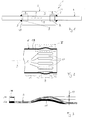
- an exhaust gas treatment device 1 comprises a housing 2, which encloses at least one inner space 3.
- the exhaust gas treatment device 1 is provided for an - here only partially recognizable - exhaust system 4 of an internal combustion engine, which may be arranged in particular in a road vehicle.
- the exhaust gas treatment device 1 may be a catalyst such.
- an oxidation catalyst or a NOX storage catalyst or an SCR catalyst Likewise, the exhaust gas treatment device 1 may be a particle filter, in particular a soot filter.
- the exhaust gas treatment device 1 may be a silencer. Likewise, it may be a basically arbitrary combination of catalyst, particulate filter and / or muffler. In particular, the show Fig. 1 and 4 in each case only a part of the exhaust gas treatment device 1.
- the exhaust gas treatment device 1 has at least one through-tube 5, which is passed through the interior 3 without interruption, thus interspersing the interior 3 without interruption. Further, the passage tube 5 is fixedly connected to the housing 2 at two attachment points 6 and 7 remote from each other.
- the fastening points 6, 7 can be realized by welded joints.
- the passage tube 5 has at least one expansion compensation section 8, which in Fig. 1 indicated by a curly bracket. Concerning. a longitudinal center axis 9 of the passage tube fifth the expansion compensation section 8 is a longitudinal section or axial section. In the example of Fig. 1 two such expansion compensation sections 8 are indicated, which can be realized alternatively or cumulatively.
- the respective expansion compensation section 8 is characterized in that a wall 10 of the through-tube 5 has a plurality of strips 11 and a plurality of slots 12 therein, which alternate in the circumferential direction relative to the longitudinal axis 9.
- the slits 12 penetrate the wall 10.
- the strips 11 project relative to adjacent wall sections 13 and 14 of the through-tube 5.
- the strips 11 are geometrically shaped so that they absorb elastic forces acting in the passage tube 5 tensile and compressive forces. Such forces can be introduced via the attachment points 6, 7 in the passage tube 5. For example. Thermally induced elongation effects can cause the passage tube 5 expands faster and / or stronger than the housing 2, which can lead to the said forces.
- FIGS. 2 and 3 the strips 11 are undulating and simply curved outwards.
- Fig. 3 illustrates the operation of the strips 11.
- a indicated by an arrow 15 pressing force 15 leads to a compression 16 of the passage tube 5.
- the strips 11 can elastically bulge and thereby perform a stroke 17 which compensates the compression 16 and the compression force 15 resiliently receives. If the pressure force 15 goes back, the compression 16 also decreases, as a result of which the stroke 17 also decreases elastically. The same applies vice versa for tensile forces.
- Fig. 1 are the attachment points 6, 7 on the housing side 2 provided at end bottoms 34, 35 of the housing 2. It is clear that at another Configuration, the floors 34, 35 also inside, so in the interior of the housing 2 arranged floors can be.
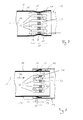
- Fig. 4 shows another embodiment of the exhaust treatment device 1. It differs from the in Fig. 1 shown embodiment in that no two attachment points 6, 7 fixed to the housing 2 through pipe 5 is present, but that in the housing 2, two tubes 18, 19 are mounted longitudinally displaceable via a sliding seat 20 together.
- the one tube 18, which is also referred to below as the first tube 18, can be fixedly connected to the housing 2 via an attachment point 21.
- the fastening point 21 can be realized, for example, by means of a welded connection.
- the other tube 19, which is also referred to below as the second tube 19, may also be fixedly attached to the housing 2.
- the two tubes 18, 19 are inserted into the sliding seat 20 coaxially with each other.
- This in Fig. 4 shorter second tube 19 may also be formed by a pipe socket which is formed on a wall 33 of the housing 2.
- This pipe socket 19 may be integrally formed on this wall 33.
- One of the tubes 18, 19 has in the sliding seat 20 on a spring portion 22 which in Fig. 4 indicated by a curly bracket.
- This spring section 22 is characterized in that it has a plurality of strips, which are also referred to below as 11. These strips 11 are arranged adjacent to the longitudinal axis 9 in the circumferential direction. Furthermore, they are designed resiliently with respect to the longitudinal central axis 9 in the radial direction. Furthermore, they rest on the respective other tube 18, 19 in particular under radial prestress.
- the first tube 18 equipped with this spring portion 22.
- the first tube 18 is inserted into the second tube 19 and thus forms an inner tube 18 in the sliding seat 20.
- the strips 11 are then shaped in these embodiments so that they protrude outwardly from the first tube 18 and on the outer second Tube 19 come radially biased to the plant.
- Fig. 7 another embodiment in which the first tube 18 is fitted externally on the second tube 19 and accordingly forms the outer tube 18 in the sliding seat 20.
- the strips 11 are shaped so that they protrude inwards towards the inner second tube 19 and come to rest radially biased.
- the shaping of the strips 11 refers Fig. 7 to the embodiment of the Fig. 5 , It is clear that this configuration with inwardly biased strips 11 also in the in Fig. 8 shown embodiment of the strip 11 is realized.
- Fig. 6 refers to the in Fig. 5 embodiment shown, but is analogous to the in the FIGS. 7 and 8 shown embodiments applicable.
- the strips 11 are geometrically shaped so that they define before the piercing of the tubes 18, 19 in the sliding seat 20 in the spring portion 22 an outer perimeter whose cross-section is greater than the free cross section of the second tube 19, in which with the spring portion 22nd equipped first tube 18 is to be inserted. If the first tube 18 as in Fig. 7 is to be plugged onto the second tube 19, the strips 11 are then analogously shaped so that prior to mating of the tubes 18, 19 in the sliding seat 20 they define an inner perimeter whose cross section is smaller than the outer cross section of the second tube nineteenth
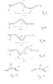
- FIGS. 13 and 14 may optionally be provided to bend the respective strip 11 not only simple, but twice or buckle.
- the simply curved or only two-dimensionally curved strips 11 are curved or arched only with respect to the longitudinal direction.
- the double-curved or three-dimensionally curved strips 11 are additionally curved or arched relative to the circumferential direction. This is so realizable with all sliding seats 20.
- the curvature or curvature with respect to the circumferential direction is in the FIGS. 13 and 14 denoted by 37.
- the vault 37 has two turning points.
- profile of Fig. 14 the bulge 37 is non-pointing.
- the shape of the strips 11 causes the strips 11 to contact the respective other tube 19 only over comparatively small contact surfaces 26. This significantly reduces friction on the one hand. On the other hand, the risk of jamming of the two tubes 18, 19 in the sliding seat 20 is considerably reduced.
- the respective contact surface 26 is smaller than a surface 36 of the respective strip 11, which faces the other tube 19.
- the contact surface 26 of the respective strip 11 occupies a maximum of 30% or a maximum of 25% or a maximum of 20% or a maximum of 15% or a maximum of 10% or a maximum of 5% of the surface 36 of the respective strip 11.
- a simple curvature or curvature of the respective strip 11 a reduction of the respective contact surface 26 to a line extending in the circumferential direction is preferred. If the curvature or curvature of the respective strip 11 is realized twice or three-dimensionally, the respective contact surface 26 preferably reduces to one point.
- the strips 11 are realized in that a wall, which is also referred to below as 10, of the respective tube, here the first tube 18 in the spring section 22 is interrupted by a plurality of slots, will also be referred to below as 12.
- the slots 12 penetrate the wall 10.
- the slots 12 and the strips 11 alternate in the circumferential direction.
- the spring portion 22 is formed on the inside of the sliding seat 20 tube 18 so that the strips 11 project outwardly.
- the spring portion 22 at the in Fig. 7 shown embodiment formed on the outside in the sliding seat 20 tube 18 so that there the strips 11 protrude inwards.
- Fig. 8 now shows another embodiment for the realization of the spring portion 22.
- the strips 11 are realized by that in the spring section 22 in a wall, which is also referred to below as 10, the respective tube, here the first tube 18, a plurality of strip-shaped wall sections 27 are cut free by means of cuts 28 and issued.
- the cuts 28 may be designed in particular U-shaped. In any case, they enclose the strip-shaped wall portions 27 from three sides, whereby the wall portions 27 can be exposed to form the strips 11.
- further strip-shaped wall portions 29 are present, which connect to the spring portion 22 adjacent wall portions of the tube 18, which are also designated here with 13 and 14 with each other.
- Such strip-shaped wall portions 29, which connect the adjacent wall sections 13, 14 with each other and which are present in addition to the issued strip 11, missing in the in the Fig. 5 to 7 shown embodiments. There assume this connection function, the strips 11, which are connected to two adjacent wall sections 13, 14.
- the spring portion 22 is formed on the inside of the sliding seat 20 tube 18 so that the strips 11 are issued to the outside.
- the respective passage tube 5 or the respective tube 18, 19 has in the embodiments shown outside of the expansion compensation section 8 or outside the spring portion 22 purely by way of example in each case a constant cross section. It is clear that in other embodiments here also varying cross sections can be realized. In particular, the respective tube 5, 18, 19 may also be a funnel.
- the strips 11 are undulating and simply curved irrespective of their form of realization.
- the Fig. 9 to 12 indicate other geometries for the strips 11, but without claim to completeness.
- the in the Fig. 9 to 12 shown different shapes for the strips 11 are also feasible within the expansion compensation section 8 as in the spring section 22. Also, they are not only for the both sides connected to the wall 10 strips 11 of the embodiments according to the Fig. 2 . 5 and 7 feasible, but also for the only one side connected to the wall 10 strip 11 of the embodiment according to Fig. 8 ,
- Fig. 9 a doubly wavy curved strip 11 having an outwardly curved or outwardly projecting portion 31 and an inwardly curved or inwardly projecting portion 32;
- the 10 and 11 each show a strip 11 which is bent or bent in a zigzag shape.
- the strip 11 is bent outward or angled while in Fig. 11 angled or bent inwards.
- the strip in the 10 and 11 in each case only simply bent zigzag-shaped, shows Fig. 12 a variant in which the strip 11 is bent or angled twice in a zig-zag shape.
- the strip 11 thus again has an outwardly bent or outwardly projecting region 31 and an inwardly bent or inwardly projecting region 32.
- the strips 11 each extend parallel to the longitudinal central axis 9.
- the slots 12 extend parallel to the longitudinal center axis 9.
- the strips 11 and, accordingly, the slots 12 with respect to the longitudinal central axis 9 may extend inclined, such that they extend, for example, thread-like and z. B. have a slope.
- the strips 11 are integrally formed on the respective tube 5, 18. Basically, however, an embodiment is conceivable in which the strips 11 are separate components which are attached to the respective pipe 5, 18.
Landscapes
- Engineering & Computer Science (AREA)
- Chemical & Material Sciences (AREA)
- Combustion & Propulsion (AREA)
- Mechanical Engineering (AREA)
- General Engineering & Computer Science (AREA)
- Exhaust Silencers (AREA)
- Exhaust Gas After Treatment (AREA)
Applications Claiming Priority (1)
| Application Number | Priority Date | Filing Date | Title |
|---|---|---|---|
| DE200910059684 DE102009059684A1 (de) | 2009-12-19 | 2009-12-19 | Abgasbehandlungseinrichtung |
Publications (3)
| Publication Number | Publication Date |
|---|---|
| EP2336518A2 true EP2336518A2 (fr) | 2011-06-22 |
| EP2336518A3 EP2336518A3 (fr) | 2012-05-30 |
| EP2336518B1 EP2336518B1 (fr) | 2017-06-21 |
Family
ID=43662237
Family Applications (1)
| Application Number | Title | Priority Date | Filing Date |
|---|---|---|---|
| EP10187756.1A Active EP2336518B1 (fr) | 2009-12-19 | 2010-10-15 | Dispositif de traitement des gaz d'échappement |
Country Status (5)
| Country | Link |
|---|---|
| US (2) | US8925308B2 (fr) |
| EP (1) | EP2336518B1 (fr) |
| JP (1) | JP5902386B2 (fr) |
| CN (1) | CN102102570B (fr) |
| DE (1) | DE102009059684A1 (fr) |
Cited By (1)
| Publication number | Priority date | Publication date | Assignee | Title |
|---|---|---|---|---|
| EP3822463A1 (fr) * | 2019-11-14 | 2021-05-19 | Eberspächer Exhaust Technology GmbH | Composant d'échappement doté d'un pont à persiennes pour supprimer les résonances d'un tuyau d'échappement de véhicule et système d'échappement de véhicule comportant le composant d'échappement |
Families Citing this family (6)
| Publication number | Priority date | Publication date | Assignee | Title |
|---|---|---|---|---|
| US8234859B2 (en) * | 2005-07-08 | 2012-08-07 | Ng1 Technologies, Llc | Method of and apparatus for exhausting internal combustion engines |
| DE102012015667A1 (de) * | 2012-08-09 | 2014-04-30 | L'Air Liquide, Société Anonyme pour l'Etude et l'Exploitation des Procédés Georges Claude | Austrittssystem für einen Dampfreformer und Lagerung hierfür |
| DE102014110101A1 (de) * | 2014-07-18 | 2016-01-21 | Friedrich Boysen Gmbh & Co. Kg | Schalldämpfer |
| DE102015113159A1 (de) * | 2015-08-10 | 2017-02-16 | Faurecia Emissions Control Technologies, Germany Gmbh | Bauteil einer Abgasanlage |
| KR20200034564A (ko) | 2018-09-20 | 2020-03-31 | 주식회사 제우스 | 플로우셀장치 |
| JP7485513B2 (ja) | 2020-01-06 | 2024-05-16 | フタバ産業株式会社 | 排気管 |
Family Cites Families (33)
| Publication number | Priority date | Publication date | Assignee | Title |
|---|---|---|---|---|
| US1993397A (en) * | 1930-10-10 | 1935-03-05 | Michigan Steel Tube Products C | Exhaust conduit and muffler for an automotive vehicle |
| US2251369A (en) * | 1939-05-03 | 1941-08-05 | Walker Mfg Co | Silencer |
| US2213614A (en) * | 1939-05-18 | 1940-09-03 | Winthrop T Scarritt | Muffler |
| US3196976A (en) * | 1963-06-27 | 1965-07-27 | Walker Mfg Co | Muffler having outer shell deformed to define chambers around center tube |
| US3262516A (en) * | 1964-03-09 | 1966-07-26 | Otto F Borgeson | Multi-passage muffler insert for exhaust pipe |
| US3415336A (en) * | 1966-11-14 | 1968-12-10 | Arvin Ind Inc | Resonator and method of making it |
| US3523590A (en) * | 1968-12-18 | 1970-08-11 | Tenneco Inc | Simplified muffler shell construction |
| DE1933339A1 (de) * | 1969-07-01 | 1971-01-21 | Friedrich Boysen | Vorrichtung an Absorptions-Schalldaempfern |
| JPS59102919A (ja) | 1982-12-02 | 1984-06-14 | Dainippon Ink & Chem Inc | 水溶性樹脂組成物 |
| JPS59102919U (ja) * | 1982-12-28 | 1984-07-11 | カルソニックカンセイ株式会社 | 機関用消音器 |
| JPS6057716U (ja) * | 1983-09-29 | 1985-04-22 | 三菱自動車工業株式会社 | 車両用消音器 |
| DE4009201A1 (de) * | 1990-01-25 | 1991-08-01 | Man Technologie Gmbh | Abgassystem mit einem partikelfilter und einem regenerierungsbrenner |
| DE9102926U1 (de) * | 1991-03-12 | 1991-08-08 | Leistritz AG & Co Abgastechnik, 8510 Fürth | Luftspaltisoliertes Vorrohr |
| JPH05916U (ja) * | 1991-06-24 | 1993-01-08 | カルソニツク株式会社 | 吸音型消音器 |
| EP0662564B2 (fr) * | 1994-01-07 | 2001-09-26 | J. Eberspächer GmbH & Co. | Conduit de gaz d'échappement isolé par une couche d'air et méthode de construction |
| JPH0868319A (ja) * | 1994-08-26 | 1996-03-12 | Toyota Motor Corp | 排気二重管構造 |
| JPH0882210A (ja) * | 1994-09-13 | 1996-03-26 | Daihatsu Motor Co Ltd | 排気消音器 |
| JPH08218860A (ja) | 1995-02-17 | 1996-08-27 | Nissan Motor Co Ltd | 二重排気管 |
| JPH09195799A (ja) * | 1996-01-17 | 1997-07-29 | Mitsubishi Heavy Ind Ltd | 燃焼器のスプリングシール装置 |
| DE19811599C2 (de) * | 1998-03-17 | 2002-01-10 | Framatome Anp Gmbh | Rohr mit einem Aufweitbereich |
| JP2002266623A (ja) * | 2001-03-09 | 2002-09-18 | Futaba Industrial Co Ltd | 内燃機関用消音器 |
| JP2004036402A (ja) * | 2002-06-28 | 2004-02-05 | Nissan Motor Co Ltd | 車両用消音装置 |
| JP2004316564A (ja) * | 2003-04-17 | 2004-11-11 | Apex:Kk | 消音器 |
| US6826834B2 (en) * | 2003-02-21 | 2004-12-07 | I-Long Wu | Manufacturing method of a muffler assembly |
| DE10339290A1 (de) * | 2003-08-27 | 2005-04-07 | J. Eberspächer GmbH & Co. KG | Schalldämpfer sowie Abgasanlage |
| JP2005233167A (ja) * | 2004-02-23 | 2005-09-02 | Calsonic Kansei Corp | 自動車用サブマフラ |
| US6889500B1 (en) * | 2004-03-01 | 2005-05-10 | Roy Martinez | Engine exhaust extractor |
| DE102004018693B4 (de) * | 2004-04-17 | 2007-09-06 | Daimlerchrysler Ag | Abgasanlage |
| US7448133B2 (en) * | 2004-09-23 | 2008-11-11 | Honeywell International Inc. | Procedure for replacement of acoustic liner in integrated exhaust duct muffler for use with airborne auxiliary power units |
| DE102006011091A1 (de) * | 2006-03-08 | 2007-09-13 | J. Eberspächer GmbH & Co. KG | Komponente einer Abgasanlage |
| JP2008240586A (ja) * | 2007-03-27 | 2008-10-09 | Calsonic Kansei Corp | 車両用消音器 |
| US8020272B2 (en) * | 2007-04-20 | 2011-09-20 | GM Global Technology Operations LLC | Method for joining tubes |
| DE102007062662A1 (de) * | 2007-12-24 | 2009-06-25 | J. Eberspächer GmbH & Co. KG | Schiebesitz und Abgasbehandlungseinrichtung |
-
2009
- 2009-12-19 DE DE200910059684 patent/DE102009059684A1/de not_active Withdrawn
-
2010
- 2010-10-15 EP EP10187756.1A patent/EP2336518B1/fr active Active
- 2010-11-03 US US12/938,765 patent/US8925308B2/en active Active
- 2010-12-08 CN CN201010578242.0A patent/CN102102570B/zh active Active
- 2010-12-17 JP JP2010281498A patent/JP5902386B2/ja active Active
-
2014
- 2014-08-14 US US14/459,746 patent/US9228478B2/en active Active
Non-Patent Citations (1)
| Title |
|---|
| None |
Cited By (2)
| Publication number | Priority date | Publication date | Assignee | Title |
|---|---|---|---|---|
| EP3822463A1 (fr) * | 2019-11-14 | 2021-05-19 | Eberspächer Exhaust Technology GmbH | Composant d'échappement doté d'un pont à persiennes pour supprimer les résonances d'un tuyau d'échappement de véhicule et système d'échappement de véhicule comportant le composant d'échappement |
| US11300021B2 (en) | 2019-11-14 | 2022-04-12 | Purem Novi, Inc. | Exhaust component with louver bridge for suppressing vehicle exhaust pipe resonances and vehicle exhaust system with exhaust component |
Also Published As
| Publication number | Publication date |
|---|---|
| DE102009059684A1 (de) | 2011-06-22 |
| US20110146255A1 (en) | 2011-06-23 |
| CN102102570A (zh) | 2011-06-22 |
| US9228478B2 (en) | 2016-01-05 |
| EP2336518A3 (fr) | 2012-05-30 |
| US8925308B2 (en) | 2015-01-06 |
| EP2336518B1 (fr) | 2017-06-21 |
| JP5902386B2 (ja) | 2016-04-13 |
| JP2011127607A (ja) | 2011-06-30 |
| CN102102570B (zh) | 2019-06-07 |
| US20140352287A1 (en) | 2014-12-04 |
Similar Documents
| Publication | Publication Date | Title |
|---|---|---|
| EP2336518B1 (fr) | Dispositif de traitement des gaz d'échappement | |
| EP0432436B1 (fr) | Elément de conduite flexible pour tyaux d'échappement de moteurs de véhicules à combustion interne | |
| EP1830042B1 (fr) | Mélangeur statique et dispositif de traitement de gaz d'échappement | |
| EP3372736B1 (fr) | Appareil de liaison | |
| DE102007062663A1 (de) | Schiebesitz sowie Rohranordnung und Abgasbehandlungseinrichtung | |
| EP0797039A2 (fr) | Elément de tuyua avec soufflet métallique | |
| DE102014221519A1 (de) | Flexibler Schlauch für ein Abgasrohr eines Kraftfahrzeugs | |
| EP1887194A1 (fr) | Dispositif de purification de gas d'échappement | |
| EP0537603A1 (fr) | Tuyau à paroi double, isolé par de l'air, pour des installations d'échappement de véhicules | |
| DE2412863C2 (fr) | ||
| DE602005001663T2 (de) | Entkopplungsverbindung für Abgasleitungen von Brennkraftmaschinen | |
| DE10392744B4 (de) | Nicht-zylindrischer Katalysator-Trägerkörper sowie Verfahren zu seiner Herstellung | |
| DE3710299C2 (fr) | ||
| DE202012008100U1 (de) | Vorrichtung zum schwingungsentkoppelten Verbinden zweier Einrichtungen einer Abgasanlage | |
| DE3922667A1 (de) | Vorrichtung zur katalytischen entgiftung oder dgl. von verbrennungsmotor-abgasen mit doppelwandigem gehaeuse | |
| EP2913495A1 (fr) | Dispositif de post-traitement des gaz d'échappement et son procédé de fabrication | |
| EP2007974B2 (fr) | Silencieux pour système de gaz d'échappement | |
| DE102005031677B4 (de) | Abgasbehandlungseinrichtung und zugehöriges Herstellungsverfahren | |
| WO1998021453A2 (fr) | Convertisseur catalytique pour moteur de faible puissance | |
| EP2616649A1 (fr) | Unité de traitement de gaz d'échappement pour une conduite de recyclage de gaz d'échappement | |
| DE60219149T2 (de) | Rohrförmiges filterelement für einen radialfluss-reaktor | |
| EP3362656B1 (fr) | Composante de gaz d'échappement, procédé pour fabriquer une telle composante, et un dispositif pour exécuter ledit procédé | |
| EP1559882B1 (fr) | Dispositif de purification des gaz d'échappement et procédé de fabrication d'un dispositif de purification des gaz d'échappement | |
| DE202021103290U1 (de) | Zylindrisches Gehäuse, Wärmeisolierabdeckung, Abgassystem, Verbindungselement und Werkzeugausrüstung | |
| WO2013171681A1 (fr) | Raccord de tuyau, notamment pour l'assemblage étanche de tuyaux aux extrémités lisses |
Legal Events
| Date | Code | Title | Description |
|---|---|---|---|
| PUAI | Public reference made under article 153(3) epc to a published international application that has entered the european phase |
Free format text: ORIGINAL CODE: 0009012 |
|
| AK | Designated contracting states |
Kind code of ref document: A2 Designated state(s): AL AT BE BG CH CY CZ DE DK EE ES FI FR GB GR HR HU IE IS IT LI LT LU LV MC MK MT NL NO PL PT RO RS SE SI SK SM TR |
|
| AX | Request for extension of the european patent |
Extension state: BA ME |
|
| PUAL | Search report despatched |
Free format text: ORIGINAL CODE: 0009013 |
|
| AK | Designated contracting states |
Kind code of ref document: A3 Designated state(s): AL AT BE BG CH CY CZ DE DK EE ES FI FR GB GR HR HU IE IS IT LI LT LU LV MC MK MT NL NO PL PT RO RS SE SI SK SM TR |
|
| AX | Request for extension of the european patent |
Extension state: BA ME |
|
| RIC1 | Information provided on ipc code assigned before grant |
Ipc: F01N 13/18 20100101AFI20120423BHEP |
|
| 17P | Request for examination filed |
Effective date: 20121130 |
|
| 17Q | First examination report despatched |
Effective date: 20130415 |
|
| RAP1 | Party data changed (applicant data changed or rights of an application transferred) |
Owner name: EBERSPAECHER EXHAUST TECHNOLOGY GMBH & CO. KG |
|
| GRAP | Despatch of communication of intention to grant a patent |
Free format text: ORIGINAL CODE: EPIDOSNIGR1 |
|
| RIC1 | Information provided on ipc code assigned before grant |
Ipc: F01N 13/08 20100101ALI20161021BHEP Ipc: F01N 13/18 20100101AFI20161021BHEP |
|
| INTG | Intention to grant announced |
Effective date: 20161123 |
|
| GRAS | Grant fee paid |
Free format text: ORIGINAL CODE: EPIDOSNIGR3 |
|
| GRAJ | Information related to disapproval of communication of intention to grant by the applicant or resumption of examination proceedings by the epo deleted |
Free format text: ORIGINAL CODE: EPIDOSDIGR1 |
|
| GRAL | Information related to payment of fee for publishing/printing deleted |
Free format text: ORIGINAL CODE: EPIDOSDIGR3 |
|
| GRAP | Despatch of communication of intention to grant a patent |
Free format text: ORIGINAL CODE: EPIDOSNIGR1 |
|
| INTC | Intention to grant announced (deleted) | ||
| INTG | Intention to grant announced |
Effective date: 20170404 |
|
| GRAA | (expected) grant |
Free format text: ORIGINAL CODE: 0009210 |
|
| AK | Designated contracting states |
Kind code of ref document: B1 Designated state(s): AL AT BE BG CH CY CZ DE DK EE ES FI FR GB GR HR HU IE IS IT LI LT LU LV MC MK MT NL NO PL PT RO RS SE SI SK SM TR |
|
| REG | Reference to a national code |
Ref country code: GB Ref legal event code: FG4D Free format text: NOT ENGLISH |
|
| REG | Reference to a national code |
Ref country code: CH Ref legal event code: EP |
|
| REG | Reference to a national code |
Ref country code: IE Ref legal event code: FG4D Free format text: LANGUAGE OF EP DOCUMENT: GERMAN |
|
| REG | Reference to a national code |
Ref country code: AT Ref legal event code: REF Ref document number: 903153 Country of ref document: AT Kind code of ref document: T Effective date: 20170715 |
|
| REG | Reference to a national code |
Ref country code: DE Ref legal event code: R096 Ref document number: 502010013771 Country of ref document: DE |
|
| REG | Reference to a national code |
Ref country code: SE Ref legal event code: TRGR |
|
| REG | Reference to a national code |
Ref country code: FR Ref legal event code: PLFP Year of fee payment: 8 |
|
| REG | Reference to a national code |
Ref country code: NL Ref legal event code: MP Effective date: 20170621 |
|
| PG25 | Lapsed in a contracting state [announced via postgrant information from national office to epo] |
Ref country code: HR Free format text: LAPSE BECAUSE OF FAILURE TO SUBMIT A TRANSLATION OF THE DESCRIPTION OR TO PAY THE FEE WITHIN THE PRESCRIBED TIME-LIMIT Effective date: 20170621 Ref country code: NO Free format text: LAPSE BECAUSE OF FAILURE TO SUBMIT A TRANSLATION OF THE DESCRIPTION OR TO PAY THE FEE WITHIN THE PRESCRIBED TIME-LIMIT Effective date: 20170921 Ref country code: LT Free format text: LAPSE BECAUSE OF FAILURE TO SUBMIT A TRANSLATION OF THE DESCRIPTION OR TO PAY THE FEE WITHIN THE PRESCRIBED TIME-LIMIT Effective date: 20170621 Ref country code: GR Free format text: LAPSE BECAUSE OF FAILURE TO SUBMIT A TRANSLATION OF THE DESCRIPTION OR TO PAY THE FEE WITHIN THE PRESCRIBED TIME-LIMIT Effective date: 20170922 Ref country code: FI Free format text: LAPSE BECAUSE OF FAILURE TO SUBMIT A TRANSLATION OF THE DESCRIPTION OR TO PAY THE FEE WITHIN THE PRESCRIBED TIME-LIMIT Effective date: 20170621 |
|
| REG | Reference to a national code |
Ref country code: LT Ref legal event code: MG4D |
|
| PG25 | Lapsed in a contracting state [announced via postgrant information from national office to epo] |
Ref country code: BG Free format text: LAPSE BECAUSE OF FAILURE TO SUBMIT A TRANSLATION OF THE DESCRIPTION OR TO PAY THE FEE WITHIN THE PRESCRIBED TIME-LIMIT Effective date: 20170921 Ref country code: RS Free format text: LAPSE BECAUSE OF FAILURE TO SUBMIT A TRANSLATION OF THE DESCRIPTION OR TO PAY THE FEE WITHIN THE PRESCRIBED TIME-LIMIT Effective date: 20170621 Ref country code: LV Free format text: LAPSE BECAUSE OF FAILURE TO SUBMIT A TRANSLATION OF THE DESCRIPTION OR TO PAY THE FEE WITHIN THE PRESCRIBED TIME-LIMIT Effective date: 20170621 Ref country code: NL Free format text: LAPSE BECAUSE OF FAILURE TO SUBMIT A TRANSLATION OF THE DESCRIPTION OR TO PAY THE FEE WITHIN THE PRESCRIBED TIME-LIMIT Effective date: 20170621 |
|
| PG25 | Lapsed in a contracting state [announced via postgrant information from national office to epo] |
Ref country code: CZ Free format text: LAPSE BECAUSE OF FAILURE TO SUBMIT A TRANSLATION OF THE DESCRIPTION OR TO PAY THE FEE WITHIN THE PRESCRIBED TIME-LIMIT Effective date: 20170621 Ref country code: RO Free format text: LAPSE BECAUSE OF FAILURE TO SUBMIT A TRANSLATION OF THE DESCRIPTION OR TO PAY THE FEE WITHIN THE PRESCRIBED TIME-LIMIT Effective date: 20170621 Ref country code: EE Free format text: LAPSE BECAUSE OF FAILURE TO SUBMIT A TRANSLATION OF THE DESCRIPTION OR TO PAY THE FEE WITHIN THE PRESCRIBED TIME-LIMIT Effective date: 20170621 Ref country code: SK Free format text: LAPSE BECAUSE OF FAILURE TO SUBMIT A TRANSLATION OF THE DESCRIPTION OR TO PAY THE FEE WITHIN THE PRESCRIBED TIME-LIMIT Effective date: 20170621 |
|
| PG25 | Lapsed in a contracting state [announced via postgrant information from national office to epo] |
Ref country code: PL Free format text: LAPSE BECAUSE OF FAILURE TO SUBMIT A TRANSLATION OF THE DESCRIPTION OR TO PAY THE FEE WITHIN THE PRESCRIBED TIME-LIMIT Effective date: 20170621 Ref country code: SM Free format text: LAPSE BECAUSE OF FAILURE TO SUBMIT A TRANSLATION OF THE DESCRIPTION OR TO PAY THE FEE WITHIN THE PRESCRIBED TIME-LIMIT Effective date: 20170621 Ref country code: ES Free format text: LAPSE BECAUSE OF FAILURE TO SUBMIT A TRANSLATION OF THE DESCRIPTION OR TO PAY THE FEE WITHIN THE PRESCRIBED TIME-LIMIT Effective date: 20170621 Ref country code: IS Free format text: LAPSE BECAUSE OF FAILURE TO SUBMIT A TRANSLATION OF THE DESCRIPTION OR TO PAY THE FEE WITHIN THE PRESCRIBED TIME-LIMIT Effective date: 20171021 |
|
| PGFP | Annual fee paid to national office [announced via postgrant information from national office to epo] |
Ref country code: IT Payment date: 20171020 Year of fee payment: 8 |
|
| REG | Reference to a national code |
Ref country code: DE Ref legal event code: R097 Ref document number: 502010013771 Country of ref document: DE |
|
| PLBE | No opposition filed within time limit |
Free format text: ORIGINAL CODE: 0009261 |
|
| STAA | Information on the status of an ep patent application or granted ep patent |
Free format text: STATUS: NO OPPOSITION FILED WITHIN TIME LIMIT |
|
| PG25 | Lapsed in a contracting state [announced via postgrant information from national office to epo] |
Ref country code: DK Free format text: LAPSE BECAUSE OF FAILURE TO SUBMIT A TRANSLATION OF THE DESCRIPTION OR TO PAY THE FEE WITHIN THE PRESCRIBED TIME-LIMIT Effective date: 20170621 |
|
| 26N | No opposition filed |
Effective date: 20180322 |
|
| PG25 | Lapsed in a contracting state [announced via postgrant information from national office to epo] |
Ref country code: MC Free format text: LAPSE BECAUSE OF FAILURE TO SUBMIT A TRANSLATION OF THE DESCRIPTION OR TO PAY THE FEE WITHIN THE PRESCRIBED TIME-LIMIT Effective date: 20170621 |
|
| REG | Reference to a national code |
Ref country code: CH Ref legal event code: PL |
|
| REG | Reference to a national code |
Ref country code: IE Ref legal event code: MM4A |
|
| PG25 | Lapsed in a contracting state [announced via postgrant information from national office to epo] |
Ref country code: CH Free format text: LAPSE BECAUSE OF NON-PAYMENT OF DUE FEES Effective date: 20171031 Ref country code: LU Free format text: LAPSE BECAUSE OF NON-PAYMENT OF DUE FEES Effective date: 20171015 Ref country code: LI Free format text: LAPSE BECAUSE OF NON-PAYMENT OF DUE FEES Effective date: 20171031 |
|
| REG | Reference to a national code |
Ref country code: BE Ref legal event code: MM Effective date: 20171031 |
|
| PG25 | Lapsed in a contracting state [announced via postgrant information from national office to epo] |
Ref country code: SI Free format text: LAPSE BECAUSE OF FAILURE TO SUBMIT A TRANSLATION OF THE DESCRIPTION OR TO PAY THE FEE WITHIN THE PRESCRIBED TIME-LIMIT Effective date: 20170621 Ref country code: BE Free format text: LAPSE BECAUSE OF NON-PAYMENT OF DUE FEES Effective date: 20171031 |
|
| PG25 | Lapsed in a contracting state [announced via postgrant information from national office to epo] |
Ref country code: MT Free format text: LAPSE BECAUSE OF FAILURE TO SUBMIT A TRANSLATION OF THE DESCRIPTION OR TO PAY THE FEE WITHIN THE PRESCRIBED TIME-LIMIT Effective date: 20170621 |
|
| REG | Reference to a national code |
Ref country code: FR Ref legal event code: PLFP Year of fee payment: 9 |
|
| PG25 | Lapsed in a contracting state [announced via postgrant information from national office to epo] |
Ref country code: IE Free format text: LAPSE BECAUSE OF NON-PAYMENT OF DUE FEES Effective date: 20171015 |
|
| REG | Reference to a national code |
Ref country code: AT Ref legal event code: MM01 Ref document number: 903153 Country of ref document: AT Kind code of ref document: T Effective date: 20171015 |
|
| PG25 | Lapsed in a contracting state [announced via postgrant information from national office to epo] |
Ref country code: AT Free format text: LAPSE BECAUSE OF NON-PAYMENT OF DUE FEES Effective date: 20171015 |
|
| PG25 | Lapsed in a contracting state [announced via postgrant information from national office to epo] |
Ref country code: HU Free format text: LAPSE BECAUSE OF FAILURE TO SUBMIT A TRANSLATION OF THE DESCRIPTION OR TO PAY THE FEE WITHIN THE PRESCRIBED TIME-LIMIT; INVALID AB INITIO Effective date: 20101015 |
|
| PG25 | Lapsed in a contracting state [announced via postgrant information from national office to epo] |
Ref country code: IT Free format text: LAPSE BECAUSE OF NON-PAYMENT OF DUE FEES Effective date: 20181015 Ref country code: CY Free format text: LAPSE BECAUSE OF NON-PAYMENT OF DUE FEES Effective date: 20170621 |
|
| PG25 | Lapsed in a contracting state [announced via postgrant information from national office to epo] |
Ref country code: MK Free format text: LAPSE BECAUSE OF FAILURE TO SUBMIT A TRANSLATION OF THE DESCRIPTION OR TO PAY THE FEE WITHIN THE PRESCRIBED TIME-LIMIT Effective date: 20170621 |
|
| PG25 | Lapsed in a contracting state [announced via postgrant information from national office to epo] |
Ref country code: TR Free format text: LAPSE BECAUSE OF FAILURE TO SUBMIT A TRANSLATION OF THE DESCRIPTION OR TO PAY THE FEE WITHIN THE PRESCRIBED TIME-LIMIT Effective date: 20170621 |
|
| PG25 | Lapsed in a contracting state [announced via postgrant information from national office to epo] |
Ref country code: PT Free format text: LAPSE BECAUSE OF FAILURE TO SUBMIT A TRANSLATION OF THE DESCRIPTION OR TO PAY THE FEE WITHIN THE PRESCRIBED TIME-LIMIT Effective date: 20170621 |
|
| PG25 | Lapsed in a contracting state [announced via postgrant information from national office to epo] |
Ref country code: AL Free format text: LAPSE BECAUSE OF FAILURE TO SUBMIT A TRANSLATION OF THE DESCRIPTION OR TO PAY THE FEE WITHIN THE PRESCRIBED TIME-LIMIT Effective date: 20170621 |
|
| REG | Reference to a national code |
Ref country code: DE Ref legal event code: R081 Ref document number: 502010013771 Country of ref document: DE Owner name: PUREM GMBH, DE Free format text: FORMER OWNER: EBERSPAECHER EXHAUST TECHNOLOGY GMBH & CO. KG, 66539 NEUNKIRCHEN, DE |
|
| PGFP | Annual fee paid to national office [announced via postgrant information from national office to epo] |
Ref country code: SE Payment date: 20211021 Year of fee payment: 12 |
|
| REG | Reference to a national code |
Ref country code: SE Ref legal event code: EUG |
|
| PG25 | Lapsed in a contracting state [announced via postgrant information from national office to epo] |
Ref country code: SE Free format text: LAPSE BECAUSE OF NON-PAYMENT OF DUE FEES Effective date: 20221016 |
|
| PGFP | Annual fee paid to national office [announced via postgrant information from national office to epo] |
Ref country code: DE Payment date: 20251020 Year of fee payment: 16 |
|
| PGFP | Annual fee paid to national office [announced via postgrant information from national office to epo] |
Ref country code: GB Payment date: 20251024 Year of fee payment: 16 |
|
| PGFP | Annual fee paid to national office [announced via postgrant information from national office to epo] |
Ref country code: FR Payment date: 20251029 Year of fee payment: 16 |