EP2336624A2 - Raccord de tuyaux à manchon et collier de serrage pour l'utilisation dans un raccord de tuyaux à manchon - Google Patents
Raccord de tuyaux à manchon et collier de serrage pour l'utilisation dans un raccord de tuyaux à manchon Download PDFInfo
- Publication number
- EP2336624A2 EP2336624A2 EP20100015301 EP10015301A EP2336624A2 EP 2336624 A2 EP2336624 A2 EP 2336624A2 EP 20100015301 EP20100015301 EP 20100015301 EP 10015301 A EP10015301 A EP 10015301A EP 2336624 A2 EP2336624 A2 EP 2336624A2
- Authority
- EP
- European Patent Office
- Prior art keywords
- ring
- clamping
- clamping ring
- sleeve
- socket
- Prior art date
- Legal status (The legal status is an assumption and is not a legal conclusion. Google has not performed a legal analysis and makes no representation as to the accuracy of the status listed.)
- Withdrawn
Links
- 239000000463 material Substances 0.000 claims description 4
- 229910000831 Steel Inorganic materials 0.000 claims description 3
- 239000007769 metal material Substances 0.000 claims description 3
- 239000010959 steel Substances 0.000 claims description 3
- XEEYBQQBJWHFJM-UHFFFAOYSA-N Iron Chemical compound [Fe] XEEYBQQBJWHFJM-UHFFFAOYSA-N 0.000 claims 4
- 229910052742 iron Inorganic materials 0.000 claims 2
- 239000012530 fluid Substances 0.000 description 4
- 238000003780 insertion Methods 0.000 description 2
- 230000037431 insertion Effects 0.000 description 2
- 239000007788 liquid Substances 0.000 description 2
- 230000002146 bilateral effect Effects 0.000 description 1
- 238000010276 construction Methods 0.000 description 1
- 238000011161 development Methods 0.000 description 1
- 230000018109 developmental process Effects 0.000 description 1
- 239000013013 elastic material Substances 0.000 description 1
- 238000012986 modification Methods 0.000 description 1
- 230000004048 modification Effects 0.000 description 1
- 238000007789 sealing Methods 0.000 description 1
- 239000007787 solid Substances 0.000 description 1
- 230000007704 transition Effects 0.000 description 1
- XLYOFNOQVPJJNP-UHFFFAOYSA-N water Substances O XLYOFNOQVPJJNP-UHFFFAOYSA-N 0.000 description 1
Images

Classifications
-
- F—MECHANICAL ENGINEERING; LIGHTING; HEATING; WEAPONS; BLASTING
- F16—ENGINEERING ELEMENTS AND UNITS; GENERAL MEASURES FOR PRODUCING AND MAINTAINING EFFECTIVE FUNCTIONING OF MACHINES OR INSTALLATIONS; THERMAL INSULATION IN GENERAL
- F16L—PIPES; JOINTS OR FITTINGS FOR PIPES; SUPPORTS FOR PIPES, CABLES OR PROTECTIVE TUBING; MEANS FOR THERMAL INSULATION IN GENERAL
- F16L21/00—Joints with sleeve or socket
- F16L21/08—Joints with sleeve or socket with additional locking means
Definitions
- the invention relates to a socket joint according to the preamble of claim 1 and to a clamping ring according to the preamble of claim 7.
- Socket joints of this type are known ( AT 372,769 . EP 1 055 858 A1 ) and serve for fluid- or liquid-tight connection and at the same time for the mechanical connection between two pipes or pipe sections. Due to the mechanical connection, a release of the sleeve connection is prevented, in particular by external action, for example vibrations, and / or by the internal pressure of a sleeve or pipe system having the socket connection.
- clamping rings which are formed, for example, at least two parts with two clamping ring parts. The respective clamping ring is clamped in the sleeve inserted sleeveless end of a pipe piece encompassing this pipe section and engages behind a form-fitting with a ring portion of the sleeve.
- the object of the invention is to show a socket joint, in which a distortion of the clamping ring parts outside the sleeve without tilting the clamping ring parts is possible.
- a socket connection according to the patent claim 1 is formed. Clamping rings for use in such a socket connection are the subject of claim 7.
- a support of the clamped clamping ring parts is achieved on both sides of the respective clamping element on the outer surface of the socketless pipe end, on the one hand on the received in the socket interior ring portion and on the other hand on the support means outside of the sleeve.
- the support means of ring segments or ring sections are formed, which are each connected to the led out of the sleeve ends of the webs.
- these ring portions extend between the webs of each clamping ring part parallel to that ring portion which is received in the sleeve opening and causes the mechanical, positive connection between the tubes or pipe sections in the region of the socket connection.
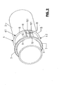
- 1 and 2 are two tubes of a piping system for a fluid under pressure, for example under high pressure, for example liquid fluid, eg for pressurized water.
- the two tubes 1 and 2 are connected via a sleeve joint 3 fluid or liquid tight and also mechanically firmly together, in particular in such a way that by the internal pressure of the pipe system or the tubes 1 and 2 no loosening of the sleeve joint 3 moving apart of the tubes 1 and 2 can be done.
- the tubes 1 and 2 are each formed at one end with a sleeve 4 and at the other end without a sleeve.
- the tube 2 is inserted with its sleeve-free end in the sleeve 4 and in the provided with the sleeve 4 end of the tube 1.
- the tube 2 enclosing ring seal 5 is arranged made of a rubber-elastic material.
- a clamping ring is fixed by clamping on the tube 2, which is received with a ring portion 7 in a socket interior 4.1 of the sleeve 4 and the sleeve 4 in the region of the sleeve opening at a radially inwardly directed Sleeve edge 4.2 engages behind.
- a further annular portion 8 of the clamping ring 6 is supported outside of the sleeve 4 and the sleeve joint 3 on the outer surface of the tube 2 from.
- a ring-shaped or semi-annular projection 9 is applied within the sleeve interior 4.1, for example in the simplest case by one or more annular or partially annular, concentric with the axis of the tube 2 extending welds against which the clamping ring 6 with the ring section 7, so that generated by the internal pressure within the tubes 1 and 2 generated axial forces between the tubes 1 and 2 via the at least one projection 9, the ring portion 7 on the annular sleeve edge 4.2 and thus a movement apart of the tubes 1 and 2 is prevented.
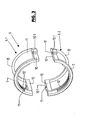
- the clamping ring 6 is made in two parts, ie it consists of two clamping ring parts 6.1 and 6.2, which are identical in the illustrated embodiment and each have the two circular arc-shaped ring sections 7 and 8, which are interconnected at both ends by a clamping ring portion or web 10 are, to a kind of circular arcuate frame-like structure.
- the webs 10 are oriented with their longitudinal extent parallel to the axis of the tubes 1 and 2, and each out of the socket interior 4.1 through the socket opening so led out.
- the respective ring portion 7 is thus within the sleeve interior 4.1 and the associated ring portion 8 outside of the sleeve interior 4.1.
- the arcuate curved ring sections 7 are provided on the convex inner side with a profiling 13, which is formed by a plurality of part-annular, concentric with the axis of the clamping ring 6 extending projections and recesses therebetween.
- the projections have, for example, a barb-like profile in such a way that an additional axial securing of the clamping ring 6 is achieved by this profile during clamping of the clamping ring 6 and the clamping ring parts 6.1 and 6.2 on the outer surface of the tube 2 by the abutting against the pipe outer surface profiling is.
- the sleeve joint 3 is for example made so that the tube 2 is inserted into the prepared with the seal 5 sleeve 4 and then the two clamping ring parts 6.1 and 6.2 are used with their ring section 7 in the socket interior 4.1 such that they engage behind the sleeve edge 4.2.
- the sleeve 4 is formed, for example in the region of the inwardly directed sleeve edge 4.2 with appropriate interruptions.
- the ring sections 7, which serve the mechanical connection of the tubes 1 and 2 are in the illustrated embodiment solid, ie designed with a larger cross-section than the ring sections 8, each only the support of Clamping ring parts 6.1 and 6.2 serve outside of the sleeve 3 and is prevented by the fact that the clamping ring parts 6.1 and 6.2 tilt during clamping of the clamping screws 12.
- the ring sections 7 and 8 and by acting between these ring sections on the webs 10 clamping screws results in a tilting of the clamping ring parts 6.1 and 6.2 preventing bilateral support of the clamping ring parts 6.1 and 6.2 on the outer surface of the tube 2.
- the webs 10 are each made reinforced in the region of the openings 11, with a wider portion 10.1, which up to the Transition to the ring section 8 is enough.
- the clamping ring parts 6.1 and 6.2 are each made in one piece from a break-resistant material, for example made of a metallic material, preferably made of steel.
Landscapes
- Engineering & Computer Science (AREA)
- General Engineering & Computer Science (AREA)
- Mechanical Engineering (AREA)
- Flanged Joints, Insulating Joints, And Other Joints (AREA)
- Mutual Connection Of Rods And Tubes (AREA)
Applications Claiming Priority (1)
| Application Number | Priority Date | Filing Date | Title |
|---|---|---|---|
| DE202009017002U DE202009017002U1 (de) | 2009-12-16 | 2009-12-16 | Muffenverbindung sowie Klemmring zur Verwendung bei einer Muffenverbindung |
Publications (2)
| Publication Number | Publication Date |
|---|---|
| EP2336624A2 true EP2336624A2 (fr) | 2011-06-22 |
| EP2336624A3 EP2336624A3 (fr) | 2013-08-07 |
Family
ID=42169163
Family Applications (1)
| Application Number | Title | Priority Date | Filing Date |
|---|---|---|---|
| EP20100015301 Withdrawn EP2336624A3 (fr) | 2009-12-16 | 2010-12-04 | Raccord de tuyaux à manchon et collier de serrage pour l'utilisation dans un raccord de tuyaux à manchon |
Country Status (2)
| Country | Link |
|---|---|
| EP (1) | EP2336624A3 (fr) |
| DE (1) | DE202009017002U1 (fr) |
Cited By (1)
| Publication number | Priority date | Publication date | Assignee | Title |
|---|---|---|---|---|
| EP3460305A1 (fr) | 2017-09-23 | 2019-03-27 | Electrosteel Castings Limited an Indian Ltd. Co | Bague de serrage de retenue permettant de raccorder deux tuyaux et des tuyaux à des raccords |
Citations (2)
| Publication number | Priority date | Publication date | Assignee | Title |
|---|---|---|---|---|
| AT372769B (de) | 1980-12-15 | 1983-11-10 | Tiroler Roehren & Metallwerk | Muffenverbindung |
| EP1055858A2 (fr) | 1999-05-18 | 2000-11-29 | Tiroler Röhren- und Metallwerke Aktiengesellschaft | Raccord de tuyaux à manchon et dispositif de serrage pour un raccord de tuyaux à manchon |
Family Cites Families (3)
| Publication number | Priority date | Publication date | Assignee | Title |
|---|---|---|---|---|
| CH669442A5 (en) * | 1986-02-27 | 1989-03-15 | Heer & Co | Compression connector for pipes - has two=part insert to clamp around male connector and with seal inside female sleeve |
| DE19918717C1 (de) * | 1999-04-24 | 2001-01-18 | Tiroler Roehren & Metallwerk | Muffenverbindung zur Verbindung zweier Rohre |
| EP1541915B1 (fr) * | 2003-12-08 | 2015-12-02 | Bayard S.A. | Dispositif de verrouillage du raccordement d'éléments de canalisation et procédé de mise en place corrspondant |
-
2009
- 2009-12-16 DE DE202009017002U patent/DE202009017002U1/de not_active Expired - Lifetime
-
2010
- 2010-12-04 EP EP20100015301 patent/EP2336624A3/fr not_active Withdrawn
Patent Citations (2)
| Publication number | Priority date | Publication date | Assignee | Title |
|---|---|---|---|---|
| AT372769B (de) | 1980-12-15 | 1983-11-10 | Tiroler Roehren & Metallwerk | Muffenverbindung |
| EP1055858A2 (fr) | 1999-05-18 | 2000-11-29 | Tiroler Röhren- und Metallwerke Aktiengesellschaft | Raccord de tuyaux à manchon et dispositif de serrage pour un raccord de tuyaux à manchon |
Cited By (1)
| Publication number | Priority date | Publication date | Assignee | Title |
|---|---|---|---|---|
| EP3460305A1 (fr) | 2017-09-23 | 2019-03-27 | Electrosteel Castings Limited an Indian Ltd. Co | Bague de serrage de retenue permettant de raccorder deux tuyaux et des tuyaux à des raccords |
Also Published As
| Publication number | Publication date |
|---|---|
| DE202009017002U1 (de) | 2010-05-12 |
| EP2336624A3 (fr) | 2013-08-07 |
Similar Documents
| Publication | Publication Date | Title |
|---|---|---|
| EP0186727B1 (fr) | Raccord de conduits | |
| EP1914465B1 (fr) | Connexion à brides pour tuyaux | |
| EP0175856B1 (fr) | Collier de serrage avec vis tendeuse | |
| EP0513292A1 (fr) | Raccord de tuyaux, notamment de tuyaux d'assemblage. | |
| EP2330326B1 (fr) | Composant tubulaire | |
| EP2492569A2 (fr) | Liaison pour manchon | |
| DE1965422A1 (de) | Elektrisch isolierendes Zwischenstueck fuer Metallrohrleitungen | |
| DE202016100359U1 (de) | Dichtringanordnung | |
| DE102021115904A1 (de) | Flanschverbindungsanordnung für eine rohrleitung | |
| EP3073166B1 (fr) | Raccord à bride | |
| DE10021184C2 (de) | Feststofftransportrohr | |
| WO2014169991A1 (fr) | Manchon de serrage | |
| DE3719585A1 (de) | Loesbare sowie nichtloesbare dichte verbindung zweier benachbarter rohrleitungen | |
| EP2336624A2 (fr) | Raccord de tuyaux à manchon et collier de serrage pour l'utilisation dans un raccord de tuyaux à manchon | |
| DE102008058042B4 (de) | Rohrkupplung für Rohre | |
| DE102008042541B4 (de) | Druckübertragungsring für Rohranordnung | |
| EP2095004B1 (fr) | Dispositif de raccordement d'appareil pour conduites de fluides | |
| DE102008017659A1 (de) | Speicherbehälter, insbesondere Pufferspeicher für Heizungen | |
| EP3341607A1 (fr) | Rampe commune de distribution à haute pression | |
| DE102023107561A1 (de) | Rohrverbinder mit Halteeinrichtung | |
| EP1317988A2 (fr) | Composant dans des pièces pour véhicule ayant un joint réalisé par soudure par pression | |
| DE10128700A1 (de) | Klemmring zum axialen Verbinden von zylindrischen Bauteilen | |
| EP0789823A1 (fr) | Systeme demontable d'assemblage et d'etancheite pour transmettre des forces de traction axiales ou des forces de pression hydraulique | |
| WO2003062694A1 (fr) | Raccord de tube a compression | |
| DE202020106261U1 (de) | Anschlussstutzen für Wellrohre |
Legal Events
| Date | Code | Title | Description |
|---|---|---|---|
| PUAI | Public reference made under article 153(3) epc to a published international application that has entered the european phase |
Free format text: ORIGINAL CODE: 0009012 |
|
| AK | Designated contracting states |
Kind code of ref document: A2 Designated state(s): AL AT BE BG CH CY CZ DE DK EE ES FI FR GB GR HR HU IE IS IT LI LT LU LV MC MK MT NL NO PL PT RO RS SE SI SK SM TR |
|
| AX | Request for extension of the european patent |
Extension state: BA ME |
|
| PUAL | Search report despatched |
Free format text: ORIGINAL CODE: 0009013 |
|
| AK | Designated contracting states |
Kind code of ref document: A3 Designated state(s): AL AT BE BG CH CY CZ DE DK EE ES FI FR GB GR HR HU IE IS IT LI LT LU LV MC MK MT NL NO PL PT RO RS SE SI SK SM TR |
|
| AX | Request for extension of the european patent |
Extension state: BA ME |
|
| RIC1 | Information provided on ipc code assigned before grant |
Ipc: F16L 21/08 20060101AFI20130628BHEP |
|
| 17P | Request for examination filed |
Effective date: 20140206 |
|
| RBV | Designated contracting states (corrected) |
Designated state(s): AL AT BE BG CH CY CZ DE DK EE ES FI FR GB GR HR HU IE IS IT LI LT LU LV MC MK MT NL NO PL PT RO RS SE SI SK SM TR |
|
| 17Q | First examination report despatched |
Effective date: 20150504 |
|
| GRAP | Despatch of communication of intention to grant a patent |
Free format text: ORIGINAL CODE: EPIDOSNIGR1 |
|
| INTG | Intention to grant announced |
Effective date: 20160118 |
|
| STAA | Information on the status of an ep patent application or granted ep patent |
Free format text: STATUS: THE APPLICATION IS DEEMED TO BE WITHDRAWN |
|
| 18D | Application deemed to be withdrawn |
Effective date: 20160531 |