EP3460305A1 - Bague de serrage de retenue permettant de raccorder deux tuyaux et des tuyaux à des raccords - Google Patents
Bague de serrage de retenue permettant de raccorder deux tuyaux et des tuyaux à des raccords Download PDFInfo
- Publication number
- EP3460305A1 EP3460305A1 EP17202505.8A EP17202505A EP3460305A1 EP 3460305 A1 EP3460305 A1 EP 3460305A1 EP 17202505 A EP17202505 A EP 17202505A EP 3460305 A1 EP3460305 A1 EP 3460305A1
- Authority
- EP
- European Patent Office
- Prior art keywords
- pipe
- clamp ring
- clamping
- restraining clamp
- socket
- Prior art date
- Legal status (The legal status is an assumption and is not a legal conclusion. Google has not performed a legal analysis and makes no representation as to the accuracy of the status listed.)
- Granted
Links
- 230000000452 restraining effect Effects 0.000 title claims abstract description 25
- 229910001141 Ductile iron Inorganic materials 0.000 claims description 2
- 239000011324 bead Substances 0.000 description 4
- 238000003780 insertion Methods 0.000 description 4
- 230000037431 insertion Effects 0.000 description 4
- 230000007246 mechanism Effects 0.000 description 4
- 230000008878 coupling Effects 0.000 description 3
- 238000010168 coupling process Methods 0.000 description 3
- 238000005859 coupling reaction Methods 0.000 description 3
- 238000009434 installation Methods 0.000 description 3
- 238000012986 modification Methods 0.000 description 3
- 230000004048 modification Effects 0.000 description 3
- 238000000926 separation method Methods 0.000 description 3
- 230000004075 alteration Effects 0.000 description 2
- 230000009471 action Effects 0.000 description 1
- 230000013011 mating Effects 0.000 description 1
- 238000007789 sealing Methods 0.000 description 1
Images

Classifications
-
- F—MECHANICAL ENGINEERING; LIGHTING; HEATING; WEAPONS; BLASTING
- F16—ENGINEERING ELEMENTS AND UNITS; GENERAL MEASURES FOR PRODUCING AND MAINTAINING EFFECTIVE FUNCTIONING OF MACHINES OR INSTALLATIONS; THERMAL INSULATION IN GENERAL
- F16L—PIPES; JOINTS OR FITTINGS FOR PIPES; SUPPORTS FOR PIPES, CABLES OR PROTECTIVE TUBING; MEANS FOR THERMAL INSULATION IN GENERAL
- F16L21/00—Joints with sleeve or socket
- F16L21/08—Joints with sleeve or socket with additional locking means
Definitions
- the present invention relates to a pipe joint assembly adapted including a clamp device for use in pipe fittings. More particularly, the present invention relates to a Restraining Clamp Ring for jointing two pipes and pipes to fittings to avoid axial separation of pipes or fittings, during pressurization of the pipe line.
- One well known form of pipe joint for example, comprises a bell end provided on one pipe, an inter-fitting spigot end on an attached pipe, and a sealing gasket interposed between the bell and spigot ends.
- Numerous locking arrangements have been proposed for use in such joints to prevent axial movement of the spigot end relative to the bell end.
- one such locking arrangement employs a split ring located inside of the bell end and which can be adjusted radially by a ring adjustment mechanism between a relaxed condition allowing for axial movement of the respective pipe ends and a tightened position in which the ring engages a circumferential bead or the like on one of the pipe ends to preclude relative axial movement there between in a direction separating the pipes.
- the adjustment mechanism for the snap ring comprises transverse pieces which extend axially from the respective ends of the split snap ring out of the mouth of the bell end, radial lugs on the outer ends of the transverse pieces, and a threaded stud connecting the lugs whereby radial adjustment of the segmented ring within the bell end as between the relaxed and tightened conditions is effected externally of the bell end by rotating the threaded stud nuts in the appropriate direction.
- a French application FR2376985 (A1 ) discloses a socket or sleeve pipe coupling having an outer clamp ring with internal cones to successively deform outer coupling member.
- the pipe coupling is affected by clamp rings with conical inner surface being secured over the socket end or the outer sleeve. This produces a sealed joint between the pipe and sleeve by inward deformation.
- Each clamp ring has a first conical inner portion followed by a cylindrical portion and a second conical portion.
- the diameter of the cylindrical portion is equals to the small diameter of the first and the large diameter of the second conical portion.
- the outer diameter of the sleeve before fixing the ring approximately equals the large diameter of the first portion.
- a European application EP2336624 (A2 ) discloses a clamp ring for use in a socket joint.
- the disclosed fitting has a socket for forming an inward projecting socket edge at a socket opening, and a clamping ring with ring segment shape clamping ring parts.
- Ring sections of the socket engage in a socket inner chamber in a form-fit manner.
- the ring sections are pre-stressed with each other at a pipe at clamping ring bars by clamping elements.
- the clamping ring parts at a side of the clamping elements are formed with support elements, where the side is turned away from the socket.
- the support elements are supported at an external surface of the pipe.
- a European application EP2940362 (A1 ) discloses a spigot-and-socket pipe joint.
- a stopper ring of the joint has a split structure comprising a plurality of stoppers.
- Two or more fixing holes are provided in the face of the outer diameter of each stopper for installing an elastic support.
- the stoppers are first installed in a stopper chamber one by one to form a whole and finally a spigot is installed into a socket.
- a spigot projection can push the stopper to move backwards and compress the elastic support on the stopper ring when passing through the stopper ring, and the spigot projection would pull the spigot back after passing through the stopper ring, so that the stopper presses against the outer surface of the spigot by the elastic support.
- the spigot-and-socket pipe joint in the invention has simple structure, convenience in installation and disassembly, strong anti-slip capability and wide application.
- a restraining clamp ring (1) adapted for use with pipe joint assembly and / or pipe fittings wherein the pipe joint assembly includes overlapping of a socket end (7) of one pipe and a taper end (8) of another pipe, wherein the socket has a cavity (7A) with at least two openings (7B); and wherein the taper (8) end of the pipe is held inside the socket by a "V" shaped recess (2A) having two ring type clamping halves (1A), each having two lever arms (1C) extending along the length of the pipe.
- the said restrained joint is achieved by a restraining clamp ring assembly including two ring type clamping halves each having two lever arms extending along the length of the pipe.
- the piping system includes a socket end of one pipe wherein the taper end of another pipe is inserted.
- the said socket has a cavity with at least two openings and the said clamping assembly is configured for holding the taper end inside the socket by a "V" shaped recess.
- the clamping halves possess two rotating members when position in proper place and bolts of the lever arms are tightened ensures that movement of the free ends of the arms are restricted and entire movements is transmitted to the rings ensuring proper biting of the teeth on the spigot.
- position pins configured for restricting the movement of arms and the said movement are transmitted to the open side of the arms as there is a presence of resisting force and transmit the tightening torque to biting force at recesses.
- the said position pins ensure proper alignment of the halves and do not allow any axial movement of the halves, irrespective of dimensional tolerances of the mating parts, proper biting of V shaped recess in the spigot metallic wall.
- the said clamping halves (1) are inserted in to the socket end restraining chamber and retracted to the inner periphery of socket restraining chamber to create maximum internal diameter to allow insertion of spigot end easily through it.
- the spigot end of pipe is then pushed in to the socket, up to the required insertion length.
- Such a configuration of the clamping assembly has been found to be particularly advantageous, in particular from the point of view of the clamping action and the handling.
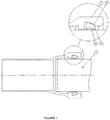
- the present invention relates to a Restraining Clamp Ring for jointing two pipes and pipes to fittings to avoid axial separation of pipes or fittings, during pressurization of the pipe line in particular reference to Fig. 1 .
- Several restraining mechanisms to avoid axial separation of pipes or fittings, during pressurization, are available. Most of these mechanisms require factory applied weld bead at the end (spigot end) of pipes. Making weld bead at site condition is very difficult, as it requires special equipments, consumables and expertise. This invention will work without any weld bead for restrained flexible joint.
- Clamp ring is designed in two halves (1).
- Each half (1) has a radially inward metallic projecting edge (2) with at least two sharp "V" shaped recesses (2A).
- Both ends of each half (1) have an extended lever arm (1B) along pipe's longitudinal axis.
- Lever arm (1B) has a hole (1C), parallel to pipe's horizontal diametral axis, to pass a clamping bolt (5) through it.
- End of lever arm (1B) has a rectangular slot (1D), parallel to pipe's horizontal diametral axis, to allow a pin (3) through it. External diameter of this pin (3B), at the middle of its length, is bigger than the length of the slots (W).
- One end of the pin (3A) is hinged at one of the lever slots (1D), in such a way, so that other end (3A)is free to rotate and can be rest on the slot (1D) of other lever arm (1B).
- This pin (3) thus rested at both the slots (1D), favors proper alignment of clamping halves (1), with respect to pipe axis, during tightening of clamping bolts (5) and act as a lever fulcrum (4) to transmit tightening torque to biting force at V shaped recess (2A) on the pipe's (8) external periphery.
- the two clamping halves (1) are initially connected, loosely, to each other, by means of two clamping bolts (5), passing through the holes (1C) provided at the end of lever arms (1B). Clamping halves (1) are loosely connected so that internal diameter comprises by these two halves (1), can be varied. Clamping halves (1), so connected, are inserted in to the socket (7) restraining chamber and retracted to the inner periphery (7A) of socket restraining chamber to create maximum internal diameter to allow insertion of spigot (8) end easily through it. Spigot end (8) of pipe is then pushed in to the socket (7), up to the required insertion length. Then the clamping bolts (5) are tightened.
- the said clamping rings (1) are preferably made with ductile Iron (420/5).
- the tip of the recess (2A) is especially hardened to 510 BHN to ensure easy biting into the spigot end.
Landscapes
- Engineering & Computer Science (AREA)
- General Engineering & Computer Science (AREA)
- Mechanical Engineering (AREA)
- Clamps And Clips (AREA)
- Flanged Joints, Insulating Joints, And Other Joints (AREA)
Applications Claiming Priority (1)
| Application Number | Priority Date | Filing Date | Title |
|---|---|---|---|
| IN201731033786 | 2017-09-23 |
Publications (2)
| Publication Number | Publication Date |
|---|---|
| EP3460305A1 true EP3460305A1 (fr) | 2019-03-27 |
| EP3460305B1 EP3460305B1 (fr) | 2020-10-14 |
Family
ID=60409209
Family Applications (1)
| Application Number | Title | Priority Date | Filing Date |
|---|---|---|---|
| EP17202505.8A Active EP3460305B1 (fr) | 2017-09-23 | 2017-11-20 | Bague de serrage de retenue permettant de raccorder deux tuyaux et des tuyaux à des raccords |
Country Status (2)
| Country | Link |
|---|---|
| EP (1) | EP3460305B1 (fr) |
| ES (1) | ES2841529T3 (fr) |
Cited By (5)
| Publication number | Priority date | Publication date | Assignee | Title |
|---|---|---|---|---|
| CN110823677A (zh) * | 2019-11-19 | 2020-02-21 | 中国飞机强度研究所 | 一种用于拉压垫杠杆加载系统的杠杆接头 |
| CN113483149A (zh) * | 2021-06-25 | 2021-10-08 | 中国一冶集团有限公司 | 一种承插式pccp管对接装置 |
| CN114776885A (zh) * | 2022-04-11 | 2022-07-22 | 新兴铸管股份有限公司 | 内顶推球墨铸铁顶管及其装配方法与装配工具 |
| FR3119876A1 (fr) | 2021-02-17 | 2022-08-19 | Electrosteel Europe Sa | Ensemble de verrouillage pret-a-monter pour jonction tubulaire flexible entre deux elements de canalisation |
| CN120572268A (zh) * | 2025-08-04 | 2025-09-02 | 四川川化鑫和检测技术有限公司 | 一种石油化工管道工程用自动焊接设备及焊接方法 |
Citations (5)
| Publication number | Priority date | Publication date | Assignee | Title |
|---|---|---|---|---|
| FR2376985A1 (fr) | 1977-01-06 | 1978-08-04 | Moebius Kurt | Joint d'assemblage de tubes a bague de blocage |
| EP1055858A2 (fr) * | 1999-05-18 | 2000-11-29 | Tiroler Röhren- und Metallwerke Aktiengesellschaft | Raccord de tuyaux à manchon et dispositif de serrage pour un raccord de tuyaux à manchon |
| EP2336624A2 (fr) | 2009-12-16 | 2011-06-22 | STR Rohr GmbH | Raccord de tuyaux à manchon et collier de serrage pour l'utilisation dans un raccord de tuyaux à manchon |
| DE202013103431U1 (de) * | 2013-07-31 | 2014-11-04 | Tiroler Rohre GmbH | Klemmring |
| EP2940362A1 (fr) | 2013-11-14 | 2015-11-04 | Xinxing Ductile Iron Pipes Co., Ltd | Joint de tuyau à emboîtement, ses procédés de montage et de démontage, pince de montage et outil de démontage |
-
2017
- 2017-11-20 EP EP17202505.8A patent/EP3460305B1/fr active Active
- 2017-11-20 ES ES17202505T patent/ES2841529T3/es active Active
Patent Citations (5)
| Publication number | Priority date | Publication date | Assignee | Title |
|---|---|---|---|---|
| FR2376985A1 (fr) | 1977-01-06 | 1978-08-04 | Moebius Kurt | Joint d'assemblage de tubes a bague de blocage |
| EP1055858A2 (fr) * | 1999-05-18 | 2000-11-29 | Tiroler Röhren- und Metallwerke Aktiengesellschaft | Raccord de tuyaux à manchon et dispositif de serrage pour un raccord de tuyaux à manchon |
| EP2336624A2 (fr) | 2009-12-16 | 2011-06-22 | STR Rohr GmbH | Raccord de tuyaux à manchon et collier de serrage pour l'utilisation dans un raccord de tuyaux à manchon |
| DE202013103431U1 (de) * | 2013-07-31 | 2014-11-04 | Tiroler Rohre GmbH | Klemmring |
| EP2940362A1 (fr) | 2013-11-14 | 2015-11-04 | Xinxing Ductile Iron Pipes Co., Ltd | Joint de tuyau à emboîtement, ses procédés de montage et de démontage, pince de montage et outil de démontage |
Cited By (7)
| Publication number | Priority date | Publication date | Assignee | Title |
|---|---|---|---|---|
| CN110823677A (zh) * | 2019-11-19 | 2020-02-21 | 中国飞机强度研究所 | 一种用于拉压垫杠杆加载系统的杠杆接头 |
| FR3119876A1 (fr) | 2021-02-17 | 2022-08-19 | Electrosteel Europe Sa | Ensemble de verrouillage pret-a-monter pour jonction tubulaire flexible entre deux elements de canalisation |
| WO2022175127A1 (fr) | 2021-02-17 | 2022-08-25 | Electrosteel Europe Sa | Ensemble de verrouillage pret-a-monter pour jonction tubulaire flexible entre deux elements de canalisation |
| CN113483149A (zh) * | 2021-06-25 | 2021-10-08 | 中国一冶集团有限公司 | 一种承插式pccp管对接装置 |
| CN113483149B (zh) * | 2021-06-25 | 2023-05-16 | 中国一冶集团有限公司 | 一种承插式pccp管对接装置 |
| CN114776885A (zh) * | 2022-04-11 | 2022-07-22 | 新兴铸管股份有限公司 | 内顶推球墨铸铁顶管及其装配方法与装配工具 |
| CN120572268A (zh) * | 2025-08-04 | 2025-09-02 | 四川川化鑫和检测技术有限公司 | 一种石油化工管道工程用自动焊接设备及焊接方法 |
Also Published As
| Publication number | Publication date |
|---|---|
| EP3460305B1 (fr) | 2020-10-14 |
| ES2841529T3 (es) | 2021-07-08 |
Similar Documents
| Publication | Publication Date | Title |
|---|---|---|
| EP3460305B1 (fr) | Bague de serrage de retenue permettant de raccorder deux tuyaux et des tuyaux à des raccords | |
| US12486929B2 (en) | Adapter coupling | |
| US9441771B2 (en) | Pipe coupling device | |
| EP2463567B1 (fr) | Ensemble formant collier de serrage doté d'une bague de l'élément de serrage | |
| US3685860A (en) | Hose coupling | |
| EP2932145B1 (fr) | Pont jointé pour ensemble de serrage | |
| US20110084484A1 (en) | Self-restrained pipe joint system and method of assembly | |
| JP2019509449A (ja) | タブ付きリテーナを有するカップリング | |
| CN106415104A (zh) | 凸缘接合部加固夹具 | |
| US7552949B2 (en) | Joint restraint for pipe fittings | |
| JP5269178B2 (ja) | 管継手の組立て方法 | |
| JP4939826B2 (ja) | 管継手の組立て方法 | |
| US7731240B2 (en) | Pipe coupling | |
| JP6860913B2 (ja) | 離脱防止管継手、及び、管継手の離脱防止方法 | |
| JPH10122456A (ja) | 管継手の耐震構造 | |
| EP3732387B1 (fr) | Raccord de tuyaux de retenue | |
| JP7253389B2 (ja) | 継手部材 | |
| EP3623678B1 (fr) | Système de support de serrage | |
| JP2003269666A (ja) | 管の継手構造 | |
| NZ742362B (en) | Adapter coupling | |
| JPH05506080A (ja) | ホースを接続具に取り付ける装置 | |
| GB2563676A (en) | Gripping collar and corresponding tubular joint | |
| HK1230696A1 (en) | Flange coupling part reinforcing jig | |
| KR19990026808A (ko) | 파이프 커플링 및 파이프 고정방법 | |
| JP2012197869A (ja) | 管継手 |
Legal Events
| Date | Code | Title | Description |
|---|---|---|---|
| PUAI | Public reference made under article 153(3) epc to a published international application that has entered the european phase |
Free format text: ORIGINAL CODE: 0009012 |
|
| STAA | Information on the status of an ep patent application or granted ep patent |
Free format text: STATUS: THE APPLICATION HAS BEEN PUBLISHED |
|
| AK | Designated contracting states |
Kind code of ref document: A1 Designated state(s): AL AT BE BG CH CY CZ DE DK EE ES FI FR GB GR HR HU IE IS IT LI LT LU LV MC MK MT NL NO PL PT RO RS SE SI SK SM TR |
|
| AX | Request for extension of the european patent |
Extension state: BA ME |
|
| STAA | Information on the status of an ep patent application or granted ep patent |
Free format text: STATUS: REQUEST FOR EXAMINATION WAS MADE |
|
| 17P | Request for examination filed |
Effective date: 20190821 |
|
| RBV | Designated contracting states (corrected) |
Designated state(s): AL AT BE BG CH CY CZ DE DK EE ES FI FR GB GR HR HU IE IS IT LI LT LU LV MC MK MT NL NO PL PT RO RS SE SI SK SM TR |
|
| GRAP | Despatch of communication of intention to grant a patent |
Free format text: ORIGINAL CODE: EPIDOSNIGR1 |
|
| STAA | Information on the status of an ep patent application or granted ep patent |
Free format text: STATUS: GRANT OF PATENT IS INTENDED |
|
| RIC1 | Information provided on ipc code assigned before grant |
Ipc: F16L 21/08 20060101AFI20200416BHEP |
|
| INTG | Intention to grant announced |
Effective date: 20200514 |
|
| RAP1 | Party data changed (applicant data changed or rights of an application transferred) |
Owner name: ELECTROSTEEL CASTINGS LIMITED |
|
| GRAS | Grant fee paid |
Free format text: ORIGINAL CODE: EPIDOSNIGR3 |
|
| GRAA | (expected) grant |
Free format text: ORIGINAL CODE: 0009210 |
|
| STAA | Information on the status of an ep patent application or granted ep patent |
Free format text: STATUS: THE PATENT HAS BEEN GRANTED |
|
| AK | Designated contracting states |
Kind code of ref document: B1 Designated state(s): AL AT BE BG CH CY CZ DE DK EE ES FI FR GB GR HR HU IE IS IT LI LT LU LV MC MK MT NL NO PL PT RO RS SE SI SK SM TR |
|
| REG | Reference to a national code |
Ref country code: GB Ref legal event code: FG4D |
|
| REG | Reference to a national code |
Ref country code: AT Ref legal event code: REF Ref document number: 1323921 Country of ref document: AT Kind code of ref document: T Effective date: 20201015 Ref country code: CH Ref legal event code: EP |
|
| REG | Reference to a national code |
Ref country code: DE Ref legal event code: R096 Ref document number: 602017025338 Country of ref document: DE |
|
| REG | Reference to a national code |
Ref country code: IE Ref legal event code: FG4D |
|
| REG | Reference to a national code |
Ref country code: NL Ref legal event code: MP Effective date: 20201014 |
|
| PG25 | Lapsed in a contracting state [announced via postgrant information from national office to epo] |
Ref country code: NO Free format text: LAPSE BECAUSE OF FAILURE TO SUBMIT A TRANSLATION OF THE DESCRIPTION OR TO PAY THE FEE WITHIN THE PRESCRIBED TIME-LIMIT Effective date: 20210114 Ref country code: RS Free format text: LAPSE BECAUSE OF FAILURE TO SUBMIT A TRANSLATION OF THE DESCRIPTION OR TO PAY THE FEE WITHIN THE PRESCRIBED TIME-LIMIT Effective date: 20201014 Ref country code: PT Free format text: LAPSE BECAUSE OF FAILURE TO SUBMIT A TRANSLATION OF THE DESCRIPTION OR TO PAY THE FEE WITHIN THE PRESCRIBED TIME-LIMIT Effective date: 20210215 Ref country code: FI Free format text: LAPSE BECAUSE OF FAILURE TO SUBMIT A TRANSLATION OF THE DESCRIPTION OR TO PAY THE FEE WITHIN THE PRESCRIBED TIME-LIMIT Effective date: 20201014 Ref country code: GR Free format text: LAPSE BECAUSE OF FAILURE TO SUBMIT A TRANSLATION OF THE DESCRIPTION OR TO PAY THE FEE WITHIN THE PRESCRIBED TIME-LIMIT Effective date: 20210115 |
|
| REG | Reference to a national code |
Ref country code: LT Ref legal event code: MG4D |
|
| PG25 | Lapsed in a contracting state [announced via postgrant information from national office to epo] |
Ref country code: SE Free format text: LAPSE BECAUSE OF FAILURE TO SUBMIT A TRANSLATION OF THE DESCRIPTION OR TO PAY THE FEE WITHIN THE PRESCRIBED TIME-LIMIT Effective date: 20201014 Ref country code: IS Free format text: LAPSE BECAUSE OF FAILURE TO SUBMIT A TRANSLATION OF THE DESCRIPTION OR TO PAY THE FEE WITHIN THE PRESCRIBED TIME-LIMIT Effective date: 20210214 Ref country code: PL Free format text: LAPSE BECAUSE OF FAILURE TO SUBMIT A TRANSLATION OF THE DESCRIPTION OR TO PAY THE FEE WITHIN THE PRESCRIBED TIME-LIMIT Effective date: 20201014 Ref country code: LV Free format text: LAPSE BECAUSE OF FAILURE TO SUBMIT A TRANSLATION OF THE DESCRIPTION OR TO PAY THE FEE WITHIN THE PRESCRIBED TIME-LIMIT Effective date: 20201014 Ref country code: BG Free format text: LAPSE BECAUSE OF FAILURE TO SUBMIT A TRANSLATION OF THE DESCRIPTION OR TO PAY THE FEE WITHIN THE PRESCRIBED TIME-LIMIT Effective date: 20210114 |
|
| PG25 | Lapsed in a contracting state [announced via postgrant information from national office to epo] |
Ref country code: NL Free format text: LAPSE BECAUSE OF FAILURE TO SUBMIT A TRANSLATION OF THE DESCRIPTION OR TO PAY THE FEE WITHIN THE PRESCRIBED TIME-LIMIT Effective date: 20201014 Ref country code: HR Free format text: LAPSE BECAUSE OF FAILURE TO SUBMIT A TRANSLATION OF THE DESCRIPTION OR TO PAY THE FEE WITHIN THE PRESCRIBED TIME-LIMIT Effective date: 20201014 |
|
| REG | Reference to a national code |
Ref country code: CH Ref legal event code: PL |
|
| REG | Reference to a national code |
Ref country code: ES Ref legal event code: FG2A Ref document number: 2841529 Country of ref document: ES Kind code of ref document: T3 Effective date: 20210708 |
|
| REG | Reference to a national code |
Ref country code: DE Ref legal event code: R097 Ref document number: 602017025338 Country of ref document: DE |
|
| PG25 | Lapsed in a contracting state [announced via postgrant information from national office to epo] |
Ref country code: SM Free format text: LAPSE BECAUSE OF FAILURE TO SUBMIT A TRANSLATION OF THE DESCRIPTION OR TO PAY THE FEE WITHIN THE PRESCRIBED TIME-LIMIT Effective date: 20201014 Ref country code: LT Free format text: LAPSE BECAUSE OF FAILURE TO SUBMIT A TRANSLATION OF THE DESCRIPTION OR TO PAY THE FEE WITHIN THE PRESCRIBED TIME-LIMIT Effective date: 20201014 Ref country code: LU Free format text: LAPSE BECAUSE OF NON-PAYMENT OF DUE FEES Effective date: 20201120 Ref country code: MC Free format text: LAPSE BECAUSE OF FAILURE TO SUBMIT A TRANSLATION OF THE DESCRIPTION OR TO PAY THE FEE WITHIN THE PRESCRIBED TIME-LIMIT Effective date: 20201014 Ref country code: CZ Free format text: LAPSE BECAUSE OF FAILURE TO SUBMIT A TRANSLATION OF THE DESCRIPTION OR TO PAY THE FEE WITHIN THE PRESCRIBED TIME-LIMIT Effective date: 20201014 Ref country code: EE Free format text: LAPSE BECAUSE OF FAILURE TO SUBMIT A TRANSLATION OF THE DESCRIPTION OR TO PAY THE FEE WITHIN THE PRESCRIBED TIME-LIMIT Effective date: 20201014 Ref country code: SK Free format text: LAPSE BECAUSE OF FAILURE TO SUBMIT A TRANSLATION OF THE DESCRIPTION OR TO PAY THE FEE WITHIN THE PRESCRIBED TIME-LIMIT Effective date: 20201014 Ref country code: RO Free format text: LAPSE BECAUSE OF FAILURE TO SUBMIT A TRANSLATION OF THE DESCRIPTION OR TO PAY THE FEE WITHIN THE PRESCRIBED TIME-LIMIT Effective date: 20201014 |
|
| PLBE | No opposition filed within time limit |
Free format text: ORIGINAL CODE: 0009261 |
|
| STAA | Information on the status of an ep patent application or granted ep patent |
Free format text: STATUS: NO OPPOSITION FILED WITHIN TIME LIMIT |
|
| PG25 | Lapsed in a contracting state [announced via postgrant information from national office to epo] |
Ref country code: CH Free format text: LAPSE BECAUSE OF NON-PAYMENT OF DUE FEES Effective date: 20201130 Ref country code: LI Free format text: LAPSE BECAUSE OF NON-PAYMENT OF DUE FEES Effective date: 20201130 Ref country code: DK Free format text: LAPSE BECAUSE OF FAILURE TO SUBMIT A TRANSLATION OF THE DESCRIPTION OR TO PAY THE FEE WITHIN THE PRESCRIBED TIME-LIMIT Effective date: 20201014 |
|
| 26N | No opposition filed |
Effective date: 20210715 |
|
| PG25 | Lapsed in a contracting state [announced via postgrant information from national office to epo] |
Ref country code: IE Free format text: LAPSE BECAUSE OF NON-PAYMENT OF DUE FEES Effective date: 20201120 Ref country code: AL Free format text: LAPSE BECAUSE OF FAILURE TO SUBMIT A TRANSLATION OF THE DESCRIPTION OR TO PAY THE FEE WITHIN THE PRESCRIBED TIME-LIMIT Effective date: 20201014 |
|
| PG25 | Lapsed in a contracting state [announced via postgrant information from national office to epo] |
Ref country code: SI Free format text: LAPSE BECAUSE OF FAILURE TO SUBMIT A TRANSLATION OF THE DESCRIPTION OR TO PAY THE FEE WITHIN THE PRESCRIBED TIME-LIMIT Effective date: 20201014 |
|
| PGFP | Annual fee paid to national office [announced via postgrant information from national office to epo] |
Ref country code: GB Payment date: 20211207 Year of fee payment: 5 Ref country code: FR Payment date: 20211130 Year of fee payment: 5 Ref country code: ES Payment date: 20211202 Year of fee payment: 5 Ref country code: DE Payment date: 20211222 Year of fee payment: 5 |
|
| PGFP | Annual fee paid to national office [announced via postgrant information from national office to epo] |
Ref country code: IT Payment date: 20211222 Year of fee payment: 5 Ref country code: BE Payment date: 20211209 Year of fee payment: 5 |
|
| PG25 | Lapsed in a contracting state [announced via postgrant information from national office to epo] |
Ref country code: IS Free format text: LAPSE BECAUSE OF FAILURE TO SUBMIT A TRANSLATION OF THE DESCRIPTION OR TO PAY THE FEE WITHIN THE PRESCRIBED TIME-LIMIT Effective date: 20210214 Ref country code: TR Free format text: LAPSE BECAUSE OF FAILURE TO SUBMIT A TRANSLATION OF THE DESCRIPTION OR TO PAY THE FEE WITHIN THE PRESCRIBED TIME-LIMIT Effective date: 20201014 Ref country code: MT Free format text: LAPSE BECAUSE OF FAILURE TO SUBMIT A TRANSLATION OF THE DESCRIPTION OR TO PAY THE FEE WITHIN THE PRESCRIBED TIME-LIMIT Effective date: 20201014 Ref country code: CY Free format text: LAPSE BECAUSE OF FAILURE TO SUBMIT A TRANSLATION OF THE DESCRIPTION OR TO PAY THE FEE WITHIN THE PRESCRIBED TIME-LIMIT Effective date: 20201014 |
|
| PG25 | Lapsed in a contracting state [announced via postgrant information from national office to epo] |
Ref country code: MK Free format text: LAPSE BECAUSE OF FAILURE TO SUBMIT A TRANSLATION OF THE DESCRIPTION OR TO PAY THE FEE WITHIN THE PRESCRIBED TIME-LIMIT Effective date: 20201014 |
|
| REG | Reference to a national code |
Ref country code: DE Ref legal event code: R119 Ref document number: 602017025338 Country of ref document: DE |
|
| GBPC | Gb: european patent ceased through non-payment of renewal fee |
Effective date: 20221120 |
|
| REG | Reference to a national code |
Ref country code: BE Ref legal event code: MM Effective date: 20221130 |
|
| PG25 | Lapsed in a contracting state [announced via postgrant information from national office to epo] |
Ref country code: IT Free format text: LAPSE BECAUSE OF NON-PAYMENT OF DUE FEES Effective date: 20221120 Ref country code: GB Free format text: LAPSE BECAUSE OF NON-PAYMENT OF DUE FEES Effective date: 20221120 Ref country code: DE Free format text: LAPSE BECAUSE OF NON-PAYMENT OF DUE FEES Effective date: 20230601 |
|
| PG25 | Lapsed in a contracting state [announced via postgrant information from national office to epo] |
Ref country code: FR Free format text: LAPSE BECAUSE OF NON-PAYMENT OF DUE FEES Effective date: 20221130 Ref country code: BE Free format text: LAPSE BECAUSE OF NON-PAYMENT OF DUE FEES Effective date: 20221130 |
|
| REG | Reference to a national code |
Ref country code: ES Ref legal event code: FD2A Effective date: 20231229 |
|
| REG | Reference to a national code |
Ref country code: AT Ref legal event code: MM01 Ref document number: 1323921 Country of ref document: AT Kind code of ref document: T Effective date: 20221120 |
|
| PG25 | Lapsed in a contracting state [announced via postgrant information from national office to epo] |
Ref country code: ES Free format text: LAPSE BECAUSE OF NON-PAYMENT OF DUE FEES Effective date: 20221121 |
|
| PG25 | Lapsed in a contracting state [announced via postgrant information from national office to epo] |
Ref country code: ES Free format text: LAPSE BECAUSE OF NON-PAYMENT OF DUE FEES Effective date: 20221121 Ref country code: AT Free format text: LAPSE BECAUSE OF NON-PAYMENT OF DUE FEES Effective date: 20221120 |
|
| REG | Reference to a national code |
Ref country code: AT Ref legal event code: UEP Ref document number: 1323921 Country of ref document: AT Kind code of ref document: T Effective date: 20201014 |