EP2337130A1 - Formteil - Google Patents
Formteil Download PDFInfo
- Publication number
- EP2337130A1 EP2337130A1 EP10015585A EP10015585A EP2337130A1 EP 2337130 A1 EP2337130 A1 EP 2337130A1 EP 10015585 A EP10015585 A EP 10015585A EP 10015585 A EP10015585 A EP 10015585A EP 2337130 A1 EP2337130 A1 EP 2337130A1
- Authority
- EP
- European Patent Office
- Prior art keywords
- starting material
- shaped
- radius
- range
- sintering
- Prior art date
- Legal status (The legal status is an assumption and is not a legal conclusion. Google has not performed a legal analysis and makes no representation as to the accuracy of the status listed.)
- Granted
Links
Images
Classifications
-
- B—PERFORMING OPERATIONS; TRANSPORTING
- B22—CASTING; POWDER METALLURGY
- B22F—WORKING METALLIC POWDER; MANUFACTURE OF ARTICLES FROM METALLIC POWDER; MAKING METALLIC POWDER; APPARATUS OR DEVICES SPECIALLY ADAPTED FOR METALLIC POWDER
- B22F3/00—Manufacture of workpieces or articles from metallic powder characterised by the manner of compacting or sintering; Apparatus specially adapted therefor ; Presses and furnaces
- B22F3/02—Compacting only
-
- B—PERFORMING OPERATIONS; TRANSPORTING
- B22—CASTING; POWDER METALLURGY
- B22F—WORKING METALLIC POWDER; MANUFACTURE OF ARTICLES FROM METALLIC POWDER; MAKING METALLIC POWDER; APPARATUS OR DEVICES SPECIALLY ADAPTED FOR METALLIC POWDER
- B22F3/00—Manufacture of workpieces or articles from metallic powder characterised by the manner of compacting or sintering; Apparatus specially adapted therefor ; Presses and furnaces
- B22F3/12—Both compacting and sintering
-
- B—PERFORMING OPERATIONS; TRANSPORTING
- B22—CASTING; POWDER METALLURGY
- B22F—WORKING METALLIC POWDER; MANUFACTURE OF ARTICLES FROM METALLIC POWDER; MAKING METALLIC POWDER; APPARATUS OR DEVICES SPECIALLY ADAPTED FOR METALLIC POWDER
- B22F5/00—Manufacture of workpieces or articles from metallic powder characterised by the special shape of the product
-
- B—PERFORMING OPERATIONS; TRANSPORTING
- B22—CASTING; POWDER METALLURGY
- B22F—WORKING METALLIC POWDER; MANUFACTURE OF ARTICLES FROM METALLIC POWDER; MAKING METALLIC POWDER; APPARATUS OR DEVICES SPECIALLY ADAPTED FOR METALLIC POWDER
- B22F5/00—Manufacture of workpieces or articles from metallic powder characterised by the special shape of the product
- B22F5/06—Manufacture of workpieces or articles from metallic powder characterised by the special shape of the product of threaded articles, e.g. nuts
-
- B—PERFORMING OPERATIONS; TRANSPORTING
- B22—CASTING; POWDER METALLURGY
- B22F—WORKING METALLIC POWDER; MANUFACTURE OF ARTICLES FROM METALLIC POWDER; MAKING METALLIC POWDER; APPARATUS OR DEVICES SPECIALLY ADAPTED FOR METALLIC POWDER
- B22F5/00—Manufacture of workpieces or articles from metallic powder characterised by the special shape of the product
- B22F5/08—Manufacture of workpieces or articles from metallic powder characterised by the special shape of the product of toothed articles, e.g. gear wheels; of cam discs
-
- C—CHEMISTRY; METALLURGY
- C22—METALLURGY; FERROUS OR NON-FERROUS ALLOYS; TREATMENT OF ALLOYS OR NON-FERROUS METALS
- C22C—ALLOYS
- C22C27/00—Alloys based on rhenium or a refractory metal not mentioned in groups C22C14/00 or C22C16/00
- C22C27/06—Alloys based on chromium
-
- C—CHEMISTRY; METALLURGY
- C22—METALLURGY; FERROUS OR NON-FERROUS ALLOYS; TREATMENT OF ALLOYS OR NON-FERROUS METALS
- C22C—ALLOYS
- C22C33/00—Making ferrous alloys
- C22C33/02—Making ferrous alloys by powder metallurgy
- C22C33/0207—Using a mixture of pre-alloyed powders or a master alloy
-
- C—CHEMISTRY; METALLURGY
- C22—METALLURGY; FERROUS OR NON-FERROUS ALLOYS; TREATMENT OF ALLOYS OR NON-FERROUS METALS
- C22C—ALLOYS
- C22C33/00—Making ferrous alloys
- C22C33/02—Making ferrous alloys by powder metallurgy
- C22C33/0257—Making ferrous alloys by powder metallurgy characterised by the range of the alloying elements
- C22C33/0278—Making ferrous alloys by powder metallurgy characterised by the range of the alloying elements with at least one alloying element having a minimum content above 5%
- C22C33/0285—Making ferrous alloys by powder metallurgy characterised by the range of the alloying elements with at least one alloying element having a minimum content above 5% with Cr, Co, or Ni having a minimum content higher than 5%
-
- H—ELECTRICITY
- H01—ELECTRIC ELEMENTS
- H01M—PROCESSES OR MEANS, e.g. BATTERIES, FOR THE DIRECT CONVERSION OF CHEMICAL ENERGY INTO ELECTRICAL ENERGY
- H01M8/00—Fuel cells; Manufacture thereof
- H01M8/02—Details
- H01M8/0202—Collectors; Separators, e.g. bipolar separators; Interconnectors
- H01M8/0204—Non-porous and characterised by the material
- H01M8/0206—Metals or alloys
-
- H—ELECTRICITY
- H01—ELECTRIC ELEMENTS
- H01M—PROCESSES OR MEANS, e.g. BATTERIES, FOR THE DIRECT CONVERSION OF CHEMICAL ENERGY INTO ELECTRICAL ENERGY
- H01M8/00—Fuel cells; Manufacture thereof
- H01M8/02—Details
- H01M8/0202—Collectors; Separators, e.g. bipolar separators; Interconnectors
- H01M8/0204—Non-porous and characterised by the material
- H01M8/0206—Metals or alloys
- H01M8/0208—Alloys
- H01M8/021—Alloys based on iron
-
- Y—GENERAL TAGGING OF NEW TECHNOLOGICAL DEVELOPMENTS; GENERAL TAGGING OF CROSS-SECTIONAL TECHNOLOGIES SPANNING OVER SEVERAL SECTIONS OF THE IPC; TECHNICAL SUBJECTS COVERED BY FORMER USPC CROSS-REFERENCE ART COLLECTIONS [XRACs] AND DIGESTS
- Y02—TECHNOLOGIES OR APPLICATIONS FOR MITIGATION OR ADAPTATION AGAINST CLIMATE CHANGE
- Y02E—REDUCTION OF GREENHOUSE GAS [GHG] EMISSIONS, RELATED TO ENERGY GENERATION, TRANSMISSION OR DISTRIBUTION
- Y02E60/00—Enabling technologies; Technologies with a potential or indirect contribution to GHG emissions mitigation
- Y02E60/30—Hydrogen technology
- Y02E60/50—Fuel cells
-
- Y—GENERAL TAGGING OF NEW TECHNOLOGICAL DEVELOPMENTS; GENERAL TAGGING OF CROSS-SECTIONAL TECHNOLOGIES SPANNING OVER SEVERAL SECTIONS OF THE IPC; TECHNICAL SUBJECTS COVERED BY FORMER USPC CROSS-REFERENCE ART COLLECTIONS [XRACs] AND DIGESTS
- Y02—TECHNOLOGIES OR APPLICATIONS FOR MITIGATION OR ADAPTATION AGAINST CLIMATE CHANGE
- Y02P—CLIMATE CHANGE MITIGATION TECHNOLOGIES IN THE PRODUCTION OR PROCESSING OF GOODS
- Y02P70/00—Climate change mitigation technologies in the production process for final industrial or consumer products
- Y02P70/50—Manufacturing or production processes characterised by the final manufactured product
Definitions
- a powdery starting material molding consisting of a disk-shaped or plate-shaped body with a plurality of nub and / or web-shaped elevations with a height h and in cross-section each two inclined side edges, which starting from a final contour of the survey About corner rounding with a radius r or r ', directly or via intermediate straight sections in curved sections with a radius R or R' open, which merge into the surface contour of the body, the straight sections, or in an immediate transition the corner rounding in the curved sections, the tangents at the point of transition, an inclination angle ⁇ or ⁇ 'to the surface contour in the range of 95 ° to 135 °.
- Such a molded part in the form of an interconnector or an end plate for a fuel cell stack is, for example, in AT GM 6.260 or in the US 2008/0199738 described.
- Interconnectors or end plates in a fuel cell stack have the function of current collectors and at the same time must ensure reliable separation of the reaction gases between the anode and cathode side and the guidance of these reaction gases.
- the Interconnectors or end plates designed as metallic plates or discs with nub and-or ridge-shaped elevations. These elevations are one-sided at Endplatten and designed for interconnectors on both sides of the body. The total thickness of such interconnectors and end plates is in practice between 1 and 5 mm.
- the raised structures are electrical contact areas towards the electrochemically active cell. The spaces between the individual knob-shaped and web-shaped elevations then serve to guide the reaction gases.
- the interconnector or the end plate over the entire dimensions must have a high density to ensure the safe separation of the reaction gases between the anode and cathode side.
- the object of the invention is to provide a complex structured molded part produced by pressing and sintering, in particular an interconnector or an end plate for a fuel cell stack, which can be produced inexpensively and at the same time has a high density combined with the greatest possible homogeneity.
- the invention was found in a surprising manner that at an enlargement of the transition radii of the inclined side edges to the main body of the molded part, while reducing the height h of the web or knob-shaped elevations within a very specific area, in the production of the molding, even by a single-stage pressing a very high density with lower density gradients and thus a very uniform homogeneity of the molded part is achieved ,
- the transition radius r or r 'of the end contours of the elevations to the inclined side surfaces is not so essential, it will be in practice in a range between 0.1 and 0.5 mm.
- the inventive design has positive effects on the dimensional accuracy and flatness of the molded part during the subsequent process steps.
- the density and homogeneity decreases significantly, so that manufacturability is no longer guaranteed by a single-stage pressing process.
- the angle of inclination ⁇ or ⁇ ' is in the range of 95 ° to 120 °
- the radius R or R' is in the range of 0.3 to 1 mm
- the ratio R: h or R ': h in a range of 0.5 to 1.
- the inclination angle ⁇ or ⁇ ' in the range of 95 ° to 110 °, the radius R or R' in the range of 0.3 to 1 mm and the ratio R: h or R ' : h in a range of 0.7 to 1.
- the inventive design of the molded part is particularly advantageous if the powdered starting material is an alloy having at least 20 wt.% Chromium part, in interconnectors and end plates, in particular an alloy with 20 to 30 wt.% Chromium and 70 to 80 wt.% Of a master alloy of iron containing 0.5 to 0.8% by weight of rare earth metals, in particular yttrium, or an alloy containing 95% by weight of chromium and 5% by weight of a master alloy of iron containing 0.5 to 0.8% by weight of yttrium, is used.
- the simulation calculations for investigating the compression behavior in the interconnector according to the invention and in the interconnector according to the prior art were carried out by FEM (FINITE ELEMENTS METHODE) simulation using the printer / Moscow / Cap model.
- the basic data for both simulations were the characteristics of the starting powder of an alloy containing 95% by weight of chromium and 5% by weight of a master alloy of iron with 0.8% by weight of yttrium, such as cohesion and angle of internal friction, and the kinematic description of the pressing process which were the same for both simulations.
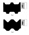
- design feature inventively FIG. 1
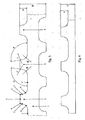
- FIG. 2 State of the art
- FIG. 1 The obtained simulation results were then stored in FIG. 1 and FIG. 2 shown with identical grayscale scaling.
- the comparison shows that the geometry according to the invention FIG. 1 in the unstructured base body has a higher compression density than the geometry of the prior art, according to FIG. 2 ,
- the regions of particularly high density near the channel bottom are also larger for the geometry according to the invention than in the prior art.
- the entire region of the main body of the geometry according to the invention is thus on the one hand, an increased absolute compact density before, which leads to an improvement of the gas-tightness.
- the density gradient over large areas of the body is very low, which reduces the tendency to form a curvature in the subsequent process steps, such as the sintering process.
- the geometry of the invention thus improves the gas-tightness of the overall component, without having to rely on a two-stage pressing process.
- FIG. 3 shows schematically on an enlarged scale a section of an interconnector according to the invention for a fuel cell stack in section.
- the interconnector has a plate-shaped main body -1- with two-sided elevations -2-.
- the average trapezoidal elevations -2- with the height h which may be nub-shaped over the entire extent of the interconnector, continuous ridge-shaped, or segmented web-shaped, form through their interspaces, the channels for the gas supply of the interconnector.
- the final contour -3- each survey -2- over corner rounding -4- or -4'- with a radius r or r 'in inclined side edges with a straight section -5- or 5' over.
- the straight sections -5- and -5'- then go into curved sections -6- and -6'- with a radius R and R 'over. These in turn merge seamlessly into the surface contour -7- or -7'- of the base body -1-.
- the inclined side surfaces include an angle ⁇ or ⁇ 'with the surface contour -7- or -7'- of the main body -1-. It would also be conceivable that with curved sections -6- or -6'- with very large radii R or R ' and small height dimensions h of the elevations -2-, the corner roundings -4- or -4'- directly without the intervening straight sections -5- or -5'- into the curved sections -6- and -6'- lead.
- FIG. 4 shows schematically on an enlarged scale the detail of an end plate according to the invention for a fuel cell stack in section.
- the surveys are the same as with the interconnector FIG. 3 executed, in contrast, however, only on one side of the body.
Landscapes
- Engineering & Computer Science (AREA)
- Chemical & Material Sciences (AREA)
- Mechanical Engineering (AREA)
- Manufacturing & Machinery (AREA)
- Organic Chemistry (AREA)
- Metallurgy (AREA)
- Materials Engineering (AREA)
- Life Sciences & Earth Sciences (AREA)
- Sustainable Development (AREA)
- Sustainable Energy (AREA)
- Chemical Kinetics & Catalysis (AREA)
- Electrochemistry (AREA)
- General Chemical & Material Sciences (AREA)
- Fuel Cell (AREA)
- Powder Metallurgy (AREA)
Abstract
Description
- Durch Pressen und Sintern eines pulverförmigen Ausgangsmaterials hergestelltes Formteil, bestehend aus einem scheiben- oder plattenförmigen Grundkörper mit einer Vielzahl von noppen- und/oder stegförmigen Erhebungen mit einer Höhe h und mit im Querschnitt jeweils zwei geneigten Seitenflanken, welche von einer Endkontur der Erhebung ausgehend, über Eckenrundungen mit einem Radius r bzw. r', unmittelbar oder über dazwischen liegende gerade Abschnitte in kurvenförmige Abschnitte mit einem Radius R bzw. R' münden, welche in die Oberflächenkontur des Grundkörpers übergehen, wobei die geraden Abschnitte, bzw. bei einem unmittelbaren Übergang der Eckenrundungen in die kurvenförmigen Abschnitte, die Tangenten am Punkt des Überganges, einen Neigungswinkel α bzw. α' zur Oberflächenkontur im Bereich von 95° bis 135° aufweisen.
- Ein derartiges Formteil in Form eines Interkonnektors bzw. einer Endplatte für einen Brennstoffzellenstapel ist beispielsweise im AT GM 6.260 oder in der
US 2008/0199738 beschrieben. - Interkonnektoren bzw. Endplatten in einem Brennstoffzellenstapel haben die Funktion von Stromsammlern und müssen gleichzeitig eine sichere Trennung der Reaktionsgase zwischen Anoden- und Kathodenseite sowie die Führung dieser Reaktionsgase gewährleisten. Um diese Aufgabe zu erfüllen, werden die Interkonnektoren bzw. Endplatten als metallische Platten oder Scheiben mit noppen-und/oder stegförmigen Erhebungen ausgeführt. Diese Erhebungen sind bei Endplatten einseitig und bei Interkonnektoren auf beiden Seiten des Grundkörpers ausgeführt. Die Gesamtdicke derartiger Interkonnektoren und Endplatten liegt in der Praxis zwischen 1 und 5 mm. Die erhabenen Strukturen sind elektrische Kontaktbereiche zur elektrochemisch aktiven Zelle hin. Die Zwischenräume zwischen den einzelnen noppen- und stegförmigen Erhebungen dienen dann der Führung der Reaktionsgase. Insgesamt muss der Interkonnektor bzw. die Endplatte über die gesamten Abmessungen eine hohe Dichtigkeit aufweisen, um die sichere Trennung der Reaktionsgase zwischen Anoden- und Kathodenseite zu gewährleisten.
- Die Herstellung der Endform derartiger Interkonnektoren und Endplatten durch spanabhebende Bearbeitung aus Halbzeug ist sehr kostenintensiv, weshalb sich eine pulvermetallurgische Fertigung, durch Pressen pulverförmiger Ausgangsmaterialien möglichst in die Endform und anschließendes Sintern der gepressten Formteile, anzustreben ist.
- Bei der geometrischen Auslegung der Querschnitte für die Gasführung wären an sich rechteckige Querschnitte optimal, da sie einen guten Kompromiss im Hinblick auf maximale Kontaktierungsfläche, bei gleichzeitig ausreichend großem Querschnitt für die Gasführung bilden. Derartige Formen sind jedoch auf pulvermetallurgischem Wege praktisch nicht herstellbar, so dass sich in der Praxis trapezförmige Querschnitte mit geraden, geneigten Flanken und kleinen Übergangsradien sowohl zwischen den Endkonturen der Erhebungen und den geneigten Flanken, als auch zwischen diesen und der Oberflächenkontur des Grundkörpers, durchgesetzt haben.
- Weiterhin problematisch bei der pulvermetallurgischen Herstellung ist es, dass insbesondere bei Interkonnektoren und Endplatten, die bei oxidkeramischen Hochtemperaturbrennstoffzellenstapeln (solid oxide fuel cell bzw. SOFC) zum Einsatz kommen, vielfach Legierungen mit hohen Chromanteilen als Werkstoff verwendet werden. Derartige Legierungen sind aber bei niedrigen Temperaturen äußerst spröde und können nur sehr schwer verpresst werden.
- Um trotz dieser schweren Verpressbarkeit eine ausreichende Dichte und Homogenität der fertigen Interkonnektoren und Endplatten zu gewährleisten, wird entsprechend der AT GM 6.260 ein zweistufiges Pressverfahren unter ganz speziellen Bedingungen vorgeschlagen. Nachteilig dabei ist, dass ein derartiges Pressverfahren kostenaufwändig ist und die erreichte Homogenität des Bauteiles immer noch nicht optimal ist.
- Die Aufgabe der Erfindung ist es, ein durch Pressen und Sintern hergestelltes komplexes strukturiertes Formteil, insbesondere einen Interkonnektor bzw. eine Endplatte für einen Brennstoffzellenstapel zu schaffen, das kostengünstig herstellbar ist und das gleichzeitig eine hohe Dichte, verbunden mit einer möglichst großen Homogenität aufweist.
- Erfindungsgemäß wird dies dadurch erreicht, dass der Radius R bzw. R' im Bereich von 0,15 bis 1 mm liegt und die Höhe h so dimensioniert ist, dass das Verhältnis R : h bzw. R' : h in einem Bereich von 0,25 bis 1 liegt.
- Durch die Erfindung wurde auf überraschende Weise erkannt, dass bei einer Vergrößerung der Übergangsradien der geneigten Seitenflanken zum Grundkörper des Formteiles hin, bei gleichzeitiger Herabsetzung der Höhe h der steg- oder noppenförmigen Erhebungen innerhalb eines ganz speziellen Bereiches, bei der Herstellung des Formteiles, auch durch ein einstufiges Pressverfahren eine sehr hohe Dichte mit geringeren Dichtegradienten und damit eine sehr gleichmäßige Homogenität des Formteiles erreicht wird. Der Übergangsradius r bzw. r' der Endkonturen der Erhebungen zu den geneigten Seitenflächen ist dabei nicht so wesentlich, er wird in der Praxis in einem Bereich zwischen 0,1 und 0,5 mm liegen. Gleichzeitig hat die erfindungsgemäße Ausgestaltung positive Auswirkungen auf die Maßhaltigkeit und Ebenheit des Formteiles während der nachfolgenden Prozessschritte.
- Bei einer Auslegung des Formteiles außerhalb der erfindungsgemäß definierten Grenzen nimmt die Dichte und Homogenität signifikant ab, so dass eine Herstellbarkeit durch ein einstufiges Pressverfahren nicht mehr gewährleistet ist.
- In einer bevorzugten Ausführung der Erfindung liegt der Neigungswinkel α bzw. α' im Bereich von 95° bis 120°, der Radius R bzw. R' im Bereich von 0,3 bis 1 mm und das Verhältnis R: h bzw. R' : h in einem Bereich von 0,5 bis 1.
- Unter diesen Bedingungen werden sehr gute Werte hinsichtlich Dichte und Homogenität des Formteiles erreicht.
- In einer besonders bevorzugten Ausgestaltung der Erfindung liegt der Neigungswinkel α bzw. α' im Bereich von 95° bis 110°, der Radius R bzw. R' im Bereich von 0,3 bis 1 mm und das Verhältnis R : h bzw. R' : h in einem Bereich von 0,7 bis 1.
- Unter diesen Bedingungen werden die besten Werte hinsichtlich Dichte und Homogenität des Formteiles erreicht.
- Insbesondere von Vorteil ist es, wenn die erfindungsgemäße Ausgestaltung eines Formteiles bei Interkonnektoren bzw. Endplatten von Brennstoffzellenstapeln zur Anwendung kommt. In diesem Fall ist auch bei der Anwendung eines kostengünstigen Herstellverfahrens, durch die hohe erzielbare Dichte des Formteiles, die für Interkonnektoren und Endplatten notwendige Dichtigkeit des Bauteiles für die sichere Gastrennung gewährleistet.
- Des weiteren ist die erfindungsgemäße Ausgestaltung des Formteiles dann besonders vorteilhaft, wenn als pulverförmiges Ausgangsmaterial eine Legierung mit mindestens 20 Gew.% Chromanteil, bei Interkonnektoren und Endplatten insbesondere eine Legierung mit 20 bis 30 Gew.% Chrom und 70 bis 80 Gew.% einer Vorlegierung aus Eisen mit 0,5 bis 0,8 Gew.% Seltenerdmetallen, im speziellen Yttrium, oder eine Legierung mit 95 Gew.% Chrom und 5 Gew.% einer Vorlegierung aus Eisen mit 0,5 bis 0,8 Gew.% Yttrium, verwendet wird.
- Im Folgenden wird die Erfindung an Hand von Figuren näher erläutert.
-
Figur 1 zeigt die Dichteverteilung eines erfindungsgemäßen Interkonnektors die durch eine Simulationsberechnung ermittelt wurde. -
Figur 2 zeigt die Dichteverteilung eines Interkonnektors nach dem Stand der Technik, die ebenfalls durch eine Simulationsberechnung ermittelt wurde. - Die Simulationsberechnungen zur Untersuchung des Verdichtungsverhaltens beim erfindungsgemäßen Interkonnektor und beim Interkonnektor nach dem Stand der Technik erfolgte durch FEM-(FINITE ELEMENTE METHODE) Simulation mit Hilfe des Drucker/Prager/Cap-Modells. Als Basisdaten für beide Simulationen wurden die Kennwerte des Ausgangspulvers einer Legierung mit 95 Gew.% Chrom und 5 Gew.% einer Vorlegierung aus Eisen mit 0,8 Gew.% Yttrium, wie Kohäsion und Winkel der inneren Reibung, sowie die kinematische Beschreibung des Pressvorganges, die für beide Simulationen dieselben waren, herangezogen.
- Zusätzlich wurden die unterschiedlichen geometrischen Ausgestaltungsmerkmale entsprechend der nachfolgenden Tabelle herangezogen.
Ausgestaltungsmerkmal erfindungsgemäß
(Figur 1 )Stand der Technik
(Figur 2 )r 0,05 mm 0,05 mm R 0,35 mm 0,01 mm h 0,4 mm 0,6 mm (Oberseite) 0,5 mm (Unterseite) D 2,5 mm 2,5 mm R : h 0,875 0,017 (Oberseite) 0,020 (Unterseite) α 95° 135° - Die erhaltenen Simulationsergebnisse wurden dann in
Figur 1 und Figur 2 mit identischer Graustufenskalierung dargestellt. Der Vergleich zeigt, dass die erfindungsgemäße Geometrie nachFigur 1 im unstrukturierten Grundkörper eine höhere Pressdichte aufweist, als die Geometrie nach dem Stand der Technik, entsprechendFigur 2 . - Die Bereiche besonders hoher Dichte nahe des Kanalgrundes sind für die erfindungsgemäße Geometrie ebenfalls größer als beim Stand der Technik. Im gesamten Bereich des Grundkörpers der erfindungsgemäßen Geometrie liegt damit einerseits eine erhöhte absolute Pressdichte vor, was zu einer Verbesserung der Gasdichtigkeit führt. Andererseits ist der Dichtegradient über weite Bereiche des Grundkörpers sehr gering, was in den nachfolgenden Prozessschritten, wie beispielsweise dem Sinterprozess, die Neigung zur Ausbildung einer Krümmung verringert.
- Die Ergebnisse zeigen deutlich, dass durch die erfindungsgemäße Geometrie eine signifikante Steigerung der Pressdichte und auch der Dichtehomogenität im Grundkörper eines Interkonnektors erreicht werden kann. Die erfindungsgemäße Geometrie verbessert damit die Gasdichtigkeit des Gesamtbauteiles, ohne auf ein zweistufiges Pressverfahren angewiesen zu sein.
-
Figur 3 zeigt schematisch in vergrößertem Maßstab einen Ausschnitt eines erfindungsgemäßen Interkonnektors für einen Brennstoffzellenstapel im Schnitt. Der Interkonnektor weist einen plattenförmigen Grundkörper -1- mit beidseitigen Erhebungen -2- auf. Die im Schnitt trapezförmigen Erhebungen -2- mit der Höhe h, welche über die Gesamterstreckung des Interkonnektors noppenförmig, durchgehend stegförmig, oder auch segmentiert stegförmig ausgebildet sein können, bilden durch ihre Zwischenräume die Kanäle für die Gasführung des Interkonnektors. Die Endkontur -3- jeder Erhebung -2- geht über Eckenrundungen -4- bzw. -4'- mit einem Radius r bzw. r' in geneigte Seitenflanken mit einem geraden Abschnitt -5- bzw. 5' über. Die geraden Abschnitte -5- bzw. -5'- gehen dann in kurvenförmige Abschnitte -6- bzw. -6'- mit einem Radius R bzw. R' über. Diese wiederum gehen dann übergangslos in die Oberflächenkontur -7- bzw. -7'- des Grundkörpers -1- über. - Die geneigten Seitenflächen schließen einen Winkel α bzw. α' mit der Oberflächenkontur -7- bzw. -7'- des Grundkörpers -1- ein. Ebenso wäre es denkbar, dass bei kurvenförmigen Abschnitten -6- bzw. -6'- mit sehr großen Radien R bzw. R' und kleinen Höhenabmessungen h der Erhebungen -2-, die Eckenrundungen -4- bzw. -4'- direkt ohne die dazwischen liegenden geraden Abschnitte -5- bzw. -5'- in die kurvenförmigen Abschnitte -6- bzw. -6'- münden. In diesem Fall schließen die Tangenten an den Übergängen der Eckenrundungen -4- bzw. -4'- in die kurvenförmigen Abschnitte -6- bzw. -6'-, die Neigungswinkel α bzw. α' mit der Oberflächenkontur -7- bzw. -7'- des Grundkörpers -1- ein.
-
Figur 4 zeigt schematisch in vergrößertem Maßstab den Ausschnitt einer erfindungsgemäßen Endplatte für einen Brennstoffzellenstapel im Schnitt. Die Erhebungen sind genauso wie beim Interkonnektor nachFigur 3 ausgeführt, im Unterschied dazu jedoch nur auf einer Seite des Grundkörpers.
Claims (7)
- Durch Pressen und Sintern eines pulverförmigen Ausgangsmaterials hergestelltes Formteil, bestehend aus einem scheiben- oder plattenförmigen Grundkörper (1) mit einer Vielzahl von noppen- und/oder stegförmigen Erhebungen (2) mit einer Höhe h und mit im Querschnitt jeweils zwei geneigten Seitenflanken, welche von einer Endkontur (3) der Erhebung (2) ausgehend; über Eckenrundungen (4,4') mit einem Radius r bzw. r'; unmittelbar oder über dazwischen liegende gerade Abschnitte (5,5') in kurvenförmige Abschnitte (6,6') mit einem Radius R,R' münden, welche in die Oberflächenkontur (7,7') des Grundkörpers (1) übergehen, wobei die geraden Abschnitte (5,5'), bzw. bei einem unmittelbaren Übergang der Eckenrundungen (4,4') in die kurvenförmigen Abschnitte (6,6'), die Tangenten am Punkt des Überganges, einen Neigungswinkel α bzw. α' zur Oberflächenkontur (7,7') im Bereich von 95° bis 135° aufweisen,
dadurch gekennzeichnet,
dass der Radius R bzw. R' im Bereich von 0,15 bis 1 mm liegt und die Höhe h so dimensioniert ist, dass das Verhältnis R : h bzw. R' : h in einem Bereich von 0,25 bis 1 liegt. - Durch Pressen und Sintern eines pulverförmigen Ausgangsmaterials hergestelltes Formteil nach Anspruch 1, dadurch gekennzeichnet, dass der Neigungswinkel α,α' im Bereich von 95° bis 120°, der Radius R bzw. R' im Bereich von 0,3 bis 1 mm und das Verhältnis R : h bzw. R' : h in einem Bereich von 0,5 bis 1 liegt.
- Durch Pressen und Sintern eines pulverförmigen Ausgangsmaterials hergestelltes Formteil nach Anspruch 1, dadurch gekennzeichnet, dass der Neigungswinkel α,α' im Bereich von 95° bis 110°, der Radius R bzw. R' im Bereich von 0,3 bis 1 mm und das Verhältnis R : h bzw. R' : h in einem Bereich von 0,7 bis 1 liegt.
- Durch Pressen und Sintern eines pulverförmigen Ausgangsmaterials hergestelltes Formteil nach einem der Ansprüche 1 bis 3, dadurch gekennzeichnet, dass das Formteil der Interkonnektor oder die Endplatte eines Brennstoffzellenstapels ist.
- Durch Pressen und Sintern eines pulverförmigen Ausgangsmaterials hergestelltes Formteil nach einem der Ansprüche 1 bis 4, dadurch gekennzeichnet, dass das pulverförmige Ausgangsmaterial eine Legierung mit mindestens 20 Gew.% Chromanteil ist.
- Durch Pressen und Sintern eines pulverförmigen Ausgangsmaterials hergestellter Interkonnektor bzw. Endplatte nach Anspruch 4, dadurch gekennzeichnet, dass das pulverförmige Ausgangsmaterial aus 20 bis 30 Gew.% Chrom und 70 bis 80 Gew.% einer Vorlegierung aus Eisen mit 0,5 bis 0,8 Gew.% Seltenerdmetallen, insbesondere Yttrium, besteht.
- Durch Pressen und Sintern eines pulverförmigen Ausgangsmaterials hergestellter Interkonnektor bzw. Endplatte nach Anspruch 3, dadurch gekennzeichnet, dass das pulverförmige Ausgangsmaterial aus 95 Gew.% Chrom und 5 Gew.% einer Vorlegierung aus Eisen mit 0,5 bis 0,8 Gew.% Yttrium besteht.
Applications Claiming Priority (1)
| Application Number | Priority Date | Filing Date | Title |
|---|---|---|---|
| AT0079409U AT11799U1 (de) | 2009-12-15 | 2009-12-15 | Formteil |
Publications (2)
| Publication Number | Publication Date |
|---|---|
| EP2337130A1 true EP2337130A1 (de) | 2011-06-22 |
| EP2337130B1 EP2337130B1 (de) | 2018-02-07 |
Family
ID=43646237
Family Applications (1)
| Application Number | Title | Priority Date | Filing Date |
|---|---|---|---|
| EP10015585.2A Active EP2337130B1 (de) | 2009-12-15 | 2010-12-14 | Formteil |
Country Status (9)
| Country | Link |
|---|---|
| US (2) | US8753785B2 (de) |
| EP (1) | EP2337130B1 (de) |
| JP (1) | JP5744500B2 (de) |
| KR (1) | KR101330477B1 (de) |
| CN (1) | CN102097629B (de) |
| AT (1) | AT11799U1 (de) |
| CA (1) | CA2724350C (de) |
| DK (1) | DK2337130T3 (de) |
| TW (1) | TWI481457B (de) |
Cited By (1)
| Publication number | Priority date | Publication date | Assignee | Title |
|---|---|---|---|---|
| WO2013010198A1 (de) | 2011-07-21 | 2013-01-24 | Plansee Se | Formteil |
Families Citing this family (17)
| Publication number | Priority date | Publication date | Assignee | Title |
|---|---|---|---|---|
| US8840833B1 (en) | 2010-11-30 | 2014-09-23 | Bloom Energy Corporation | Iron coated chromium powder and SOFC IC made therefrom |
| CA2840022C (en) | 2011-06-28 | 2018-09-18 | Morimura Sofc Technology Co., Ltd. | Solid oxide fuel cell and inter-connector |
| AU2011376555B2 (en) * | 2011-09-07 | 2016-12-01 | Haldor Topsoe A/S | Fuel cell stack with thin endplate with integrated gas distribution tubes |
| US8962219B2 (en) | 2011-11-18 | 2015-02-24 | Bloom Energy Corporation | Fuel cell interconnects and methods of fabrication |
| US9452475B2 (en) | 2012-03-01 | 2016-09-27 | Bloom Energy Corporation | Coatings for SOFC metallic interconnects |
| US9847520B1 (en) | 2012-07-19 | 2017-12-19 | Bloom Energy Corporation | Thermal processing of interconnects |
| US11217797B2 (en) | 2012-08-29 | 2022-01-04 | Bloom Energy Corporation | Interconnect for fuel cell stack |
| US9478812B1 (en) | 2012-10-17 | 2016-10-25 | Bloom Energy Corporation | Interconnect for fuel cell stack |
| US9368810B2 (en) | 2012-11-06 | 2016-06-14 | Bloom Energy Corporation | Interconnect and end plate design for fuel cell stack |
| JP5601673B1 (ja) * | 2013-02-26 | 2014-10-08 | 日本碍子株式会社 | 燃料電池 |
| AT513501B1 (de) | 2013-09-02 | 2014-05-15 | Abatec Group Ag | IR-Strahler mit Doppelverglasung |
| WO2015050855A1 (en) | 2013-10-01 | 2015-04-09 | Bloom Energy Corporation | Pre-formed powder delivery to powder press machine |
| US10079393B1 (en) | 2014-01-09 | 2018-09-18 | Bloom Energy Corporation | Method of fabricating an interconnect for a fuel cell stack |
| WO2015130644A1 (en) | 2014-02-25 | 2015-09-03 | Bloom Energy Corporation | Composition and processing of metallic interconnects for sofc stacks |
| US9992917B2 (en) | 2014-03-10 | 2018-06-05 | Vulcan GMS | 3-D printing method for producing tungsten-based shielding parts |
| CN114927738B (zh) * | 2022-05-24 | 2024-05-24 | 中汽创智科技有限公司 | 一种燃料电池电堆装配结构 |
| WO2025257962A1 (ja) * | 2024-06-12 | 2025-12-18 | 住友電気工業株式会社 | 金属多孔体シート、燃料電池及び水素製造装置 |
Citations (3)
| Publication number | Priority date | Publication date | Assignee | Title |
|---|---|---|---|---|
| WO2002055747A1 (de) * | 2001-01-15 | 2002-07-18 | Plansee Aktiengesellschaft | Pulvermetallurgisches verfahren zur herstellung hochdichter formteile |
| AT6260U1 (de) * | 2002-08-01 | 2003-07-25 | Plansee Ag | Verfahren zur herstellung eines formteiles |
| US20080199738A1 (en) | 2007-02-16 | 2008-08-21 | Bloom Energy Corporation | Solid oxide fuel cell interconnect |
Family Cites Families (40)
| Publication number | Priority date | Publication date | Assignee | Title |
|---|---|---|---|---|
| JPS5960971A (ja) * | 1982-09-30 | 1984-04-07 | Toshiba Corp | 電気化学発電素子 |
| JPS6328252U (de) * | 1986-08-08 | 1988-02-24 | ||
| US6885864B2 (en) * | 1992-03-06 | 2005-04-26 | Aircell, Inc. | Virtual private network for cellular communications |
| IT1278752B1 (it) * | 1995-08-22 | 1997-11-27 | Gregorio Amore | Sistema costruttivo costituito da profilati formati a freddo con lembi ondulati a passo costante, e dispositivi di accoppiamento e fissaggio |
| JPH09189321A (ja) * | 1996-01-09 | 1997-07-22 | Hitachi Powdered Metals Co Ltd | 焼結コネクチングロッドの製造方法および粉末成形金型 |
| JPH1040937A (ja) * | 1996-07-18 | 1998-02-13 | Toyota Motor Corp | 燃料電池用集電体の製造方法および製造装置 |
| JP3437936B2 (ja) * | 1998-04-07 | 2003-08-18 | 日立化成工業株式会社 | リブ付き燃料電池セパレータ、その製造法及び燃料電池 |
| US6496702B1 (en) * | 1999-08-06 | 2002-12-17 | Genesys Telecommunications Laboratories, Inc. | Method and apparatus for providing enhanced communication capability for mobile devices on a virtual private network (VPN) |
| JP4201466B2 (ja) * | 2000-07-26 | 2008-12-24 | 富士通株式会社 | モバイルipネットワークにおけるvpnシステム及びvpnの設定方法 |
| US7155518B2 (en) * | 2001-01-08 | 2006-12-26 | Interactive People Unplugged Ab | Extranet workgroup formation across multiple mobile virtual private networks |
| ITMI20021463A1 (it) * | 2001-07-03 | 2004-01-02 | Samsung Electronics Co Ltd | Procedimento per la trasmissione di dati dal server di una rete privata virtuale ad un nodo mobile |
| KR100407324B1 (ko) * | 2001-10-26 | 2003-11-28 | 삼성전자주식회사 | 가상 사설 네트워크에서 서버가 이동 통신 단말기로데이터를 전송하는 방법 |
| US7536720B2 (en) * | 2002-05-07 | 2009-05-19 | Nortel Networks Limited | Method and apparatus for accelerating CPE-based VPN transmissions over a wireless network |
| US7246232B2 (en) * | 2002-05-31 | 2007-07-17 | Sri International | Methods and apparatus for scalable distributed management of wireless virtual private networks |
| US20060182083A1 (en) * | 2002-10-17 | 2006-08-17 | Junya Nakata | Secured virtual private network with mobile nodes |
| US7616597B2 (en) * | 2002-12-19 | 2009-11-10 | Intel Corporation | System and method for integrating mobile networking with security-based VPNs |
| US20040168051A1 (en) * | 2003-02-26 | 2004-08-26 | Lucent Technologies Inc. | Optimally provisioning connectivity for network-based mobile virtual private network (VPN) services |
| KR100543451B1 (ko) * | 2003-04-17 | 2006-01-23 | 삼성전자주식회사 | 가상 사설망 기능과 무선 랜 기능을 갖는 복합 네트워크장치 및 구현 방법 |
| JP2005050566A (ja) * | 2003-07-29 | 2005-02-24 | Nissan Motor Co Ltd | 燃料電池用セパレータ |
| TWI236255B (en) * | 2003-12-15 | 2005-07-11 | Ind Tech Res Inst | System and method for supporting inter-NAT-domain handoff within a VPN by associating L2TP with mobile IP |
| KR20050090902A (ko) * | 2004-03-10 | 2005-09-14 | 삼성전자주식회사 | 무선 통신 시스템에서 패킷데이터 프로토콜에 따른 vpn서비스 방법 및 장치 |
| US7457626B2 (en) * | 2004-03-19 | 2008-11-25 | Microsoft Corporation | Virtual private network structure reuse for mobile computing devices |
| US20060023861A1 (en) * | 2004-07-27 | 2006-02-02 | Greg Carlson | Effecting VPN capability among wireless subscribers |
| US7477626B2 (en) * | 2004-09-24 | 2009-01-13 | Zyxel Communications Corporation | Apparatus of dynamically assigning external home agent for mobile virtual private networks and method for the same |
| US7486951B2 (en) * | 2004-09-24 | 2009-02-03 | Zyxel Communications Corporation | Apparatus of dynamically assigning external home agent for mobile virtual private networks and method for the same |
| KR100918440B1 (ko) * | 2004-11-12 | 2009-09-24 | 삼성전자주식회사 | 가상 사설망에서 게이트웨이의 ip 주소를 이용한 이동 단말의 통신 방법 및 장치 |
| JP2009510808A (ja) * | 2005-02-18 | 2009-03-12 | クレダント テクノロジーズ、インク. | インテリジェンスベースのセキュリティのシステムおよび方法 |
| US7376113B2 (en) * | 2005-04-01 | 2008-05-20 | Arubs Networks, Inc. | Mechanism for securely extending a private network |
| US20060230445A1 (en) * | 2005-04-06 | 2006-10-12 | Shun-Chao Huang | Mobile VPN proxy method based on session initiation protocol |
| US8411650B2 (en) * | 2005-04-18 | 2013-04-02 | Cisco Technology, Inc. | Method and system for providing virtual private network services through a mobile IP home agent |
| US20070006295A1 (en) * | 2005-06-24 | 2007-01-04 | Henry Haverinen | Adaptive IPsec processing in mobile-enhanced virtual private networks |
| US7602786B2 (en) * | 2005-07-07 | 2009-10-13 | Cisco Technology, Inc. | Methods and apparatus for optimizing mobile VPN communications |
| US20070177550A1 (en) * | 2005-07-12 | 2007-08-02 | Hyeok Chan Kwon | Method for providing virtual private network services to mobile node in IPv6 network and gateway using the same |
| US7882557B2 (en) * | 2005-11-23 | 2011-02-01 | Research In Motion Limited | System and method to provide built-in and mobile VPN connectivity |
| US20070124803A1 (en) * | 2005-11-29 | 2007-05-31 | Nortel Networks Limited | Method and apparatus for rating a compliance level of a computer connecting to a network |
| US20070203572A1 (en) * | 2006-01-25 | 2007-08-30 | Heuser Richard R | Catheter system with stent apparatus for connecting adjacent blood vessels |
| WO2008079141A1 (en) * | 2006-12-27 | 2008-07-03 | Utc Power Corporation | Asymmetric dovetail interconnect for solid oxide fuel cell |
| EP1993254A1 (de) * | 2007-05-16 | 2008-11-19 | Doga Armangil | Verfahren und System für die Zusammensetzung von Diensten |
| US7979565B2 (en) * | 2008-08-27 | 2011-07-12 | International Business Machines Corporation | System and method to provide a network service |
| JP2010269572A (ja) * | 2009-05-25 | 2010-12-02 | Idemitsu Kosan Co Ltd | 成形品の製造方法、金型および成形品 |
-
2009
- 2009-12-15 AT AT0079409U patent/AT11799U1/de not_active IP Right Cessation
-
2010
- 2010-11-30 TW TW099141390A patent/TWI481457B/zh active
- 2010-12-08 CA CA 2724350 patent/CA2724350C/en active Active
- 2010-12-10 JP JP2010275921A patent/JP5744500B2/ja active Active
- 2010-12-14 KR KR1020100127739A patent/KR101330477B1/ko active Active
- 2010-12-14 EP EP10015585.2A patent/EP2337130B1/de active Active
- 2010-12-14 DK DK10015585.2T patent/DK2337130T3/en active
- 2010-12-15 US US12/969,067 patent/US8753785B2/en active Active
- 2010-12-15 CN CN201010609938.5A patent/CN102097629B/zh active Active
-
2014
- 2014-03-11 US US14/204,500 patent/US8802328B2/en active Active
Patent Citations (3)
| Publication number | Priority date | Publication date | Assignee | Title |
|---|---|---|---|---|
| WO2002055747A1 (de) * | 2001-01-15 | 2002-07-18 | Plansee Aktiengesellschaft | Pulvermetallurgisches verfahren zur herstellung hochdichter formteile |
| AT6260U1 (de) * | 2002-08-01 | 2003-07-25 | Plansee Ag | Verfahren zur herstellung eines formteiles |
| US20080199738A1 (en) | 2007-02-16 | 2008-08-21 | Bloom Energy Corporation | Solid oxide fuel cell interconnect |
Cited By (2)
| Publication number | Priority date | Publication date | Assignee | Title |
|---|---|---|---|---|
| WO2013010198A1 (de) | 2011-07-21 | 2013-01-24 | Plansee Se | Formteil |
| US9472816B2 (en) | 2011-07-21 | 2016-10-18 | Plansee Se | Molded part |
Also Published As
| Publication number | Publication date |
|---|---|
| CA2724350C (en) | 2015-04-28 |
| AT11799U1 (de) | 2011-05-15 |
| CN102097629B (zh) | 2014-07-02 |
| TW201130585A (en) | 2011-09-16 |
| TWI481457B (zh) | 2015-04-21 |
| KR101330477B1 (ko) | 2013-11-15 |
| US20140193287A1 (en) | 2014-07-10 |
| CN102097629A (zh) | 2011-06-15 |
| US8802328B2 (en) | 2014-08-12 |
| JP5744500B2 (ja) | 2015-07-08 |
| CA2724350A1 (en) | 2011-06-15 |
| DK2337130T3 (en) | 2018-05-28 |
| JP2011129520A (ja) | 2011-06-30 |
| KR20110068908A (ko) | 2011-06-22 |
| US8753785B2 (en) | 2014-06-17 |
| EP2337130B1 (de) | 2018-02-07 |
| US20110143261A1 (en) | 2011-06-16 |
Similar Documents
| Publication | Publication Date | Title |
|---|---|---|
| EP2337130B1 (de) | Formteil | |
| EP2734323B1 (de) | Formteil | |
| EP3442730B1 (de) | Verfahren zur herstellung von metallischen oder keramischen trägersubstraten sowie trägersubstrate | |
| DE102018102314B4 (de) | Matrizenanordnung für eine prägepresse | |
| AT6260U1 (de) | Verfahren zur herstellung eines formteiles | |
| DE102014005930A1 (de) | Hybride Bipolarplatten-Anordnung für Brennstoffzellen | |
| DE102013114189A1 (de) | Einzigartiges Vorform-Design zum zweistufigen Formen von Edelstahl-Brennstoffzellen-Bipolarplatten | |
| EP0670963A1 (de) | Elektrochemischer aktor. | |
| EP3031093B1 (de) | Verfahren zur herstellung einer brennstoffzelle und eines brennstoffzellensystems | |
| DE10328039B4 (de) | Elektrochemische Anordnung mit elastischer Verteilungsstruktur | |
| AT4737U1 (de) | Pulvermetallurgisches verfahren zur herstellung hochdichter formteile | |
| DE102008033209A1 (de) | Brennstoffzellenanordnung | |
| EP3042413B1 (de) | Pulvermetallurgisches formteil als interkonnektor oder endplatte für eine elektrochemische zelle | |
| DE19832625C2 (de) | Verfahren zur Herstellung eines Stapelreaktors und Stapelreaktor zur Wasserstofferzeugung aus Kohlenwasserstoffen | |
| EP1903629A2 (de) | Scheibenelement für eine Stromabnehmerplatte oder Bipolarplatte einer Brennstoffzelle | |
| DE102005005116A1 (de) | Interkonnektor für Hochtemperaturbrennstoffzellen | |
| EP4200928A1 (de) | Bipolarplatte und verfahren zur herstellung | |
| EP2850687B1 (de) | Elektrischer energiespeicher | |
| DE102015015876A1 (de) | Separatorplatte für eine Brennstoffzelle, Brennstoffzelle, Fahrzeug und Verfahren zum Fertigen einer Separatorplatte | |
| DE102015012646A1 (de) | Verfahren zum Herstellen komplexer Bipolarplatten für Brennstoffzellen durch Nutzen des Extrudierens | |
| DE102011080514A1 (de) | Verfahren zur Herstellung von maßgenauen Sinterkörpern aus Grundmaterialien mit naturgemäß hohem Schwundverhalten | |
| DE19643157C1 (de) | Verfahren zur Herstellung eines Chrom-Werkstoffes | |
| DE112021008493T5 (de) | Bipolarplatte für brennstoffzellen und verfahren zu ihrer herstellung | |
| DE102025101158A1 (de) | Verfahren zur Herstellung einer Kühlvorrichtung | |
| WO2023232658A1 (de) | Separatorplattenhälfte, separatorplatte, elektrochemischer energiewandler sowie verfahren zum herstellen einer separatorplattenhälfte |
Legal Events
| Date | Code | Title | Description |
|---|---|---|---|
| PUAI | Public reference made under article 153(3) epc to a published international application that has entered the european phase |
Free format text: ORIGINAL CODE: 0009012 |
|
| AK | Designated contracting states |
Kind code of ref document: A1 Designated state(s): AL AT BE BG CH CY CZ DE DK EE ES FI FR GB GR HR HU IE IS IT LI LT LU LV MC MK MT NL NO PL PT RO RS SE SI SK SM TR |
|
| AX | Request for extension of the european patent |
Extension state: BA ME |
|
| RIN1 | Information on inventor provided before grant (corrected) |
Inventor name: LEUPRECHT, ALEXANDER Inventor name: BRANDNER, MARCO, DR. Inventor name: VENSKUTONIS, ANDREAS, DR. Inventor name: GERZOSKOVITZ, STEFAN Inventor name: KRAUSSLER, WOLFGANG |
|
| 17P | Request for examination filed |
Effective date: 20111110 |
|
| GRAP | Despatch of communication of intention to grant a patent |
Free format text: ORIGINAL CODE: EPIDOSNIGR1 |
|
| RIC1 | Information provided on ipc code assigned before grant |
Ipc: H01M 8/0206 20160101ALI20170811BHEP Ipc: H01M 8/021 20160101ALI20170811BHEP Ipc: B22F 5/08 20060101ALI20170811BHEP Ipc: C22C 27/06 20060101ALI20170811BHEP Ipc: C22C 33/02 20060101ALI20170811BHEP Ipc: B22F 3/02 20060101ALI20170811BHEP Ipc: H01M 8/02 20160101AFI20170811BHEP |
|
| INTG | Intention to grant announced |
Effective date: 20170913 |
|
| GRAS | Grant fee paid |
Free format text: ORIGINAL CODE: EPIDOSNIGR3 |
|
| GRAA | (expected) grant |
Free format text: ORIGINAL CODE: 0009210 |
|
| AK | Designated contracting states |
Kind code of ref document: B1 Designated state(s): AL AT BE BG CH CY CZ DE DK EE ES FI FR GB GR HR HU IE IS IT LI LT LU LV MC MK MT NL NO PL PT RO RS SE SI SK SM TR |
|
| REG | Reference to a national code |
Ref country code: GB Ref legal event code: FG4D Free format text: NOT ENGLISH |
|
| REG | Reference to a national code |
Ref country code: AT Ref legal event code: REF Ref document number: 969121 Country of ref document: AT Kind code of ref document: T Effective date: 20180215 Ref country code: CH Ref legal event code: EP |
|
| REG | Reference to a national code |
Ref country code: IE Ref legal event code: FG4D Free format text: LANGUAGE OF EP DOCUMENT: GERMAN |
|
| REG | Reference to a national code |
Ref country code: DE Ref legal event code: R096 Ref document number: 502010014632 Country of ref document: DE |
|
| REG | Reference to a national code |
Ref country code: DK Ref legal event code: T3 Effective date: 20180522 |
|
| REG | Reference to a national code |
Ref country code: SE Ref legal event code: TRGR |
|
| REG | Reference to a national code |
Ref country code: NL Ref legal event code: MP Effective date: 20180207 |
|
| PG25 | Lapsed in a contracting state [announced via postgrant information from national office to epo] |
Ref country code: ES Free format text: LAPSE BECAUSE OF FAILURE TO SUBMIT A TRANSLATION OF THE DESCRIPTION OR TO PAY THE FEE WITHIN THE PRESCRIBED TIME-LIMIT Effective date: 20180207 Ref country code: NL Free format text: LAPSE BECAUSE OF FAILURE TO SUBMIT A TRANSLATION OF THE DESCRIPTION OR TO PAY THE FEE WITHIN THE PRESCRIBED TIME-LIMIT Effective date: 20180207 Ref country code: CY Free format text: LAPSE BECAUSE OF FAILURE TO SUBMIT A TRANSLATION OF THE DESCRIPTION OR TO PAY THE FEE WITHIN THE PRESCRIBED TIME-LIMIT Effective date: 20180207 Ref country code: LT Free format text: LAPSE BECAUSE OF FAILURE TO SUBMIT A TRANSLATION OF THE DESCRIPTION OR TO PAY THE FEE WITHIN THE PRESCRIBED TIME-LIMIT Effective date: 20180207 Ref country code: NO Free format text: LAPSE BECAUSE OF FAILURE TO SUBMIT A TRANSLATION OF THE DESCRIPTION OR TO PAY THE FEE WITHIN THE PRESCRIBED TIME-LIMIT Effective date: 20180507 Ref country code: HR Free format text: LAPSE BECAUSE OF FAILURE TO SUBMIT A TRANSLATION OF THE DESCRIPTION OR TO PAY THE FEE WITHIN THE PRESCRIBED TIME-LIMIT Effective date: 20180207 |
|
| PG25 | Lapsed in a contracting state [announced via postgrant information from national office to epo] |
Ref country code: RS Free format text: LAPSE BECAUSE OF FAILURE TO SUBMIT A TRANSLATION OF THE DESCRIPTION OR TO PAY THE FEE WITHIN THE PRESCRIBED TIME-LIMIT Effective date: 20180207 Ref country code: GR Free format text: LAPSE BECAUSE OF FAILURE TO SUBMIT A TRANSLATION OF THE DESCRIPTION OR TO PAY THE FEE WITHIN THE PRESCRIBED TIME-LIMIT Effective date: 20180508 Ref country code: PL Free format text: LAPSE BECAUSE OF FAILURE TO SUBMIT A TRANSLATION OF THE DESCRIPTION OR TO PAY THE FEE WITHIN THE PRESCRIBED TIME-LIMIT Effective date: 20180207 Ref country code: BG Free format text: LAPSE BECAUSE OF FAILURE TO SUBMIT A TRANSLATION OF THE DESCRIPTION OR TO PAY THE FEE WITHIN THE PRESCRIBED TIME-LIMIT Effective date: 20180507 Ref country code: LV Free format text: LAPSE BECAUSE OF FAILURE TO SUBMIT A TRANSLATION OF THE DESCRIPTION OR TO PAY THE FEE WITHIN THE PRESCRIBED TIME-LIMIT Effective date: 20180207 Ref country code: IS Free format text: LAPSE BECAUSE OF FAILURE TO SUBMIT A TRANSLATION OF THE DESCRIPTION OR TO PAY THE FEE WITHIN THE PRESCRIBED TIME-LIMIT Effective date: 20180607 |
|
| PG25 | Lapsed in a contracting state [announced via postgrant information from national office to epo] |
Ref country code: MT Free format text: LAPSE BECAUSE OF FAILURE TO SUBMIT A TRANSLATION OF THE DESCRIPTION OR TO PAY THE FEE WITHIN THE PRESCRIBED TIME-LIMIT Effective date: 20180207 |
|
| PG25 | Lapsed in a contracting state [announced via postgrant information from national office to epo] |
Ref country code: AL Free format text: LAPSE BECAUSE OF FAILURE TO SUBMIT A TRANSLATION OF THE DESCRIPTION OR TO PAY THE FEE WITHIN THE PRESCRIBED TIME-LIMIT Effective date: 20180207 Ref country code: EE Free format text: LAPSE BECAUSE OF FAILURE TO SUBMIT A TRANSLATION OF THE DESCRIPTION OR TO PAY THE FEE WITHIN THE PRESCRIBED TIME-LIMIT Effective date: 20180207 Ref country code: RO Free format text: LAPSE BECAUSE OF FAILURE TO SUBMIT A TRANSLATION OF THE DESCRIPTION OR TO PAY THE FEE WITHIN THE PRESCRIBED TIME-LIMIT Effective date: 20180207 |
|
| REG | Reference to a national code |
Ref country code: DE Ref legal event code: R097 Ref document number: 502010014632 Country of ref document: DE |
|
| PG25 | Lapsed in a contracting state [announced via postgrant information from national office to epo] |
Ref country code: SM Free format text: LAPSE BECAUSE OF FAILURE TO SUBMIT A TRANSLATION OF THE DESCRIPTION OR TO PAY THE FEE WITHIN THE PRESCRIBED TIME-LIMIT Effective date: 20180207 Ref country code: SK Free format text: LAPSE BECAUSE OF FAILURE TO SUBMIT A TRANSLATION OF THE DESCRIPTION OR TO PAY THE FEE WITHIN THE PRESCRIBED TIME-LIMIT Effective date: 20180207 Ref country code: CZ Free format text: LAPSE BECAUSE OF FAILURE TO SUBMIT A TRANSLATION OF THE DESCRIPTION OR TO PAY THE FEE WITHIN THE PRESCRIBED TIME-LIMIT Effective date: 20180207 |
|
| PLBE | No opposition filed within time limit |
Free format text: ORIGINAL CODE: 0009261 |
|
| STAA | Information on the status of an ep patent application or granted ep patent |
Free format text: STATUS: NO OPPOSITION FILED WITHIN TIME LIMIT |
|
| 26N | No opposition filed |
Effective date: 20181108 |
|
| PG25 | Lapsed in a contracting state [announced via postgrant information from national office to epo] |
Ref country code: SI Free format text: LAPSE BECAUSE OF FAILURE TO SUBMIT A TRANSLATION OF THE DESCRIPTION OR TO PAY THE FEE WITHIN THE PRESCRIBED TIME-LIMIT Effective date: 20180207 |
|
| PG25 | Lapsed in a contracting state [announced via postgrant information from national office to epo] |
Ref country code: MC Free format text: LAPSE BECAUSE OF FAILURE TO SUBMIT A TRANSLATION OF THE DESCRIPTION OR TO PAY THE FEE WITHIN THE PRESCRIBED TIME-LIMIT Effective date: 20180207 Ref country code: LU Free format text: LAPSE BECAUSE OF NON-PAYMENT OF DUE FEES Effective date: 20181214 |
|
| REG | Reference to a national code |
Ref country code: IE Ref legal event code: MM4A |
|
| REG | Reference to a national code |
Ref country code: BE Ref legal event code: MM Effective date: 20181231 |
|
| PG25 | Lapsed in a contracting state [announced via postgrant information from national office to epo] |
Ref country code: IE Free format text: LAPSE BECAUSE OF NON-PAYMENT OF DUE FEES Effective date: 20181214 |
|
| PG25 | Lapsed in a contracting state [announced via postgrant information from national office to epo] |
Ref country code: BE Free format text: LAPSE BECAUSE OF NON-PAYMENT OF DUE FEES Effective date: 20181231 |
|
| PG25 | Lapsed in a contracting state [announced via postgrant information from national office to epo] |
Ref country code: TR Free format text: LAPSE BECAUSE OF FAILURE TO SUBMIT A TRANSLATION OF THE DESCRIPTION OR TO PAY THE FEE WITHIN THE PRESCRIBED TIME-LIMIT Effective date: 20180207 |
|
| PG25 | Lapsed in a contracting state [announced via postgrant information from national office to epo] |
Ref country code: PT Free format text: LAPSE BECAUSE OF FAILURE TO SUBMIT A TRANSLATION OF THE DESCRIPTION OR TO PAY THE FEE WITHIN THE PRESCRIBED TIME-LIMIT Effective date: 20180207 |
|
| PG25 | Lapsed in a contracting state [announced via postgrant information from national office to epo] |
Ref country code: MK Free format text: LAPSE BECAUSE OF NON-PAYMENT OF DUE FEES Effective date: 20180207 Ref country code: HU Free format text: LAPSE BECAUSE OF FAILURE TO SUBMIT A TRANSLATION OF THE DESCRIPTION OR TO PAY THE FEE WITHIN THE PRESCRIBED TIME-LIMIT; INVALID AB INITIO Effective date: 20101214 |
|
| REG | Reference to a national code |
Ref country code: CH Ref legal event code: U11 Free format text: ST27 STATUS EVENT CODE: U-0-0-U10-U11 (AS PROVIDED BY THE NATIONAL OFFICE) Effective date: 20260101 |
|
| PGFP | Annual fee paid to national office [announced via postgrant information from national office to epo] |
Ref country code: DE Payment date: 20251211 Year of fee payment: 16 |
|
| PGFP | Annual fee paid to national office [announced via postgrant information from national office to epo] |
Ref country code: GB Payment date: 20251219 Year of fee payment: 16 |
|
| PGFP | Annual fee paid to national office [announced via postgrant information from national office to epo] |
Ref country code: AT Payment date: 20251222 Year of fee payment: 16 |
|
| PGFP | Annual fee paid to national office [announced via postgrant information from national office to epo] |
Ref country code: IT Payment date: 20251223 Year of fee payment: 16 Ref country code: FI Payment date: 20251223 Year of fee payment: 16 Ref country code: DK Payment date: 20251224 Year of fee payment: 16 |
|
| PGFP | Annual fee paid to national office [announced via postgrant information from national office to epo] |
Ref country code: FR Payment date: 20251222 Year of fee payment: 16 |
|
| PGFP | Annual fee paid to national office [announced via postgrant information from national office to epo] |
Ref country code: SE Payment date: 20251219 Year of fee payment: 16 |
|
| PGFP | Annual fee paid to national office [announced via postgrant information from national office to epo] |
Ref country code: CH Payment date: 20260101 Year of fee payment: 16 |