EP2337215B1 - Verfahren und Vorrichtung zur Steuerung der effektiven Spannung an einem elektrischen Verbraucher - Google Patents
Verfahren und Vorrichtung zur Steuerung der effektiven Spannung an einem elektrischen Verbraucher Download PDFInfo
- Publication number
- EP2337215B1 EP2337215B1 EP09015593A EP09015593A EP2337215B1 EP 2337215 B1 EP2337215 B1 EP 2337215B1 EP 09015593 A EP09015593 A EP 09015593A EP 09015593 A EP09015593 A EP 09015593A EP 2337215 B1 EP2337215 B1 EP 2337215B1
- Authority
- EP
- European Patent Office
- Prior art keywords
- capacitor
- triac
- electrical consumer
- switching device
- control device
- Prior art date
- Legal status (The legal status is an assumption and is not a legal conclusion. Google has not performed a legal analysis and makes no representation as to the accuracy of the status listed.)
- Not-in-force
Links
- 238000000034 method Methods 0.000 title claims abstract description 11
- 239000003990 capacitor Substances 0.000 claims abstract description 28
- 230000001629 suppression Effects 0.000 claims abstract description 6
- 230000005669 field effect Effects 0.000 claims description 4
- 230000000694 effects Effects 0.000 claims 2
- 230000001939 inductive effect Effects 0.000 description 3
- 230000001419 dependent effect Effects 0.000 description 1
- 231100001261 hazardous Toxicity 0.000 description 1
Images

Classifications
-
- H—ELECTRICITY
- H02—GENERATION; CONVERSION OR DISTRIBUTION OF ELECTRIC POWER
- H02P—CONTROL OR REGULATION OF ELECTRIC MOTORS, ELECTRIC GENERATORS OR DYNAMO-ELECTRIC CONVERTERS; CONTROLLING TRANSFORMERS, REACTORS OR CHOKE COILS
- H02P7/00—Arrangements for regulating or controlling the speed or torque of electric DC motors
- H02P7/06—Arrangements for regulating or controlling the speed or torque of electric DC motors for regulating or controlling an individual DC dynamo-electric motor by varying field or armature current
- H02P7/18—Arrangements for regulating or controlling the speed or torque of electric DC motors for regulating or controlling an individual DC dynamo-electric motor by varying field or armature current by master control with auxiliary power
- H02P7/24—Arrangements for regulating or controlling the speed or torque of electric DC motors for regulating or controlling an individual DC dynamo-electric motor by varying field or armature current by master control with auxiliary power using discharge tubes or semiconductor devices
- H02P7/28—Arrangements for regulating or controlling the speed or torque of electric DC motors for regulating or controlling an individual DC dynamo-electric motor by varying field or armature current by master control with auxiliary power using discharge tubes or semiconductor devices using semiconductor devices
- H02P7/285—Arrangements for regulating or controlling the speed or torque of electric DC motors for regulating or controlling an individual DC dynamo-electric motor by varying field or armature current by master control with auxiliary power using discharge tubes or semiconductor devices using semiconductor devices controlling armature supply only
- H02P7/292—Arrangements for regulating or controlling the speed or torque of electric DC motors for regulating or controlling an individual DC dynamo-electric motor by varying field or armature current by master control with auxiliary power using discharge tubes or semiconductor devices using semiconductor devices controlling armature supply only using static converters, e.g. AC to DC
- H02P7/295—Arrangements for regulating or controlling the speed or torque of electric DC motors for regulating or controlling an individual DC dynamo-electric motor by varying field or armature current by master control with auxiliary power using discharge tubes or semiconductor devices using semiconductor devices controlling armature supply only using static converters, e.g. AC to DC of the kind having one thyristor or the like in series with the power supply and the motor
-
- H—ELECTRICITY
- H02—GENERATION; CONVERSION OR DISTRIBUTION OF ELECTRIC POWER
- H02P—CONTROL OR REGULATION OF ELECTRIC MOTORS, ELECTRIC GENERATORS OR DYNAMO-ELECTRIC CONVERTERS; CONTROLLING TRANSFORMERS, REACTORS OR CHOKE COILS
- H02P25/00—Arrangements or methods for the control of AC motors characterised by the kind of AC motor or by structural details
- H02P25/02—Arrangements or methods for the control of AC motors characterised by the kind of AC motor or by structural details characterised by the kind of motor
- H02P25/10—Commutator motors, e.g. repulsion motors
- H02P25/14—Universal motors
Definitions
- the invention relates to a method and a device for controlling the effective voltage at an electrical load, which electrically represents a parallel connection of a resitive-inductive load and a capacitor.
- machines that are connected to the mains with a universal motor are widely used. This can, for example, home appliances, but also hand-held, motor-driven power tools such. B. impact drills, angle grinder and circular saws. Frequently, such machines have a speed control device with which a desired operating speed can be set.
- the actuating means of the speed adjusting device are usually mounted on the machine and often provided in the region of the handle. For practical and / or ergonomic considerations, it may be desirable not to adjust the speed on the machine itself, but to place the speed setting device separate from the machine. Because in practice, stands or work tables are often available for the respective machines, in which the machines can be clamped or used. In these cases, it is advantageous if the machine is controllable with a foot pedal.
- Such devices with which the speed of a universal motor connected to the power supply can be influenced, are widespread, cheap and - as mentioned above - often part of the machine.
- Corresponding devices are for example in the publications DE 195 18 591 A1 and DE 196 52 190 A1 The speed in these documents is determined by a resistance control ( DE 195 18 591 A1 ) or by a phase control ( DE 196 52 190 A1 ) he follows.
- the engine since the engine, as stated above, thereby represents a complex load with inductive component, it can be advantageously controlled with a simple phase control based on a triac. Triac and motor are then connected in series in such cases. However, the switching operations of the triac and the brush fire generate a radio interference which is emitted by the machine into the power grid. To attenuate these to a tolerable level, a capacitor is connected in parallel with the series circuit of motor and triac.
- phase-section controllers which switch at the zero crossing of the mains voltage and thus charge the capacity following the line voltage profile and in particular avoid high inrush currents. Since machine shutdown is dominated by the inductance of the motor, this causes the current through the motor to be initially maintained. The phase section control is then high impedance at Abschaltmoment, and the current discharges into the parallel-connected, provided for radio interference suppression capacitor. Due to the conventionally provided dimensioning of the capacitor and motor, this leads to very high voltages, which would presumably destroy the phase section control.
- a suitably dimensioned capacitor can be connected in parallel with the load, which can absorb the current from the motor, without being charged to a hazardous voltage for phase control.
- the dimensioning of the capacitor is dependent on the engine and its operating conditions. On the one hand, this dimensioning requires appropriate expertise in the design, on the other hand, special measures for connecting the capacitor. In addition, such capacitors are relatively expensive.
- the object of the invention is to avoid the abovementioned disadvantages and to provide an initially mentioned method and a device with which the control of the effective voltage at an electrical load, which electrically represents a parallel connection of a resitive-inductive load and a capacitor, is possible in a satisfactory manner.
- the phase control according to the invention is characterized in that at the beginning of a half wave designed as a triac switching component is open. At a certain phase angle, the bleed angle, the triac is closed and remains closed for the remainder of the half-wave.
- the triac Because of the motor inductance, the current at the zero crossing of the voltage is not yet zero, so that the triac must remain closed a little longer until the zero crossing of the current is reached. Then it is opened and remains open until the new phase has reached the lead angle. The triac is ignited at the gate angle and remains low until the current through the triac has reached the holding current that is small compared to the operating current through the motor. If the holding current is not reached, the triac switches off and stays off until the next ignition. So that the triac does not have to charge an empty capacitor with the short-circuit current at the ignition time, the capacitor is previously charged by a further electronic component whose voltage-current characteristic is controllable to the currently applied mains voltage.
- This component may be, for example, a bipolar transistor, a field effect transistor or an IGBT. It is controlled in such a way that the current at the output rises only slowly, thereby charging the radio interference suppression capacitor in the machine in a controlled manner.
- the current can be limited to a maximum value.
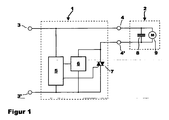
- FIG. 1 shows a schematic representation of an inventive, designed as a speed controller inventive device 1, which is connected via the terminals 3, 3 'to the public AC power.
- Upper terminals 4, 4 ', an electrical load 2 is connected to the device 1, which includes a parallel circuit of a motor 9 and a capacitor 8.
- the device 1 comprises a control device 5, a first switching device 6 and a second switching device designed as a triac 7.
- the first switching device 6 as a switching component includes a bipolar transistor, a field effect transistor or an IGBT.
- FIG. 2 shows simplified the course of the mains voltage 10 and the course of the current 11 by the electrical load 2.
- the first switching device 6 is driven, which slowly increases the current 11 through the electrical load 2.
- the capacitor 8 is charged to the current value of the mains voltage 10 and the current 11 drops to the value which from then on is essentially determined by the motor 9 becomes.
- the triac 7 is ignited and takes over the current 11, which has so far flowed through the first switching device 6. After the triac 7 is engaged, the first switching device 6 is turned off.
- the current 11 reaches the zero line through the electrical load 2 and the triac 7 also switches off. This completes one cycle.
- the invention relates to a method and a device 1, with a phase control, the current 11 with the aid of an active component initially controlled to increase until the RFI capacitor is charged in the load, and then switch to a triac 7 as a switching element, as these advantageous for inductive loads such as motors can be used.
Landscapes
- Engineering & Computer Science (AREA)
- Power Engineering (AREA)
- Control Of Ac Motors In General (AREA)
- Control Of Direct Current Motors (AREA)
Description
- Die Erfindung betrifft ein Verfahren und eine Vorrichtung zur Steuerung der effektiven Spannung an einem elektrischen Verbraucher, der elektrisch eine Parallelschaltung einer resitiv-induktiven Last und einer Kapazität darstellt.
- In der Praxis sind Maschinen, die mit einem Universalmotor an das Stromnetz angeschlossen werden, weit verbreitet. Dies können beispielsweise Hausgeräte , aber auch handgeführte, motorisch angetriebene Elektrowerkzeuge, wie z. B. Schlagbohrmaschinen, Winkelschleifer und Kreissägen sein. Häufig verfügen solche Maschinen über eine Drehzahlstelleinrichtung, mit der eine gewünschte Arbeitsgeschwindigkeit eingestellt werden kann. Dabei sind die Betätigungsmittel der Drehzahlstelleinrichtung üblicherweise an der Maschine angebracht und oft im Bereich des Handgriffs vorgesehen. Aus praktischen und/oder ergonomischen Erwägungen heraus kann es wünschenswert sein, die Drehzahl nicht an der Maschine selber zu verstellen, sondern die Drehzahlstelleinrichtung getrennt von der Maschine anzuordnen. Denn in der Praxis sind häufig Ständer oder Arbeitstische für die jeweiligen Maschinen verfügbar, in welcher die Maschinen einspannbar oder einsetzbar sind. In diesen Fällen ist es vorteilhaft, wenn die Maschine mit einem Fußpedal steuerbar ist.
- Solche Vorrichtungen, mit denen die Drehzahl eines am Stromnetz angeschlossenen Universalmotors beeinflussbar ist, sind weit verbreitet, billig und - wie vorerwähnt - häufig Bestandteil der Maschine. Entsprechende Vorrichtungen sind beispielsweise in den Druckschriften
DE 195 18 591 A1 undDE 196 52 190 A1 beschrieben, wobei die Drehzahl in diesen Dokumenten durch eine Widerstandsregelung (DE 195 18 591 A1 ) oder aber durch eine Phasenanschnittssteuerung (DE 196 52 190 A1 ) erfolgt. - Da der Motor, wie eingangs angegeben, dabei eine komplexe Last mit induktiver Komponente darstellt, kann er vorteilhaft mit einer einfachen Phasenanschnittsteuerung auf der Basis eines Triacs gesteuert werden. Triac und Motor sind in solchen Fällen dann in Reihe geschaltet. Jedoch wird durch die Schaltvorgänge des Triacs und durch das Bürstenfeuer eine Funkstörleistung erzeugt, die von der Maschine ins Stromnetz abgegeben wird. Um diese auf ein erträgliches Maß zu dämpfen, wird parallel zu der Reihenschaltung aus Motor und Triac ein Kondensator geschaltet.
- In der Praxis sind Elektrowerkzeuge oft derart, dass der Triac bei voller Drehzahl durch einen Schalter kurzgeschlossen wird, so dass eine Parallelschaltung aus Motor und Kondensator an den Netzanschlüssen anliegt.
- Es ist jedoch zu berücksichtigen, dass die Parallelschaltung aus Motor und Kondensator im Einschaltmoment eine komplexe Last mit kapazitivem Charakter darstellt, welche im Einschaltmoment einen Kurzschluss erzeugt, der u. a. den Triac und andere in Reihe geschaltete Komponenten stark belasten oder gar zerstören würde. Auch würden erhebliche Störungen im Netz durch den Kurzschluss verursacht werden.
- Eine bekannte Möglichkeit, den Stromanstieg im Einschaltmoment zu begrenzen, besteht darin, eine Spule in Reihe mit der Maschine zu schalten. Bei den üblicherweise verwendeten Entstörkondensatoren von 220 nF bis 470 nF müsste eine solche Spule eine Induktivität von einigen Millihenry aufweisen. Da sie dabei vom vollen Laststrom durchflossen wird, wäre sie groß, unhandlich und würde zudem auch hohe Kosten verursachen.
- Eine alternative Möglichkeit zur Schaltung von kapazitiven Lasten sind Phasenabschnittsteuerungen, die im Nulldurchgang der Netzspannung schalten und die Kapazität damit dem Netzspannungsverlauf folgend aufladen und insbesondere hohe Einschaltströme vermeiden. Da beim Abschalten der Maschine die Induktivität des Motors dominiert, führt dies dazu, dass der Strom durch den Motor zunächst aufrecht erhalten wird. Die Phasenabschnittsteuerung wird dann im Abschaltmoment hochohmig, und der Strom entlädt sich in den parallel geschalteten, zur Funkentstörung vorgesehenen Kondensator. Aufgrund der üblicherweise vorgesehenen Dimensionierung von Kondensator und Motor führt dies zu sehr hohen Spannungen, wodurch die Phasenabschnittsteuerung voraussichtlich zerstört würde.
- Um Phasenabschnittsteuerungen auch mit induktiven Lasten nutzen zu können, kann parallel zur Last ein geeignet dimensionierter Kondensator geschaltet werden, der den Strom aus dem Motor aufnehmen kann, ohne sich dabei auf eine für die Phasenabschnittsteuerung gefährliche Spannung aufzuladen. Die Dimensionierung des Kondensators ist dabei vom Motor und von seinen Betriebsbedingungen abhängig. Diese Dimensionierung erfordert zum einen entsprechendes Fachwissen bei der Auslegung, zum anderen sind besondere Maßnahmen für den Anschluss des Kondensators zu treffen. Außerdem sind derartige Kondensatoren relativ kostspielig.
- Aufgabe der Erfindung ist es, die vorgenannten Nachteile zu vermeiden und ein eingangs genanntes Verfahren und eine Vorrichtung anzugeben, mit dem bzw. der die Steuerung der effektiven Spannung an einem elektrischen Verbraucher, der elektrisch eine Parallelschaltung einer resitiv-induktiven Last und einer Kapazität darstellt, in zufrieden stellender Weise möglich ist.
- Diese Aufgabe wird durch das Verfahren in Anspruch 1 und die Vorrichtung in Anspruch 5 gelöst.
- Vorteilhafte Ausprägungen des erfindungsgemäßen Verfahrens und der erfindungsgemäßen Vorrichtung sind in den Unteransprüchen angegeben.
- Die erfindungsgemäße Phasenanschnittsteuerung zeichnet sich dadurch aus, dass zu Beginn einer Halbwelle das als Triac ausgebildete schaltende Bauteil geöffnet ist. Bei einem bestimmten Phasenwinkel, dem Anschnittwinkel, wird der Triac geschlossen und bleibt für den Rest der Halbwelle geschlossen.
- Wegen der Motorinduktivität ist der Strom im Nulldurchgang der Spannung noch nicht Null, sodass der Triac noch etwas länger geschlossen bleiben muss, bis der Nulldurchgang des Stromes erreicht ist. Dann wird er geöffnet und bleibt offen, bis die neue Phase den Anschnittwinkel erreicht hat. Der Triac wird beim Anschnittwinkel gezündet und bleibt solange niederohmig, bis der Strom durch den Triac den Haltestrom, der klein gegenüber dem Betriebsstrom durch den Motor ist, erreicht hat. Bei Unterschreitung des Haltestroms schaltet der Triac ab und bleibt bis zur nächsten Zündung ausgeschaltet. Damit der Triac zum Zündzeitpunkt nicht einen leeren Kondensator mit dem Kurzschlussstrom aufladen muss, wird der Kondensator vorher durch ein weiteres elektronisches Bauteil, dessen Spannungs-Strom-Kennlinie steuerbar ist, auf die gerade anliegende Netzspannung aufgeladen. Dieses Bauteil kann beispielsweise ein Bipolartransistor, ein Feldeffekttransistor oder ein IGBT sein. Es wird so angesteuert, dass der Strom am Ausgang nur langsam ansteigt und dabei den Funkentstörkondensator in der Maschine kontrolliert auflädt. Der Strom kann dabei auf einen Maximalwert begrenzt sein.
- Im Folgenden wird ein in der Zeichnung dargestelltes Ausführungsbeispiel der Erfindung erläutert. Es zeigen:
- Fig. 1
- eine schematische Darstellung eines Ausführungsbeispiels einer erfindungsgemäßen Vorrichtung, und
- Fig. 2
- eine vereinfachte Darstellung des Verlaufs der Netzspannung und des Stroms durch das Elektro- gerät der
Fig. 1 . - In allen Figuren werden für gleiche bzw. gleichartige Bauteile übereinstimmende Bezugszeichen verwendet.
-
Figur 1 zeigt in schematischer Darstellung eine erfindungsgemäße, als Drehzahlsteller ausgebildete erfindungsgemäße Vorrichtung 1, die über die Anschlussklemmen 3, 3' an das öffentliche Wechselstromnetz angeschlossen ist. Ober Anschlussklemmen 4, 4' ist ein elektrischer Verbraucher 2 an die Vorrichtung 1 angeschlossen, welcher eine Parallelschaltung aus einem Motor 9 und einem Kondensator 8 enthält. - Die Vorrichtung 1 umfasst eine Steuereinrichtung 5, eine erste Schaltvorrichtung 6 und eine als Triac 7 ausgebildete zweite Schaltvorrichtung. Dabei enthält die erste Schaltvorrichtung 6 als schaltendes Bauteil einen Bipolartransistor, einen Feldeffekttransistor oder einen IGBT.
-
Figur 2 zeigt vereinfacht den Verlauf der Netzspannung 10 und den Verlauf des Stromes 11 durch den elektrischen Verbraucher 2. Zum Zeitpunkt t1 wird die erste Schaltvorrichtung 6 angesteuert, die den Strom 11 durch den elektrischen Verbraucher 2 langsam steigert. Zum Zeitpunkt t2 ist der Kondensator 8 auf den aktuellen Wert der Netzspannung 10 aufgeladen und der Strom 11 sinkt auf den Wert, der von jetzt an im Wesentlichen durch den Motor 9 bestimmt wird. Zum Zeitpunkt t3 wird der Triac 7 gezündet und übernimmt den Strom 11, der bislang durch die erste Schaltvorrichtung 6 geflossen ist. Nachdem der Triac 7 eingerastet ist, wird die erste Schaltvorrichtung 6 abgeschaltet. Zum Zeitpunkt t4 erreicht der Strom 11 durch den elektrischen Verbraucher 2 die Nulllinie und der Triac 7 schaltet ebenfalls ab. Damit ist ein Zyklus beendet. - Zusammengefasst betrifft die Erfindung ein Verfahren und eine Vorrichtung 1, um mit einer Phasenanschnittsteuerung den Strom 11 mit Hilfe eines aktiven Bauelementes zunächst kontrolliert ansteigen zu lassen, bis der Funkentstörkondensator in der Last geladen ist, um dann auf einen Triac 7 als Schaltelement umzuschalten, da diese vorteilhaft bei induktiven Lasten wie Motoren eingesetzt werden können.
Claims (8)
- Verfahren zur Steuerung der effektiven Spannung an einem elektrischen Verbraucher (2), der elektrisch eine Parallelschaltung aus einem Motor (9) und einem Kondensator (8), insbesondere in Form eines Funkentstörkondensators, darstellt, dadurch gekennzeichnet, dass durch eine Steuereinrichtung (5) entsprechend einer Führungsgröße zum einen eine Schaltvorrichtung (6) so angesteuert wird, dass sie den Strom (11) durch den elektrischen Verbraucher (2) zum zumindest teilweisen Laden des Kondensators (8) kontrolliert ansteigen lässt, und durch die Steuereinrichtung (5) zum anderen ein Triac (7) zum Zwecke der Phasenanschnittsteuerung betrieben und beim Anschnittwinkel gezündet wird und dabei den Strom (11) durch den elektrischen Verbraucher (2) übernimmt, wobei die Steuereinrichtung (5) die Schaltvorrichtung (6) nach dem Einrasten des Triacs (7) abschaltet und wobei der Triac (7) erst dann gezündet wird, wenn der Kondensator (8) auf die anliegende Netzspannung (10) aufgeladen worden ist.
- Verfahren nach dem vorhergehenden Anspruch, dadurch gekennzeichnet, dass als Schaltvorrichtung (6) ein Bipolartransistor, insbesondere ein IGBT (Bipolartransistor mit isolierter Gate-Elektrode), oder ein Feldeffekttransistor verwendet wird.
- Verfahren nach einem der vorhergehenden Ansprüche, dadurch gekennzeichnet, dass die Führungsgröße fest oder veränderbar voreingestellt ist.
- Verfahren nach einem der vorhergehenden Ansprüche, dadurch gekennzeichnet, dass die Führungsgröße durch einen Benutzer zur Leistungs- und/oder Drehzahlbeeinflussung des elektrischen Verbrauchers (2) veränderbar ist.
- Vorrichtung (1) zur Steuerung der effektiven Spannung an einem elektrischen Verbraucher (2), der elektrisch eine Parallelschaltung aus einem Motor (9) und einem Kondensator (8), insbesondere in Form eines Funkentstörkondensators, darstellt, dadurch gekennzeichnet, dass die Vorrichtung eine Schaltvorrichtung (6), einen Triac (7) sowie eine Steuereinrichtung (5) zur Ansteuerung der Schaltvorrichtung (6) und zum Betreiben eines Triacs (7) zum Zwecke der Phasenanschnittsteuerung umfasst, wobei die Steuereinrichtung (5) entsprechend einer Führungsgröße zum einen die Schaltvorrichtung (6) so ansteuert, dass sie den Strom (11) durch den elektrischen Verbraucher (2) zum zumindest teilweisen Laden des Kondensators (8) kontrolliert ansteigen lässt, und durch die Steuereinrichtung (5) zum anderen den Triac (7) beim Anschnittwinkel zündet und dabei den Strom (11) durch den elektrischen Verbraucher (2) übernimmt, wobei die Steuereinrichtung (5) die Schaltvorrichtung (6) nach dem Einrasten des Triacs (7) abschaltet und wobei der Triac (7) erst dann gezündet wird, wenn der Kondensator (8) auf die anliegende Netzspannung (10) aufgeladen worden ist.
- Vorrichtung (1) nach dem vorhergehenden Anspruch, dadurch gekennzeichnet, dass die erste Schaltvorrichtung (6) als ein Bipolartransistor, insbesondere ein IGBT (Bipolartransistor mit isolierter Gate-Elektrode) oder ein Feldeffekttransistor ist.
- Vorrichtung (1) nach einem der vorhergehenden Ansprüche 5 oder 6, dadurch gekennzeichnet, dass die Führungsgröße fest oder veränderbar voreingestellt ist.
- Vorrichtung (1) nach einem der vorhergehenden Ansprüche 5, 6 oder 7, dadurch gekennzeichnet, dass die Führungsgröße durch einen Benutzer zur Leistungs- und/oder Drehzahlbeeinflussung des elektrischen Verbrauchers (2) veränderbar ist.
Priority Applications (2)
| Application Number | Priority Date | Filing Date | Title |
|---|---|---|---|
| AT09015593T ATE543248T1 (de) | 2009-12-17 | 2009-12-17 | Verfahren und vorrichtung zur steuerung der effektiven spannung an einem elektrischen verbraucher |
| EP09015593A EP2337215B1 (de) | 2009-12-17 | 2009-12-17 | Verfahren und Vorrichtung zur Steuerung der effektiven Spannung an einem elektrischen Verbraucher |
Applications Claiming Priority (1)
| Application Number | Priority Date | Filing Date | Title |
|---|---|---|---|
| EP09015593A EP2337215B1 (de) | 2009-12-17 | 2009-12-17 | Verfahren und Vorrichtung zur Steuerung der effektiven Spannung an einem elektrischen Verbraucher |
Publications (2)
| Publication Number | Publication Date |
|---|---|
| EP2337215A1 EP2337215A1 (de) | 2011-06-22 |
| EP2337215B1 true EP2337215B1 (de) | 2012-01-25 |
Family
ID=42136291
Family Applications (1)
| Application Number | Title | Priority Date | Filing Date |
|---|---|---|---|
| EP09015593A Not-in-force EP2337215B1 (de) | 2009-12-17 | 2009-12-17 | Verfahren und Vorrichtung zur Steuerung der effektiven Spannung an einem elektrischen Verbraucher |
Country Status (2)
| Country | Link |
|---|---|
| EP (1) | EP2337215B1 (de) |
| AT (1) | ATE543248T1 (de) |
Families Citing this family (1)
| Publication number | Priority date | Publication date | Assignee | Title |
|---|---|---|---|---|
| DE102017104652A1 (de) * | 2017-03-06 | 2018-09-06 | Festool Gmbh | Hand-Werkzeugmaschine |
Family Cites Families (2)
| Publication number | Priority date | Publication date | Assignee | Title |
|---|---|---|---|---|
| DE19518591A1 (de) * | 1995-05-20 | 1996-12-12 | Promed Gmbh | Kosmetisches Behandlungsgerät, insbesondere Nagelpflegegerät |
| DE19652190A1 (de) * | 1995-12-16 | 1997-07-03 | Promed Gmbh | Kosmetisches Behandlungsgerät, insbesondere Nagelpflegegerät |
-
2009
- 2009-12-17 AT AT09015593T patent/ATE543248T1/de active
- 2009-12-17 EP EP09015593A patent/EP2337215B1/de not_active Not-in-force
Also Published As
| Publication number | Publication date |
|---|---|
| EP2337215A1 (de) | 2011-06-22 |
| ATE543248T1 (de) | 2012-02-15 |
Similar Documents
| Publication | Publication Date | Title |
|---|---|---|
| DE60113983T2 (de) | Stromversorgung für ein hausgerät | |
| CH662907A5 (de) | Elektronische kupplung fuer elektrowerkzeuge mit waehlbarer drehzahl. | |
| EP0859452B1 (de) | Verfahren und Vorrichtung zur Leistungssteuerung von an ein Wechselspannungs-Versorgungsnetz angeschlossenen elektrischen Verbrauchern | |
| EP1568122B1 (de) | Vorrichtung und verfahren zum reduzieren der stromaufnahme während des anlaufens eines einphasen-wechselstrom-asynchron-motors | |
| EP2337215B1 (de) | Verfahren und Vorrichtung zur Steuerung der effektiven Spannung an einem elektrischen Verbraucher | |
| EP1923986B1 (de) | Wechselstromsteller für elektromagnetische schaltgeräte | |
| EP2223427B1 (de) | Verfahren und vorrichtung zum betreiben eines elektrischen antriebs mit hilfe einer phasenanschnittssteuerung | |
| DE102015111921A1 (de) | Schaltungsanordnung für eine Einschaltschutzeinrichtung | |
| EP2564500B1 (de) | Schalterfreie diac-ersatzschaltung | |
| DE2229694A1 (de) | Drehzahlregler fuer ein elektrowerkzeug | |
| DE102009039481A1 (de) | Vorrichtung und Verfahren zur Anlaufstrombegrenzung | |
| DE2703284A1 (de) | Sanftanlaufschaltung fuer elektromotore | |
| EP1992060B1 (de) | Vorrichtung und verfahren zur gleichspannungsversorgung von elektronischen ansteuerschaltungen für elektromotoren | |
| DE1936880A1 (de) | Schaltungsanordnung zur kontaktlosen Steuerung des Hilfsphasenstromes von Einphasenmotoren | |
| DE2929601A1 (de) | Anspeisungsvorrichtung fuer einen ozonerzeuger | |
| EP3174195B1 (de) | Verfahren und vorrichtung zum betreiben eines elektromotors | |
| EP0395589B1 (de) | Verfahren und Vorrichtung zum Begrenzen von Stromspitzen | |
| EP1217721B1 (de) | Kondensatornetzteil mit Starteinrichtung | |
| DE102010016326A1 (de) | Vorrichtung und Verfahren zur Anlaufstrombegrenzung | |
| EP3312993A1 (de) | Schaltungsanordnung zur ansteuerung einer zündbaren halbleiterschaltung | |
| EP3458638B1 (de) | Dynamische ansteuerung einer türöffnungsvorrichtung eines haushaltsgeräts, insbesondere mit dc-versorgungsspannung | |
| DE19718814A1 (de) | Verfahren und Vorrichtung zur Leistungsssteuerung von an ein Wechselspannungs-Versorgungsnetz angeschlossenen elektrischen Verbrauchern | |
| EP2727242B1 (de) | Haushaltsgerät mit einer netzschaltereinrichtung und verfahren zum versorgen eines elektrischen verbrauchers eines haushaltsgerätes über eine netzschaltereinrichtung | |
| WO2024160664A1 (de) | Induktionskochfeldvorrichtung | |
| EP1648083A2 (de) | Schaltungsanordnung zur Steuerung eines Elektromotors |
Legal Events
| Date | Code | Title | Description |
|---|---|---|---|
| PUAI | Public reference made under article 153(3) epc to a published international application that has entered the european phase |
Free format text: ORIGINAL CODE: 0009012 |
|
| 17P | Request for examination filed |
Effective date: 20101113 |
|
| AK | Designated contracting states |
Kind code of ref document: A1 Designated state(s): AT BE BG CH CY CZ DE DK EE ES FI FR GB GR HR HU IE IS IT LI LT LU LV MC MK MT NL NO PL PT RO SE SI SK SM TR |
|
| AX | Request for extension of the european patent |
Extension state: AL BA RS |
|
| RIC1 | Information provided on ipc code assigned before grant |
Ipc: H02P 25/14 20060101ALI20110616BHEP Ipc: H02P 7/295 20060101AFI20110616BHEP |
|
| GRAP | Despatch of communication of intention to grant a patent |
Free format text: ORIGINAL CODE: EPIDOSNIGR1 |
|
| GRAS | Grant fee paid |
Free format text: ORIGINAL CODE: EPIDOSNIGR3 |
|
| GRAA | (expected) grant |
Free format text: ORIGINAL CODE: 0009210 |
|
| AK | Designated contracting states |
Kind code of ref document: B1 Designated state(s): AT BE BG CH CY CZ DE DK EE ES FI FR GB GR HR HU IE IS IT LI LT LU LV MC MK MT NL NO PL PT RO SE SI SK SM TR |
|
| REG | Reference to a national code |
Ref country code: GB Ref legal event code: FG4D Free format text: NOT ENGLISH |
|
| REG | Reference to a national code |
Ref country code: CH Ref legal event code: EP |
|
| REG | Reference to a national code |
Ref country code: AT Ref legal event code: REF Ref document number: 543248 Country of ref document: AT Kind code of ref document: T Effective date: 20120215 |
|
| REG | Reference to a national code |
Ref country code: IE Ref legal event code: FG4D |
|
| REG | Reference to a national code |
Ref country code: DE Ref legal event code: R096 Ref document number: 502009002538 Country of ref document: DE Effective date: 20120322 |
|
| REG | Reference to a national code |
Ref country code: NL Ref legal event code: VDEP Effective date: 20120125 |
|
| LTIE | Lt: invalidation of european patent or patent extension |
Effective date: 20120125 |
|
| PG25 | Lapsed in a contracting state [announced via postgrant information from national office to epo] |
Ref country code: BG Free format text: LAPSE BECAUSE OF FAILURE TO SUBMIT A TRANSLATION OF THE DESCRIPTION OR TO PAY THE FEE WITHIN THE PRESCRIBED TIME-LIMIT Effective date: 20120425 Ref country code: NL Free format text: LAPSE BECAUSE OF FAILURE TO SUBMIT A TRANSLATION OF THE DESCRIPTION OR TO PAY THE FEE WITHIN THE PRESCRIBED TIME-LIMIT Effective date: 20120125 Ref country code: NO Free format text: LAPSE BECAUSE OF FAILURE TO SUBMIT A TRANSLATION OF THE DESCRIPTION OR TO PAY THE FEE WITHIN THE PRESCRIBED TIME-LIMIT Effective date: 20120425 Ref country code: LT Free format text: LAPSE BECAUSE OF FAILURE TO SUBMIT A TRANSLATION OF THE DESCRIPTION OR TO PAY THE FEE WITHIN THE PRESCRIBED TIME-LIMIT Effective date: 20120125 Ref country code: HR Free format text: LAPSE BECAUSE OF FAILURE TO SUBMIT A TRANSLATION OF THE DESCRIPTION OR TO PAY THE FEE WITHIN THE PRESCRIBED TIME-LIMIT Effective date: 20120125 Ref country code: IS Free format text: LAPSE BECAUSE OF FAILURE TO SUBMIT A TRANSLATION OF THE DESCRIPTION OR TO PAY THE FEE WITHIN THE PRESCRIBED TIME-LIMIT Effective date: 20120525 |
|
| REG | Reference to a national code |
Ref country code: IE Ref legal event code: FD4D |
|
| PG25 | Lapsed in a contracting state [announced via postgrant information from national office to epo] |
Ref country code: PL Free format text: LAPSE BECAUSE OF FAILURE TO SUBMIT A TRANSLATION OF THE DESCRIPTION OR TO PAY THE FEE WITHIN THE PRESCRIBED TIME-LIMIT Effective date: 20120125 Ref country code: GR Free format text: LAPSE BECAUSE OF FAILURE TO SUBMIT A TRANSLATION OF THE DESCRIPTION OR TO PAY THE FEE WITHIN THE PRESCRIBED TIME-LIMIT Effective date: 20120426 Ref country code: LV Free format text: LAPSE BECAUSE OF FAILURE TO SUBMIT A TRANSLATION OF THE DESCRIPTION OR TO PAY THE FEE WITHIN THE PRESCRIBED TIME-LIMIT Effective date: 20120125 Ref country code: PT Free format text: LAPSE BECAUSE OF FAILURE TO SUBMIT A TRANSLATION OF THE DESCRIPTION OR TO PAY THE FEE WITHIN THE PRESCRIBED TIME-LIMIT Effective date: 20120525 Ref country code: FI Free format text: LAPSE BECAUSE OF FAILURE TO SUBMIT A TRANSLATION OF THE DESCRIPTION OR TO PAY THE FEE WITHIN THE PRESCRIBED TIME-LIMIT Effective date: 20120125 |
|
| PG25 | Lapsed in a contracting state [announced via postgrant information from national office to epo] |
Ref country code: CY Free format text: LAPSE BECAUSE OF FAILURE TO SUBMIT A TRANSLATION OF THE DESCRIPTION OR TO PAY THE FEE WITHIN THE PRESCRIBED TIME-LIMIT Effective date: 20120125 |
|
| PG25 | Lapsed in a contracting state [announced via postgrant information from national office to epo] |
Ref country code: EE Free format text: LAPSE BECAUSE OF FAILURE TO SUBMIT A TRANSLATION OF THE DESCRIPTION OR TO PAY THE FEE WITHIN THE PRESCRIBED TIME-LIMIT Effective date: 20120125 Ref country code: SI Free format text: LAPSE BECAUSE OF FAILURE TO SUBMIT A TRANSLATION OF THE DESCRIPTION OR TO PAY THE FEE WITHIN THE PRESCRIBED TIME-LIMIT Effective date: 20120125 Ref country code: IE Free format text: LAPSE BECAUSE OF FAILURE TO SUBMIT A TRANSLATION OF THE DESCRIPTION OR TO PAY THE FEE WITHIN THE PRESCRIBED TIME-LIMIT Effective date: 20120125 Ref country code: DK Free format text: LAPSE BECAUSE OF FAILURE TO SUBMIT A TRANSLATION OF THE DESCRIPTION OR TO PAY THE FEE WITHIN THE PRESCRIBED TIME-LIMIT Effective date: 20120125 Ref country code: SE Free format text: LAPSE BECAUSE OF FAILURE TO SUBMIT A TRANSLATION OF THE DESCRIPTION OR TO PAY THE FEE WITHIN THE PRESCRIBED TIME-LIMIT Effective date: 20120125 Ref country code: RO Free format text: LAPSE BECAUSE OF FAILURE TO SUBMIT A TRANSLATION OF THE DESCRIPTION OR TO PAY THE FEE WITHIN THE PRESCRIBED TIME-LIMIT Effective date: 20120125 Ref country code: CZ Free format text: LAPSE BECAUSE OF FAILURE TO SUBMIT A TRANSLATION OF THE DESCRIPTION OR TO PAY THE FEE WITHIN THE PRESCRIBED TIME-LIMIT Effective date: 20120125 |
|
| PG25 | Lapsed in a contracting state [announced via postgrant information from national office to epo] |
Ref country code: IT Free format text: LAPSE BECAUSE OF FAILURE TO SUBMIT A TRANSLATION OF THE DESCRIPTION OR TO PAY THE FEE WITHIN THE PRESCRIBED TIME-LIMIT Effective date: 20120125 Ref country code: SK Free format text: LAPSE BECAUSE OF FAILURE TO SUBMIT A TRANSLATION OF THE DESCRIPTION OR TO PAY THE FEE WITHIN THE PRESCRIBED TIME-LIMIT Effective date: 20120125 |
|
| PLBE | No opposition filed within time limit |
Free format text: ORIGINAL CODE: 0009261 |
|
| STAA | Information on the status of an ep patent application or granted ep patent |
Free format text: STATUS: NO OPPOSITION FILED WITHIN TIME LIMIT |
|
| 26N | No opposition filed |
Effective date: 20121026 |
|
| REG | Reference to a national code |
Ref country code: DE Ref legal event code: R097 Ref document number: 502009002538 Country of ref document: DE Effective date: 20121026 |
|
| PG25 | Lapsed in a contracting state [announced via postgrant information from national office to epo] |
Ref country code: ES Free format text: LAPSE BECAUSE OF FAILURE TO SUBMIT A TRANSLATION OF THE DESCRIPTION OR TO PAY THE FEE WITHIN THE PRESCRIBED TIME-LIMIT Effective date: 20120506 |
|
| BERE | Be: lapsed |
Owner name: ERGOBIONIK G.M.B.H. Effective date: 20121231 |
|
| PG25 | Lapsed in a contracting state [announced via postgrant information from national office to epo] |
Ref country code: MC Free format text: LAPSE BECAUSE OF NON-PAYMENT OF DUE FEES Effective date: 20121231 |
|
| REG | Reference to a national code |
Ref country code: FR Ref legal event code: ST Effective date: 20130830 |
|
| PG25 | Lapsed in a contracting state [announced via postgrant information from national office to epo] |
Ref country code: BE Free format text: LAPSE BECAUSE OF NON-PAYMENT OF DUE FEES Effective date: 20121231 |
|
| PG25 | Lapsed in a contracting state [announced via postgrant information from national office to epo] |
Ref country code: FR Free format text: LAPSE BECAUSE OF NON-PAYMENT OF DUE FEES Effective date: 20130102 Ref country code: MT Free format text: LAPSE BECAUSE OF FAILURE TO SUBMIT A TRANSLATION OF THE DESCRIPTION OR TO PAY THE FEE WITHIN THE PRESCRIBED TIME-LIMIT Effective date: 20120125 |
|
| PG25 | Lapsed in a contracting state [announced via postgrant information from national office to epo] |
Ref country code: TR Free format text: LAPSE BECAUSE OF FAILURE TO SUBMIT A TRANSLATION OF THE DESCRIPTION OR TO PAY THE FEE WITHIN THE PRESCRIBED TIME-LIMIT Effective date: 20120125 |
|
| PG25 | Lapsed in a contracting state [announced via postgrant information from national office to epo] |
Ref country code: LU Free format text: LAPSE BECAUSE OF NON-PAYMENT OF DUE FEES Effective date: 20121217 Ref country code: SM Free format text: LAPSE BECAUSE OF FAILURE TO SUBMIT A TRANSLATION OF THE DESCRIPTION OR TO PAY THE FEE WITHIN THE PRESCRIBED TIME-LIMIT Effective date: 20120125 |
|
| PG25 | Lapsed in a contracting state [announced via postgrant information from national office to epo] |
Ref country code: HU Free format text: LAPSE BECAUSE OF FAILURE TO SUBMIT A TRANSLATION OF THE DESCRIPTION OR TO PAY THE FEE WITHIN THE PRESCRIBED TIME-LIMIT Effective date: 20091217 |
|
| REG | Reference to a national code |
Ref country code: CH Ref legal event code: PL |
|
| GBPC | Gb: european patent ceased through non-payment of renewal fee |
Effective date: 20131217 |
|
| PG25 | Lapsed in a contracting state [announced via postgrant information from national office to epo] |
Ref country code: CH Free format text: LAPSE BECAUSE OF NON-PAYMENT OF DUE FEES Effective date: 20131231 Ref country code: LI Free format text: LAPSE BECAUSE OF NON-PAYMENT OF DUE FEES Effective date: 20131231 |
|
| PG25 | Lapsed in a contracting state [announced via postgrant information from national office to epo] |
Ref country code: GB Free format text: LAPSE BECAUSE OF NON-PAYMENT OF DUE FEES Effective date: 20131217 |
|
| PG25 | Lapsed in a contracting state [announced via postgrant information from national office to epo] |
Ref country code: MK Free format text: LAPSE BECAUSE OF FAILURE TO SUBMIT A TRANSLATION OF THE DESCRIPTION OR TO PAY THE FEE WITHIN THE PRESCRIBED TIME-LIMIT Effective date: 20120125 |
|
| REG | Reference to a national code |
Ref country code: AT Ref legal event code: MM01 Ref document number: 543248 Country of ref document: AT Kind code of ref document: T Effective date: 20141217 |
|
| PG25 | Lapsed in a contracting state [announced via postgrant information from national office to epo] |
Ref country code: AT Free format text: LAPSE BECAUSE OF NON-PAYMENT OF DUE FEES Effective date: 20141217 |
|
| PGFP | Annual fee paid to national office [announced via postgrant information from national office to epo] |
Ref country code: DE Payment date: 20171220 Year of fee payment: 9 |
|
| REG | Reference to a national code |
Ref country code: DE Ref legal event code: R119 Ref document number: 502009002538 Country of ref document: DE |
|
| PG25 | Lapsed in a contracting state [announced via postgrant information from national office to epo] |
Ref country code: DE Free format text: LAPSE BECAUSE OF NON-PAYMENT OF DUE FEES Effective date: 20190702 |